EP4379916A1 - Copy cell - Google Patents
Copy cell Download PDFInfo
- Publication number
- EP4379916A1 EP4379916A1 EP23212902.3A EP23212902A EP4379916A1 EP 4379916 A1 EP4379916 A1 EP 4379916A1 EP 23212902 A EP23212902 A EP 23212902A EP 4379916 A1 EP4379916 A1 EP 4379916A1
- Authority
- EP
- European Patent Office
- Prior art keywords
- region
- copy cell
- thickness
- thermal conductivity
- copy
- Prior art date
- Legal status (The legal status is an assumption and is not a legal conclusion. Google has not performed a legal analysis and makes no representation as to the accuracy of the status listed.)
- Pending
Links
Images


Classifications
-
- G—PHYSICS
- G01—MEASURING; TESTING
- G01R—MEASURING ELECTRIC VARIABLES; MEASURING MAGNETIC VARIABLES
- G01R31/00—Arrangements for testing electric properties; Arrangements for locating electric faults; Arrangements for electrical testing characterised by what is being tested not provided for elsewhere
- G01R31/36—Arrangements for testing, measuring or monitoring the electrical condition of accumulators or electric batteries, e.g. capacity or state of charge [SoC]
- G01R31/3644—Constructional arrangements
- G01R31/3648—Constructional arrangements comprising digital calculation means, e.g. for performing an algorithm
-
- H—ELECTRICITY
- H01—ELECTRIC ELEMENTS
- H01M—PROCESSES OR MEANS, e.g. BATTERIES, FOR THE DIRECT CONVERSION OF CHEMICAL ENERGY INTO ELECTRICAL ENERGY
- H01M50/00—Constructional details or processes of manufacture of the non-active parts of electrochemical cells other than fuel cells, e.g. hybrid cells
- H01M50/10—Primary casings; Jackets or wrappings
- H01M50/102—Primary casings; Jackets or wrappings characterised by their shape or physical structure
- H01M50/107—Primary casings; Jackets or wrappings characterised by their shape or physical structure having curved cross-section, e.g. round or elliptic
-
- G—PHYSICS
- G01—MEASURING; TESTING
- G01M—TESTING STATIC OR DYNAMIC BALANCE OF MACHINES OR STRUCTURES; TESTING OF STRUCTURES OR APPARATUS, NOT OTHERWISE PROVIDED FOR
- G01M99/00—Subject matter not provided for in other groups of this subclass
- G01M99/002—Thermal testing
-
- G—PHYSICS
- G01—MEASURING; TESTING
- G01N—INVESTIGATING OR ANALYSING MATERIALS BY DETERMINING THEIR CHEMICAL OR PHYSICAL PROPERTIES
- G01N25/00—Investigating or analyzing materials by the use of thermal means
- G01N25/20—Investigating or analyzing materials by the use of thermal means by investigating the development of heat, i.e. calorimetry, e.g. by measuring specific heat, by measuring thermal conductivity
-
- G—PHYSICS
- G01—MEASURING; TESTING
- G01N—INVESTIGATING OR ANALYSING MATERIALS BY DETERMINING THEIR CHEMICAL OR PHYSICAL PROPERTIES
- G01N1/00—Sampling; Preparing specimens for investigation
- G01N1/28—Preparing specimens for investigation including physical details of (bio-)chemical methods covered elsewhere, e.g. G01N33/50, C12Q
-
- G—PHYSICS
- G01—MEASURING; TESTING
- G01N—INVESTIGATING OR ANALYSING MATERIALS BY DETERMINING THEIR CHEMICAL OR PHYSICAL PROPERTIES
- G01N25/00—Investigating or analyzing materials by the use of thermal means
- G01N25/18—Investigating or analyzing materials by the use of thermal means by investigating thermal conductivity
-
- G—PHYSICS
- G01—MEASURING; TESTING
- G01R—MEASURING ELECTRIC VARIABLES; MEASURING MAGNETIC VARIABLES
- G01R31/00—Arrangements for testing electric properties; Arrangements for locating electric faults; Arrangements for electrical testing characterised by what is being tested not provided for elsewhere
- G01R31/36—Arrangements for testing, measuring or monitoring the electrical condition of accumulators or electric batteries, e.g. capacity or state of charge [SoC]
- G01R31/396—Acquisition or processing of data for testing or for monitoring individual cells or groups of cells within a battery
-
- H—ELECTRICITY
- H01—ELECTRIC ELEMENTS
- H01M—PROCESSES OR MEANS, e.g. BATTERIES, FOR THE DIRECT CONVERSION OF CHEMICAL ENERGY INTO ELECTRICAL ENERGY
- H01M6/00—Primary cells; Manufacture thereof
- H01M6/02—Details
-
- H—ELECTRICITY
- H01—ELECTRIC ELEMENTS
- H01M—PROCESSES OR MEANS, e.g. BATTERIES, FOR THE DIRECT CONVERSION OF CHEMICAL ENERGY INTO ELECTRICAL ENERGY
- H01M6/00—Primary cells; Manufacture thereof
- H01M6/50—Methods or arrangements for servicing or maintenance, e.g. for maintaining operating temperature
- H01M6/5027—Dummy cells
-
- Y—GENERAL TAGGING OF NEW TECHNOLOGICAL DEVELOPMENTS; GENERAL TAGGING OF CROSS-SECTIONAL TECHNOLOGIES SPANNING OVER SEVERAL SECTIONS OF THE IPC; TECHNICAL SUBJECTS COVERED BY FORMER USPC CROSS-REFERENCE ART COLLECTIONS [XRACs] AND DIGESTS
- Y02—TECHNOLOGIES OR APPLICATIONS FOR MITIGATION OR ADAPTATION AGAINST CLIMATE CHANGE
- Y02E—REDUCTION OF GREENHOUSE GAS [GHG] EMISSIONS, RELATED TO ENERGY GENERATION, TRANSMISSION OR DISTRIBUTION
- Y02E60/00—Enabling technologies; Technologies with a potential or indirect contribution to GHG emissions mitigation
- Y02E60/10—Energy storage using batteries
Definitions
- the present disclosure relates to a copy cell for simulating thermal characteristics of a real battery cell.
- a thermal test of a real battery cell When a thermal test of a real battery cell is conducted, the test is conducted at a Crate in a low range. This is due to the danger of testing a real battery cell at a high temperature range.
- a thermal test may be performed using a copy cell instead of a real battery in the case that it is dangerous to test the real battery at high temperatures or if the real battery cell is unavailable due to being in the development stage. In this case, the test is generally conducted by copying only the shape with metal such as aluminum or plastic.
- a copy cell using only a single material has the same thermal characteristics, e.g., thermal conductivity, in all directions and thus may not completely simulate the thermal characteristics of an anisotropic battery cell.
- Embodiments are directed to copy cell including a first region made of a first material and having a cylindrical shape, a second region located outside the first region and made of a second material, and a third region located outside the second region and made of the first material. This arrangement allows higher flexibility when adjusting the thermal conductivity of the copy cell in order to mimic conventional (real) battery cells.
- the first material may be a metal, including stainless steel
- the second material may be an insulating material, including plastic or urethane.
- the second material may be in the form of a foam or a gel.
- the first region may have a first thickness that may be a distance from a center of the copy cell to an outer surface of the first region
- the second region may have a second thickness that may be a distance from the outer surface of the first region to an outer surface of the second region
- the ratio of the first thickness to the second thickness may be about 3:1.
- the first thickness of the first region is about 8 mm to 14 mm.
- the first thickness of the first region is about 9 to 11 mm, most preferred 10 mm.
- the third region has a third thickness that is a distance from the outer surface of the second region to the outer surface of the third region, and the ratio of the first thickness to the third thickness may be about 0.9: 1 to about 2:1, preferably about 1:1, most preferred (1.03:1).
- the copy cell has a diameter and a height wherein a diameter-to-height ratio is about 1:1.7 to about 1:1.8.
- the first region may have a thermal conductivity of about 13 W/mK to about 18 W/mK.
- the second region may have a thermal conductivity of about 0.3 W/mK.
- a thermal conductivity in the thickness direction of the copy cell may be about 0.6 W/mK to about 2.4 W/mK.
- a thermal conductivity in the thickness direction of the copy cell may be about 1.3 W/mK. This thermal conductivity is particularly suitable to mimic thermal conductivity of a conventional battery cell.
- the diameter of the copy cell 100 may be 46 mm.
- a copy cell 100 may include a first region 110 located at the center, a second region 120 located outside the first region 110, and a third region 130 located outside the second region 120.
- the copy cell 100 may be formed in a cylindrical shape.
- the first region 110 may be located in the most central region of the copy cell 100 and may be formed in a substantially cylindrical shape.
- the first region 110 may be made of a first material.
- the first material may be a metal, and may include, e.g., stainless steel (SUS, steel use stainless).
- the thermal conductivity of the first material may be about 13 W/mK to 18 W/mK.
- the first region 110 may have a first thickness D1 that is a distance from the center of the copy cell 100 to the outer surface of the first region 110.
- the first thickness D1 may be the radius of the first region 110.
- the second region 120 may be formed outside the first region 110.
- the second region 120 may surround the outer surface of the first region 110 and may have a ring shape in cross section.
- the second region 120 may be made of a second material different from the first material forming the first region 110.
- the second material may be an insulating material such as, e.g., plastic or urethane.
- Said insulating material may for instance be a polymer, preferably a polyurethane.
- the second material may be in the form of a foam or a gel.
- the second material may be in the form of a polymer foam or a polymer gel, preferably a polyurethane foam or a polyurethane gel.
- the thermal conductivity of the second material may be about 0.3 W/mK.
- the thermal conductivity of the second material may be about 0.29 W/mK to about 0.31 W/mK.
- the second region 120 may have a second thickness D2 that may be a distance from the outer surface of the first region 110 to the outer surface of the second region 120.
- the third region 130 may be formed outside the second region 120.
- the third region 130 may surround the outer surface of the second region 120 and may have a ring shape in cross section.
- the third region 130 may be made of the first material, that is, the same material as the first region 110.
- the third region 130 may have a third thickness D3 that may be a distance from the outer surface of the second region 120 to the outer surface of the third region 130, i.e., the outer surface of the copy cell 100.
- the second region 120 may be made of the second material and may be formed between the first region 110 and the third region 130.
- the third region 130 may have a thermal conductivity of about 13 W/mK to about 18 W/mK, since the first region 110 and the third region are made of the first material.
- the first region 110 and the third region may be made of the first material, that is, the same material, thereby adjusting the thermal characteristics, e.g., thermal conductivity, in the thickness direction of the copy cell 100.
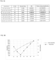
- FIG. 3A is a table showing the thermal conductivity in the thickness direction of a copy cell according to the ratio of the first thickness D1 of the first region 110 to the second thickness D2 of the second region 120.
- FIG. 3B is a graph showing the table of FIG. 3A .
- FIGS. 3A and 3B The table and graph shown in FIGS. 3A and 3B will be described with reference to the copy cell 100 shown in FIGS. 1 and 2 .
- the thickness of the first region 110 and the second region 120 are changed and thermal conductivity of the copy cell 100 measured.
- the diameter of the copy cell 100 is 46 mm
- the first thickness D1 of the first region 110 is about 8 to 14 mm.
- the experimental method for measuring the thermal conductivity of the copy cell 100 may be guided by Korean standards, such as ISO 8301, ISO 8302, ASTM C117, ASTM C518, and KS L 9016.
- the thermal conductivity measurement method of the copy cell 100 may adopt a plate-direct method (or a guarded hot plate apparatus method) used in ISO 8302, ASTM C177, or KS L 9016.
- a temperature difference between both sides of a measuring material may be set to be 10 °C or more, and the thermal conductivity may be determined by measuring the temperature of both sides of an object tested upon reaching a steady state with power supplied to a main hot plate.
- the experimental method for measuring the thermal conductivity of the copy cell 100 may adopt a plate-comparison method, or a heat flow meter apparatus method, used in ISO 8301, ASTM C518, or KS L 9016.
- a temperature difference between both sides of a measuring material may be set to be 10 °C or more.
- a test object is considered to be in a steady state if a test object reaches a state in which the temperature difference between sides does not change by more than 1% per 30 minutes, the output of a heat flow meter does not change by more than 2% per 30 minutes, and the temperatures of both surfaces of the test object do not change in the same direction.
- Thermal conductivity may be obtained by measuring the values after reaching the steady state.
- copy cells #1 to #7 with diameter of 46 mm were prepared as follows:
- the copy cell having a thermal conductivity the most similar to the thermal conductivity of the real battery cell was the third copy cell (#3) having the ratio 3:1 between the first thickness D1 of the first region 110 to the second thickness D2 of the second region 120.
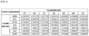
- FIG. 4 is a table showing the thermal conductivity in the thickness direction of a copy cell according to the thermal conductivity (CondA) of the first region 110 and the thermal conductivity (CondB) of the second region 120.
- the thermal conductivity in the thickness direction of the copy cell 100 was measured while changing the thermal conductivities of the first region 110 and the second region 120 and keeping the thickness ratio of the first region 110 and the second region 120 the same at 3:1 (D1:D2).
- the thermal conductivity (CondB) of the second region 120 determines the thermal conductivity in the thickness direction of the copy cell 100.
- the thermal conductivity of the second region 120 is 0.3 W/mK
- the thermal conductivity of the first region 110 can be varied between 15 W/mK and 21 W/mK and the thermal conductivity in the thickness direction of the copy cell 100 will stay around 1.3 W/mK.
- the thermal conductivity in the thickness direction of the copy cell will deviate from around 1.3 W/mk.
- 1.3 W/mK is the thermal conductivity in the thickness direction most similar to that of the real battery cell.
- thermal conductivity in the thickness direction of the copy cell can be controlled.
- the copy cell 100 may have a shape similar in appearance to a real battery cell.
- a thermal test of the battery cell if using the real battery cell, there are risks such as, at a high temperature range, ignition of the battery cell. Therefore, in the present disclosure, an alternative to the risk of using a real battery cell in a thermal test is presented in the form of a copy cell 100 having thermal characteristics similar to the real battery cell
- the thermal conductivity in the height direction (or vertical direction) of the copy cell can be adjusted so as to be similar to that of a real battery cell, but the thermal conductivity in the thickness direction (or horizontal direction) of the copy cell cannot be adjusted so as to be similar to a real battery cell.
- the thermal conductivity in the thickness direction of the copy cell does not match that of the real battery cell, the copy cell cannot simulate the thermal behavior of the real battery cell.
- the thermal conductivity in the thickness direction of the copy cell 100 may be adjusted similar to that of the real battery cell.
- first, second, etc. may be used herein to describe various members, elements, regions, layers and/or sections, these members, elements, regions, layers and/or sections should not be limited by these terms. These terms are only used to distinguish one member, element, region, layer and/or section from another. Thus, for example, a first member, a first element, a first region, a first layer and/or a first section discussed below could be termed a second member, a second element, a second region, a second layer and/or a second section without departing from the teachings of the present disclosure.
- spatially relative terms such as “beneath,” “below,” “lower,” “above,” “upper,” and the like, may be used herein for ease of description to describe one element or feature's relationship to another element(s) or feature(s) as illustrated in the figures. It will be understood that the spatially relative terms are intended to encompass different orientations of the device in use or operation in addition to the orientation depicted in the figures. For example, if the element or feature in the figures is turned over, elements described as “below” or “beneath” other elements or features would then be oriented “on” or “above” the other elements or features. Thus, the exemplary term “below” can encompass both an orientation of above and below.
Landscapes
- Physics & Mathematics (AREA)
- General Physics & Mathematics (AREA)
- Chemical & Material Sciences (AREA)
- Immunology (AREA)
- Analytical Chemistry (AREA)
- Biochemistry (AREA)
- General Health & Medical Sciences (AREA)
- Life Sciences & Earth Sciences (AREA)
- Health & Medical Sciences (AREA)
- Pathology (AREA)
- Chemical Kinetics & Catalysis (AREA)
- Electrochemistry (AREA)
- General Chemical & Material Sciences (AREA)
- Engineering & Computer Science (AREA)
- Manufacturing & Machinery (AREA)
- Battery Mounting, Suspending (AREA)
- Secondary Cells (AREA)
Abstract
A copy cell having a first region made of a first material, a second region outside the first region and made of a second material, and a third region outside the second region and made of the first material, for simulating thermal characteristics of a real battery cell.
Description
- The present disclosure relates to a copy cell for simulating thermal characteristics of a real battery cell.
- When a thermal test of a real battery cell is conducted, the test is conducted at a Crate in a low range. This is due to the danger of testing a real battery cell at a high temperature range. A thermal test may be performed using a copy cell instead of a real battery in the case that it is dangerous to test the real battery at high temperatures or if the real battery cell is unavailable due to being in the development stage. In this case, the test is generally conducted by copying only the shape with metal such as aluminum or plastic. However, a copy cell using only a single material has the same thermal characteristics, e.g., thermal conductivity, in all directions and thus may not completely simulate the thermal characteristics of an anisotropic battery cell.
- Embodiments are directed to copy cell including a first region made of a first material and having a cylindrical shape, a second region located outside the first region and made of a second material, and a third region located outside the second region and made of the first material. This arrangement allows higher flexibility when adjusting the thermal conductivity of the copy cell in order to mimic conventional (real) battery cells.
- In embodiments, the first material may be a metal, including stainless steel, and the second material may be an insulating material, including plastic or urethane. In embodiments, the second material may be in the form of a foam or a gel.
- In embodiments of the copy cell, the first region may have a first thickness that may be a distance from a center of the copy cell to an outer surface of the first region, the second region may have a second thickness that may be a distance from the outer surface of the first region to an outer surface of the second region, and the ratio of the first thickness to the second thickness may be about 3:1.
- In embodiments of the copy cell, the first thickness of the first region is about 8 mm to 14 mm. Preferably the first thickness of the first region is about 9 to 11 mm, most preferred 10 mm.
- In embodiments of the copy cell, the third region has a third thickness that is a distance from the outer surface of the second region to the outer surface of the third region, and the ratio of the first thickness to the third thickness may be about 0.9: 1 to about 2:1, preferably about 1:1, most preferred (1.03:1).
- In embodiments of the copy cell, the copy cell has a diameter and a height wherein a diameter-to-height ratio is about 1:1.7 to about 1:1.8.
- In embodiments of the copy cell, the first region may have a thermal conductivity of about 13 W/mK to about 18 W/mK.
- In embodiments of the copy cell, the second region may have a thermal conductivity of about 0.3 W/mK.
- In embodiments of the copy cell, a thermal conductivity in the thickness direction of the copy cell may be about 0.6 W/mK to about 2.4 W/mK.
- In embodiments of the copy cell, a thermal conductivity in the thickness direction of the copy cell may be about 1.3 W/mK. This thermal conductivity is particularly suitable to mimic thermal conductivity of a conventional battery cell.
- In embodiments of the copy cell, the diameter of the
copy cell 100 may be 46 mm. - Features will become apparent to those of skill in the art by describing in detail exemplary embodiments with reference to the attached drawings in which:
-
FIG. 1 a perspective view showing a copy cell according to an embodiment of the present disclosure; -
FIG. 2 is a perspective, cross-sectional view of the copy cell shown inFIG. 1 ; -
FIG. 3A is a table showing the thermal conductivity of a copy cell in the thickness direction according to the ratio of a first thickness of a first region to a second thickness of a second region; -
FIG. 3B is a graph of the table ofFIG. 3A ; and -
FIG. 4 is a table showing the thermal conductivity of a copy cell in the thickness direction according to the thermal conductivity of the first region and the thermal conductivity of the second region. - Example embodiments will now be described more fully hereinafter with reference to the accompanying drawings; however, they may be embodied in different forms and should not be construed as limited to the embodiments set forth herein. Rather, these embodiments are provided so that this disclosure will be thorough and complete, and will fully convey exemplary implementations to those skilled in the art. Like reference numerals refer to like elements throughout.
- Referring to
FIGS. 1 and2 , acopy cell 100 according to an embodiment of the present disclosure may include afirst region 110 located at the center, asecond region 120 located outside thefirst region 110, and athird region 130 located outside thesecond region 120. - The
copy cell 100 may be formed in a cylindrical shape. The ratio of the diameter D to the height H of thecopy cell 100 may be about 1:1.7 to about 1:1.8. In some embodiments, the ratio of the diameter D to the height H of thecopy cell 100 may be 1:1.739 (D:H = 1:1.739). That is, the height H of the copy cell may be relatively greater than the diameter D of thecopy cell 100. - The
first region 110 may be located in the most central region of thecopy cell 100 and may be formed in a substantially cylindrical shape. Thefirst region 110 may be made of a first material. The first material may be a metal, and may include, e.g., stainless steel (SUS, steel use stainless). The thermal conductivity of the first material may be about 13 W/mK to 18 W/mK. Thefirst region 110 may have a first thickness D1 that is a distance from the center of thecopy cell 100 to the outer surface of thefirst region 110. Here, the first thickness D1 may be the radius of thefirst region 110. - The
second region 120 may be formed outside thefirst region 110. Thesecond region 120 may surround the outer surface of thefirst region 110 and may have a ring shape in cross section. Thesecond region 120 may be made of a second material different from the first material forming thefirst region 110. The second material may be an insulating material such as, e.g., plastic or urethane. Said insulating material may for instance be a polymer, preferably a polyurethane. In some embodiments the second material may be in the form of a foam or a gel. For instance, the second material may be in the form of a polymer foam or a polymer gel, preferably a polyurethane foam or a polyurethane gel. The thermal conductivity of the second material may be about 0.3 W/mK. Preferably, the thermal conductivity of the second material may be about 0.29 W/mK to about 0.31 W/mK. Thesecond region 120 may have a second thickness D2 that may be a distance from the outer surface of thefirst region 110 to the outer surface of thesecond region 120. The ratio of the second thickness D2 of thesecond region 120 to the first thickness D1 of thefirst region 110 may be 1:3 (D2:D1 = 1:3). - The
third region 130 may be formed outside thesecond region 120. Thethird region 130 may surround the outer surface of thesecond region 120 and may have a ring shape in cross section. Thethird region 130 may be made of the first material, that is, the same material as thefirst region 110. Thethird region 130 may have a third thickness D3 that may be a distance from the outer surface of thesecond region 120 to the outer surface of thethird region 130, i.e., the outer surface of thecopy cell 100. - As described above, in the
copy cell 100 according to the present disclosure, thesecond region 120 may be made of the second material and may be formed between thefirst region 110 and thethird region 130. Thethird region 130 may have a thermal conductivity of about 13 W/mK to about 18 W/mK, since thefirst region 110 and the third region are made of the first material. Thefirst region 110 and the third region may be made of the first material, that is, the same material, thereby adjusting the thermal characteristics, e.g., thermal conductivity, in the thickness direction of thecopy cell 100. -
FIG. 3A is a table showing the thermal conductivity in the thickness direction of a copy cell according to the ratio of the first thickness D1 of thefirst region 110 to the second thickness D2 of thesecond region 120.FIG. 3B is a graph showing the table ofFIG. 3A . - The table and graph shown in
FIGS. 3A and 3B will be described with reference to thecopy cell 100 shown inFIGS. 1 and2 . - In the present disclosure, in order to fabricate a
copy cell 100 similar to a real battery cell, i.e., having thermal conductivity of 1.3 W/mK in the thickness direction, the thickness of thefirst region 110 and thesecond region 120 are changed and thermal conductivity of thecopy cell 100 measured. Here, the diameter of thecopy cell 100 is 46 mm, and the first thickness D1 of thefirst region 110 is about 8 to 14 mm. - The experimental method for measuring the thermal conductivity of the
copy cell 100 may be guided by Korean standards, such as ISO 8301, ISO 8302, ASTM C117, ASTM C518, and KS L 9016. For example, the thermal conductivity measurement method of thecopy cell 100 may adopt a plate-direct method (or a guarded hot plate apparatus method) used in ISO 8302, ASTM C177, or KS L 9016. In the plate-direct method, a temperature difference between both sides of a measuring material may be set to be 10 °C or more, and the thermal conductivity may be determined by measuring the temperature of both sides of an object tested upon reaching a steady state with power supplied to a main hot plate. In addition, for example, the experimental method for measuring the thermal conductivity of thecopy cell 100 may adopt a plate-comparison method, or a heat flow meter apparatus method, used in ISO 8301, ASTM C518, or KS L 9016. In the plate-comparison method, a temperature difference between both sides of a measuring material may be set to be 10 °C or more. A test object is considered to be in a steady state if a test object reaches a state in which the temperature difference between sides does not change by more than 1% per 30 minutes, the output of a heat flow meter does not change by more than 2% per 30 minutes, and the temperatures of both surfaces of the test object do not change in the same direction. Thermal conductivity may be obtained by measuring the values after reaching the steady state. - Referring to
FIGS. 3A and 3B ,copy cells # 1 to #7 with diameter of 46 mm were prepared as follows: - (1) a first copy cell (#1) having a ratio of the first thickness D1 of the
first region 110 to the second thickness D2 of thesecond region 120 of 1:1 and with a first thickness D1 of 8 mm, - (2) a second copy cell (#2) having a ratio of the first thickness D1 of the
first region 110 to the second thickness D2 of thesecond region 120 of 2:1 and with a first thickness D1 of 9 mm, - (3) a third copy cell (#3) having a ratio of the first thickness D1 of the
first region 110 to the second thickness D2 of thesecond region 120 of 3:1 and with a first thickness D1 of 10 mm, - (4) a fourth copy cell (#4) having a ratio of the first thickness D1 of the
first region 110 to the second thickness D2 of thesecond region 120 of 4:1 and with a first thickness D1 of 11 mm, - (5) a fifth copy cell (#5) having a ratio of the first thickness D1 of the
first region 110 to the second thickness D2 of thesecond region 120 of 5:1 and with a first thickness D1 of 12 mm, - (6) a sixth copy cell (#6) having a ratio of the first thickness D1 of the
first region 110 to the second thickness D2 of thesecond region 120 of 6:1 and with a first thickness D1 of 13 mm, and - (7) seventh copy cell (#7) having a ratio of the first thickness D1 of the
first region 110 to the second thickness D2 of thesecond region 120 of 7:1 and with a first thickness D1 of 14 mm. - In addition, as shown in
FIG. 3A , when the total conductivity of each respectivecopy cells # 1 to #7 was measured, the thermal conductivity were as follows: - (#1) was about 0.617 W/mK,
- (#2) was about 0.995 W/mK,
- (#3) was about 1.328 W/mK,
- (#4) was about 1.626 W/mK,
- (#5) was about 1.896 W/mK,
- (#6) was about 2.141 W/mK, and
- (#7) was about 2.365 W/mK.
- That is, the copy cell having a thermal conductivity the most similar to the thermal conductivity of the real battery cell was the third copy cell (#3) having the ratio 3:1 between the first thickness D1 of the
first region 110 to the second thickness D2 of thesecond region 120. - In addition, referring to
FIG. 3B , by expressing the difference between the measured conductivity of each copy cell (#1-#7) and the thermal conductivity of the real battery cell as a percentage (Percent Error), it can be seen that the difference in thermal conductivity between the real battery cells and the third copy cell (#3) had the least Percent Error and therefore was closest in value at 3.8%. -
FIG. 4 is a table showing the thermal conductivity in the thickness direction of a copy cell according to the thermal conductivity (CondA) of thefirst region 110 and the thermal conductivity (CondB) of thesecond region 120. Here, the thermal conductivity in the thickness direction of thecopy cell 100 was measured while changing the thermal conductivities of thefirst region 110 and thesecond region 120 and keeping the thickness ratio of thefirst region 110 and thesecond region 120 the same at 3:1 (D1:D2). - Referring to
FIG. 4 , it can be seen that the thermal conductivity (CondB) of thesecond region 120, rather than the thermal conductivity (CondA) of thefirst region 110, determines the thermal conductivity in the thickness direction of thecopy cell 100. In some embodiments, as shown inFIG. 4 , if the thermal conductivity of thesecond region 120 is 0.3 W/mK, the thermal conductivity of thefirst region 110 can be varied between 15 W/mK and 21 W/mK and the thermal conductivity in the thickness direction of thecopy cell 100 will stay around 1.3 W/mK. On the other hand, as shown inFIG. 4 , if the thermal conductivity of the second region is varied by even 0.05 w/mK, the thermal conductivity in the thickness direction of the copy cell will deviate from around 1.3 W/mk. Notably, 1.3 W/mK is the thermal conductivity in the thickness direction most similar to that of the real battery cell. - As described above, in the copy cell for the test of a battery cell test according to an embodiment of the present disclosure, by forming a second region made of a second material between a first region and a third region made of the same material, that is, the first material, thermal conductivity in the thickness direction of the copy cell can be controlled.
- By way of summation and review, the
copy cell 100 according to an embodimentt of the present disclosure may have a shape similar in appearance to a real battery cell. During a thermal test of the battery cell, if using the real battery cell, there are risks such as, at a high temperature range, ignition of the battery cell. Therefore, in the present disclosure, an alternative to the risk of using a real battery cell in a thermal test is presented in the form of acopy cell 100 having thermal characteristics similar to the real battery cell - In general, if a copy cell is manufactured with a single material, the thermal conductivity in the height direction (or vertical direction) of the copy cell can be adjusted so as to be similar to that of a real battery cell, but the thermal conductivity in the thickness direction (or horizontal direction) of the copy cell cannot be adjusted so as to be similar to a real battery cell. Specifically, as the size of a cylindrical battery cell is increased, side cooling is required. However, if the thermal conductivity in the thickness direction of the copy cell does not match that of the real battery cell, the copy cell cannot simulate the thermal behavior of the real battery cell. Therefore, in the present disclosure, by forming the
second region 120 made of the second material between thefirst region 110 and thethird region 130 made of the same material, that is, the first material, the thermal conductivity in the thickness direction of thecopy cell 100 may be adjusted similar to that of the real battery cell. - Examples of the present disclosure are provided to more completely explain the present disclosure to those skilled in the art, and the following examples may be modified in various other forms. The present disclosure, however, may be embodied in many different forms and should not be construed as being limited to the example (or exemplary) embodiments set forth herein. Rather, these example embodiments are provided so that this disclosure will be thorough and complete and will convey the aspects and features of the present disclosure to those skilled in the art.
- In addition, in the accompanying drawings, sizes or thicknesses of various components are exaggerated for brevity and clarity. Like numbers refer to like elements throughout. As used herein, the term "and/or" includes any and all combinations of one or more of the associated listed items. In addition, it will be understood that when an element A is referred to as being "connected to" an element B, the element A can be directly connected to the element B or an intervening element C may be present therebetween such that the element A and the element B are indirectly connected to each other.
- The terminology used herein is for the purpose of describing particular embodiments only and is not intended to be limiting of the disclosure. As used herein, the singular forms are intended to include the plural forms as well, unless the context clearly indicates otherwise. It will be further understood that the terms that the terms "comprise" and/or "comprising," when used in this specification, specify the presence of stated features, numbers, steps, operations, elements, and/or components, but do not preclude the presence or addition of one or more other features, numbers, steps, operations, elements, components, and/or groups thereof.
- It will be understood that, although the terms first, second, etc. may be used herein to describe various members, elements, regions, layers and/or sections, these members, elements, regions, layers and/or sections should not be limited by these terms. These terms are only used to distinguish one member, element, region, layer and/or section from another. Thus, for example, a first member, a first element, a first region, a first layer and/or a first section discussed below could be termed a second member, a second element, a second region, a second layer and/or a second section without departing from the teachings of the present disclosure.
- Spatially relative terms, such as "beneath," "below," "lower," "above," "upper," and the like, may be used herein for ease of description to describe one element or feature's relationship to another element(s) or feature(s) as illustrated in the figures. It will be understood that the spatially relative terms are intended to encompass different orientations of the device in use or operation in addition to the orientation depicted in the figures. For example, if the element or feature in the figures is turned over, elements described as "below" or "beneath" other elements or features would then be oriented "on" or "above" the other elements or features. Thus, the exemplary term "below" can encompass both an orientation of above and below.
- Here, the same reference numerals are attached to parts having similar configurations and operations throughout the specification. In addition, when a part is said to be electrically coupled to another part, this includes not only a case where it is directly connected but also a case where it is connected with another element interposed therebetween.
- Example embodiments have been disclosed herein, and although specific terms are employed, they are used and are to be interpreted in a generic and descriptive sense only and not for purpose of limitation. In some instances, as would be apparent to one of ordinary skill in the art as of the filing of the present application, features, characteristics, and/or elements described in connection with a particular embodiment may be used singly or in combination with features, characteristics, and/or elements described in connection with other embodiments unless otherwise specifically indicated. Accordingly, it will be understood by those of skill in the art that various changes in form and details may be made without departing from the scope of the present invention as set forth in the following claims.
| D1:D2 | D1 (mm) | D2 (mm) | D3 (mm) | D1: | |
| # | |||||
| 1 | 1:1 | 8 | 8.0 | 7.0 | 1.1:1 |
| #2 | 2:1 | 9 | 4.5 | 9.5 | 0.9:1 |
| #3 | 3:1 | 10 | 3.3 | 9.7 | 1:1 |
| #4 | 4:1 | 11 | 2.8 | 9.3 | 1.2:1 |
| #5 | 5:1 | 12 | 2.4 | 8.6 | 1.4:1 |
| #6 | 6:1 | 13 | 2.2 | 7.8 | 1.7:1 |
| #7 | 7:1 | 14 | 2.0 | 7.0 | 2:1 |
Claims (15)
- A copy cell (100), comprising:a first region (110) made of a first material and having a cylindrical shape;a second region (120) located outside the first region (110) and made of a second material; anda third region (130) located outside the second region (120) and made of the first material.
- The copy cell according to claim 1, wherein the first material is a metal.
- The copy cell according to claim 2, wherein the first material is stainless steel.
- The copy cell according to one of the preceding claims, wherein the second material is an insulating material.
- The copy cell according to claim 4, wherein the second material is plastic or urethane.
- The copy cell according to claims 4 or 5, wherein the second material is in the form of a foam or a gel.
- The copy cell according to one of the preceding claims, wherein:the first region (110) has a first thickness (D1) that is a distance from a center of the cell to an outer surface of the first region (110);the second region (120) has a second thickness (D2) that is a distance from the outer surface of the first region (110) to an outer surface of the second region (120); andthe ratio of the first thickness (D1) to the second thickness (D2) is about 3:1.
- The copy cell according to claim 7, wherein first thickness D1 of the first region 110 is about 8 mm to 14 mm.
- The copy cell according to claim 7 or 8, wherein third region (130) has a third thickness (D3) that is a distance from the outer surface of the second region (120) to the outer surface of the third region (130); and
the ratio of the first thickness (D1) to the third thickness (D3) is about 1:1. - The copy cell according to one of the preceding claims, wherein the copy cell has a height (H) and a diameter (D), and a diameter-to-height ratio (D:H) of the copy cell is about 1:1.7 to about 1:1.8.
- The copy cell according to one of the preceding claims , wherein the first region (110) has a thermal conductivity of about 13 W/mK to about 18 W/mK.
- The copy cell according to one of the preceding claims, wherein the second region (120) has a thermal conductivity of about 0.3 W/mK.
- The copy cell according to claim 9, wherein the third region (130) has a thermal conductivity of about 13 W/mK to about 18 W/mK.
- The copy cell according to one of the preceding claims, wherein a thermal conductivity in a thickness direction of the copy cell is about 0.6 W/mK to about 2.4 W/mK.
- The copy cell according to claim 14, wherein a thermal conductivity in a thickness direction of the copy cell is about 1.3 W/mK.
Applications Claiming Priority (1)
| Application Number | Priority Date | Filing Date | Title |
|---|---|---|---|
| KR1020220164288A KR20240080707A (en) | 2022-11-30 | 2022-11-30 | Copy cell for test of real battery cell |
Publications (1)
| Publication Number | Publication Date |
|---|---|
| EP4379916A1 true EP4379916A1 (en) | 2024-06-05 |
Family
ID=89030043
Family Applications (1)
| Application Number | Title | Priority Date | Filing Date |
|---|---|---|---|
| EP23212902.3A Pending EP4379916A1 (en) | 2022-11-30 | 2023-11-29 | Copy cell |
Country Status (4)
| Country | Link |
|---|---|
| US (1) | US20240175925A1 (en) |
| EP (1) | EP4379916A1 (en) |
| KR (1) | KR20240080707A (en) |
| CN (1) | CN118112038A (en) |
Citations (3)
| Publication number | Priority date | Publication date | Assignee | Title |
|---|---|---|---|---|
| FR3034261A1 (en) * | 2015-03-23 | 2016-09-30 | Ifp Energies Now | MODULAR ELECTRICAL BATTERY COMPRISING A THERMAL CONTROL DEVICE |
| EP3525273A1 (en) * | 2018-02-07 | 2019-08-14 | Commissariat à l'Energie Atomique et aux Energies Alternatives | Dummy electric battery for simulating and characterising thermal management solutions |
| EP3809488A1 (en) * | 2019-10-16 | 2021-04-21 | Commissariat à l'Energie Atomique et aux Energies Alternatives | Dummy battery |
-
2022
- 2022-11-30 KR KR1020220164288A patent/KR20240080707A/en active Pending
-
2023
- 2023-10-02 US US18/375,688 patent/US20240175925A1/en active Pending
- 2023-11-29 CN CN202311615060.XA patent/CN118112038A/en active Pending
- 2023-11-29 EP EP23212902.3A patent/EP4379916A1/en active Pending
Patent Citations (3)
| Publication number | Priority date | Publication date | Assignee | Title |
|---|---|---|---|---|
| FR3034261A1 (en) * | 2015-03-23 | 2016-09-30 | Ifp Energies Now | MODULAR ELECTRICAL BATTERY COMPRISING A THERMAL CONTROL DEVICE |
| EP3525273A1 (en) * | 2018-02-07 | 2019-08-14 | Commissariat à l'Energie Atomique et aux Energies Alternatives | Dummy electric battery for simulating and characterising thermal management solutions |
| EP3809488A1 (en) * | 2019-10-16 | 2021-04-21 | Commissariat à l'Energie Atomique et aux Energies Alternatives | Dummy battery |
Also Published As
| Publication number | Publication date |
|---|---|
| KR20240080707A (en) | 2024-06-07 |
| CN118112038A (en) | 2024-05-31 |
| US20240175925A1 (en) | 2024-05-30 |
Similar Documents
| Publication | Publication Date | Title |
|---|---|---|
| EP4379916A1 (en) | Copy cell | |
| KR101656598B1 (en) | Gasket and production method for same, and spark plug and production method for same | |
| JP2011007256A (en) | Clamp using titanium alloy with low-temperature workability | |
| US8945748B2 (en) | Battery pack | |
| EP0185661A1 (en) | HEAT-INSULATED STRUCTURES FOR LOW-TEMPERATURE PIPES OR CRYOGENIC PIPES. | |
| KR101182687B1 (en) | Bellows lining method | |
| JP5383140B2 (en) | Method for producing multilayer elastic belt for electrophotographic apparatus | |
| KR102072824B1 (en) | Flexible pipe and exhaust heating system with the same | |
| CN105522326B (en) | Coefficient of thermal expansion adjustment for composite laminates using fiber steering | |
| US8378264B2 (en) | Heater for piping | |
| CN110194680A (en) | A kind of high-strength prestressed composite ceramics and preparation method thereof | |
| US20040175571A1 (en) | Filled PTFE membranes and gaskets made therefrom | |
| US8260183B2 (en) | Soft pressure roller composition for fusing system | |
| KR102052362B1 (en) | Flexible pipe and exhaust heating system with the same | |
| CN106808172A (en) | A kind of preparation method of titanium alloy component hot forming tool | |
| US20130168439A1 (en) | Thermal Processing Method for Welding Area on Branched Pipes | |
| US20250003065A1 (en) | Method and apparatus for gas and vapor deposition precursor delivery heater | |
| EP2434330A1 (en) | Method of manufacturing eyeglass lens | |
| KR101904775B1 (en) | Method of determination proper pressure of heat flow meter | |
| KR20230077035A (en) | Liquid hydrogen storage tank to which 3D printing-epoxy composite material is applied and its manufacturing method | |
| CN114181483A (en) | Tetrapropylene-fluoride rubber composition and preparation method and application thereof | |
| US10012558B2 (en) | Combustion pressure sensor | |
| US20240201711A1 (en) | Controlling flow of a fluid using thermally deformable channel | |
| EP2900745B1 (en) | A composition, connector, process for improving bonding between two or more means for conveying fluids and system for conveying fluids | |
| KR20180122669A (en) | A heat generating fixing belt, a method of manufacturing a heat generating fixing belt, and an image fixing apparatus (HEAT FIXING BELT, METHOD FOR PRODUCING HEAT FIXING BELT, AND IMAGE FIXATION DEVICE) |
Legal Events
| Date | Code | Title | Description |
|---|---|---|---|
| PUAI | Public reference made under article 153(3) epc to a published international application that has entered the european phase |
Free format text: ORIGINAL CODE: 0009012 |
|
| STAA | Information on the status of an ep patent application or granted ep patent |
Free format text: STATUS: REQUEST FOR EXAMINATION WAS MADE |
|
| 17P | Request for examination filed |
Effective date: 20231129 |
|
| AK | Designated contracting states |
Kind code of ref document: A1 Designated state(s): AL AT BE BG CH CY CZ DE DK EE ES FI FR GB GR HR HU IE IS IT LI LT LU LV MC ME MK MT NL NO PL PT RO RS SE SI SK SM TR |