EP4379912A1 - Secondary battery - Google Patents
Secondary battery Download PDFInfo
- Publication number
- EP4379912A1 EP4379912A1 EP24171316.3A EP24171316A EP4379912A1 EP 4379912 A1 EP4379912 A1 EP 4379912A1 EP 24171316 A EP24171316 A EP 24171316A EP 4379912 A1 EP4379912 A1 EP 4379912A1
- Authority
- EP
- European Patent Office
- Prior art keywords
- protrusion
- current collecting
- gap
- region
- electrode assembly
- Prior art date
- Legal status (The legal status is an assumption and is not a legal conclusion. Google has not performed a legal analysis and makes no representation as to the accuracy of the status listed.)
- Granted
Links
Images




Classifications
-
- H—ELECTRICITY
- H01—ELECTRIC ELEMENTS
- H01M—PROCESSES OR MEANS, e.g. BATTERIES, FOR THE DIRECT CONVERSION OF CHEMICAL ENERGY INTO ELECTRICAL ENERGY
- H01M50/00—Constructional details or processes of manufacture of the non-active parts of electrochemical cells other than fuel cells, e.g. hybrid cells
- H01M50/50—Current conducting connections for cells or batteries
- H01M50/531—Electrode connections inside a battery casing
- H01M50/533—Electrode connections inside a battery casing characterised by the shape of the leads or tabs
-
- H—ELECTRICITY
- H01—ELECTRIC ELEMENTS
- H01M—PROCESSES OR MEANS, e.g. BATTERIES, FOR THE DIRECT CONVERSION OF CHEMICAL ENERGY INTO ELECTRICAL ENERGY
- H01M50/00—Constructional details or processes of manufacture of the non-active parts of electrochemical cells other than fuel cells, e.g. hybrid cells
- H01M50/50—Current conducting connections for cells or batteries
- H01M50/528—Fixed electrical connections, i.e. not intended for disconnection
-
- H—ELECTRICITY
- H01—ELECTRIC ELEMENTS
- H01M—PROCESSES OR MEANS, e.g. BATTERIES, FOR THE DIRECT CONVERSION OF CHEMICAL ENERGY INTO ELECTRICAL ENERGY
- H01M10/00—Secondary cells; Manufacture thereof
- H01M10/04—Construction or manufacture in general
- H01M10/0431—Cells with wound or folded electrodes
-
- H—ELECTRICITY
- H01—ELECTRIC ELEMENTS
- H01M—PROCESSES OR MEANS, e.g. BATTERIES, FOR THE DIRECT CONVERSION OF CHEMICAL ENERGY INTO ELECTRICAL ENERGY
- H01M10/00—Secondary cells; Manufacture thereof
- H01M10/04—Construction or manufacture in general
- H01M10/0472—Vertically superposed cells with vertically disposed plates
-
- H—ELECTRICITY
- H01—ELECTRIC ELEMENTS
- H01M—PROCESSES OR MEANS, e.g. BATTERIES, FOR THE DIRECT CONVERSION OF CHEMICAL ENERGY INTO ELECTRICAL ENERGY
- H01M50/00—Constructional details or processes of manufacture of the non-active parts of electrochemical cells other than fuel cells, e.g. hybrid cells
- H01M50/10—Primary casings; Jackets or wrappings
- H01M50/102—Primary casings; Jackets or wrappings characterised by their shape or physical structure
- H01M50/103—Primary casings; Jackets or wrappings characterised by their shape or physical structure prismatic or rectangular
-
- H—ELECTRICITY
- H01—ELECTRIC ELEMENTS
- H01M—PROCESSES OR MEANS, e.g. BATTERIES, FOR THE DIRECT CONVERSION OF CHEMICAL ENERGY INTO ELECTRICAL ENERGY
- H01M50/00—Constructional details or processes of manufacture of the non-active parts of electrochemical cells other than fuel cells, e.g. hybrid cells
- H01M50/10—Primary casings; Jackets or wrappings
- H01M50/147—Lids or covers
-
- H—ELECTRICITY
- H01—ELECTRIC ELEMENTS
- H01M—PROCESSES OR MEANS, e.g. BATTERIES, FOR THE DIRECT CONVERSION OF CHEMICAL ENERGY INTO ELECTRICAL ENERGY
- H01M50/00—Constructional details or processes of manufacture of the non-active parts of electrochemical cells other than fuel cells, e.g. hybrid cells
- H01M50/50—Current conducting connections for cells or batteries
- H01M50/543—Terminals
- H01M50/552—Terminals characterised by their shape
- H01M50/553—Terminals adapted for prismatic, pouch or rectangular cells
-
- H—ELECTRICITY
- H01—ELECTRIC ELEMENTS
- H01M—PROCESSES OR MEANS, e.g. BATTERIES, FOR THE DIRECT CONVERSION OF CHEMICAL ENERGY INTO ELECTRICAL ENERGY
- H01M50/00—Constructional details or processes of manufacture of the non-active parts of electrochemical cells other than fuel cells, e.g. hybrid cells
- H01M50/50—Current conducting connections for cells or batteries
- H01M50/572—Means for preventing undesired use or discharge
- H01M50/584—Means for preventing undesired use or discharge for preventing incorrect connections inside or outside the batteries
- H01M50/586—Means for preventing undesired use or discharge for preventing incorrect connections inside or outside the batteries inside the batteries, e.g. incorrect connections of electrodes
-
- H—ELECTRICITY
- H01—ELECTRIC ELEMENTS
- H01M—PROCESSES OR MEANS, e.g. BATTERIES, FOR THE DIRECT CONVERSION OF CHEMICAL ENERGY INTO ELECTRICAL ENERGY
- H01M50/00—Constructional details or processes of manufacture of the non-active parts of electrochemical cells other than fuel cells, e.g. hybrid cells
- H01M50/50—Current conducting connections for cells or batteries
- H01M50/572—Means for preventing undesired use or discharge
- H01M50/584—Means for preventing undesired use or discharge for preventing incorrect connections inside or outside the batteries
- H01M50/59—Means for preventing undesired use or discharge for preventing incorrect connections inside or outside the batteries characterised by the protection means
- H01M50/593—Spacers; Insulating plates
-
- H—ELECTRICITY
- H01—ELECTRIC ELEMENTS
- H01M—PROCESSES OR MEANS, e.g. BATTERIES, FOR THE DIRECT CONVERSION OF CHEMICAL ENERGY INTO ELECTRICAL ENERGY
- H01M50/00—Constructional details or processes of manufacture of the non-active parts of electrochemical cells other than fuel cells, e.g. hybrid cells
- H01M50/50—Current conducting connections for cells or batteries
- H01M50/531—Electrode connections inside a battery casing
- H01M50/538—Connection of several leads or tabs of wound or folded electrode stacks
-
- Y—GENERAL TAGGING OF NEW TECHNOLOGICAL DEVELOPMENTS; GENERAL TAGGING OF CROSS-SECTIONAL TECHNOLOGIES SPANNING OVER SEVERAL SECTIONS OF THE IPC; TECHNICAL SUBJECTS COVERED BY FORMER USPC CROSS-REFERENCE ART COLLECTIONS [XRACs] AND DIGESTS
- Y02—TECHNOLOGIES OR APPLICATIONS FOR MITIGATION OR ADAPTATION AGAINST CLIMATE CHANGE
- Y02E—REDUCTION OF GREENHOUSE GAS [GHG] EMISSIONS, RELATED TO ENERGY GENERATION, TRANSMISSION OR DISTRIBUTION
- Y02E60/00—Enabling technologies; Technologies with a potential or indirect contribution to GHG emissions mitigation
- Y02E60/10—Energy storage using batteries
-
- Y—GENERAL TAGGING OF NEW TECHNOLOGICAL DEVELOPMENTS; GENERAL TAGGING OF CROSS-SECTIONAL TECHNOLOGIES SPANNING OVER SEVERAL SECTIONS OF THE IPC; TECHNICAL SUBJECTS COVERED BY FORMER USPC CROSS-REFERENCE ART COLLECTIONS [XRACs] AND DIGESTS
- Y02—TECHNOLOGIES OR APPLICATIONS FOR MITIGATION OR ADAPTATION AGAINST CLIMATE CHANGE
- Y02P—CLIMATE CHANGE MITIGATION TECHNOLOGIES IN THE PRODUCTION OR PROCESSING OF GOODS
- Y02P70/00—Climate change mitigation technologies in the production process for final industrial or consumer products
- Y02P70/50—Manufacturing or production processes characterised by the final manufactured product
Definitions
- This application relates to the field of batteries, and in particular, to a secondary battery.
- a secondary battery generally includes an electrode assembly, a housing, electrode terminals, and a current collecting member.
- the current collecting member is configured to electrically connect the electrode assembly and the electrode terminals.
- tabs are disposed on the electrode assembly, and the tabs are connected to the current collecting member.
- the tabs are relatively long. To reduce space occupied by the tabs, the tabs are generally bent. However, for lack of support at a root of the tabs, the tabs are very likely to be inserted into the electrode assembly during the bending, thereby causing short-circuit risks.
- an objective of this application is to provide a secondary battery, and the secondary battery can reduce short-circuit risks and improve safety performance.
- the secondary battery includes an electrode assembly, a housing, a top cover assembly, a current collecting member, and an insulation member.
- the electrode assembly is accommodated in the housing and includes a body portion and a first tab.
- the first tab extends from one end of the body portion in a transverse direction.
- the top cover assembly includes a top cover plate and a first electrode terminal disposed on the top cover plate.
- the top cover plate is connected to the housing, and the first electrode terminal is connected to the current collecting member.
- the insulation member is disposed between the body portion and the current collecting member.
- the insulation member includes a through gap. The first tab passes through the gap and is connected to the current collecting member.
- the insulation member includes a substrate and a protrusion.
- the protrusion extends from a surface of the substrate, the surface being away from the body portion in the transverse direction.
- the gap extends from a surface of the protrusion and runs through the protrusion and the substrate, the surface being away from the substrate.
- the current collecting member includes a first current collecting plate.
- the first current collecting plate is located on a side of the substrate and fits snugly with the body portion, the side being away from the body portion.
- the protrusion is located at a lateral position of the first current collecting plate in a longitudinal direction. The first current collecting plate is connected to the first tab.
- a thickness of the protrusion is less than or equal to a thickness of the first current collecting plate.
- the protrusion of the insulation member is plural in number.
- the plurality of protrusions include a first protrusion and a second protrusion arranged in the longitudinal direction.
- the first current collecting plate is located between the first protrusion and the second protrusion.
- the gap is plural in number.
- the plurality of gaps include a first gap and a second gap. The first gap runs through the first protrusion and the substrate, and the second gap runs through the second protrusion and the substrate.
- the electrode assembly is plural in number.
- the plurality of electrode assemblies include a first electrode assembly and a second electrode assembly. The first tab of the first electrode assembly passes through the first gap and is connected to the first current collecting plate.
- the first tab of the second electrode assembly passes through the second gap and is connected to the first current collecting plate.
- the first gap and the second gap are staggered.
- the first tab passing through the first gap is bent toward a side close to the second electrode assembly and is connected to the first current collecting plate.
- the first tab passing through the second gap is bent toward a side close to the first electrode assembly and is connected to the first current collecting plate.
- each protrusion includes a first region and a second region.
- the first region and the second region are arranged along a height direction. In the longitudinal direction, a width of the first region is greater than a width of the second region.
- the first gap runs through the first region of the first protrusion, and the second gap runs through the first region of the second protrusion.
- an arrangement direction of the first region and the second region of the first protrusion is opposite to an arrangement direction of the first region and the second region of the second protrusion.
- an edge that is of the first region and close to the first current collecting plate is flush with an edge that is of the second region and close to the first current collecting plate.
- a via hole is disposed in the body portion.
- the via hole is formed on at least one side of the first protrusion, the side being away from the first current collecting plate.
- the plurality of protrusions include a third protrusion and a fourth protrusion.
- the first protrusion, the second protrusion, the third protrusion, and the fourth protrusion are arranged sequentially along the longitudinal direction.
- the current collecting member further includes a second current collecting plate.
- the second current collecting plate is located between the third protrusion and the fourth protrusion.
- the plurality of gaps further include a third gap and a fourth gap.
- the third gap runs through the third protrusion and the substrate.
- the fourth gap runs through the fourth protrusion and the substrate.
- the plurality of electrode assemblies include a third electrode assembly and a fourth electrode assembly.
- the first tab of the third electrode assembly passes through the third gap and is connected to the second current collecting plate.
- the first tab of the fourth electrode assembly passes through the fourth gap and is connected to the second current collecting plate.
- the insulation member is bonded to the current collecting member.
- the gap of the insulation member can tuck the tabs and restrain the tabs from deforming in a process of bending the tabs, thereby reducing risks of inserting a root region of the tabs into the body portion, avoiding a short circuit, and improving safety performance.
- connection may be a fixed connection, or a detachable connection, or an integrated connection, or an electrical connection or signal connection; or may be a direct connection or an indirect connection implemented through an intermediate medium.
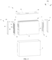
- a secondary battery includes an electrode assembly 1, a housing 2, a top cover assembly 3, a current collecting member 4, and an insulation member 5.
- the electrode assembly 1 includes a first electrode plate 14, a second electrode plate 15, and a separator 16.
- the separator 16 is disposed between the first electrode plate 14 and the second electrode plate 15.
- the electrode assembly 1 is formed by spirally winding the first electrode plate 14, the separator 16, and the second electrode plate 15, and forms a flat structure by being pressed under a pressure.
- the electrode assembly 1 is a core part for the secondary battery to implement functions of charging and discharging.
- the first electrode plate 14 includes a first current collector and a first active material layer coated on a surface of the first current collector.
- the first electrode plate 14 may be a positive electrode plate.
- the first current collector is an aluminum foil.
- the first active material layer includes active materials such as lithium manganate and lithium iron phosphate.
- the active materials (such as lithium manganate and lithium iron phosphate), a binder, a conductive agent, and a solvent may be made into a slurry, and then the slurry may be coated on both surfaces of the first current collector. After the slurry is cured, the first active material layer is formed.
- the first current collector is coated with the first active material layer.
- the first active material layer and a region that is of the first current collector and coated with the first active material layer form a first coated region 141 of the first electrode plate 14.
- a region that is of the first current collector and not coated with the first active material layer forms a first uncoated region 142 of the first electrode plate 14.
- the first uncoated regions 142 may be plural in number and are spaced out. After the first electrode plate 14 is wound into shape, the plurality of first uncoated regions 142 are stacked together.
- the second electrode plate 15 includes a second current collector and a second active material layer coated on a surface of the second current collector.
- the second active material layer and a region that is of the second current collector and coated with the second active material layer form a second coated region of the second electrode plate 15.
- the region that is of the second current collector and not coated with the second active material layer forms a second uncoated region of the second electrode plate 15.
- the second uncoated regions may be plural in number and are spaced out. After the second electrode plate 15 is wound into shape, the plurality of second uncoated regions are stacked together.
- the second electrode plate 15 is similar to the first electrode plate 14 in structure, but differs in that the second current collector may be made of a copper foil material and the second active material layer includes an active material such as graphite or silicon.
- the separator 16 may be a polyethylene (PE) film, a polypropylene (PP) film, or a PP-PE-PP three-layered composite film.
- PE polyethylene
- PP polypropylene
- the electrode assembly 1 After the electrode assembly 1 is wound into shape, from a perspective of an appearance of the electrode assembly 1, the electrode assembly 1 includes a body portion 11, a first tab 12, and a second tab 13.
- the body portion 11 includes the first coated region 141, the separator 16, and the second coated region of the second electrode plate 15.
- the first tab 12 includes a plurality of first uncoated regions 142 stacked together.
- the second tab 13 includes a plurality of second uncoated regions stacked together.
- a spool of the electrode assembly 1 is substantially parallel to a transverse direction X.
- the first tab 12 extends from one end of the body portion 11 in the transverse direction X.
- the second tab 13 extends from the other end of the body portion 11 in the transverse direction X.
- the housing 2 may be in a hexahedral shape or another shape.
- the housing 2 forms an accommodation cavity interiorly to accommodate the electrode assembly 1 and an electrolytic solution.
- the housing 2 forms an opening at one end, and the electrode assembly 1 can be placed into the accommodation cavity of the housing 2 through the opening.
- the housing 2 may be made of a conductive metal material.
- the housing 2 is made of aluminum or an aluminum alloy.
- the top cover assembly 3 includes a top cover plate 31, a first electrode terminal 32, and a second electrode terminal 33.
- the top cover plate 31 is disposed on the housing 2 and covers the opening of the housing 2 to enclose the electrode assembly 1 in the housing 2.
- the top cover plate 31 may be connected to the housing 2 by welding or by other means.
- the first electrode terminal 32 and the second electrode terminal 33 are disposed on the top cover plate 31.
- the first electrode terminal 32 is electrically connected to the first tab 12, and the second electrode terminal 33 is electrically connected to the second tab 13.
- One current collecting member 4 is connected to the first tab 12 and the first electrode terminal 32.
- the other current collecting member 4 is connected to the second tab 13 and the second electrode terminal 33.
- the first tab 12 includes a plurality of layers of first uncoated regions 142.
- the plurality of layers of first uncoated regions 142 are welded onto the current collecting member 4. After completion of the welding, to reduce space occupied by the first tab 12, the first tab 12 is generally bent. However, for the part located between a weld region and the body portion 11 in the first uncoated region 142, the plurality of layers of first uncoated regions 142 are in a dispersed state. In a process of bending the first tab 12, the plurality of layers of first uncoated regions 142 in the dispersed state lack support. Therefore, a root of each first uncoated region 142 is very likely to be deformed and inserted inwardly into the body portion 11, thereby causing a short-circuit risk.
- an insulation member 5 is disposed on one side of the body portion 11 according to this application.
- the insulation member 5 is disposed between the body portion 11 and the current collecting member 4, and the insulation member 5 includes a through gap S.
- the gap S may be slit-shaped.
- the first tab 12 passes through the gap S and is connected to the current collecting member 4.
- the part at which the first tab 12 passes through the gap S may be welded to the current collecting member 4.
- the gap S can tuck the plurality of layers of first uncoated regions 142 of the first tab 12 together.
- the gap S of the insulation member 5 can tuck the first tab 12 and restrain the first tab 12 from deforming in a process of bending the first tab 12, thereby reducing risks of inserting the root of the first tab 12 into the body portion 11, avoiding a short circuit, and improving safety performance.
- the insulation member 5 may be fixed to the current collecting member 4 to prevent the insulation member 5 from shaking in the secondary battery.
- the insulation member 5 may be bonded to the current collecting member 4.
- the insulation member 5 includes a substrate 51 and a protrusion 52.
- the protrusion 52 extends from a surface of the substrate 51, the surface being away from the body portion 11 in the transverse direction X.
- the substrate 51 is approximately a flat plate perpendicular to the transverse direction X.
- the gap S extends from a surface of the protrusion 52 and runs through the protrusion 52 and the substrate 51, the surface being away from the substrate 51.
- the protrusion 52 disposed can increase a depth of the gap S in the transverse direction X, so as to increase the ability of the gap S to tuck the first tab 12.
- the current collecting member 4 includes a first current collecting plate 41 and a terminal connecting plate 43.
- the first current collecting plate 41 extends in a direction approximately perpendicular to the transverse direction X.
- the first current collecting plate 41 is located on a side of the substrate 51, the side being away from the body portion 11.
- the terminal connecting plate 43 is bent against the first current collecting plate 41, and connects the first current collecting plate 41 and the first electrode terminal 32.
- the terminal connecting plate 43 may be located above the substrate 51 in a height direction Z.
- the first current collecting plate 41 fits snugly with the body portion 11.
- the first current collecting plate 41 is bonded to the body portion 11.
- the protrusion 52 is located at a lateral position of the first current collecting plate 41 in a longitudinal direction Y. This avoids superimposing the protrusion 52 on the first current collecting plate 41 in the transverse direction X, reduces the space occupied by the insulation member 5 and the current collecting member 4 in the transverse direction X, and increases the energy density.
- the first current collecting plate 41 is connected to the first tab 12. After passing through the gap S, the first tab 12 may be connected to the first current collecting plate 41 by ultrasonic welding.
- a thickness of the protrusion 52 is less than or equal to a thickness of the first current collecting plate 41. This prevents the protrusion 52 from occupying additional space in the transverse direction X.
- the protrusion 52 of the insulation member 5 is plural in number, and the plurality of protrusions 52 include a first protrusion 52a and a second protrusion 52b arranged in the longitudinal direction Y.
- the first current collecting plate 41 is located between the first protrusion 52a and the second protrusion 52b.
- the first protrusion 52a and the second protrusion 52b can support the first current collecting plate 41 from both sides, restrain the first current collecting plate 41 from shaking, and reduce risks of rupturing the first tab 12.
- the first protrusion 52a and the second protrusion 52b also help to position and assemble the first current collecting plate 41.
- a plurality of electrode assemblies 1 are generally disposed. If the first tabs 12 of the plurality of electrode assemblies 1 pass through an identical gap S, the plurality of first tabs 12 may be rather staggered, thereby making it more difficult to tuck the first tabs 12.
- a plurality of gaps S are disposed.
- the plurality of gaps S include a first gap S1 and a second gap S2.
- the first gap S1 runs through the first protrusion 52a and the substrate 51.
- the second gap S2 runs through the second protrusion 52b and the substrate 51.
- the plurality of electrode assemblies 1 include a first electrode assembly 1a and a second electrode assembly 1b.
- the first tab 12 of the first electrode assembly 1a passes through the first gap S1 and is connected to the first current collecting plate 41.
- the first tab 12 of the second electrode assembly 1b passes through the second gap S2 and is connected to the first current collecting plate 41.
- the first gap S1 and the second gap S2 are staggered. In other words, in the height direction Z, the first gap S1 and the second gap S2 are at different heights.
- the first tab 12 passing through the first gap S1 is bent toward a side close to the second electrode assembly 1b and is connected to the first current collecting plate 41.
- the first tab 12 passing through the second gap S2 is bent toward a side close to the first electrode assembly 1a and is connected to the first current collecting plate 41.
- the first tab 12 of the first electrode assembly 1a is flush with the first tab 12 of the second electrode assembly 1b in the height direction Z, the first tab 12 of the first electrode assembly 1a and the first tab 12 of the second electrode assembly 1b are likely to be stacked together. This increases the difficulty of welding and causes risks of poor welding.
- the first gap S1 and the second gap S2 are staggered longitudinally. Therefore, the first tab 12 of the first electrode assembly 1a and the first tab 12 of the second electrode assembly 1b can be staggered longitudinally to avoid stacking the first tab 12 of the first electrode assembly 1a and the first tab 12 of the second electrode assembly 1b together and reduce risks of poor welding.
- each protrusion 52 includes a first region 521 and a second region 522.
- the first region 521 and the second region 522 are arranged along the height direction Z. In the longitudinal direction Y, a width of the first region 521 is greater than a width of the second region 522.
- the first gap S1 runs through the first region 521 of the first protrusion 52a.
- the second gap S2 runs through the first region 521 of the second protrusion 52b.
- the width of the first region 521 is increased so that it is convenient to open the gap S in the first region 521.
- the width of the second region 522 may be reduced appropriately to reduce the space occupied by the second region 522 and increase the energy density.
- an arrangement direction of the first region 521 and the second region 522 of the first protrusion 52a is opposite to an arrangement direction of the first region 521 and the second region 522 of the second protrusion 52b. This causes the first gap S1 and the second gap S2 to be staggered longitudinally.
- an edge that is of the first region 521 and close to the first current collecting plate 41 is flush with an edge that is of the second region 522 and close to the first current collecting plate 41.
- the flush arranged edges of the first region 521 and the second region 522 can more effectively support the first current collecting plate 41 and retrain the first current collecting plate 41 from shaking in the longitudinal direction Y.
- a via hole H is disposed in the body portion 11.
- the via hole H is formed on at least one side of the first protrusion 52a, the side being away from the first current collecting plate 41.
- An electrolytic solution inside the housing 2 can freely pass through the via hole H, thereby ensuring high infiltration performance of the electrolytic solution and increasing a cycle life.
- the via hole H is further formed on a side of the second protrusion 52b, the side being away from the first current collecting plate 41.
- the plurality of electrode assemblies 1 include a third electrode assembly 1c and a fourth electrode assembly 1d.
- the current collecting member 4 further includes a second current collecting plate 42.
- the second current collecting plate 42 electrically connects the third electrode assembly 1c and the fourth electrode assembly 1d to the first electrode terminal 32.
- the plurality of protrusions 52 include a third protrusion 52c and a fourth protrusion 52d.
- the first protrusion 52a, the second protrusion 52b, the third protrusion 52c, and the fourth protrusion 52d are arranged sequentially along the longitudinal direction Y.
- the second current collecting plate 42 is located between the third protrusion 52c and the fourth protrusion 52d.
- the third protrusion 52c and the fourth protrusion 52d support the second current collecting plate 42 from both sides, restrain the second current collecting plate 42 from shaking, and reduce risks of rupturing the first tab 12.
- the third protrusion 52c and the fourth protrusion 52d also help to position and assemble the second current collecting plate 42.
- the plurality of gaps S further include a third gap S3 and a fourth gap S4.
- the third gap S3 runs through the third protrusion 52c and the substrate 51.
- the fourth gap S4 runs through the fourth protrusion 52d and the substrate 51.
- the first tab 12 of the third electrode assembly 1c passes through the third gap S3 and is connected to the second current collecting plate 42.
- the first tab 12 of the fourth electrode assembly 1d passes through the fourth gap S4 and is connected to the second current collecting plate 42.
- a shape of the third protrusion 52c is identical to a shape of the first protrusion 52a, and a shape of the fourth protrusion 52d is identical to a shape of the second protrusion 52b.
- the third gap S3 and the fourth gap S4 are staggered.
- the via hole H is further formed between the second protrusion 52b and the third protrusion 52c.
- a secondary battery characterized in that: the secondary battery comprises an electrode assembly (1), a housing (2), a top cover assembly (3), a current collecting member (4), and an insulation member (5); the electrode assembly (1) is accommodated in the housing (2) and comprises a body portion (11) and a first tab (12), and the first tab (12) extends from one end of the body portion (11) in a transverse direction (X); the top cover assembly (3) comprises a top cover plate (31) and a first electrode terminal (32) disposed on the top cover plate (31), the top cover plate (31) is connected to the housing (2), and the first electrode terminal (32) is connected to the current collecting member (4); the insulation member (5) is disposed between the body portion (11) and the current collecting member (4), and the insulation member (5) comprises a through gap (S); and the first tab (12) passes through the gap (S) and is connected to the current collecting member (4).
- the insulation member (5) comprises a substrate (51) and a protrusion (52), and the protrusion (52) extends from a surface of the substrate (51), the surface being away from the body portion (11) in the transverse direction (X);
- the gap (S) extends from a surface of the protrusion (52) and runs through the protrusion (52) and the substrate (51), the surface being away from the substrate (51);
- the current collecting member (4) comprises a first current collecting plate (41), and the first current collecting plate (41) is located on a side of the substrate (51) and fits snugly with the body portion (11), the side being away from the body portion (11); and the protrusion (52) is located at a lateral position of the first current collecting plate (41) in a longitudinal direction (Y); and the first current collecting plate (41) is connected to the first tab (12).
- the protrusion (52) of the insulation member (5) is plural in number, and the plurality of protrusions (52) comprise a first protrusion (52a) and a second protrusion (52b) arranged in the longitudinal direction (Y); the first current collecting plate (41) is located between the first protrusion (52a) and the second protrusion (52b); the gap (S) is plural in number, the plurality of gaps (S) comprise a first gap (S1) and a second gap (S2), the first gap (S1) runs through the first protrusion (52a) and the substrate (51), and the second gap (S2) runs through the second protrusion (52b) and the substrate (51); and the electrode assembly (1) is plural in number, the plurality of electrode assemblies (1) comprise a first electrode assembly (1a) and a second electrode assembly (1b), the first tab (12) of the first electrode assembly (1a) passes through the first gap (S1) and is connected to the first current collecting plate (41),
- Clause 5 The secondary battery according to clause 4, characterized in that: in a height direction (Z), the first gap (S1) and the second gap (S2) are staggered; the first tab (12) passing through the first gap (S1) is bent toward a side close to the second electrode assembly (1b) and is connected to the first current collecting plate (41), and the first tab (12) passing through the second gap (S2) is bent toward a side close to the first electrode assembly (1a) and is connected to the first current collecting plate (41).
- each protrusion (52) comprises a first region (521) and a second region (522), and the first region (521) and the second region (522) are arranged along a height direction (Z); in the longitudinal direction (Y), a width of the first region (521) is greater than a width of the second region (522); the first gap (S1) runs through the first region (521) of the first protrusion (52a), and the second gap (S2) runs through the first region (521) of the second protrusion (52b); and along the height direction (Z), an arrangement direction of the first region (521) and the second region (522) of the first protrusion (52a) is opposite to an arrangement direction of the first region (521) and the second region (522) of the second protrusion (52b).
- Clause 7 The secondary battery according to clause 6, characterized in that, in the longitudinal direction (Y), an edge that is of the first region (521) and close to the first current collecting plate (41) is flush with an edge that is of the second region (522) and close to the first current collecting plate (41).
- Clause 8 The secondary battery according to any one of clauses 4 to 7, characterized in that a via hole (H) is disposed in the body portion (11), and the via hole (H) is formed on at least one side of the first protrusion (52a), the side being away from the first current collecting plate (41).
- the plurality of protrusions (52) comprise a third protrusion (52c) and a fourth protrusion (52d), the first protrusion (52a), the second protrusion (52b), the third protrusion (52c) and the fourth protrusion (52d) are arranged sequentially along the longitudinal direction (Y);
- the current collecting member (4) further comprises a second current collecting plate (42), and the second current collecting plate (42) is located between the third protrusion (52c) and the fourth protrusion (52d);
- the plurality of gaps (S) further comprise a third gap (S3) and a fourth gap (S4), the third gap (S3) runs through the third protrusion (52c) and the substrate (51), and the fourth gap (S4) runs through the fourth protrusion (52d) and the substrate (51);
- the plurality of electrode assemblies (1) comprise a third electrode assembly (1c) and a fourth electrode assembly (1d), the first tab (12) of the
- Clause 10 The secondary battery according to any one of clauses 1 to 9, characterized in that the insulation member (5) is bonded to the current collecting member (4).
Landscapes
- Chemical & Material Sciences (AREA)
- Chemical Kinetics & Catalysis (AREA)
- Electrochemistry (AREA)
- General Chemical & Material Sciences (AREA)
- Engineering & Computer Science (AREA)
- Manufacturing & Machinery (AREA)
- Connection Of Batteries Or Terminals (AREA)
Abstract
Description
- This application claims priority to
Chinese Patent Application No. 201921309828.X, filed with the Chinese Patent Office on August 13, 2019 - This application relates to the field of batteries, and in particular, to a secondary battery.
- A secondary battery generally includes an electrode assembly, a housing, electrode terminals, and a current collecting member. The current collecting member is configured to electrically connect the electrode assembly and the electrode terminals. Generally, tabs are disposed on the electrode assembly, and the tabs are connected to the current collecting member. The tabs are relatively long. To reduce space occupied by the tabs, the tabs are generally bent. However, for lack of support at a root of the tabs, the tabs are very likely to be inserted into the electrode assembly during the bending, thereby causing short-circuit risks.
- In view of problems in background technologies, an objective of this application is to provide a secondary battery, and the secondary battery can reduce short-circuit risks and improve safety performance.
- To achieve the objective, an embodiment of this application provides a secondary battery. The secondary battery includes an electrode assembly, a housing, a top cover assembly, a current collecting member, and an insulation member. The electrode assembly is accommodated in the housing and includes a body portion and a first tab. The first tab extends from one end of the body portion in a transverse direction. The top cover assembly includes a top cover plate and a first electrode terminal disposed on the top cover plate. The top cover plate is connected to the housing, and the first electrode terminal is connected to the current collecting member. The insulation member is disposed between the body portion and the current collecting member. The insulation member includes a through gap. The first tab passes through the gap and is connected to the current collecting member.
- In the secondary battery described above, the insulation member includes a substrate and a protrusion. The protrusion extends from a surface of the substrate, the surface being away from the body portion in the transverse direction. The gap extends from a surface of the protrusion and runs through the protrusion and the substrate, the surface being away from the substrate. The current collecting member includes a first current collecting plate. The first current collecting plate is located on a side of the substrate and fits snugly with the body portion, the side being away from the body portion. The protrusion is located at a lateral position of the first current collecting plate in a longitudinal direction. The first current collecting plate is connected to the first tab.
- In the secondary battery described above, in the transverse direction, a thickness of the protrusion is less than or equal to a thickness of the first current collecting plate.
- In the secondary battery described above, the protrusion of the insulation member is plural in number. The plurality of protrusions include a first protrusion and a second protrusion arranged in the longitudinal direction. The first current collecting plate is located between the first protrusion and the second protrusion. The gap is plural in number. The plurality of gaps include a first gap and a second gap. The first gap runs through the first protrusion and the substrate, and the second gap runs through the second protrusion and the substrate. The electrode assembly is plural in number. The plurality of electrode assemblies include a first electrode assembly and a second electrode assembly. The first tab of the first electrode assembly passes through the first gap and is connected to the first current collecting plate. The first tab of the second electrode assembly passes through the second gap and is connected to the first current collecting plate.
- In the secondary battery described above, in a height direction, the first gap and the second gap are staggered. The first tab passing through the first gap is bent toward a side close to the second electrode assembly and is connected to the first current collecting plate. The first tab passing through the second gap is bent toward a side close to the first electrode assembly and is connected to the first current collecting plate.
- In the secondary battery described above, each protrusion includes a first region and a second region. The first region and the second region are arranged along a height direction. In the longitudinal direction, a width of the first region is greater than a width of the second region. The first gap runs through the first region of the first protrusion, and the second gap runs through the first region of the second protrusion. Along the height direction, an arrangement direction of the first region and the second region of the first protrusion is opposite to an arrangement direction of the first region and the second region of the second protrusion.
- In the secondary battery described above, in the longitudinal direction, an edge that is of the first region and close to the first current collecting plate is flush with an edge that is of the second region and close to the first current collecting plate.
- In the secondary battery described above, a via hole is disposed in the body portion. The via hole is formed on at least one side of the first protrusion, the side being away from the first current collecting plate.
- In the secondary battery described above, the plurality of protrusions include a third protrusion and a fourth protrusion. The first protrusion, the second protrusion, the third protrusion, and the fourth protrusion are arranged sequentially along the longitudinal direction. The current collecting member further includes a second current collecting plate. The second current collecting plate is located between the third protrusion and the fourth protrusion. The plurality of gaps further include a third gap and a fourth gap. The third gap runs through the third protrusion and the substrate. The fourth gap runs through the fourth protrusion and the substrate. The plurality of electrode assemblies include a third electrode assembly and a fourth electrode assembly. The first tab of the third electrode assembly passes through the third gap and is connected to the second current collecting plate. The first tab of the fourth electrode assembly passes through the fourth gap and is connected to the second current collecting plate.
- In the secondary battery described above, the insulation member is bonded to the current collecting member.
- Beneficial effects of this application are as follows: in the secondary battery provided in the embodiments of this application, the gap of the insulation member can tuck the tabs and restrain the tabs from deforming in a process of bending the tabs, thereby reducing risks of inserting a root region of the tabs into the body portion, avoiding a short circuit, and improving safety performance.
-
-
FIG. 1 is a schematic diagram of a secondary battery according to an embodiment of this application; -
FIG. 2 is an exploded view of a secondary battery according to an embodiment of this application; -
FIG. 3 is a schematic diagram of an electrode assembly of a secondary battery according to an embodiment of this application; -
FIG. 4 is a sectional view of the electrode assembly shown inFIG. 3 ; -
FIG. 5 is a schematic diagram of a first electrode plate of an electrode assembly of a secondary battery when the first electrode plate is in an expanded state according to an embodiment of this application; -
FIG. 6 is a schematic diagram of an electrode assembly, a current collecting member, and an insulation member of a secondary battery according to an embodiment of this application; -
FIG. 7 is a cross-sectional view along an A-A section line shown inFIG. 6 ; and -
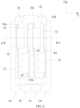
FIG. 8 is a schematic diagram of the insulation member shown inFIG. 6 . - Reference numerals are as follows:
- 1: Electrode assembly;
- 11: Body portion;
- 12: First tab;
- 13: Second tab;
- 14: First electrode plate;
- 141: First coated region;
- 142: First uncoated region;
- 15: Second electrode plate;
- 16: Separator;
- 1a: First electrode assembly;
- 1b: Second electrode assembly;
- 1c: Third electrode assembly;
- 1d: Fourth electrode assembly;
- 2: Housing;
- 3: Top cover assembly;
- 31: Top cover plate;
- 32: First electrode terminal;
- 33: Second electrode terminal;
- 4: Current collecting member;
- 41: First current collecting plate;
- 42: Second current collecting plate;
- 43: Terminal connecting plate;
- 5: Insulation member;
- 51: Substrate;
- 52: Protrusion;
- 521: First region;
- 522: Second region;
- 52a: First protrusion;
- 52b: Second protrusion;
- 52c: Third protrusion;
- 52d: Fourth protrusion;
- H: Via hole;
- S: Gap;
- S1: First gap;
- S2: Second gap;
- S3: Third gap;
- S4: Fourth gap;
- X: Transverse direction;
- Y: Longitudinal direction; and
- Z: Height direction.
- To make the objectives, technical solutions, and advantages of this application clearer, the following describes this application in further detail with reference to accompanying drawings and embodiments. Understandably, the specific embodiments described herein are merely intended to explain this application, but are not intended to limit this application.
- In the context of this application, unless otherwise expressly specified, the terms such as "first", "second", and "third" are for the sole purpose of description rather than indicating or implying any order of preference; the term "a plurality of" means two or more (including two); unless otherwise expressly specified, the term "connect" needs to be understood in a broad sense. For example, a "connection" may be a fixed connection, or a detachable connection, or an integrated connection, or an electrical connection or signal connection; or may be a direct connection or an indirect connection implemented through an intermediate medium. A person of ordinary skill in the art can understand the specific meanings of the terms in this application according to the context.
- Understandably, in the context of this application, directional terms such as "on", "above", "under", and "below" described in the embodiments of this application are described from a perspective shown in the drawings, and are not to be understood as a limitation on the embodiments of this application. The following describes this application in further detail with reference to specific embodiments and accompanying drawings.
- Referring to
FIG. 1 andFIG. 2 , a secondary battery according to this application includes anelectrode assembly 1, ahousing 2, atop cover assembly 3, acurrent collecting member 4, and aninsulation member 5. - Referring to
FIG. 3 and FIG. 4 , theelectrode assembly 1 includes afirst electrode plate 14, asecond electrode plate 15, and aseparator 16. Theseparator 16 is disposed between thefirst electrode plate 14 and thesecond electrode plate 15. Theelectrode assembly 1 is formed by spirally winding thefirst electrode plate 14, theseparator 16, and thesecond electrode plate 15, and forms a flat structure by being pressed under a pressure. Theelectrode assembly 1 is a core part for the secondary battery to implement functions of charging and discharging. - The
first electrode plate 14 includes a first current collector and a first active material layer coated on a surface of the first current collector. Thefirst electrode plate 14 may be a positive electrode plate. The first current collector is an aluminum foil. The first active material layer includes active materials such as lithium manganate and lithium iron phosphate. The active materials (such as lithium manganate and lithium iron phosphate), a binder, a conductive agent, and a solvent may be made into a slurry, and then the slurry may be coated on both surfaces of the first current collector. After the slurry is cured, the first active material layer is formed. - Merely a part of the first current collector is coated with the first active material layer. Referring to
FIG. 5 , the first active material layer and a region that is of the first current collector and coated with the first active material layer form a firstcoated region 141 of thefirst electrode plate 14. A region that is of the first current collector and not coated with the first active material layer forms a firstuncoated region 142 of thefirst electrode plate 14. The firstuncoated regions 142 may be plural in number and are spaced out. After thefirst electrode plate 14 is wound into shape, the plurality of firstuncoated regions 142 are stacked together. - The
second electrode plate 15 includes a second current collector and a second active material layer coated on a surface of the second current collector. The second active material layer and a region that is of the second current collector and coated with the second active material layer form a second coated region of thesecond electrode plate 15. The region that is of the second current collector and not coated with the second active material layer forms a second uncoated region of thesecond electrode plate 15. The second uncoated regions may be plural in number and are spaced out. After thesecond electrode plate 15 is wound into shape, the plurality of second uncoated regions are stacked together. Thesecond electrode plate 15 is similar to thefirst electrode plate 14 in structure, but differs in that the second current collector may be made of a copper foil material and the second active material layer includes an active material such as graphite or silicon. - The
separator 16 may be a polyethylene (PE) film, a polypropylene (PP) film, or a PP-PE-PP three-layered composite film. - After the
electrode assembly 1 is wound into shape, from a perspective of an appearance of theelectrode assembly 1, theelectrode assembly 1 includes abody portion 11, afirst tab 12, and asecond tab 13. Thebody portion 11 includes the firstcoated region 141, theseparator 16, and the second coated region of thesecond electrode plate 15. Thefirst tab 12 includes a plurality of firstuncoated regions 142 stacked together. Thesecond tab 13 includes a plurality of second uncoated regions stacked together. - A spool of the
electrode assembly 1 is substantially parallel to a transverse direction X. Thefirst tab 12 extends from one end of thebody portion 11 in the transverse direction X. Thesecond tab 13 extends from the other end of thebody portion 11 in the transverse direction X. - The
housing 2 may be in a hexahedral shape or another shape. Thehousing 2 forms an accommodation cavity interiorly to accommodate theelectrode assembly 1 and an electrolytic solution. Thehousing 2 forms an opening at one end, and theelectrode assembly 1 can be placed into the accommodation cavity of thehousing 2 through the opening. Thehousing 2 may be made of a conductive metal material. Preferably, thehousing 2 is made of aluminum or an aluminum alloy. - The
top cover assembly 3 includes atop cover plate 31, afirst electrode terminal 32, and asecond electrode terminal 33. Thetop cover plate 31 is disposed on thehousing 2 and covers the opening of thehousing 2 to enclose theelectrode assembly 1 in thehousing 2. Thetop cover plate 31 may be connected to thehousing 2 by welding or by other means. Thefirst electrode terminal 32 and thesecond electrode terminal 33 are disposed on thetop cover plate 31. Thefirst electrode terminal 32 is electrically connected to thefirst tab 12, and thesecond electrode terminal 33 is electrically connected to thesecond tab 13. - There may be two
current collecting members 4. Onecurrent collecting member 4 is connected to thefirst tab 12 and thefirst electrode terminal 32. The other current collectingmember 4 is connected to thesecond tab 13 and thesecond electrode terminal 33. - The
first tab 12 includes a plurality of layers of firstuncoated regions 142. The plurality of layers of firstuncoated regions 142 are welded onto the current collectingmember 4. After completion of the welding, to reduce space occupied by thefirst tab 12, thefirst tab 12 is generally bent. However, for the part located between a weld region and thebody portion 11 in the firstuncoated region 142, the plurality of layers of firstuncoated regions 142 are in a dispersed state. In a process of bending thefirst tab 12, the plurality of layers of firstuncoated regions 142 in the dispersed state lack support. Therefore, a root of each firstuncoated region 142 is very likely to be deformed and inserted inwardly into thebody portion 11, thereby causing a short-circuit risk. - Therefore, preferably, an
insulation member 5 is disposed on one side of thebody portion 11 according to this application. Referring toFIG. 6 to FIG. 8 , theinsulation member 5 is disposed between thebody portion 11 and the current collectingmember 4, and theinsulation member 5 includes a through gap S. The gap S may be slit-shaped. - The
first tab 12 passes through the gap S and is connected to the current collectingmember 4. The part at which thefirst tab 12 passes through the gap S may be welded to the current collectingmember 4. The gap S can tuck the plurality of layers of firstuncoated regions 142 of thefirst tab 12 together. - In this application, the gap S of the
insulation member 5 can tuck thefirst tab 12 and restrain thefirst tab 12 from deforming in a process of bending thefirst tab 12, thereby reducing risks of inserting the root of thefirst tab 12 into thebody portion 11, avoiding a short circuit, and improving safety performance. - The
insulation member 5 may be fixed to the current collectingmember 4 to prevent theinsulation member 5 from shaking in the secondary battery. For example, theinsulation member 5 may be bonded to the current collectingmember 4. - The
insulation member 5 includes asubstrate 51 and aprotrusion 52. Theprotrusion 52 extends from a surface of thesubstrate 51, the surface being away from thebody portion 11 in the transverse direction X. Thesubstrate 51 is approximately a flat plate perpendicular to the transverse direction X. The gap S extends from a surface of theprotrusion 52 and runs through theprotrusion 52 and thesubstrate 51, the surface being away from thesubstrate 51. Theprotrusion 52 disposed can increase a depth of the gap S in the transverse direction X, so as to increase the ability of the gap S to tuck thefirst tab 12. - The
current collecting member 4 includes a first current collectingplate 41 and aterminal connecting plate 43. The first current collectingplate 41 extends in a direction approximately perpendicular to the transverse direction X. The first current collectingplate 41 is located on a side of thesubstrate 51, the side being away from thebody portion 11. Theterminal connecting plate 43 is bent against the first current collectingplate 41, and connects the first current collectingplate 41 and thefirst electrode terminal 32. Theterminal connecting plate 43 may be located above thesubstrate 51 in a height direction Z. - The first current collecting
plate 41 fits snugly with thebody portion 11. Preferably, the first current collectingplate 41 is bonded to thebody portion 11. - The
protrusion 52 is located at a lateral position of the first current collectingplate 41 in a longitudinal direction Y. This avoids superimposing theprotrusion 52 on the first current collectingplate 41 in the transverse direction X, reduces the space occupied by theinsulation member 5 and the current collectingmember 4 in the transverse direction X, and increases the energy density. - The first current collecting
plate 41 is connected to thefirst tab 12. After passing through the gap S, thefirst tab 12 may be connected to the first current collectingplate 41 by ultrasonic welding. - Referring to
FIG. 7 , in the transverse direction X, a thickness of theprotrusion 52 is less than or equal to a thickness of the first current collectingplate 41. This prevents theprotrusion 52 from occupying additional space in the transverse direction X. - Referring to
FIG. 6 andFIG. 8 , theprotrusion 52 of theinsulation member 5 is plural in number, and the plurality ofprotrusions 52 include afirst protrusion 52a and asecond protrusion 52b arranged in the longitudinal direction Y. The first current collectingplate 41 is located between thefirst protrusion 52a and thesecond protrusion 52b. Thefirst protrusion 52a and thesecond protrusion 52b can support the first current collectingplate 41 from both sides, restrain the first current collectingplate 41 from shaking, and reduce risks of rupturing thefirst tab 12. In addition, thefirst protrusion 52a and thesecond protrusion 52b also help to position and assemble the first current collectingplate 41. - To increase a capacity of the secondary battery, a plurality of
electrode assemblies 1 are generally disposed. If thefirst tabs 12 of the plurality ofelectrode assemblies 1 pass through an identical gap S, the plurality offirst tabs 12 may be rather staggered, thereby making it more difficult to tuck thefirst tabs 12. - Therefore, preferably, a plurality of gaps S are disposed. The plurality of gaps S include a first gap S1 and a second gap S2. The first gap S1 runs through the
first protrusion 52a and thesubstrate 51. The second gap S2 runs through thesecond protrusion 52b and thesubstrate 51. - The plurality of
electrode assemblies 1 include a first electrode assembly 1a and asecond electrode assembly 1b. Thefirst tab 12 of the first electrode assembly 1a passes through the first gap S1 and is connected to the first current collectingplate 41. Thefirst tab 12 of thesecond electrode assembly 1b passes through the second gap S2 and is connected to the first current collectingplate 41. - In the height direction Z, the first gap S1 and the second gap S2 are staggered. In other words, in the height direction Z, the first gap S1 and the second gap S2 are at different heights. The
first tab 12 passing through the first gap S1 is bent toward a side close to thesecond electrode assembly 1b and is connected to the first current collectingplate 41. Thefirst tab 12 passing through the second gap S2 is bent toward a side close to the first electrode assembly 1a and is connected to the first current collectingplate 41. - If the
first tab 12 of the first electrode assembly 1a is flush with thefirst tab 12 of thesecond electrode assembly 1b in the height direction Z, thefirst tab 12 of the first electrode assembly 1a and thefirst tab 12 of thesecond electrode assembly 1b are likely to be stacked together. This increases the difficulty of welding and causes risks of poor welding. However, in this application, the first gap S1 and the second gap S2 are staggered longitudinally. Therefore, thefirst tab 12 of the first electrode assembly 1a and thefirst tab 12 of thesecond electrode assembly 1b can be staggered longitudinally to avoid stacking thefirst tab 12 of the first electrode assembly 1a and thefirst tab 12 of thesecond electrode assembly 1b together and reduce risks of poor welding. - Referring to
FIG. 6 andFIG. 8 , eachprotrusion 52 includes afirst region 521 and asecond region 522. Thefirst region 521 and thesecond region 522 are arranged along the height direction Z. In the longitudinal direction Y, a width of thefirst region 521 is greater than a width of thesecond region 522. The first gap S1 runs through thefirst region 521 of thefirst protrusion 52a. The second gap S2 runs through thefirst region 521 of thesecond protrusion 52b. - In this application, the width of the
first region 521 is increased so that it is convenient to open the gap S in thefirst region 521. For thesecond region 522 in which no gap S needs to be opened, the width of thesecond region 522 may be reduced appropriately to reduce the space occupied by thesecond region 522 and increase the energy density. - Along the height direction Z, an arrangement direction of the
first region 521 and thesecond region 522 of thefirst protrusion 52a is opposite to an arrangement direction of thefirst region 521 and thesecond region 522 of thesecond protrusion 52b. This causes the first gap S1 and the second gap S2 to be staggered longitudinally. - In the longitudinal direction Y, an edge that is of the
first region 521 and close to the first current collectingplate 41 is flush with an edge that is of thesecond region 522 and close to the first current collectingplate 41. The flush arranged edges of thefirst region 521 and thesecond region 522 can more effectively support the first current collectingplate 41 and retrain the first current collectingplate 41 from shaking in the longitudinal direction Y. - A via hole H is disposed in the
body portion 11. The via hole H is formed on at least one side of thefirst protrusion 52a, the side being away from the first current collectingplate 41. An electrolytic solution inside thehousing 2 can freely pass through the via hole H, thereby ensuring high infiltration performance of the electrolytic solution and increasing a cycle life. Preferably, the via hole H is further formed on a side of thesecond protrusion 52b, the side being away from the first current collectingplate 41. - The plurality of
electrode assemblies 1 include athird electrode assembly 1c and afourth electrode assembly 1d. Preferably, the current collectingmember 4 further includes a second current collectingplate 42. The second current collectingplate 42 electrically connects thethird electrode assembly 1c and thefourth electrode assembly 1d to thefirst electrode terminal 32. - The plurality of
protrusions 52 include athird protrusion 52c and afourth protrusion 52d. Thefirst protrusion 52a, thesecond protrusion 52b, thethird protrusion 52c, and thefourth protrusion 52d are arranged sequentially along the longitudinal direction Y. The second current collectingplate 42 is located between thethird protrusion 52c and thefourth protrusion 52d. Thethird protrusion 52c and thefourth protrusion 52d support the second current collectingplate 42 from both sides, restrain the second current collectingplate 42 from shaking, and reduce risks of rupturing thefirst tab 12. In addition, thethird protrusion 52c and thefourth protrusion 52d also help to position and assemble the second current collectingplate 42. - The plurality of gaps S further include a third gap S3 and a fourth gap S4. The third gap S3 runs through the
third protrusion 52c and thesubstrate 51. The fourth gap S4 runs through thefourth protrusion 52d and thesubstrate 51. - The
first tab 12 of thethird electrode assembly 1c passes through the third gap S3 and is connected to the second current collectingplate 42. Thefirst tab 12 of thefourth electrode assembly 1d passes through the fourth gap S4 and is connected to the second current collectingplate 42. - A shape of the
third protrusion 52c is identical to a shape of thefirst protrusion 52a, and a shape of thefourth protrusion 52d is identical to a shape of thesecond protrusion 52b. In the height direction Z, the third gap S3 and the fourth gap S4 are staggered. The via hole H is further formed between thesecond protrusion 52b and thethird protrusion 52c. - Further aspects of the present invention are provided in the following clauses.
-
Clause 1. A secondary battery, characterized in that: the secondary battery comprises an electrode assembly (1), a housing (2), a top cover assembly (3), a current collecting member (4), and an insulation member (5); the electrode assembly (1) is accommodated in the housing (2) and comprises a body portion (11) and a first tab (12), and the first tab (12) extends from one end of the body portion (11) in a transverse direction (X); the top cover assembly (3) comprises a top cover plate (31) and a first electrode terminal (32) disposed on the top cover plate (31), the top cover plate (31) is connected to the housing (2), and the first electrode terminal (32) is connected to the current collecting member (4); the insulation member (5) is disposed between the body portion (11) and the current collecting member (4), and the insulation member (5) comprises a through gap (S); and the first tab (12) passes through the gap (S) and is connected to the current collecting member (4). -
Clause 2. The secondary battery according toclause 1, characterized in that: the insulation member (5) comprises a substrate (51) and a protrusion (52), and the protrusion (52) extends from a surface of the substrate (51), the surface being away from the body portion (11) in the transverse direction (X); the gap (S) extends from a surface of the protrusion (52) and runs through the protrusion (52) and the substrate (51), the surface being away from the substrate (51); the current collecting member (4) comprises a first current collecting plate (41), and the first current collecting plate (41) is located on a side of the substrate (51) and fits snugly with the body portion (11), the side being away from the body portion (11); and the protrusion (52) is located at a lateral position of the first current collecting plate (41) in a longitudinal direction (Y); and the first current collecting plate (41) is connected to the first tab (12). -
Clause 3. The secondary battery according toclause 2, characterized in that, in the transverse direction (X), a thickness of the protrusion (52) is less than or equal to a thickness of the first current collecting plate (41). -
Clause 4. The secondary battery according to clause 2 or 3, characterized in that: the protrusion (52) of the insulation member (5) is plural in number, and the plurality of protrusions (52) comprise a first protrusion (52a) and a second protrusion (52b) arranged in the longitudinal direction (Y); the first current collecting plate (41) is located between the first protrusion (52a) and the second protrusion (52b); the gap (S) is plural in number, the plurality of gaps (S) comprise a first gap (S1) and a second gap (S2), the first gap (S1) runs through the first protrusion (52a) and the substrate (51), and the second gap (S2) runs through the second protrusion (52b) and the substrate (51); and the electrode assembly (1) is plural in number, the plurality of electrode assemblies (1) comprise a first electrode assembly (1a) and a second electrode assembly (1b), the first tab (12) of the first electrode assembly (1a) passes through the first gap (S1) and is connected to the first current collecting plate (41), and the first tab (12) of the second electrode assembly (1b) passes through the second gap (S2) and is connected to the first current collecting plate (41). -
Clause 5. The secondary battery according toclause 4, characterized in that: in a height direction (Z), the first gap (S1) and the second gap (S2) are staggered; the first tab (12) passing through the first gap (S1) is bent toward a side close to the second electrode assembly (1b) and is connected to the first current collecting plate (41), and the first tab (12) passing through the second gap (S2) is bent toward a side close to the first electrode assembly (1a) and is connected to the first current collecting plate (41). - Clause 6. The secondary battery according to
clause - Clause 7: The secondary battery according to clause 6, characterized in that, in the longitudinal direction (Y), an edge that is of the first region (521) and close to the first current collecting plate (41) is flush with an edge that is of the second region (522) and close to the first current collecting plate (41).
- Clause 8. The secondary battery according to any one of
clauses 4 to 7, characterized in that a via hole (H) is disposed in the body portion (11), and the via hole (H) is formed on at least one side of the first protrusion (52a), the side being away from the first current collecting plate (41). - Clause 9. The secondary battery according to any one of clauses 4 to 8, characterized in that: the plurality of protrusions (52) comprise a third protrusion (52c) and a fourth protrusion (52d), the first protrusion (52a), the second protrusion (52b), the third protrusion (52c) and the fourth protrusion (52d) are arranged sequentially along the longitudinal direction (Y); the current collecting member (4) further comprises a second current collecting plate (42), and the second current collecting plate (42) is located between the third protrusion (52c) and the fourth protrusion (52d); the plurality of gaps (S) further comprise a third gap (S3) and a fourth gap (S4), the third gap (S3) runs through the third protrusion (52c) and the substrate (51), and the fourth gap (S4) runs through the fourth protrusion (52d) and the substrate (51); and the plurality of electrode assemblies (1) comprise a third electrode assembly (1c) and a fourth electrode assembly (1d), the first tab (12) of the third electrode assembly (1c) passes through the third gap (S3) and is connected to the second current collecting plate (42), and the first tab (12) of the fourth electrode assembly (1d) passes through the fourth gap (S4) and is connected to the second current collecting plate (42).
- Clause 10. The secondary battery according to any one of
clauses 1 to 9, characterized in that the insulation member (5) is bonded to the current collecting member (4).
Claims (9)
- A secondary battery, characterized in that the secondary battery comprises an electrode assembly (1), a housing (2), a top cover assembly (3), a current collecting member (4), and an insulation member (5);the electrode assembly (1) is accommodated in the housing (2) and comprises a body portion (11) and a first tab (12), and the first tab (12) extends from one end of the body portion (11) in a transverse direction (X);the top cover assembly (3) comprises a top cover plate (31) and a first electrode terminal (32) disposed on the top cover plate (31), the top cover plate (31) is connected to the housing (2), and the first electrode terminal (32) is connected to the current collecting member (4);the insulation member (5) is disposed between the body portion (11) and the current collecting member (4), and the insulation member (5) comprises a through gap (S); andthe first tab (12) passes through the gap (S) and is connected to the current collecting member (4);whereinthe insulation member (5) comprises a substrate (51) and a protrusion (52), and the protrusion (52) extends from a surface of the substrate (51), the surface being away from the body portion (11) in the transverse direction (X);the gap (S) extends from a surface of the protrusion (52) and runs through the protrusion (52) and the substrate (51), the surface being away from the substrate (51);the current collecting member (4) comprises a first current collecting plate (41), and the first current collecting plate (41) is located on a side of the substrate (51) and fits snugly with the body portion (11), the side being away from the body portion (11); and the protrusion (52) is located at a lateral position of the first current collecting plate (41) in a longitudinal direction (Y); andthe first current collecting plate (41) is connected to the first tab (12).
- The secondary battery according to claim 1, characterized in that, in the transverse direction (X), a thickness of the protrusion (52) is less than or equal to a thickness of the first current collecting plate (41).
- The secondary battery according to claim 1 or 2, characterized in thatthe protrusion (52) of the insulation member (5) is plural in number, and the plurality of protrusions (52) comprise a first protrusion (52a) and a second protrusion (52b) arranged in the longitudinal direction (Y);the first current collecting plate (41) is located between the first protrusion (52a) and the second protrusion (52b);the gap (S) is plural in number, the plurality of gaps (S) comprise a first gap (S1) and a second gap (S2), the first gap (S1) runs through the first protrusion (52a) and the substrate (51), and the second gap (S2) runs through the second protrusion (52b) and the substrate (51); andthe electrode assembly (1) is plural in number, the plurality of electrode assemblies (1) comprise a first electrode assembly (1a) and a second electrode assembly (1b), the first tab (12) of the first electrode assembly (1a) passes through the first gap (S1) and is connected to the first current collecting plate (41), and the first tab (12) of the second electrode assembly (1b) passes through the second gap (S2) and is connected to the first current collecting plate (41).
- The secondary battery according to claim 3, characterized in thatin a height direction (Z), the first gap (S1) and the second gap (S2) are staggered;the first tab (12) passing through the first gap (S1) is bent toward a side close to the second electrode assembly (1b) and is connected to the first current collecting plate (41), and the first tab (12) passing through the second gap (S2) is bent toward a side close to the first electrode assembly (1a) and is connected to the first current collecting plate (41).
- The secondary battery according to claim 4, characterized in thateach protrusion (52) comprises a first region (521) and a second region (522), and the first region (521) and the second region (522) are arranged along a height direction (Z); in the longitudinal direction (Y), a width of the first region (521) is greater than a width of the second region (522);the first gap (S1) runs through the first region (521) of the first protrusion (52a), and the second gap (S2) runs through the first region (521) of the second protrusion (52b); andalong the height direction (Z), an arrangement direction of the first region (521) and the second region (522) of the first protrusion (52a) is opposite to an arrangement direction of the first region (521) and the second region (522) of the second protrusion (52b).
- The secondary battery according to claim 4, characterized in that, in the longitudinal direction (Y), an edge that is of the first region (521) and close to the first current collecting plate (41) is flush with an edge that is of the second region (522) and close to the first current collecting plate (41).
- The secondary battery according to any one of claims 3 to 6, characterized in that a via hole (H) is disposed in the body portion (11), and the via hole (H) is formed on at least one side of the first protrusion (52a), the side being away from the first current collecting plate (41).
- The secondary battery according to any one of claims 3 to 7, characterized in thatthe plurality of protrusions (52) comprise a third protrusion (52c) and a fourth protrusion (52d), the first protrusion (52a), the second protrusion (52b), the third protrusion (52c) and the fourth protrusion (52d) are arranged sequentially along the longitudinal direction (Y);the current collecting member (4) further comprises a second current collecting plate (42), and the second current collecting plate (42) is located between the third protrusion (52c) and the fourth protrusion (52d);the plurality of gaps (S) further comprise a third gap (S3) and a fourth gap (S4), the third gap (S3) runs through the third protrusion (52c) and the substrate (51), and the fourth gap (S4) runs through the fourth protrusion (52d) and the substrate (51); andthe plurality of electrode assemblies (1) comprise a third electrode assembly (1c) and a fourth electrode assembly (1d), the first tab (12) of the third electrode assembly (1c) passes through the third gap (S3) and is connected to the second current collecting plate (42), and the first tab (12) of the fourth electrode assembly (1d) passes through the fourth gap (S4) and is connected to the second current collecting plate (42).
- The secondary battery according to any one of claims 1 to 8, characterized in that the insulation member (5) is bonded to the current collecting member (4).
Applications Claiming Priority (3)
| Application Number | Priority Date | Filing Date | Title |
|---|---|---|---|
| CN201921309828.XU CN210136894U (en) | 2019-08-13 | 2019-08-13 | Secondary battery |
| EP20853108.7A EP3934013B1 (en) | 2019-08-13 | 2020-07-26 | Secondary battery |
| PCT/CN2020/104706 WO2021027535A1 (en) | 2019-08-13 | 2020-07-26 | Secondary battery |
Related Parent Applications (2)
| Application Number | Title | Priority Date | Filing Date |
|---|---|---|---|
| EP20853108.7A Division-Into EP3934013B1 (en) | 2019-08-13 | 2020-07-26 | Secondary battery |
| EP20853108.7A Division EP3934013B1 (en) | 2019-08-13 | 2020-07-26 | Secondary battery |
Publications (3)
| Publication Number | Publication Date |
|---|---|
| EP4379912A1 true EP4379912A1 (en) | 2024-06-05 |
| EP4379912C0 EP4379912C0 (en) | 2025-12-03 |
| EP4379912B1 EP4379912B1 (en) | 2025-12-03 |
Family
ID=69708173
Family Applications (2)
| Application Number | Title | Priority Date | Filing Date |
|---|---|---|---|
| EP20853108.7A Active EP3934013B1 (en) | 2019-08-13 | 2020-07-26 | Secondary battery |
| EP24171316.3A Active EP4379912B1 (en) | 2019-08-13 | 2020-07-26 | Secondary battery |
Family Applications Before (1)
| Application Number | Title | Priority Date | Filing Date |
|---|---|---|---|
| EP20853108.7A Active EP3934013B1 (en) | 2019-08-13 | 2020-07-26 | Secondary battery |
Country Status (4)
| Country | Link |
|---|---|
| US (1) | US12315959B2 (en) |
| EP (2) | EP3934013B1 (en) |
| CN (1) | CN210136894U (en) |
| WO (1) | WO2021027535A1 (en) |
Families Citing this family (6)
| Publication number | Priority date | Publication date | Assignee | Title |
|---|---|---|---|---|
| CN210136894U (en) | 2019-08-13 | 2020-03-10 | 宁德时代新能源科技股份有限公司 | Secondary battery |
| CN113629300A (en) * | 2021-08-30 | 2021-11-09 | 苏州领湃新能源科技有限公司 | Lithium-ion power battery |
| CN115064701B (en) * | 2022-05-20 | 2025-02-11 | 远景动力技术(江苏)有限公司 | Current collecting component and battery manufacturing method |
| CN118263627A (en) * | 2022-12-27 | 2024-06-28 | 厦门海辰储能科技股份有限公司 | Battery, battery pack and electric equipment |
| CN219180724U (en) * | 2022-12-27 | 2023-06-13 | 厦门海辰储能科技股份有限公司 | Battery, battery pack and electric equipment |
| EP4648184A1 (en) * | 2024-05-10 | 2025-11-12 | Volvo Car Corporation | Battery cell for a vehicle |
Citations (2)
| Publication number | Priority date | Publication date | Assignee | Title |
|---|---|---|---|---|
| CN207938699U (en) * | 2018-01-31 | 2018-10-02 | 比亚迪股份有限公司 | Battery Spacers and Batteries |
| CN208298915U (en) * | 2018-02-06 | 2018-12-28 | 比亚迪股份有限公司 | The spacer ring and battery of battery |
Family Cites Families (8)
| Publication number | Priority date | Publication date | Assignee | Title |
|---|---|---|---|---|
| JP2014203514A (en) * | 2013-04-01 | 2014-10-27 | 三洋電機株式会社 | Battery |
| CN206076349U (en) * | 2016-08-16 | 2017-04-05 | 宁德时代新能源科技股份有限公司 | Electric connecting sheet and battery modules |
| JP6782136B2 (en) * | 2016-09-26 | 2020-11-11 | 株式会社エンビジョンAescジャパン | Spacer and battery pack |
| KR102571487B1 (en) * | 2017-08-31 | 2023-08-28 | 삼성에스디아이 주식회사 | Secondary Battery And Assembling Method thereof |
| CN207690902U (en) * | 2017-12-14 | 2018-08-03 | 比亚迪股份有限公司 | Battery and the battery pack with it, electric vehicle |
| CN207818740U (en) * | 2018-02-09 | 2018-09-04 | 宁德时代新能源科技股份有限公司 | Battery module connector and battery module |
| CN208819970U (en) * | 2018-10-26 | 2019-05-03 | 宁德时代新能源科技股份有限公司 | Secondary battery |
| CN210136894U (en) * | 2019-08-13 | 2020-03-10 | 宁德时代新能源科技股份有限公司 | Secondary battery |
-
2019
- 2019-08-13 CN CN201921309828.XU patent/CN210136894U/en active Active
-
2020
- 2020-07-26 WO PCT/CN2020/104706 patent/WO2021027535A1/en not_active Ceased
- 2020-07-26 EP EP20853108.7A patent/EP3934013B1/en active Active
- 2020-07-26 EP EP24171316.3A patent/EP4379912B1/en active Active
-
2021
- 2021-12-21 US US17/557,172 patent/US12315959B2/en active Active
Patent Citations (2)
| Publication number | Priority date | Publication date | Assignee | Title |
|---|---|---|---|---|
| CN207938699U (en) * | 2018-01-31 | 2018-10-02 | 比亚迪股份有限公司 | Battery Spacers and Batteries |
| CN208298915U (en) * | 2018-02-06 | 2018-12-28 | 比亚迪股份有限公司 | The spacer ring and battery of battery |
Also Published As
| Publication number | Publication date |
|---|---|
| EP4379912C0 (en) | 2025-12-03 |
| WO2021027535A1 (en) | 2021-02-18 |
| EP3934013B1 (en) | 2024-06-12 |
| US12315959B2 (en) | 2025-05-27 |
| EP3934013A4 (en) | 2022-06-08 |
| EP3934013C0 (en) | 2024-06-12 |
| CN210136894U (en) | 2020-03-10 |
| EP3934013A1 (en) | 2022-01-05 |
| US20220115751A1 (en) | 2022-04-14 |
| EP4379912B1 (en) | 2025-12-03 |
Similar Documents
| Publication | Publication Date | Title |
|---|---|---|
| US12315959B2 (en) | Secondary battery comprising insulation member | |
| EP3852165B1 (en) | Secondary battery and manufacturing method for secondary battery | |
| EP3451416B1 (en) | Second battery | |
| EP2498318B1 (en) | Battery pack | |
| JP5543943B2 (en) | Secondary battery | |
| EP3940854B1 (en) | Electrode assembly, secondary battery, and apparatus using battery | |
| KR101147207B1 (en) | Electrode assembly, and rechargeable battery using thereof | |
| JP2011060767A (en) | Secondary battery | |
| EP3067958B1 (en) | Electrode assembly and secondary battery having the electrode assembly | |
| JP2006093100A (en) | Secondary battery | |
| EP2736102B1 (en) | Electrode assembly and rechargeable battery having the same | |
| CN116885294A (en) | Secondary batteries and electronic devices | |
| CN209104259U (en) | Secondary battery | |
| KR20000021401A (en) | Method for manufacturing electrode assembly unit and the electrode assembly unit and battery using the electrode assembly | |
| US20220158278A1 (en) | Rechargeable battery | |
| CN209104247U (en) | Secondary battery | |
| KR100696844B1 (en) | Secondary battery | |
| CN112786947A (en) | Battery roll core structure and battery monomer | |
| EP4712182A1 (en) | Current collector and battery | |
| KR102952071B1 (en) | Electrode assembly of rechargeable battery | |
| JP2021026911A (en) | Electrical storage device | |
| EP4576352A1 (en) | Rechargeable battery | |
| EP4726830A1 (en) | Secondary batteries and a manufacturing method thereof | |
| EP4715968A1 (en) | Secondary battery and method of manufacturing same | |
| KR100709862B1 (en) | Cylindrical secondary battery |
Legal Events
| Date | Code | Title | Description |
|---|---|---|---|
| PUAI | Public reference made under article 153(3) epc to a published international application that has entered the european phase |
Free format text: ORIGINAL CODE: 0009012 |
|
| STAA | Information on the status of an ep patent application or granted ep patent |
Free format text: STATUS: THE APPLICATION HAS BEEN PUBLISHED |
|
| AC | Divisional application: reference to earlier application |
Ref document number: 3934013 Country of ref document: EP Kind code of ref document: P |
|
| AK | Designated contracting states |
Kind code of ref document: A1 Designated state(s): AL AT BE BG CH CY CZ DE DK EE ES FI FR GB GR HR HU IE IS IT LI LT LU LV MC MK MT NL NO PL PT RO RS SE SI SK SM TR |
|
| RAP1 | Party data changed (applicant data changed or rights of an application transferred) |
Owner name: CONTEMPORARY AMPEREX TECHNOLOGY(HONG KONG) LIMITED |
|
| STAA | Information on the status of an ep patent application or granted ep patent |
Free format text: STATUS: REQUEST FOR EXAMINATION WAS MADE |
|
| 17P | Request for examination filed |
Effective date: 20241204 |
|
| GRAJ | Information related to disapproval of communication of intention to grant by the applicant or resumption of examination proceedings by the epo deleted |
Free format text: ORIGINAL CODE: EPIDOSDIGR1 |
|
| GRAP | Despatch of communication of intention to grant a patent |
Free format text: ORIGINAL CODE: EPIDOSNIGR1 |
|
| GRAP | Despatch of communication of intention to grant a patent |
Free format text: ORIGINAL CODE: EPIDOSNIGR1 |
|
| STAA | Information on the status of an ep patent application or granted ep patent |
Free format text: STATUS: GRANT OF PATENT IS INTENDED |
|
| INTG | Intention to grant announced |
Effective date: 20250909 |
|
| GRAS | Grant fee paid |
Free format text: ORIGINAL CODE: EPIDOSNIGR3 |
|
| GRAA | (expected) grant |
Free format text: ORIGINAL CODE: 0009210 |
|
| STAA | Information on the status of an ep patent application or granted ep patent |
Free format text: STATUS: THE PATENT HAS BEEN GRANTED |
|
| AC | Divisional application: reference to earlier application |
Ref document number: 3934013 Country of ref document: EP Kind code of ref document: P |
|
| AK | Designated contracting states |
Kind code of ref document: B1 Designated state(s): AL AT BE BG CH CY CZ DE DK EE ES FI FR GB GR HR HU IE IS IT LI LT LU LV MC MK MT NL NO PL PT RO RS SE SI SK SM TR |
|
| REG | Reference to a national code |
Ref country code: CH Ref legal event code: F10 Free format text: ST27 STATUS EVENT CODE: U-0-0-F10-F00 (AS PROVIDED BY THE NATIONAL OFFICE) Effective date: 20251203 Ref country code: GB Ref legal event code: FG4D |
|
| REG | Reference to a national code |
Ref country code: DE Ref legal event code: R096 Ref document number: 602020063517 Country of ref document: DE |
|
| REG | Reference to a national code |
Ref country code: IE Ref legal event code: FG4D |
|
| U01 | Request for unitary effect filed |
Effective date: 20251223 |
|
| U07 | Unitary effect registered |
Designated state(s): AT BE BG DE DK EE FI FR IT LT LU LV MT NL PT RO SE SI Effective date: 20260109 |
|
| PG25 | Lapsed in a contracting state [announced via postgrant information from national office to epo] |
Ref country code: ES Free format text: LAPSE BECAUSE OF FAILURE TO SUBMIT A TRANSLATION OF THE DESCRIPTION OR TO PAY THE FEE WITHIN THE PRESCRIBED TIME-LIMIT Effective date: 20251203 |
|
| PG25 | Lapsed in a contracting state [announced via postgrant information from national office to epo] |
Ref country code: NO Free format text: LAPSE BECAUSE OF FAILURE TO SUBMIT A TRANSLATION OF THE DESCRIPTION OR TO PAY THE FEE WITHIN THE PRESCRIBED TIME-LIMIT Effective date: 20260303 |
|
| PG25 | Lapsed in a contracting state [announced via postgrant information from national office to epo] |
Ref country code: HR Free format text: LAPSE BECAUSE OF FAILURE TO SUBMIT A TRANSLATION OF THE DESCRIPTION OR TO PAY THE FEE WITHIN THE PRESCRIBED TIME-LIMIT Effective date: 20251203 |
|
| PG25 | Lapsed in a contracting state [announced via postgrant information from national office to epo] |
Ref country code: RS Free format text: LAPSE BECAUSE OF FAILURE TO SUBMIT A TRANSLATION OF THE DESCRIPTION OR TO PAY THE FEE WITHIN THE PRESCRIBED TIME-LIMIT Effective date: 20260303 |
|
| PG25 | Lapsed in a contracting state [announced via postgrant information from national office to epo] |
Ref country code: PL Free format text: LAPSE BECAUSE OF FAILURE TO SUBMIT A TRANSLATION OF THE DESCRIPTION OR TO PAY THE FEE WITHIN THE PRESCRIBED TIME-LIMIT Effective date: 20251203 |