EP4379909A1 - Battery module, and battery pack and vehicle comprising same - Google Patents
Battery module, and battery pack and vehicle comprising same Download PDFInfo
- Publication number
- EP4379909A1 EP4379909A1 EP22919064.0A EP22919064A EP4379909A1 EP 4379909 A1 EP4379909 A1 EP 4379909A1 EP 22919064 A EP22919064 A EP 22919064A EP 4379909 A1 EP4379909 A1 EP 4379909A1
- Authority
- EP
- European Patent Office
- Prior art keywords
- electrical
- cooling
- battery
- block
- battery module
- Prior art date
- Legal status (The legal status is an assumption and is not a legal conclusion. Google has not performed a legal analysis and makes no representation as to the accuracy of the status listed.)
- Pending
Links
Images



Classifications
-
- H—ELECTRICITY
- H01—ELECTRIC ELEMENTS
- H01M—PROCESSES OR MEANS, e.g. BATTERIES, FOR THE DIRECT CONVERSION OF CHEMICAL ENERGY INTO ELECTRICAL ENERGY
- H01M10/00—Secondary cells; Manufacture thereof
- H01M10/60—Heating or cooling; Temperature control
- H01M10/65—Means for temperature control structurally associated with the cells
- H01M10/655—Solid structures for heat exchange or heat conduction
- H01M10/6556—Solid parts with flow channel passages or pipes for heat exchange
-
- H—ELECTRICITY
- H01—ELECTRIC ELEMENTS
- H01M—PROCESSES OR MEANS, e.g. BATTERIES, FOR THE DIRECT CONVERSION OF CHEMICAL ENERGY INTO ELECTRICAL ENERGY
- H01M10/00—Secondary cells; Manufacture thereof
- H01M10/60—Heating or cooling; Temperature control
- H01M10/61—Types of temperature control
- H01M10/613—Cooling or keeping cold
-
- H—ELECTRICITY
- H01—ELECTRIC ELEMENTS
- H01M—PROCESSES OR MEANS, e.g. BATTERIES, FOR THE DIRECT CONVERSION OF CHEMICAL ENERGY INTO ELECTRICAL ENERGY
- H01M10/00—Secondary cells; Manufacture thereof
- H01M10/60—Heating or cooling; Temperature control
- H01M10/62—Heating or cooling; Temperature control specially adapted for specific applications
- H01M10/625—Vehicles
-
- H—ELECTRICITY
- H01—ELECTRIC ELEMENTS
- H01M—PROCESSES OR MEANS, e.g. BATTERIES, FOR THE DIRECT CONVERSION OF CHEMICAL ENERGY INTO ELECTRICAL ENERGY
- H01M10/00—Secondary cells; Manufacture thereof
- H01M10/60—Heating or cooling; Temperature control
- H01M10/64—Heating or cooling; Temperature control characterised by the shape of the cells
- H01M10/647—Prismatic or flat cells, e.g. pouch cells
-
- H—ELECTRICITY
- H01—ELECTRIC ELEMENTS
- H01M—PROCESSES OR MEANS, e.g. BATTERIES, FOR THE DIRECT CONVERSION OF CHEMICAL ENERGY INTO ELECTRICAL ENERGY
- H01M10/00—Secondary cells; Manufacture thereof
- H01M10/60—Heating or cooling; Temperature control
- H01M10/65—Means for temperature control structurally associated with the cells
- H01M10/656—Means for temperature control structurally associated with the cells characterised by the type of heat-exchange fluid
- H01M10/6567—Liquids
-
- H—ELECTRICITY
- H01—ELECTRIC ELEMENTS
- H01M—PROCESSES OR MEANS, e.g. BATTERIES, FOR THE DIRECT CONVERSION OF CHEMICAL ENERGY INTO ELECTRICAL ENERGY
- H01M50/00—Constructional details or processes of manufacture of the non-active parts of electrochemical cells other than fuel cells, e.g. hybrid cells
- H01M50/20—Mountings; Secondary casings or frames; Racks, modules or packs; Suspension devices; Shock absorbers; Transport or carrying devices; Holders
- H01M50/202—Casings or frames around the primary casing of a single cell or a single battery
-
- H—ELECTRICITY
- H01—ELECTRIC ELEMENTS
- H01M—PROCESSES OR MEANS, e.g. BATTERIES, FOR THE DIRECT CONVERSION OF CHEMICAL ENERGY INTO ELECTRICAL ENERGY
- H01M50/00—Constructional details or processes of manufacture of the non-active parts of electrochemical cells other than fuel cells, e.g. hybrid cells
- H01M50/20—Mountings; Secondary casings or frames; Racks, modules or packs; Suspension devices; Shock absorbers; Transport or carrying devices; Holders
- H01M50/204—Racks, modules or packs for multiple batteries or multiple cells
- H01M50/207—Racks, modules or packs for multiple batteries or multiple cells characterised by their shape
- H01M50/209—Racks, modules or packs for multiple batteries or multiple cells characterised by their shape adapted for prismatic or rectangular cells
-
- H—ELECTRICITY
- H01—ELECTRIC ELEMENTS
- H01M—PROCESSES OR MEANS, e.g. BATTERIES, FOR THE DIRECT CONVERSION OF CHEMICAL ENERGY INTO ELECTRICAL ENERGY
- H01M50/00—Constructional details or processes of manufacture of the non-active parts of electrochemical cells other than fuel cells, e.g. hybrid cells
- H01M50/20—Mountings; Secondary casings or frames; Racks, modules or packs; Suspension devices; Shock absorbers; Transport or carrying devices; Holders
- H01M50/244—Secondary casings; Racks; Suspension devices; Carrying devices; Holders characterised by their mounting method
-
- H—ELECTRICITY
- H01—ELECTRIC ELEMENTS
- H01M—PROCESSES OR MEANS, e.g. BATTERIES, FOR THE DIRECT CONVERSION OF CHEMICAL ENERGY INTO ELECTRICAL ENERGY
- H01M50/00—Constructional details or processes of manufacture of the non-active parts of electrochemical cells other than fuel cells, e.g. hybrid cells
- H01M50/20—Mountings; Secondary casings or frames; Racks, modules or packs; Suspension devices; Shock absorbers; Transport or carrying devices; Holders
- H01M50/249—Mountings; Secondary casings or frames; Racks, modules or packs; Suspension devices; Shock absorbers; Transport or carrying devices; Holders specially adapted for aircraft or vehicles, e.g. cars or trains
-
- H—ELECTRICITY
- H01—ELECTRIC ELEMENTS
- H01M—PROCESSES OR MEANS, e.g. BATTERIES, FOR THE DIRECT CONVERSION OF CHEMICAL ENERGY INTO ELECTRICAL ENERGY
- H01M50/00—Constructional details or processes of manufacture of the non-active parts of electrochemical cells other than fuel cells, e.g. hybrid cells
- H01M50/20—Mountings; Secondary casings or frames; Racks, modules or packs; Suspension devices; Shock absorbers; Transport or carrying devices; Holders
- H01M50/271—Lids or covers for the racks or secondary casings
-
- H—ELECTRICITY
- H01—ELECTRIC ELEMENTS
- H01M—PROCESSES OR MEANS, e.g. BATTERIES, FOR THE DIRECT CONVERSION OF CHEMICAL ENERGY INTO ELECTRICAL ENERGY
- H01M50/00—Constructional details or processes of manufacture of the non-active parts of electrochemical cells other than fuel cells, e.g. hybrid cells
- H01M50/20—Mountings; Secondary casings or frames; Racks, modules or packs; Suspension devices; Shock absorbers; Transport or carrying devices; Holders
- H01M50/289—Mountings; Secondary casings or frames; Racks, modules or packs; Suspension devices; Shock absorbers; Transport or carrying devices; Holders characterised by spacing elements or positioning means within frames, racks or packs
-
- H—ELECTRICITY
- H01—ELECTRIC ELEMENTS
- H01M—PROCESSES OR MEANS, e.g. BATTERIES, FOR THE DIRECT CONVERSION OF CHEMICAL ENERGY INTO ELECTRICAL ENERGY
- H01M2220/00—Batteries for particular applications
- H01M2220/20—Batteries in motive systems, e.g. vehicle, ship, plane
-
- H—ELECTRICITY
- H01—ELECTRIC ELEMENTS
- H01M—PROCESSES OR MEANS, e.g. BATTERIES, FOR THE DIRECT CONVERSION OF CHEMICAL ENERGY INTO ELECTRICAL ENERGY
- H01M50/00—Constructional details or processes of manufacture of the non-active parts of electrochemical cells other than fuel cells, e.g. hybrid cells
- H01M50/20—Mountings; Secondary casings or frames; Racks, modules or packs; Suspension devices; Shock absorbers; Transport or carrying devices; Holders
- H01M50/204—Racks, modules or packs for multiple batteries or multiple cells
-
- Y—GENERAL TAGGING OF NEW TECHNOLOGICAL DEVELOPMENTS; GENERAL TAGGING OF CROSS-SECTIONAL TECHNOLOGIES SPANNING OVER SEVERAL SECTIONS OF THE IPC; TECHNICAL SUBJECTS COVERED BY FORMER USPC CROSS-REFERENCE ART COLLECTIONS [XRACs] AND DIGESTS
- Y02—TECHNOLOGIES OR APPLICATIONS FOR MITIGATION OR ADAPTATION AGAINST CLIMATE CHANGE
- Y02E—REDUCTION OF GREENHOUSE GAS [GHG] EMISSIONS, RELATED TO ENERGY GENERATION, TRANSMISSION OR DISTRIBUTION
- Y02E60/00—Enabling technologies; Technologies with a potential or indirect contribution to GHG emissions mitigation
- Y02E60/10—Energy storage using batteries
Definitions
- the present disclosure relates to a battery module, and a battery pack and a vehicle including the same, and more specifically, to a battery module having a variably disposed cooling block, and a battery pack and a vehicle including the same.
- a lithium secondary battery mainly use a lithium-based oxide and a carbon material as a positive electrode active material and a negative electrode active material, respectively.
- a lithium secondary battery includes an electrode assembly in which a positive electrode plate and a negative electrode plate coated with the positive electrode active material and the negative electrode active material, respectively, are disposed with a separator therebetween, and an exterior material that seals and accommodates the electrode assembly together with an electrolyte, that is, a battery case.
- a lithium secondary battery is composed of a positive electrode, a negative electrode, a separator interposed therebetween and an electrolyte, and is classified into a lithium-ion battery (LIB), a polymer lithium-ion battery (PLIB), and the like depending on which a positive electrode active material and a negative electrode active material are used.
- LIB lithium-ion battery
- PKIB polymer lithium-ion battery
- electrodes of these lithium secondary batteries are formed by coating a positive electrode or negative electrode active material on a current collector, such as an aluminum or copper sheet, mesh, film, foil, or the like, and then drying the same.
- various types of secondary batteries are provided with a case capable of protecting battery cells, and include a battery module in which a plurality of battery cells are stacked and inserted into the case, and a battery pack including a plurality of battery modules.
- a cooling pipe through which water or air moves may be installed in the battery module to cool the battery cell.
- the battery cell may be stacked or accommodated in a case in various ways, but the cooling pipe for cooling is fixed although there is a difference in the portion where heat is generated depending on the stacking or accommodating method of the battery cells, and thus there is a problem of being difficult to cope with this.
- the battery module may include electrical components related to electricity, and in the case of electrical components in the prior art, a cooling device is not provided or cooling is simply performed using a cooling fan although heat is generated, whereby there is a problem in that cooling efficiency is low.
- the present disclosure is designed to solve the problems of the related art, and therefore the present disclosure is directed to providing a battery module capable of cooling battery cells or electrical components even when the arrangement position of the battery cells or electrical components is changed, and a battery pack and a vehicle including the same.
- a battery module including a plurality of battery cells; a case in which the plurality of battery cells are accommodated; a cover coupled to the case; at least one cooling block coupled to the cover and in contact with the case to cool the battery cell; and a cooling pipe coupled to the cooling block, wherein the cooling block has a variable coupling position in the cover.
- At least one block coupling groove to which the cooling block is coupled may be formed in the cover.
- the block coupling groove may be formed by a first partition wall protruding upward in the horizontal direction from the bottom of the cover and a second partition wall protruding upward in the vertical direction so as to intersect with the first partition wall.
- first partition wall and the second partition wall may be configured to be orthogonal to each other.
- first partition wall and the second partition wall may be provided in plurality, a plurality of first partition walls and a plurality of second partition walls may intersect to form a plurality of block coupling grooves, and the cooling block may be coupled to at least one of the plurality of block coupling grooves.
- the cooling pipe may include a first pipe portion located outside the cooling block; and a second pipe portion extending from the first pipe portion and located inside the cooling block.
- the second pipe portion may be formed in a shape close to "U".
- a battery module including a plurality of battery cells; a case in which the plurality of battery cells are accommodated; an electrical member coupled to the case; an electrical cooling block disposed on the electrical member so as to cool an electrical component; and an electrical cooling pipe coupled to the electrical cooling block, wherein the electrical cooling block has a variable coupling position in the electrical member.
- the electrical member may include an electrical case in which the electrical component is accommodated; and an electrical cover coupled to the electrical case, wherein at least one electrical block coupling groove to which the electrical cooling block is coupled may be formed in the electrical cover.
- the electrical cooling pipe may include a first pipe portion located outside the electrical cooling block; and a second pipe portion extending from the first pipe portion and located inside the electrical cooling block.
- the second pipe portion may be formed in a shape close to "U".
- a battery pack including the above-described battery module
- a vehicle including the above-described battery module
- the cooling block is variably configured, and thus there is an effect of cooling battery cells or electrical components even when the arrangement position of the battery cells or electrical components is changed.
- each component or a specific portion constituting the component is exaggerated, omitted, or schematically illustrated for convenience and clarity of description. Therefore, the size of each component does not fully reflect the actual size. If it is determined that a detailed description of a related known function or configuration may unnecessarily obscure the gist of the present disclosure, such a description will be omitted.
- the term 'coupling' or 'connection' refers to not only a case where one member and another member are directly coupled or directly connected, but also a case where one member is indirectly coupled or indirectly connected to another member through a joint member.
- FIG. 1 is an overall perspective view of a battery module according to a first embodiment of the present disclosure
- FIG. 2 is an exploded perspective view of FIG. 1
- FIG. 3 is a cross-sectional view taken along line A-A' of FIG. 1
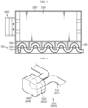
- FIG. 4 is a perspective view of a cooling block in a battery module according to a first embodiment of the present disclosure.
- the battery module 10 includes a battery cell 100, a case 200, a cover 300, a cooling block 400, and a cooling pipe 500.
- the battery cell 100 may be various.
- the battery cell 100 may be provided as a pouch-type battery cell 100 or as a cylindrical battery cell 100.
- the battery cell 100 is provided with an electrode lead, and the electrode lead provided in the battery cell 100 is a type of terminal connected to an external device and may be made of a conductive material.
- the electrode lead may include a positive electrode lead and a negative electrode lead.
- the positive electrode lead and the negative electrode lead may be disposed in opposite directions with respect to the length direction of the battery cell 100, or the positive electrode lead and the negative electrode lead may be located in the same direction with respect to the length direction of the battery cell 100.
- the positive electrode lead and the negative electrode lead may be made of various materials, and for example, the positive electrode lead may be made of an aluminum material and the negative electrode lead may be made of a copper material.
- the electrode lead may be electrically coupled to the bus bar.
- the battery cell 100 may have a structure in which a unit cell arranged in the order of positive electrode plate-separator-negative electrode plate or a bi-cell arranged in the order of positive electrode plate-separator-negative electrode plate-separator-positive electrode plate-separator-negative electrode plate are stacked in plurality according to battery capacity.
- the plurality of battery cells 100 may be accommodated inside the case 200 in various ways, for example, the plurality of battery cells 100 may be stacked on each other and accommodated in the form of a battery cell stack.
- the battery cell 100 may have various structures, and the plurality of battery cells 100 may be stacked in various methods.
- the battery cell stack may include a plurality of cartridges (not shown) accommodating each battery cell 100.
- Each cartridge (not shown) may be manufactured by plastic injection molding, and a plurality of cartridges (not shown) formed with an accommodation portion capable of accommodating the battery cell 100 may be stacked.
- a cartridge assembly in which a plurality of cartridges (not shown) are stacked may include a connector element or a terminal element.
- the connector element may include, for example, various types of electrical connection components or connection members for being connected to a battery management system (BMS, not shown) capable of providing data on the voltage or temperature of the battery cell 100.
- BMS battery management system
- the terminal element includes a positive electrode terminal and a negative electrode terminal as a main terminal connected to the battery cell 100.
- the case 200 accommodates a plurality of battery cells 100, for example, a battery cell stack or a cartridge assembly in which the battery cell stack is accommodated.
- the case 200 may be provided in various ways, and may include, for example, an upper case 210 and a lower case 230 as shown in FIG. 2 . However, this is only one embodiment, and the case 200 may be provided in more various ways.
- the case 200 may be provided to surround a battery cell stack or a cartridge assembly in which the battery cell stack is accommodated. That is, the case 200 surrounds the entire battery cell 100, thereby protecting the battery cell 100 from external vibration or impact.
- the case 200 may be formed in a shape corresponding to the shape of the battery cell 100, for example, a battery cell stack or a cartridge assembly.
- the case 200 may also be provided in a hexahedral shape to correspond thereto.
- the cover 300 is coupled to the case 200. Referring to FIGS. 1 and 2 , the cover 300 may be coupled to the lower side of the case 200. However, the coupling portion of the cover 300 may be various.
- At least one block coupling groove 310 to which the cooling block 400 is coupled may be formed in the cover 300.
- the block coupling groove 310 may be formed in various ways.
- the block coupling groove 310 may be formed by the first partition wall 311 and the second partition wall 312.
- first partition wall 311 may protrude upward in the horizontal direction from the bottom of the cover 300.
- second partition wall 312 may protrude upward in the vertical direction so as to intersect with the first partition wall 311. That is, the first partition wall 311 in the horizontal direction and the second partition wall 312 in the vertical direction may intersect to form the block coupling groove 310.
- first partition wall 311 and the second partition wall 312 are configured to be orthogonal to each other, but are not limited thereto.
- first partition wall 311 and the second partition wall 312 may be provided in plurality, and the plurality of first partition walls 311 and the plurality of second partition walls 312 may intersect to form a plurality of block coupling grooves 310.
- one or more cooling blocks 400 may be provided and coupled to at least one of the plurality of block coupling grooves 310.
- the cooling block 400 may be disposed in any block coupling groove 310 among the plurality of block coupling grooves 310, and thus the cooling block 400 may be installed to correspond to the arrangement shape of the battery cells 100 stacked in the case 200, whereby there is an effect of sufficiently cooling the battery cells 100 arranged in various ways.
- the block coupling groove 310 may be formed to be inserted downward from the bottom of the cover 300.
- the cooling block 400 is composed of one or more, and may be variously coupled to any block coupling groove 310 among the plurality of block coupling grooves 310 formed in the cover 300. Also, the cooling block 400 is in contact with the case 200 while being coupled to the block coupling groove 310 to cool the battery cell 100.
- the cooling pipe 500 is coupled to the cooling block 400 and air or water flows through the cooling pipe 500, and thus when the cooling block 400 is in contact with the case 200, heat may be transferred to the battery cell 100 accommodated in the case 200.
- the cooling block 400 may be disposed in any block coupling groove 310 among the plurality of block coupling grooves 310 formed in the cover 300, the coupling position in the cover 300 is variable. That is, the cooling block 400 may be variably configured in various ways to correspond to the arrangement position or stacking shape of the battery cells 100.
- the cooling block 400 may be configured to be inserted into the block coupling groove 310, and the shape of the cooling block 400 may be formed to correspond to the shape of the block coupling groove 310.
- the cooling block 400 may have a hexahedral shape, but the shape of the cooling block 400 is not limited thereto.
- the cooling block 400 may transfer cold air from the fluid flowing through the cooling pipe 500 to the battery cell 100, thereby cooling the battery cell 100.
- the cooling block 400 may be made of a plastic-based injection molding material or aluminum.
- cooling block 400 When the cooling block 400 is made of a plastic-based injection molding material, a second pipe to be described later may be located inside the cooling block 400.
- a pipe-shaped connection groove may be formed inside the cooling block 400.
- the cooling pipe 500 is coupled to the cooling block 400, and a fluid such as water or air moves through the inside of the cooling pipe 500.
- a fluid such as water or air cools the battery cell 100 through the cooling block 400 and the case 200 while moving through the cooling pipe 500.
- the fluid for cooling the battery cell 100 is not limited to water or air.
- the cooling pipe 500 may include a first pipe portion 510 and a second pipe portion 520.
- the first pipe portion 510 is located outside the cooling block 400.
- the second pipe portion 520 extends from the first pipe portion and is located inside the cooling block 400.
- the second pipe portion 520 may be formed in a shape close to "U", but the shape of the second pipe portion 520 is not limited thereto.
- the cooling pipe 500 may be configured to connect all of the plurality of cooling blocks 400.
- the electrical cooling pipe 650 for cooling the electrical member 600 is shown in the case of FIG. 8 corresponding to the second embodiment, the cooling pipe 500 of the first embodiment for cooling the battery cell 100 is also common thereto, and thus FIG. 8 may also be referred to for the cooling pipe 500 of the first embodiment.
- the cooling pipe 500 may be made of various materials, for example, silicon or rubber. However, the material of the cooling pipe 500 is not limited thereto.
- a case 200 in which a plurality of battery cells 100 are accommodated is coupled to a cover 300, and block coupling grooves 310 are formed in the cover 300 so that one or more cooling blocks 400 may be coupled to any position of the plurality of block coupling grooves 310.
- the cooling pipe 500 is coupled to the cooling block 400 so that a fluid for cooling flows through the cooling pipe 500.
- the cooling block 400 is in contact with the case 200 and cools the plurality of battery cells 100 accommodated in the case 200.
- the plurality of battery cells 100 may be disposed or stacked in the case 200 in various methods, and when the arrangement of the plurality of battery cells 100 is changed, the position of the cooling block 400 coupled to the block coupling groove 310 may be changed, whereby there is an effect of efficiently cooling the battery cell 100 having a changed arrangement.
- FIG. 5 is an exploded perspective view of an electrical member included in a battery module according to a second embodiment of the present disclosure
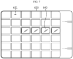
- FIGS. 6 and 7 are plan views of cooling blocks variously disposed in an electrical member of a battery module according to a second embodiment of the present disclosure
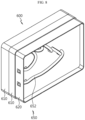
- FIG. 8 is a perspective view showing a lower surface of an electrical member provided in a battery module according to a second embodiment of the present disclosure.
- an electrical member 600 refers to a member provided with electrical components 630 related to electricity, such as a relay and a bus bar, and heat is generated by electricity. Therefore, the electrical member 600 also needs to be cooled.
- a description of the plurality of battery cells 100 and the case 200 in which the plurality of battery cells 100 are accommodated is replaced with the description of the first embodiment described above.
- the structure for cooling the battery cell 100 in the second embodiment may be the same as that of the first embodiment described above, or may be provided to cool the battery cell 100 in a different method.
- the electrical member 600 is coupled to various portions of the case 200.
- the electrical member 600 may be coupled to the outer side surface of the case 200 as shown in FIG. 1 .
- the electrical member 600 may be coupled to the inside of the case 200, although not shown in the drawings.
- the electrical member 600 may be configured to include an electrical case 610 and an electrical cover 620.
- Various electrical components 630 are accommodated in the electrical case 610, thereby protecting the electrical components 630 from external impact.
- the electrical cover 620 is coupled to the electrical case 610.
- At least one electrical block coupling groove 621 to which the electrical cooling block 640 is coupled is formed in the electrical cover 620.
- the electrical cooling block 640 of the second embodiment has a difference in the cooling target from the cooling block 400 of the first embodiment for cooling the battery cell 100 in that it cools the electrical component 630, but since the basic configuration of the electrical cover 620, the electrical cooling block 640, and the electrical block coupling groove 621 is common to that of the cover 300, the cooling block 400, and the block coupling groove 310 described in the first embodiment, the description thereof is replaced with the above-described description.
- the cooling block 400 is coupled to the block coupling groove 310 at various locations according to various arrangements of the plurality of battery cells 100 in the first embodiment, so may the electric cooling block 640 be coupled to the block coupling groove 310 at various locations according to the arrangement form of the electrical component 630 provided in the electrical member 600 in the second embodiment.
- the electrical cooling block 640 is coupled to any electrical block coupling groove 621 among the plurality of electrical block coupling grooves 621, whereby the arrangement of the electrical cooling block 640 may be modified in various ways.
- cooling block 400 cools the plurality of battery cells 100 in the first embodiment
- the electrical cooling block 640 cools the electrical component 630 provided in the electrical member 600 in the second embodiment, that is, a difference in the object of cooling, but the other basic configuration is common.
- the electrical cooling block 640 is disposed on the electrical cover 620 of the electrical member 600 to cool the electrical component 630 and is configured to have a variable coupling position in the electrical cover 620.
- the electrical cooling pipe 650 is coupled to the electrical cooling block 640.
- the electrical cooling pipe 650 includes a first pipe portion 651 located outside the electrical cooling block 640, and a second pipe portion 652 extending from the first pipe portion and located inside the electrical cooling block 640. Since the second pipe portion 652 is in common with the cooling pipe 500 of the first embodiment in that it is formed in a shape close to "U", a description thereof is replaced with the above-described description with reference to FIG. 4 .
- the electrical component 630 in the electrical member 600 may be disposed in the electrical case 610 in various ways in the case of the second embodiment, but when the arrangement of the electrical component 630 is changed, the position of the electrical cooling block 640 coupled to the electrical block coupling groove 621 may also be changed, whereby there is an effect of efficiently cooling the electrical component 630 having a changed arrangement.
- a battery pack (not shown) according to an embodiment of the present disclosure may include one or more battery modules 10 according to an embodiment of the present disclosure as described above. Also, the battery pack (not shown) may further include, in addition to the battery module 10, a housing for accommodating the battery module 10 and various devices for controlling charge/discharge of the battery module 10, such as a BMS, a current sensor, a fuse, and the like.
- a vehicle (not shown) may include the battery module 10 or the battery pack (not shown) as described above, and the battery module 10 may be included in the battery pack (not shown).
- the battery module 10 according to an embodiment of the present disclosure may be applied to the vehicle (not shown), for example, a predetermined vehicle (not shown) provided to use electricity such as an electric vehicle or a hybrid vehicle.
- the present disclosure relates to a battery module, and a battery pack and a vehicle including the same, and is particularly applicable to industries related to secondary batteries.
Landscapes
- Chemical & Material Sciences (AREA)
- Chemical Kinetics & Catalysis (AREA)
- Electrochemistry (AREA)
- General Chemical & Material Sciences (AREA)
- Engineering & Computer Science (AREA)
- Manufacturing & Machinery (AREA)
- Aviation & Aerospace Engineering (AREA)
- Secondary Cells (AREA)
- Battery Mounting, Suspending (AREA)
- Cooling, Air Intake And Gas Exhaust, And Fuel Tank Arrangements In Propulsion Units (AREA)
Abstract
Description
- The present application claims priority to
Korean Patent Application No. 10-2022-0001137 filed on January 4, 2022 - The present disclosure relates to a battery module, and a battery pack and a vehicle including the same, and more specifically, to a battery module having a variably disposed cooling block, and a battery pack and a vehicle including the same.
- As the technology development and demand for mobile devices increase, demand for secondary batteries as an energy source is rapidly increasing, and nickel cadmium batteries or hydrogen ion batteries have been used as conventional secondary batteries, but recently, lithium secondary batteries that have almost no memory effect compared to nickel-based secondary batteries and thus have advantages of free charge/discharge, very low self-discharge rate, and high energy density, are widely used.
- These lithium secondary batteries mainly use a lithium-based oxide and a carbon material as a positive electrode active material and a negative electrode active material, respectively. A lithium secondary battery includes an electrode assembly in which a positive electrode plate and a negative electrode plate coated with the positive electrode active material and the negative electrode active material, respectively, are disposed with a separator therebetween, and an exterior material that seals and accommodates the electrode assembly together with an electrolyte, that is, a battery case.
- A lithium secondary battery is composed of a positive electrode, a negative electrode, a separator interposed therebetween and an electrolyte, and is classified into a lithium-ion battery (LIB), a polymer lithium-ion battery (PLIB), and the like depending on which a positive electrode active material and a negative electrode active material are used. Typically, electrodes of these lithium secondary batteries are formed by coating a positive electrode or negative electrode active material on a current collector, such as an aluminum or copper sheet, mesh, film, foil, or the like, and then drying the same. In addition, various types of secondary batteries are provided with a case capable of protecting battery cells, and include a battery module in which a plurality of battery cells are stacked and inserted into the case, and a battery pack including a plurality of battery modules.
- Meanwhile, a cooling pipe through which water or air moves may be installed in the battery module to cool the battery cell. Here, the battery cell may be stacked or accommodated in a case in various ways, but the cooling pipe for cooling is fixed although there is a difference in the portion where heat is generated depending on the stacking or accommodating method of the battery cells, and thus there is a problem of being difficult to cope with this.
- In addition, the battery module may include electrical components related to electricity, and in the case of electrical components in the prior art, a cooling device is not provided or cooling is simply performed using a cooling fan although heat is generated, whereby there is a problem in that cooling efficiency is low.
- The present disclosure is designed to solve the problems of the related art, and therefore the present disclosure is directed to providing a battery module capable of cooling battery cells or electrical components even when the arrangement position of the battery cells or electrical components is changed, and a battery pack and a vehicle including the same.
- According to one aspect of the present disclosure, there may be provided a battery module including a plurality of battery cells; a case in which the plurality of battery cells are accommodated; a cover coupled to the case; at least one cooling block coupled to the cover and in contact with the case to cool the battery cell; and a cooling pipe coupled to the cooling block, wherein the cooling block has a variable coupling position in the cover.
- In one aspect, at least one block coupling groove to which the cooling block is coupled may be formed in the cover.
- Preferably, the block coupling groove may be formed by a first partition wall protruding upward in the horizontal direction from the bottom of the cover and a second partition wall protruding upward in the vertical direction so as to intersect with the first partition wall.
- Preferably, the first partition wall and the second partition wall may be configured to be orthogonal to each other.
- Preferably, the first partition wall and the second partition wall may be provided in plurality, a plurality of first partition walls and a plurality of second partition walls may intersect to form a plurality of block coupling grooves, and the cooling block may be coupled to at least one of the plurality of block coupling grooves.
- In another aspect, the cooling pipe may include a first pipe portion located outside the cooling block; and a second pipe portion extending from the first pipe portion and located inside the cooling block.
- Preferably, the second pipe portion may be formed in a shape close to "U".
- Meanwhile, according to another aspect of the present disclosure, there may be provided a battery module including a plurality of battery cells; a case in which the plurality of battery cells are accommodated; an electrical member coupled to the case; an electrical cooling block disposed on the electrical member so as to cool an electrical component; and an electrical cooling pipe coupled to the electrical cooling block, wherein the electrical cooling block has a variable coupling position in the electrical member.
- In one aspect, the electrical member may include an electrical case in which the electrical component is accommodated; and an electrical cover coupled to the electrical case, wherein at least one electrical block coupling groove to which the electrical cooling block is coupled may be formed in the electrical cover.
- In another aspect, the electrical cooling pipe may include a first pipe portion located outside the electrical cooling block; and a second pipe portion extending from the first pipe portion and located inside the electrical cooling block.
- Preferably, the second pipe portion may be formed in a shape close to "U".
- Meanwhile, according to still another aspect of the present disclosure, there may be provided a battery pack including the above-described battery module, and there may also be provided a vehicle including the above-described battery module.
- According to embodiments of the present disclosure, the cooling block is variably configured, and thus there is an effect of cooling battery cells or electrical components even when the arrangement position of the battery cells or electrical components is changed.
-
-
FIG. 1 is an overall perspective view of a battery module according to a first embodiment of the present disclosure. -
FIG. 2 is an exploded perspective view ofFIG. 1 . -
FIG. 3 is a cross-sectional view taken along line A-A' ofFIG. 1 . -
FIG. 4 is a perspective view of a cooling block in a battery module according to a first embodiment of the present disclosure. -
FIG. 5 is an exploded perspective view of an electrical member included in a battery module according to a second embodiment of the present disclosure. -
FIGS. 6 and7 are plan views of cooling blocks variously disposed in an electrical member of a battery module according to a second embodiment of the present disclosure. -
FIG. 8 is a perspective view showing a lower surface of an electrical member provided in a battery module according to a second embodiment of the present disclosure. - Hereinafter, preferred embodiments of the present disclosure will be described in detail with reference to the accompanying drawings. It should be understood that the terms used in the specification and the appended claims should not be construed as limited to general and dictionary meanings, but interpreted based on the meanings and concepts corresponding to technical aspects of the present disclosure on the basis of the principle that the inventor is allowed to define terms appropriately for the best explanation. Therefore, the description proposed herein is just a preferable example for the purpose of illustrations only, not intended to limit the scope of the disclosure, so it should be understood that other equivalents and modifications could be made thereto without departing from the scope of the disclosure.
- In the drawings, the size of each component or a specific portion constituting the component is exaggerated, omitted, or schematically illustrated for convenience and clarity of description. Therefore, the size of each component does not fully reflect the actual size. If it is determined that a detailed description of a related known function or configuration may unnecessarily obscure the gist of the present disclosure, such a description will be omitted.
- As used herein, the term 'coupling' or 'connection' refers to not only a case where one member and another member are directly coupled or directly connected, but also a case where one member is indirectly coupled or indirectly connected to another member through a joint member.
-
FIG. 1 is an overall perspective view of a battery module according to a first embodiment of the present disclosure,FIG. 2 is an exploded perspective view ofFIG. 1 ,FIG. 3 is a cross-sectional view taken along line A-A' ofFIG. 1 , andFIG. 4 is a perspective view of a cooling block in a battery module according to a first embodiment of the present disclosure. - Referring to the drawings, the
battery module 10 according to the first embodiment of the present disclosure includes abattery cell 100, acase 200, acover 300, acooling block 400, and acooling pipe 500. - Referring to
FIGS. 1 and2 , a plurality ofbattery cells 100 are accommodated and protected inside thecase 200. Here, thebattery cell 100 may be various. For example, thebattery cell 100 may be provided as a pouch-type battery cell 100 or as acylindrical battery cell 100. - The
battery cell 100 is provided with an electrode lead, and the electrode lead provided in thebattery cell 100 is a type of terminal connected to an external device and may be made of a conductive material. - The electrode lead may include a positive electrode lead and a negative electrode lead. The positive electrode lead and the negative electrode lead may be disposed in opposite directions with respect to the length direction of the
battery cell 100, or the positive electrode lead and the negative electrode lead may be located in the same direction with respect to the length direction of thebattery cell 100. - The positive electrode lead and the negative electrode lead may be made of various materials, and for example, the positive electrode lead may be made of an aluminum material and the negative electrode lead may be made of a copper material.
- The electrode lead may be electrically coupled to the bus bar. The
battery cell 100 may have a structure in which a unit cell arranged in the order of positive electrode plate-separator-negative electrode plate or a bi-cell arranged in the order of positive electrode plate-separator-negative electrode plate-separator-positive electrode plate-separator-negative electrode plate are stacked in plurality according to battery capacity. - The plurality of
battery cells 100 may be accommodated inside thecase 200 in various ways, for example, the plurality ofbattery cells 100 may be stacked on each other and accommodated in the form of a battery cell stack. Here, thebattery cell 100 may have various structures, and the plurality ofbattery cells 100 may be stacked in various methods. - The battery cell stack may include a plurality of cartridges (not shown) accommodating each
battery cell 100. Each cartridge (not shown) may be manufactured by plastic injection molding, and a plurality of cartridges (not shown) formed with an accommodation portion capable of accommodating thebattery cell 100 may be stacked. - A cartridge assembly in which a plurality of cartridges (not shown) are stacked may include a connector element or a terminal element. The connector element may include, for example, various types of electrical connection components or connection members for being connected to a battery management system (BMS, not shown) capable of providing data on the voltage or temperature of the
battery cell 100. - Also, the terminal element includes a positive electrode terminal and a negative electrode terminal as a main terminal connected to the
battery cell 100. - Referring to
FIGS. 1 and2 , thecase 200 accommodates a plurality ofbattery cells 100, for example, a battery cell stack or a cartridge assembly in which the battery cell stack is accommodated. - The
case 200 may be provided in various ways, and may include, for example, anupper case 210 and a lower case 230 as shown inFIG. 2 . However, this is only one embodiment, and thecase 200 may be provided in more various ways. - Here, the
case 200 may be provided to surround a battery cell stack or a cartridge assembly in which the battery cell stack is accommodated. That is, thecase 200 surrounds theentire battery cell 100, thereby protecting thebattery cell 100 from external vibration or impact. - The
case 200 may be formed in a shape corresponding to the shape of thebattery cell 100, for example, a battery cell stack or a cartridge assembly. For example, when the battery cell stack or the cartridge assembly is provided in a hexahedral shape, thecase 200 may also be provided in a hexahedral shape to correspond thereto. - The
cover 300 is coupled to thecase 200. Referring toFIGS. 1 and2 , thecover 300 may be coupled to the lower side of thecase 200. However, the coupling portion of thecover 300 may be various. - At least one
block coupling groove 310 to which thecooling block 400 is coupled may be formed in thecover 300. Here, theblock coupling groove 310 may be formed in various ways. For example, theblock coupling groove 310 may be formed by thefirst partition wall 311 and thesecond partition wall 312. - Here, the
first partition wall 311 may protrude upward in the horizontal direction from the bottom of thecover 300. Also, thesecond partition wall 312 may protrude upward in the vertical direction so as to intersect with thefirst partition wall 311. That is, thefirst partition wall 311 in the horizontal direction and thesecond partition wall 312 in the vertical direction may intersect to form theblock coupling groove 310. Referring toFIG. 2 , thefirst partition wall 311 and thesecond partition wall 312 are configured to be orthogonal to each other, but are not limited thereto. - Referring to
FIG. 2 , thefirst partition wall 311 and thesecond partition wall 312 may be provided in plurality, and the plurality offirst partition walls 311 and the plurality ofsecond partition walls 312 may intersect to form a plurality ofblock coupling grooves 310. In addition, one or more cooling blocks 400 may be provided and coupled to at least one of the plurality ofblock coupling grooves 310. - As described above, the
cooling block 400 may be disposed in anyblock coupling groove 310 among the plurality ofblock coupling grooves 310, and thus thecooling block 400 may be installed to correspond to the arrangement shape of thebattery cells 100 stacked in thecase 200, whereby there is an effect of sufficiently cooling thebattery cells 100 arranged in various ways. - On the other hand, in another embodiment of the
block coupling groove 310, theblock coupling groove 310 may be formed to be inserted downward from the bottom of thecover 300. - The
cooling block 400 is composed of one or more, and may be variously coupled to anyblock coupling groove 310 among the plurality ofblock coupling grooves 310 formed in thecover 300. Also, thecooling block 400 is in contact with thecase 200 while being coupled to theblock coupling groove 310 to cool thebattery cell 100. Thecooling pipe 500 is coupled to thecooling block 400 and air or water flows through thecooling pipe 500, and thus when thecooling block 400 is in contact with thecase 200, heat may be transferred to thebattery cell 100 accommodated in thecase 200. - Since the
cooling block 400 may be disposed in anyblock coupling groove 310 among the plurality ofblock coupling grooves 310 formed in thecover 300, the coupling position in thecover 300 is variable. That is, thecooling block 400 may be variably configured in various ways to correspond to the arrangement position or stacking shape of thebattery cells 100. - The
cooling block 400 may be configured to be inserted into theblock coupling groove 310, and the shape of thecooling block 400 may be formed to correspond to the shape of theblock coupling groove 310. For example, thecooling block 400 may have a hexahedral shape, but the shape of thecooling block 400 is not limited thereto. - The
cooling block 400 may transfer cold air from the fluid flowing through thecooling pipe 500 to thebattery cell 100, thereby cooling thebattery cell 100. Thecooling block 400 may be made of a plastic-based injection molding material or aluminum. - When the
cooling block 400 is made of a plastic-based injection molding material, a second pipe to be described later may be located inside thecooling block 400. Alternatively, when thecooling block 400 is made of aluminum by, for example, die casting, a pipe-shaped connection groove may be formed inside thecooling block 400. However, this is only one embodiment. - The
cooling pipe 500 is coupled to thecooling block 400, and a fluid such as water or air moves through the inside of thecooling pipe 500. A fluid such as water or air cools thebattery cell 100 through thecooling block 400 and thecase 200 while moving through thecooling pipe 500. However, the fluid for cooling thebattery cell 100 is not limited to water or air. - Referring to
FIGS. 3 and 4 , thecooling pipe 500 may include afirst pipe portion 510 and asecond pipe portion 520. Thefirst pipe portion 510 is located outside thecooling block 400. Also, thesecond pipe portion 520 extends from the first pipe portion and is located inside thecooling block 400. As shown inFIG. 4 , thesecond pipe portion 520 may be formed in a shape close to "U", but the shape of thesecond pipe portion 520 is not limited thereto. - The
cooling pipe 500 may be configured to connect all of the plurality of cooling blocks 400. Although theelectrical cooling pipe 650 for cooling theelectrical member 600 is shown in the case ofFIG. 8 corresponding to the second embodiment, thecooling pipe 500 of the first embodiment for cooling thebattery cell 100 is also common thereto, and thusFIG. 8 may also be referred to for thecooling pipe 500 of the first embodiment. - The
cooling pipe 500 may be made of various materials, for example, silicon or rubber. However, the material of thecooling pipe 500 is not limited thereto. - Hereinafter, the operation and effect of the
battery module 10 according to the first embodiment of the present disclosure will be described with reference to the drawings. - A
case 200 in which a plurality ofbattery cells 100 are accommodated is coupled to acover 300, andblock coupling grooves 310 are formed in thecover 300 so that one or more cooling blocks 400 may be coupled to any position of the plurality ofblock coupling grooves 310. - In addition, the
cooling pipe 500 is coupled to thecooling block 400 so that a fluid for cooling flows through thecooling pipe 500. Thecooling block 400 is in contact with thecase 200 and cools the plurality ofbattery cells 100 accommodated in thecase 200. - Here, the plurality of
battery cells 100 may be disposed or stacked in thecase 200 in various methods, and when the arrangement of the plurality ofbattery cells 100 is changed, the position of thecooling block 400 coupled to theblock coupling groove 310 may be changed, whereby there is an effect of efficiently cooling thebattery cell 100 having a changed arrangement. -
FIG. 5 is an exploded perspective view of an electrical member included in a battery module according to a second embodiment of the present disclosure,FIGS. 6 and7 are plan views of cooling blocks variously disposed in an electrical member of a battery module according to a second embodiment of the present disclosure, andFIG. 8 is a perspective view showing a lower surface of an electrical member provided in a battery module according to a second embodiment of the present disclosure. - Hereinafter, cooling of the
electrical member 600 provided in thebattery module 10 will be described, but a description of portions common to the cooling method of thebattery cell 100 in the above-described first embodiment is replaced with the above-described description. - Referring to
FIG. 5 , anelectrical member 600 refers to a member provided withelectrical components 630 related to electricity, such as a relay and a bus bar, and heat is generated by electricity. Therefore, theelectrical member 600 also needs to be cooled. - A description of the plurality of
battery cells 100 and thecase 200 in which the plurality ofbattery cells 100 are accommodated is replaced with the description of the first embodiment described above. However, the structure for cooling thebattery cell 100 in the second embodiment may be the same as that of the first embodiment described above, or may be provided to cool thebattery cell 100 in a different method. - The
electrical member 600 is coupled to various portions of thecase 200. For example, theelectrical member 600 may be coupled to the outer side surface of thecase 200 as shown inFIG. 1 . In addition, theelectrical member 600 may be coupled to the inside of thecase 200, although not shown in the drawings. - The
electrical member 600 may be configured to include anelectrical case 610 and anelectrical cover 620. Variouselectrical components 630 are accommodated in theelectrical case 610, thereby protecting theelectrical components 630 from external impact. Also, theelectrical cover 620 is coupled to theelectrical case 610. At least one electricalblock coupling groove 621 to which theelectrical cooling block 640 is coupled is formed in theelectrical cover 620. - The
electrical cooling block 640 of the second embodiment has a difference in the cooling target from thecooling block 400 of the first embodiment for cooling thebattery cell 100 in that it cools theelectrical component 630, but since the basic configuration of theelectrical cover 620, theelectrical cooling block 640, and the electricalblock coupling groove 621 is common to that of thecover 300, thecooling block 400, and theblock coupling groove 310 described in the first embodiment, the description thereof is replaced with the above-described description. - However, as the
cooling block 400 is coupled to theblock coupling groove 310 at various locations according to various arrangements of the plurality ofbattery cells 100 in the first embodiment, so may theelectric cooling block 640 be coupled to theblock coupling groove 310 at various locations according to the arrangement form of theelectrical component 630 provided in theelectrical member 600 in the second embodiment. For example, as shown inFIGS. 6 and7 , theelectrical cooling block 640 is coupled to any electricalblock coupling groove 621 among the plurality of electricalblock coupling grooves 621, whereby the arrangement of theelectrical cooling block 640 may be modified in various ways. - That is, there is a difference in that the
cooling block 400 cools the plurality ofbattery cells 100 in the first embodiment, and theelectrical cooling block 640 cools theelectrical component 630 provided in theelectrical member 600 in the second embodiment, that is, a difference in the object of cooling, but the other basic configuration is common. - Here, the
electrical cooling block 640 is disposed on theelectrical cover 620 of theelectrical member 600 to cool theelectrical component 630 and is configured to have a variable coupling position in theelectrical cover 620. - The
electrical cooling pipe 650 is coupled to theelectrical cooling block 640. Referring toFIGS. 4 to 8 , theelectrical cooling pipe 650 includes afirst pipe portion 651 located outside theelectrical cooling block 640, and asecond pipe portion 652 extending from the first pipe portion and located inside theelectrical cooling block 640. Since thesecond pipe portion 652 is in common with thecooling pipe 500 of the first embodiment in that it is formed in a shape close to "U", a description thereof is replaced with the above-described description with reference toFIG. 4 . - That is, the
electrical component 630 in theelectrical member 600 may be disposed in theelectrical case 610 in various ways in the case of the second embodiment, but when the arrangement of theelectrical component 630 is changed, the position of theelectrical cooling block 640 coupled to the electricalblock coupling groove 621 may also be changed, whereby there is an effect of efficiently cooling theelectrical component 630 having a changed arrangement. - Meanwhile, a battery pack (not shown) according to an embodiment of the present disclosure may include one or
more battery modules 10 according to an embodiment of the present disclosure as described above. Also, the battery pack (not shown) may further include, in addition to thebattery module 10, a housing for accommodating thebattery module 10 and various devices for controlling charge/discharge of thebattery module 10, such as a BMS, a current sensor, a fuse, and the like. - Meanwhile, a vehicle (not shown) according to an embodiment of the present disclosure may include the
battery module 10 or the battery pack (not shown) as described above, and thebattery module 10 may be included in the battery pack (not shown). In addition, thebattery module 10 according to an embodiment of the present disclosure may be applied to the vehicle (not shown), for example, a predetermined vehicle (not shown) provided to use electricity such as an electric vehicle or a hybrid vehicle. - While the present disclosure has been hereinabove described with regard to a limited number of embodiments and drawings, the present disclosure is not limited thereto and it is obvious to those skilled in the art that a variety of modifications and changes may be made thereto within the technical aspects of the present disclosure and the equivalent scope of the appended claims.
- The present disclosure relates to a battery module, and a battery pack and a vehicle including the same, and is particularly applicable to industries related to secondary batteries.
Claims (13)
- A battery module comprising:a plurality of battery cells;a case in which the plurality of battery cells are accommodated;a cover coupled to the case;at least one cooling block coupled to the cover and in contact with the case to cool the battery cell; anda cooling pipe coupled to the cooling block,wherein the cooling block has a variable coupling position in the cover.
- The battery module according to claim 1,
wherein at least one block coupling groove to which the cooling block is coupled is formed in the cover. - The battery module according to claim 2,
wherein the block coupling groove is formed by a first partition wall protruding upward in the horizontal direction from the bottom of the cover and a second partition wall protruding upward in the vertical direction so as to intersect with the first partition wall. - The battery module according to claim 3,
wherein the first partition wall and the second partition wall are configured to be orthogonal to each other. - The battery module according to claim 4,wherein the first partition wall and the second partition wall are provided in plurality,a plurality of first partition walls and a plurality of second partition walls intersect to form a plurality of block coupling grooves, andthe cooling block is coupled to at least one of the plurality of block coupling grooves.
- The battery module according to claim 1,
wherein the cooling pipe comprises:a first pipe portion located outside the cooling block; anda second pipe portion extending from the first pipe portion and located inside the cooling block. - The battery module according to claim 6,
wherein the second pipe portion is formed in a shape close to "U". - A battery module comprising:a plurality of battery cells;a case in which the plurality of battery cells are accommodated;an electrical member coupled to the case;an electrical cooling block disposed on the electrical member so as to cool an electrical component; andan electrical cooling pipe coupled to the electrical cooling block,wherein the electrical cooling block has a variable coupling position in the electrical member.
- The battery module according to claim 8,
wherein the electrical member comprises:an electrical case in which the electrical component is accommodated; andan electrical cover coupled to the electrical case,wherein at least one electrical block coupling groove to which the electrical cooling block is coupled is formed in the electrical cover. - The battery module according to claim 8,
wherein the electrical cooling pipe comprises:a first pipe portion located outside the electrical cooling block; anda second pipe portion extending from the first pipe portion and located inside the electrical cooling block. - The battery module according to claim 10,
wherein the second pipe portion is formed in a shape close to "U". - A battery pack comprising a battery module according to any one of claims 1 to 11.
- A vehicle comprising a battery module according to any one of claims 1 to 11.
Applications Claiming Priority (2)
| Application Number | Priority Date | Filing Date | Title |
|---|---|---|---|
| KR1020220001137A KR102957152B1 (en) | 2022-01-04 | Battery module and battery pack including the same and vehicle including the same | |
| PCT/KR2022/020892 WO2023132527A1 (en) | 2022-01-04 | 2022-12-20 | Battery module, and battery pack and vehicle comprising same |
Publications (2)
| Publication Number | Publication Date |
|---|---|
| EP4379909A1 true EP4379909A1 (en) | 2024-06-05 |
| EP4379909A4 EP4379909A4 (en) | 2024-12-18 |
Family
ID=87073792
Family Applications (1)
| Application Number | Title | Priority Date | Filing Date |
|---|---|---|---|
| EP22919064.0A Pending EP4379909A4 (en) | 2022-01-04 | 2022-12-20 | Battery module, and battery pack and vehicle comprising same |
Country Status (5)
| Country | Link |
|---|---|
| US (1) | US20250253432A1 (en) |
| EP (1) | EP4379909A4 (en) |
| JP (1) | JP7711300B2 (en) |
| CN (1) | CN117480671A (en) |
| WO (1) | WO2023132527A1 (en) |
Family Cites Families (16)
| Publication number | Priority date | Publication date | Assignee | Title |
|---|---|---|---|---|
| JP2009043869A (en) * | 2007-08-08 | 2009-02-26 | Nissan Diesel Motor Co Ltd | Capacitor device |
| JP5183175B2 (en) * | 2007-11-29 | 2013-04-17 | 三洋電機株式会社 | Battery system |
| KR101021114B1 (en) * | 2008-11-14 | 2011-03-14 | 현대자동차일본기술연구소 | Vehicle Battery Cooling System |
| KR101281036B1 (en) * | 2010-12-06 | 2013-07-09 | 주식회사 엘지화학 | Secondary battery cooling apparatus with enhanced cooling efficiency and secondary battery system having the same |
| EP3291358A1 (en) * | 2016-08-31 | 2018-03-07 | Akasol GmbH | Battery module assembly and cooling plate for use in a battery module assembly |
| KR102391118B1 (en) * | 2017-06-07 | 2022-04-27 | 삼성에스디아이 주식회사 | Battery pack |
| JP7223948B2 (en) * | 2017-08-24 | 2023-02-17 | パナソニックIpマネジメント株式会社 | battery pack |
| KR20190036379A (en) * | 2017-09-27 | 2019-04-04 | 엠에이치기술개발 주식회사 | Cooling plate |
| CN108306072B (en) * | 2018-01-04 | 2020-02-07 | 福建省汽车工业集团云度新能源汽车股份有限公司 | Parallel heat exchange battery pack |
| CN110635193B (en) * | 2018-06-22 | 2024-02-27 | 陕西汽车集团股份有限公司 | Manufacturing method of liquid cooling plate structure with freely-built cooling flow channel |
| JP7209219B2 (en) * | 2019-03-30 | 2023-01-20 | パナソニックIpマネジメント株式会社 | Cooling device and enclosure |
| JP7209220B2 (en) * | 2019-03-30 | 2023-01-20 | パナソニックIpマネジメント株式会社 | Cooling device and enclosure |
| JP2021197210A (en) * | 2020-06-09 | 2021-12-27 | 旭化成株式会社 | Composite article |
| KR102789969B1 (en) | 2020-06-29 | 2025-04-03 | 에스케이하이닉스 주식회사 | Memory system, memory device, and operating method of memory device |
| CN212209704U (en) * | 2020-06-30 | 2020-12-22 | 蜂巢能源科技有限公司 | Cooling plate assemblies and vehicles |
| CN214898571U (en) * | 2021-01-14 | 2021-11-26 | 恒大新能源技术(深圳)有限公司 | Power battery pack and cooling mechanism thereof |
-
2022
- 2022-12-20 CN CN202280041167.5A patent/CN117480671A/en active Pending
- 2022-12-20 WO PCT/KR2022/020892 patent/WO2023132527A1/en not_active Ceased
- 2022-12-20 EP EP22919064.0A patent/EP4379909A4/en active Pending
- 2022-12-20 JP JP2024501203A patent/JP7711300B2/en active Active
- 2022-12-20 US US18/291,293 patent/US20250253432A1/en active Pending
Also Published As
| Publication number | Publication date |
|---|---|
| JP2024528600A (en) | 2024-07-30 |
| EP4379909A4 (en) | 2024-12-18 |
| US20250253432A1 (en) | 2025-08-07 |
| JP7711300B2 (en) | 2025-07-22 |
| KR20230105574A (en) | 2023-07-11 |
| CN117480671A (en) | 2024-01-30 |
| WO2023132527A1 (en) | 2023-07-13 |
Similar Documents
| Publication | Publication Date | Title |
|---|---|---|
| EP4184667B1 (en) | Battery module, and battery pack and vehicle comprising same | |
| KR20190001410A (en) | Battery Module | |
| US10957955B2 (en) | Battery module and battery pack including the same | |
| EP4152503B1 (en) | Battery pack and vehicle comprising same | |
| EP3934009B1 (en) | Battery module and battery pack including same | |
| EP4181275A1 (en) | Battery module and battery pack including same | |
| WO2023155208A1 (en) | Battery, electric device, and method and device for preparing battery | |
| US12021212B2 (en) | Battery module, and battery pack and vehicle comprising same | |
| US20230420770A1 (en) | Battery Module, and Battery Pack and Vehicle Including the Same | |
| TW202220265A (en) | Secondary battery module, and secondary battery pack and vehicle including the same | |
| EP4379909A1 (en) | Battery module, and battery pack and vehicle comprising same | |
| CN109923730B (en) | Battery module and battery pack including the same | |
| KR102951182B1 (en) | Battery, electric device, battery manufacturing method and device | |
| KR102957152B1 (en) | Battery module and battery pack including the same and vehicle including the same | |
| JP2023511215A (en) | Battery modules, battery packs containing same and automobiles | |
| KR20220100424A (en) | Battery module and battery pack including the same and vehicle including the same | |
| CN216958271U (en) | Battery module, battery pack including same and vehicle | |
| JP7460773B2 (en) | Battery module, battery pack including same, and automobile | |
| EP4283775A1 (en) | Battery pack and vehicle including same | |
| KR20250075165A (en) | Battery module and Battery pack including of the same | |
| KR20160053694A (en) | Battery module and battery pack including the same |
Legal Events
| Date | Code | Title | Description |
|---|---|---|---|
| STAA | Information on the status of an ep patent application or granted ep patent |
Free format text: STATUS: THE INTERNATIONAL PUBLICATION HAS BEEN MADE |
|
| PUAI | Public reference made under article 153(3) epc to a published international application that has entered the european phase |
Free format text: ORIGINAL CODE: 0009012 |
|
| STAA | Information on the status of an ep patent application or granted ep patent |
Free format text: STATUS: REQUEST FOR EXAMINATION WAS MADE |
|
| 17P | Request for examination filed |
Effective date: 20240227 |
|
| AK | Designated contracting states |
Kind code of ref document: A1 Designated state(s): AL AT BE BG CH CY CZ DE DK EE ES FI FR GB GR HR HU IE IS IT LI LT LU LV MC ME MK MT NL NO PL PT RO RS SE SI SK SM TR |
|
| A4 | Supplementary search report drawn up and despatched |
Effective date: 20241119 |
|
| RIC1 | Information provided on ipc code assigned before grant |
Ipc: H01M 50/249 20210101ALI20241113BHEP Ipc: H01M 10/613 20140101ALI20241113BHEP Ipc: H01M 50/244 20210101ALI20241113BHEP Ipc: H01M 50/202 20210101ALI20241113BHEP Ipc: H01M 10/6556 20140101AFI20241113BHEP |
|
| DAV | Request for validation of the european patent (deleted) | ||
| DAX | Request for extension of the european patent (deleted) |