EP4379901A1 - Power supply for battery pack - Google Patents
Power supply for battery pack Download PDFInfo
- Publication number
- EP4379901A1 EP4379901A1 EP23197936.0A EP23197936A EP4379901A1 EP 4379901 A1 EP4379901 A1 EP 4379901A1 EP 23197936 A EP23197936 A EP 23197936A EP 4379901 A1 EP4379901 A1 EP 4379901A1
- Authority
- EP
- European Patent Office
- Prior art keywords
- battery
- voltage
- converter
- switch
- coil
- Prior art date
- Legal status (The legal status is an assumption and is not a legal conclusion. Google has not performed a legal analysis and makes no representation as to the accuracy of the status listed.)
- Granted
Links
Images



Classifications
-
- H—ELECTRICITY
- H02—GENERATION; CONVERSION OR DISTRIBUTION OF ELECTRIC POWER
- H02J—ELECTRIC POWER NETWORKS; CIRCUIT ARRANGEMENTS OR SYSTEMS FOR SUPPLYING OR DISTRIBUTING ELECTRIC POWER; SYSTEMS FOR STORING ELECTRIC ENERGY
- H02J7/00—Circuit arrangements for charging or discharging batteries or for supplying loads from batteries
-
- H—ELECTRICITY
- H02—GENERATION; CONVERSION OR DISTRIBUTION OF ELECTRIC POWER
- H02J—ELECTRIC POWER NETWORKS; CIRCUIT ARRANGEMENTS OR SYSTEMS FOR SUPPLYING OR DISTRIBUTING ELECTRIC POWER; SYSTEMS FOR STORING ELECTRIC ENERGY
- H02J7/00—Circuit arrangements for charging or discharging batteries or for supplying loads from batteries
- H02J7/34—Parallel operation in networks using both storage and other DC sources, e.g. providing buffering
-
- H—ELECTRICITY
- H02—GENERATION; CONVERSION OR DISTRIBUTION OF ELECTRIC POWER
- H02J—ELECTRIC POWER NETWORKS; CIRCUIT ARRANGEMENTS OR SYSTEMS FOR SUPPLYING OR DISTRIBUTING ELECTRIC POWER; SYSTEMS FOR STORING ELECTRIC ENERGY
- H02J7/00—Circuit arrangements for charging or discharging batteries or for supplying loads from batteries
- H02J7/855—Circuit arrangements for charging or discharging batteries or for supplying loads from batteries with circuits adapted for supplying loads from the battery
-
- H—ELECTRICITY
- H01—ELECTRIC ELEMENTS
- H01M—PROCESSES OR MEANS, e.g. BATTERIES, FOR THE DIRECT CONVERSION OF CHEMICAL ENERGY INTO ELECTRICAL ENERGY
- H01M10/00—Secondary cells; Manufacture thereof
- H01M10/42—Methods or arrangements for servicing or maintenance of secondary cells or secondary half-cells
- H01M10/425—Structural combination with electronic components, e.g. electronic circuits integrated to the outside of the casing
-
- H—ELECTRICITY
- H01—ELECTRIC ELEMENTS
- H01M—PROCESSES OR MEANS, e.g. BATTERIES, FOR THE DIRECT CONVERSION OF CHEMICAL ENERGY INTO ELECTRICAL ENERGY
- H01M10/00—Secondary cells; Manufacture thereof
- H01M10/42—Methods or arrangements for servicing or maintenance of secondary cells or secondary half-cells
- H01M10/44—Methods for charging or discharging
- H01M10/441—Methods for charging or discharging for several batteries or cells simultaneously or sequentially
-
- H—ELECTRICITY
- H02—GENERATION; CONVERSION OR DISTRIBUTION OF ELECTRIC POWER
- H02J—ELECTRIC POWER NETWORKS; CIRCUIT ARRANGEMENTS OR SYSTEMS FOR SUPPLYING OR DISTRIBUTING ELECTRIC POWER; SYSTEMS FOR STORING ELECTRIC ENERGY
- H02J3/00—Circuit arrangements for AC mains or AC distribution networks
- H02J3/28—Arrangements for balancing of the load in networks by storage of energy
- H02J3/32—Arrangements for balancing of the load in networks by storage of energy using batteries or super capacitors with converting means
-
- H—ELECTRICITY
- H02—GENERATION; CONVERSION OR DISTRIBUTION OF ELECTRIC POWER
- H02J—ELECTRIC POWER NETWORKS; CIRCUIT ARRANGEMENTS OR SYSTEMS FOR SUPPLYING OR DISTRIBUTING ELECTRIC POWER; SYSTEMS FOR STORING ELECTRIC ENERGY
- H02J7/00—Circuit arrangements for charging or discharging batteries or for supplying loads from batteries
- H02J7/50—Circuit arrangements for charging or discharging batteries or for supplying loads from batteries acting upon multiple batteries simultaneously or sequentially
-
- H—ELECTRICITY
- H02—GENERATION; CONVERSION OR DISTRIBUTION OF ELECTRIC POWER
- H02J—ELECTRIC POWER NETWORKS; CIRCUIT ARRANGEMENTS OR SYSTEMS FOR SUPPLYING OR DISTRIBUTING ELECTRIC POWER; SYSTEMS FOR STORING ELECTRIC ENERGY
- H02J7/00—Circuit arrangements for charging or discharging batteries or for supplying loads from batteries
- H02J7/60—Circuit arrangements for charging or discharging batteries or for supplying loads from batteries including safety or protection arrangements
- H02J7/63—Circuit arrangements for charging or discharging batteries or for supplying loads from batteries including safety or protection arrangements against overdischarge
-
- H—ELECTRICITY
- H02—GENERATION; CONVERSION OR DISTRIBUTION OF ELECTRIC POWER
- H02J—ELECTRIC POWER NETWORKS; CIRCUIT ARRANGEMENTS OR SYSTEMS FOR SUPPLYING OR DISTRIBUTING ELECTRIC POWER; SYSTEMS FOR STORING ELECTRIC ENERGY
- H02J7/00—Circuit arrangements for charging or discharging batteries or for supplying loads from batteries
- H02J7/60—Circuit arrangements for charging or discharging batteries or for supplying loads from batteries including safety or protection arrangements
- H02J7/663—Circuit arrangements for charging or discharging batteries or for supplying loads from batteries including safety or protection arrangements using battery or load disconnect circuits
-
- H—ELECTRICITY
- H02—GENERATION; CONVERSION OR DISTRIBUTION OF ELECTRIC POWER
- H02J—ELECTRIC POWER NETWORKS; CIRCUIT ARRANGEMENTS OR SYSTEMS FOR SUPPLYING OR DISTRIBUTING ELECTRIC POWER; SYSTEMS FOR STORING ELECTRIC ENERGY
- H02J7/00—Circuit arrangements for charging or discharging batteries or for supplying loads from batteries
- H02J7/90—Regulation of charging or discharging current or voltage
-
- H—ELECTRICITY
- H02—GENERATION; CONVERSION OR DISTRIBUTION OF ELECTRIC POWER
- H02J—ELECTRIC POWER NETWORKS; CIRCUIT ARRANGEMENTS OR SYSTEMS FOR SUPPLYING OR DISTRIBUTING ELECTRIC POWER; SYSTEMS FOR STORING ELECTRIC ENERGY
- H02J9/00—Circuit arrangements for emergency or stand-by power supply, e.g. for emergency lighting
- H02J9/005—Circuit arrangements for emergency or stand-by power supply, e.g. for emergency lighting using a power saving mode
-
- H—ELECTRICITY
- H02—GENERATION; CONVERSION OR DISTRIBUTION OF ELECTRIC POWER
- H02J—ELECTRIC POWER NETWORKS; CIRCUIT ARRANGEMENTS OR SYSTEMS FOR SUPPLYING OR DISTRIBUTING ELECTRIC POWER; SYSTEMS FOR STORING ELECTRIC ENERGY
- H02J9/00—Circuit arrangements for emergency or stand-by power supply, e.g. for emergency lighting
- H02J9/04—Circuit arrangements for emergency or stand-by power supply, e.g. for emergency lighting in which the distribution system is disconnected from the normal source and connected to a standby source
-
- H—ELECTRICITY
- H01—ELECTRIC ELEMENTS
- H01M—PROCESSES OR MEANS, e.g. BATTERIES, FOR THE DIRECT CONVERSION OF CHEMICAL ENERGY INTO ELECTRICAL ENERGY
- H01M10/00—Secondary cells; Manufacture thereof
- H01M10/42—Methods or arrangements for servicing or maintenance of secondary cells or secondary half-cells
- H01M10/425—Structural combination with electronic components, e.g. electronic circuits integrated to the outside of the casing
- H01M2010/4271—Battery management systems including electronic circuits, e.g. control of current or voltage to keep battery in healthy state, cell balancing
-
- H—ELECTRICITY
- H02—GENERATION; CONVERSION OR DISTRIBUTION OF ELECTRIC POWER
- H02J—ELECTRIC POWER NETWORKS; CIRCUIT ARRANGEMENTS OR SYSTEMS FOR SUPPLYING OR DISTRIBUTING ELECTRIC POWER; SYSTEMS FOR STORING ELECTRIC ENERGY
- H02J2207/00—Details of circuit arrangements for charging or discharging batteries or supplying loads from batteries
- H02J2207/10—Control circuit supply, e.g. means for supplying power to the control circuit
-
- H—ELECTRICITY
- H02—GENERATION; CONVERSION OR DISTRIBUTION OF ELECTRIC POWER
- H02J—ELECTRIC POWER NETWORKS; CIRCUIT ARRANGEMENTS OR SYSTEMS FOR SUPPLYING OR DISTRIBUTING ELECTRIC POWER; SYSTEMS FOR STORING ELECTRIC ENERGY
- H02J2207/00—Details of circuit arrangements for charging or discharging batteries or supplying loads from batteries
- H02J2207/20—Charging or discharging characterised by the power electronics converter
Definitions
- the present disclosure relates to a power supply of a battery pack.
- An energy storage system stores a large amount of electrical energy and supplies the stored electrical energy when it is needed to improve energy use efficiency.
- the energy storage system (ESS) includes a high-voltage battery pack for storing electrical energy, and a battery management system (BMS) for monitoring states of the battery pack and control charging and discharging of the battery pack.
- BMS battery management system
- the energy storage system uses a switched mode power supply (SMPS) to supply a control voltage (e.g., an operation voltage of the BMS) to the battery pack.
- SMPS switched mode power supply
- AC alternating current
- DC direct current
- the present disclosure attempts to provide a power supply of a battery pack for supplying an operating power voltage to a controller of the battery pack by driving a DC/DC converter while no initial power voltage is applied.
- An embodiment of the present disclosure provides a power supply including: a first battery, a second battery; a DC/DC converter for converting a first voltage output by the first battery into a second voltage; a controller for using the second voltage as an operation voltage; a relay connected between the first battery and an input terminal of the DC/DC converter and controlling an electrical connection between the first battery and the input terminal of the DC/DC converter; a first switch connected between an output terminal of the DC/DC converter and a coil of the relay and controlling an electrical connection between the output terminal of the DC/DC converter and the coil; and a second switch connected between the second battery and the coil and controlling an electrical connection between the second battery and the coil.
- Opening/closing of the first switch may be controlled by the controller, and the second switch may be a manual switch opened and closed by a physical manipulation.
- the first battery may be a high voltage battery module configuring the battery pack, and the controller may be a battery management system for controlling charging/discharging of the battery pack.
- the relay may be closed to transmit the first voltage to the DC/DC converter.
- the controller may control the first switch to be closed, and if the first switch is closed, an output voltage of the DC/DC converter may be supplied to the coil.
- the power supply may further include a first diode connected between the first switch and the coil and transmitting an output voltage of the DC/DC converter to the coil if the first switch is closed, and a second diode connected between the second switch and the coil and transmitting an output voltage of the second battery to the coil if the second switch is closed.
- the power supply may further include a third diode connected between the first switch and the second battery and transmitting an output voltage of the DC/DC converter as a charging voltage of the second battery if the first switch is closed.
- the power supply of the battery pack may be manufactured with a low cost by using the internal voltage of the battery pack and the DC/DC converter to supply the control voltage to the battery pack.
- the operating power voltage may be supplied to the controller of the battery pack by driving the DC/DC converter while no initial power voltage is input.
- the term "and/or” includes all or random combinations of a plurality of items that are related and arranged.
- the use of “may” signifies “at least one embodiment of the present invention”.
- a singular term may include a plural form unless stated in another way.
- first, second, and the like will be used only to describe various components, and are not to be interpreted as limiting these components. The terms are only used to differentiate one component from other components. For example, a first constituent element could be termed a second constituent element, and similarly, a second constituent element could be termed a first constituent element, without departing from the scope of the present invention.
- Electric connection of two constituent elements includes not only a case where the two constituent elements are directly connected, but also a case where the two constituent elements are connected through another constituent element interposed therebetween.
- Other constituent elements may include a switch, a resistor, a capacitor, and the like.
- connection means electrical connection unless there is an expression "direct connection”.
- FIG. 1 shows a power supply of a high-voltage battery pack according to an embodiment.
- the power supply 100 of the high voltage battery pack may include a controller 110, a first battery 120, a relay 140, and a DC/DC converter 150.
- the controller 110 may be a battery management system (BMS) for monitoring the high voltage battery pack and controlling charging/discharging of the high voltage battery pack.
- BMS battery management system
- the controller 110 may control a supplying of power voltage to a coil 141 of the relay 140 and may control opening/closing of the relay 140.
- the first battery 120 may be a high-voltage battery module configuring the high voltage battery pack.
- the first battery 120 may be a battery module in which a plurality of cells are connected in series or in parallel and which may provide an output voltage of about 1000V.
- the relay 140 may be connected between the first battery 120 and an input terminal of the DC/DC converter 150, and may selectively transmit an output voltage of the first battery 120 to the DC/DC converter 150.
- the relay 140 may switch contact state of nodes by a current flowing to the coil 141, may transmit an output voltage of the first battery 120 to the DC/DC converter 150 in a node contacting state, and may block the output voltage of the first battery 120 from being transmitted to the DC/DC converter 150 in a node opening state.
- the DC/DC converter 150 may, when receiving the output voltage of the first battery 120 through the relay 140, convert the output voltage into another level of voltage and may output the same.
- the DC/DC converter 150 may, when receiving the voltage of 1000V from the first battery module 110, may convert it into the voltage of 24V and may output the same.
- the voltage supplied through the output terminal of the DC/DC converter 150 may be supplied as an operation voltage of the controller 110.
- the relay 140 when the relay 140 is closed (i.e., in a node contacting state), the voltage of the first battery 120 is supplied to the DC/DC converter 150 so the DC/DC converter 150 may supply an operation voltage of the controller 110.
- power consumption may be reduced by opening the relay 140.
- the relay 140 when the relay 140 is opened, it is also blocked to supply a power voltage to the DC/DC converter 150 and the controller 110, so a method for controlling the relay 140 to be closed (i.e., a node contacting state) while the relay 140 is opened, and starting to supply the power voltage to the DC/DC converter 150 and the controller 110 is needed.
- the power supply 100 may, to solve this problem, operate the relay 140 by using the second battery 130 at its initial driving to supply the power voltage to the DC/DC converter 150 and the controller 110.
- the power supply 100 may include a second battery 130, two switches SW1 and SW2, and two diodes D1 and D2.
- the second battery 130 may be a charged/discharged battery module for supplying power in an emergency such as a supplying of power for a firefighting in an energy storage system (ESS) including a high voltage battery pack.
- the second battery 130 may be a battery module for providing the output voltage of about 24V.
- the person skilled in the art will appreciate that the 24V value is just an example, as is the 1000V example for the first battery.
- the invention is not limited to any particular voltage values for either the first or the second battery.
- the first battery a higher voltage than the second battery.
- the first battery may comprise a high voltage battery module, wherein the high voltage battery module, may be suitable for powering electric vehicles, whereas the second battery may be suitable for powering electronic circuits.
- the switch SW1 and the diode D1 may be electrically connected between an output terminal of the DC/DC converter 150 and the coil 141 of the relay 140, and may selectively transmit the output voltage of the DC/DC converter 150 to the coil 141 of the relay 140.
- the switch SW2 and the diode D2 may be electrically connected between the second battery 130 and the coil 141 of the relay 140, and may selectively transmit the output voltage of the second battery 130 to the coil 141 of the relay 140.
- the switch SW1 may be electrically connected between an output terminal of the DC/DC converter 150 and the diode D1, and its opening/closing may be controlled by the controller 110. When the switch SW1 is closed, it may transmit the output voltage of the DC/DC converter 150 to the diode D1. When the switch SW1 is opened, it may block the output voltage of the DC/DC converter 150 from being transmitted to the diode D1.
- the switch SW1 may be a switch of which opening/closing is controlled by electrical signals generated by a relay, a contactor, or a semiconductor switch.
- the switch SW2 may be electrically connected between the second battery 130 and the diode D2, and its opening/closing may be manually controlled by a manager. When the switch SW2 is closed, it may transmit the output voltage of the second battery 130 to the diode D2. When the switch SW2 is opened, it may prevent the output voltage of the second battery 130 from being transmitted to the diode D2.
- the switch SW2 may be a switch of which opening/closing is manually controlled by a physical manipulation of such as a push switch. In other words, the second switch, SW2, is a manual switch, controllable by a human operator.
- An anode of the diode D1 may be electrically connected to the switch SW1, and a cathode thereof may be electrically connected to the coil 141 of the relay 140.
- An anode of the diode D2 may be electrically connected to the switch SW2, and a cathode thereof may be electrically connected to the coil 141 of the relay 140.
- the diodes D1 and D2 may be operable as an OR circuit, and may transmit the output voltage of the DC/DC converter 150 or the output voltage of the second battery 130 as the driving voltage of the coil 141 of the relay 140.
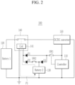
- FIG. 2 shows an operation for supplying a power voltage when a power supply of FIG. 1 is driven in an earlier stage.
- FIG. 3 shows an operation for supplying a power voltage after a power supply of FIG. 1 is driven in an earlier stage.
- a current path P1 may be connected between the second battery 130 and the coil 141 of the relay 140 by the manually manipulated switch SW2. Accordingly, the relay 140 is switched to be closed by the output voltage of the second battery 130, and the output voltage of the first battery 120 may be transmitted to the DC/DC converter 150 through the relay 140.
- the output voltage of the DC/DC converter 150 may be supplied to the controller 110 and the controller 110 may start to be operated.
- the controller 110 may control the switch SW1 to be closed so that the relay 140 may be continuously driven.
- a current path P2 is connected between the DC/DC converter 150 and the coil 141 of the relay 140, and the relay 140 may be controlled to be closed by the output voltage of the DC/DC converter 150. Therefore, the relay 140 may be continuously closed when the switch SW2 is opened.
- the controller 110 may open the relay 140 by opening the switch SW1.
- the DC/DC converter 150 may be driven by controlling the relay 140 to be closed by manipulating the switch SW2.
- the power supply 100 may further include a charging circuit for charging the second battery 130 by using the output voltage of the DC/DC converter 150.
- the charging circuit may include a diode D3.
- An anode of the diode D3 may be electrically connected to a node between the switch SW1 and the diode D1, and a cathode thereof may be electrically connected to the second battery 130.
- FIG. 4 shows an operation for charging a second battery in a power supply of FIG. 1 .
- a current path P3 may be connected between the DC/DC converter 150 and the second battery 130 by the diode D3.
- the output voltage of the DC/DC converter 150 may be transmitted to the second battery 130 through the current path P3, and the second battery 130 may then be charged.
- the output voltage of the DC/DC converter 150 may be reduced by a predetermined voltage (e.g., about 0.3V to 0.7V) by the diode D3 and the reduced output voltage of the DC/DC converter 150 may then be transmitted to the second battery 130, thereby delaying a deterioration rate of the second battery 130.
- the power supply 100 may reduce power consumption by using the relay 140 and blocking the input voltage of the DC/DC converter 150 for supplying an operation voltage to the controller 110.
- the switch SW2 that may be manually manipulated and temporarily providing the output of the second battery 130 to the relay 140.
- the charging voltage of the second battery 130 may be maintained by configuring the circuit so that the second battery 130 may be charged by the output of the DC/DC converter 150 when the DC/DC converter 150 is operated.
Landscapes
- Engineering & Computer Science (AREA)
- Power Engineering (AREA)
- Business, Economics & Management (AREA)
- Emergency Management (AREA)
- Manufacturing & Machinery (AREA)
- Chemical & Material Sciences (AREA)
- Chemical Kinetics & Catalysis (AREA)
- Electrochemistry (AREA)
- General Chemical & Material Sciences (AREA)
- Microelectronics & Electronic Packaging (AREA)
- Charge And Discharge Circuits For Batteries Or The Like (AREA)
Abstract
Description
- The present disclosure relates to a power supply of a battery pack.
- An energy storage system (ESS) stores a large amount of electrical energy and supplies the stored electrical energy when it is needed to improve energy use efficiency. The energy storage system (ESS) includes a high-voltage battery pack for storing electrical energy, and a battery management system (BMS) for monitoring states of the battery pack and control charging and discharging of the battery pack.
- Typically, the energy storage system uses a switched mode power supply (SMPS) to supply a control voltage (e.g., an operation voltage of the BMS) to the battery pack. The switched mode power supply (SMPS) converts an alternating current (AC) voltage input by an AC source into a direct current (DC) voltage and supplies the same as a control voltage of the battery pack. This is a relatively inexpensive way to configure the switched mode power supply (SMPS), but requires a costly installation of an AC system power source.
- Therefore, recently, attempts have been made to use not the system power source but an internal power source battery voltage and a DC/DC converter to supply a control voltage to the battery pack in the energy storage system (ESS). However, when using the battery voltage and the DC/DC converter, a method for driving the DC/DC converter is needed while an internal power voltage of the battery pack is blocked and a control voltage is not normally supplied to the battery pack.
- The present disclosure attempts to provide a power supply of a battery pack for supplying an operating power voltage to a controller of the battery pack by driving a DC/DC converter while no initial power voltage is applied.
- An embodiment of the present disclosure provides a power supply including: a first battery, a second battery; a DC/DC converter for converting a first voltage output by the first battery into a second voltage; a controller for using the second voltage as an operation voltage; a relay connected between the first battery and an input terminal of the DC/DC converter and controlling an electrical connection between the first battery and the input terminal of the DC/DC converter; a first switch connected between an output terminal of the DC/DC converter and a coil of the relay and controlling an electrical connection between the output terminal of the DC/DC converter and the coil; and a second switch connected between the second battery and the coil and controlling an electrical connection between the second battery and the coil.
- Opening/closing of the first switch may be controlled by the controller, and the second switch may be a manual switch opened and closed by a physical manipulation.
- The first battery may be a high voltage battery module configuring the battery pack, and the controller may be a battery management system for controlling charging/discharging of the battery pack.
- If an output voltage of the second battery is supplied to the coil by the second switch, the relay may be closed to transmit the first voltage to the DC/DC converter.
- If the second voltage is supplied by the DC/DC converter, the controller may control the first switch to be closed, and if the first switch is closed, an output voltage of the DC/DC converter may be supplied to the coil.
- The power supply may further include a first diode connected between the first switch and the coil and transmitting an output voltage of the DC/DC converter to the coil if the first switch is closed, and a second diode connected between the second switch and the coil and transmitting an output voltage of the second battery to the coil if the second switch is closed.
- The power supply may further include a third diode connected between the first switch and the second battery and transmitting an output voltage of the DC/DC converter as a charging voltage of the second battery if the first switch is closed.
- According to the present disclosure, the power supply of the battery pack may be manufactured with a low cost by using the internal voltage of the battery pack and the DC/DC converter to supply the control voltage to the battery pack.
- Further, the operating power voltage may be supplied to the controller of the battery pack by driving the DC/DC converter while no initial power voltage is input.
- At least some of the above features that accord with the invention and other features according to the invention are set out in the claims.
-
-
FIG. 1 shows a power supply of a high-voltage battery pack according to an embodiment. -
FIG. 2 shows an operation for supplying a power voltage when a power supply is driven in an earlier stage according to an embodiment. -
FIG. 3 shows an operation for supplying a power voltage after a power supply is driven in an earlier stage according to an embodiment. -
FIG. 4 shows an operation for charging a second battery in a power supply according to an embodiment. - Embodiments of the present invention will now be described in detail with accompanying drawings. Effects and characteristics of embodiments, and a realization method thereof, will now be described in detail with accompanying drawings. In the drawings, same reference numerals indicate same constituent elements, and no repeated descriptions thereof will be provided. As those skilled in the art would realize, the described embodiments may be modified in various different ways, all without departing from the scope of the claims. The embodiments are provided as examples to convey aspects and characteristics of the present invention to a person skilled in the art.
- Hence, for the purpose of understanding aspects and characteristics of the present invention, processes, factors, and skills that are within the common general knowledge of a person of ordinary skill in the art may not be described. Relative sizes of elements, layers, and regions may be exaggerated for clarity.
- In the present specification, the term "and/or" includes all or random combinations of a plurality of items that are related and arranged. When the embodiments of the present invention are described, the use of "may" signifies "at least one embodiment of the present invention". A singular term may include a plural form unless stated in another way.
- Terms including ordinal numbers such as first, second, and the like will be used only to describe various components, and are not to be interpreted as limiting these components. The terms are only used to differentiate one component from other components. For example, a first constituent element could be termed a second constituent element, and similarly, a second constituent element could be termed a first constituent element, without departing from the scope of the present invention.
- In the present document, when one component or layer is described as "on", "connected", or "coupled" for other components or layers, "on", "connected" and "coupled" include all formed directly or by interposing one or more other components or layers. In addition, when it is disclosed that one component or a layer is "between" two components or layers, it should be appreciated that the corresponding component or layer is a single component or layer or there are one or more interposed other elements or layers.
- Electric connection of two constituent elements includes not only a case where the two constituent elements are directly connected, but also a case where the two constituent elements are connected through another constituent element interposed therebetween. Other constituent elements may include a switch, a resistor, a capacitor, and the like. In describing the embodiments, the expression "connection" means electrical connection unless there is an expression "direct connection".
- A power supply of a battery pack according to embodiments will now be described with reference to accompanying drawings.
-
FIG. 1 shows a power supply of a high-voltage battery pack according to an embodiment. - Referring to
FIG. 1 , thepower supply 100 of the high voltage battery pack according to an embodiment may include acontroller 110, afirst battery 120, arelay 140, and a DC/DC converter 150. - The
controller 110 may be a battery management system (BMS) for monitoring the high voltage battery pack and controlling charging/discharging of the high voltage battery pack. Thecontroller 110 may control a supplying of power voltage to acoil 141 of therelay 140 and may control opening/closing of therelay 140. - The
first battery 120 may be a high-voltage battery module configuring the high voltage battery pack. For example, thefirst battery 120 may be a battery module in which a plurality of cells are connected in series or in parallel and which may provide an output voltage of about 1000V. - The
relay 140 may be connected between thefirst battery 120 and an input terminal of the DC/DC converter 150, and may selectively transmit an output voltage of thefirst battery 120 to the DC/DC converter 150. Therelay 140 may switch contact state of nodes by a current flowing to thecoil 141, may transmit an output voltage of thefirst battery 120 to the DC/DC converter 150 in a node contacting state, and may block the output voltage of thefirst battery 120 from being transmitted to the DC/DC converter 150 in a node opening state. - The DC/
DC converter 150 may, when receiving the output voltage of thefirst battery 120 through therelay 140, convert the output voltage into another level of voltage and may output the same. For example, the DC/DC converter 150 may, when receiving the voltage of 1000V from thefirst battery module 110, may convert it into the voltage of 24V and may output the same. The voltage supplied through the output terminal of the DC/DC converter 150 may be supplied as an operation voltage of thecontroller 110. - According to what is described in the above, regarding the
power supply 100, when therelay 140 is closed (i.e., in a node contacting state), the voltage of thefirst battery 120 is supplied to the DC/DC converter 150 so the DC/DC converter 150 may supply an operation voltage of thecontroller 110. When there is no need to supply the operation voltage to thecontroller 110, power consumption may be reduced by opening therelay 140. - In this case, however, when the
relay 140 is opened, it is also blocked to supply a power voltage to the DC/DC converter 150 and thecontroller 110, so a method for controlling therelay 140 to be closed (i.e., a node contacting state) while therelay 140 is opened, and starting to supply the power voltage to the DC/DC converter 150 and thecontroller 110 is needed. Thepower supply 100 may, to solve this problem, operate therelay 140 by using thesecond battery 130 at its initial driving to supply the power voltage to the DC/DC converter 150 and thecontroller 110. - To achieve this, the
power supply 100 may include asecond battery 130, two switches SW1 and SW2, and two diodes D1 and D2. - The
second battery 130 may be a charged/discharged battery module for supplying power in an emergency such as a supplying of power for a firefighting in an energy storage system (ESS) including a high voltage battery pack. For example, thesecond battery 130 may be a battery module for providing the output voltage of about 24V. The person skilled in the art will appreciate that the 24V value is just an example, as is the 1000V example for the first battery. The invention is not limited to any particular voltage values for either the first or the second battery. In embodiments, the first battery a higher voltage than the second battery. - In embodiments, the first battery may comprise a high voltage battery module, wherein the high voltage battery module, may be suitable for powering electric vehicles, whereas the second battery may be suitable for powering electronic circuits.
- The switch SW1 and the diode D1 may be electrically connected between an output terminal of the DC/
DC converter 150 and thecoil 141 of therelay 140, and may selectively transmit the output voltage of the DC/DC converter 150 to thecoil 141 of therelay 140. The switch SW2 and the diode D2 may be electrically connected between thesecond battery 130 and thecoil 141 of therelay 140, and may selectively transmit the output voltage of thesecond battery 130 to thecoil 141 of therelay 140. - The switch SW1 may be electrically connected between an output terminal of the DC/
DC converter 150 and the diode D1, and its opening/closing may be controlled by thecontroller 110. When the switch SW1 is closed, it may transmit the output voltage of the DC/DC converter 150 to the diode D1. When the switch SW1 is opened, it may block the output voltage of the DC/DC converter 150 from being transmitted to the diode D1. The switch SW1 may be a switch of which opening/closing is controlled by electrical signals generated by a relay, a contactor, or a semiconductor switch. - The switch SW2 may be electrically connected between the
second battery 130 and the diode D2, and its opening/closing may be manually controlled by a manager. When the switch SW2 is closed, it may transmit the output voltage of thesecond battery 130 to the diode D2. When the switch SW2 is opened, it may prevent the output voltage of thesecond battery 130 from being transmitted to the diode D2. The switch SW2 may be a switch of which opening/closing is manually controlled by a physical manipulation of such as a push switch. In other words, the second switch, SW2, is a manual switch, controllable by a human operator. - An anode of the diode D1 may be electrically connected to the switch SW1, and a cathode thereof may be electrically connected to the
coil 141 of therelay 140. An anode of the diode D2 may be electrically connected to the switch SW2, and a cathode thereof may be electrically connected to thecoil 141 of therelay 140. - The diodes D1 and D2 may be operable as an OR circuit, and may transmit the output voltage of the DC/
DC converter 150 or the output voltage of thesecond battery 130 as the driving voltage of thecoil 141 of therelay 140. -
FIG. 2 shows an operation for supplying a power voltage when a power supply ofFIG. 1 is driven in an earlier stage.FIG. 3 shows an operation for supplying a power voltage after a power supply ofFIG. 1 is driven in an earlier stage. - Referring to
FIG. 2 , when thepower supply 100 is initially driven, a current path P1 may be connected between thesecond battery 130 and thecoil 141 of therelay 140 by the manually manipulated switch SW2. Accordingly, therelay 140 is switched to be closed by the output voltage of thesecond battery 130, and the output voltage of thefirst battery 120 may be transmitted to the DC/DC converter 150 through therelay 140. The output voltage of the DC/DC converter 150 may be supplied to thecontroller 110 and thecontroller 110 may start to be operated. - Referring to
FIG. 3 , thecontroller 110 may control the switch SW1 to be closed so that therelay 140 may be continuously driven. Hence, a current path P2 is connected between the DC/DC converter 150 and thecoil 141 of therelay 140, and therelay 140 may be controlled to be closed by the output voltage of the DC/DC converter 150. Therefore, therelay 140 may be continuously closed when the switch SW2 is opened. - While the high voltage battery pack is operated, the supplying of a control power voltage by the high voltage battery pack may be blocked because of an over-discharge of the
first battery 120. In this case, thecontroller 110 may open therelay 140 by opening the switch SW1. When it is needed to supply the control power voltage to the high voltage battery pack, the DC/DC converter 150 may be driven by controlling therelay 140 to be closed by manipulating the switch SW2. - Referring to
FIG. 1 , thepower supply 100 may further include a charging circuit for charging thesecond battery 130 by using the output voltage of the DC/DC converter 150. The charging circuit may include a diode D3. An anode of the diode D3 may be electrically connected to a node between the switch SW1 and the diode D1, and a cathode thereof may be electrically connected to thesecond battery 130. -
FIG. 4 shows an operation for charging a second battery in a power supply ofFIG. 1 . - Referring to
FIG. 4 , when the switch SW1 is closed, a current path P3 may be connected between the DC/DC converter 150 and thesecond battery 130 by the diode D3. The output voltage of the DC/DC converter 150 may be transmitted to thesecond battery 130 through the current path P3, and thesecond battery 130 may then be charged. In this instance, the output voltage of the DC/DC converter 150 may be reduced by a predetermined voltage (e.g., about 0.3V to 0.7V) by the diode D3 and the reduced output voltage of the DC/DC converter 150 may then be transmitted to thesecond battery 130, thereby delaying a deterioration rate of thesecond battery 130. - According to the embodiment, when no operation of the
controller 110 is needed, thepower supply 100 may reduce power consumption by using therelay 140 and blocking the input voltage of the DC/DC converter 150 for supplying an operation voltage to thecontroller 110. - It is also possible to supply the power voltage to the DC/
DC converter 150 and thecontroller 110 by using the switch SW2 that may be manually manipulated and temporarily providing the output of thesecond battery 130 to therelay 140. Further, the charging voltage of thesecond battery 130 may be maintained by configuring the circuit so that thesecond battery 130 may be charged by the output of the DC/DC converter 150 when the DC/DC converter 150 is operated. - The accompanying drawings and the embodiments of the present invention are only examples of the present invention, and are used to describe the present invention but do not limit the scope of the present invention as defined by the following claims. It will be understood by those of ordinary skill in the art that various modifications and equivalent embodiments may be made. Therefore, the technical scope of the present invention is defined by the following claims.
-
- 100: power supply
- 110: controller
- 120: first battery
- 130: second battery
- 140: relay
- 141: relay coil
- 150: DC/DC converter
- SW1, SW2: switch
- D1, D2, D3: diode
Claims (6)
- A power supply of a battery pack comprising:a first battery;a second battery;a DC/DC converter for converting a first voltage output by the first battery into a second voltage;a controller configured to use the second voltage as an operation voltage;a relay connected between the first battery and an input terminal of the DC/DC converter and configured to control an electrical connection between the first battery and the input terminal of the DC/DC converter;a first switch connected between an output terminal of the DC/DC converter and a coil of the relay and configured to control an electrical connection between the output terminal of the DC/DC converter and the coil; anda second switch connected between the second battery and the coil and configured to control an electrical connection between the second battery and the coil,wherein the controller is configured to control opening and closing of the first switch, and the second switch is a manual switch openable and closable by a physical manipulation.
- The power supply of claim 1, wherein
the first battery is a high voltage battery module, and the controller is a battery management system for controlling charging/discharging of the battery pack. - The power supply of claim 1 or claim 2, wherein
the relay is configured to be closable to transmit the first voltage to the DC/DC converter, in response to an output voltage of the second battery being supplied to the coil by the second switch. - The power supply of any preceding claim, wherein the controller is configured to:control the first switch to be closed, if the second voltage is supplied by the DC/DC converter; andsupply an output voltage of the DC/DC converter to the coil, if the first switch is closed.
- The power supply of any preceding claim, further comprising:a first diode connected between the first switch and the coil and configured to transmit an output voltage of the DC/DC converter to the coil if the first switch is closed, anda second diode connected between the second switch and the coil and configured to transmit an output voltage of the second battery to the coil if the second switch is closed.
- The power supply of any preceding claim, further comprising
a third diode connected between the first switch and the second battery and configured to transmit an output voltage of the DC/DC converter as a charging voltage of the second battery if the first switch is closed.
Applications Claiming Priority (1)
| Application Number | Priority Date | Filing Date | Title |
|---|---|---|---|
| KR1020220166854A KR20240082824A (en) | 2022-12-02 | 2022-12-02 | Power supply device for battery pack |
Publications (2)
| Publication Number | Publication Date |
|---|---|
| EP4379901A1 true EP4379901A1 (en) | 2024-06-05 |
| EP4379901B1 EP4379901B1 (en) | 2025-11-19 |
Family
ID=88093601
Family Applications (1)
| Application Number | Title | Priority Date | Filing Date |
|---|---|---|---|
| EP23197936.0A Active EP4379901B1 (en) | 2022-12-02 | 2023-09-18 | Power supply for battery pack |
Country Status (5)
| Country | Link |
|---|---|
| US (1) | US20240186817A1 (en) |
| EP (1) | EP4379901B1 (en) |
| KR (1) | KR20240082824A (en) |
| CN (1) | CN118137597A (en) |
| PL (1) | PL4379901T3 (en) |
Citations (2)
| Publication number | Priority date | Publication date | Assignee | Title |
|---|---|---|---|---|
| US20160164328A1 (en) * | 2014-12-03 | 2016-06-09 | Samsung Sdi Co., Ltd. | Battery pack |
| US20200290479A1 (en) * | 2019-03-12 | 2020-09-17 | Takeuchi Mfg. Co., Ltd. | Direct current power supply circuit mounted in working vehicle |
-
2022
- 2022-12-02 KR KR1020220166854A patent/KR20240082824A/en active Pending
-
2023
- 2023-09-12 CN CN202311183278.2A patent/CN118137597A/en active Pending
- 2023-09-18 PL PL23197936.0T patent/PL4379901T3/en unknown
- 2023-09-18 EP EP23197936.0A patent/EP4379901B1/en active Active
- 2023-09-28 US US18/374,433 patent/US20240186817A1/en active Pending
Patent Citations (2)
| Publication number | Priority date | Publication date | Assignee | Title |
|---|---|---|---|---|
| US20160164328A1 (en) * | 2014-12-03 | 2016-06-09 | Samsung Sdi Co., Ltd. | Battery pack |
| US20200290479A1 (en) * | 2019-03-12 | 2020-09-17 | Takeuchi Mfg. Co., Ltd. | Direct current power supply circuit mounted in working vehicle |
Also Published As
| Publication number | Publication date |
|---|---|
| EP4379901B1 (en) | 2025-11-19 |
| US20240186817A1 (en) | 2024-06-06 |
| PL4379901T3 (en) | 2026-03-09 |
| KR20240082824A (en) | 2024-06-11 |
| CN118137597A (en) | 2024-06-04 |
Similar Documents
| Publication | Publication Date | Title |
|---|---|---|
| US7282814B2 (en) | Battery controller and method for controlling a battery | |
| EP3262736B1 (en) | Emergency power supply unit and method for operating an emergency lighting means | |
| CN106464006B (en) | uninterruptible power supply unit | |
| US11848581B2 (en) | Source bootstrap power conversion for the safe and efficient interconnection of homogeneous or heterogeneous energy storage modules | |
| CN109245220B (en) | Charging and discharging current-limiting battery pack parallel control device and control method with minimum switch | |
| US12275329B2 (en) | Multi-voltage storage system for an at least partially electrically driven vehicle | |
| KR102819932B1 (en) | Battery system | |
| JP2020031471A (en) | In-vehicle power supply | |
| US20230048191A1 (en) | Battery cell balance circuit and method of operating the same | |
| KR100451637B1 (en) | A Management System for the Rechargeable Battery | |
| EP4379901A1 (en) | Power supply for battery pack | |
| US20090315402A1 (en) | Ac-dc conversion device | |
| WO2019073652A1 (en) | Electricity storage module and power supply system | |
| US20240317110A1 (en) | Vehicle On-Board Electrical System Including A Battery Connection Circuit Having A Converter And Configurably Connectable Load Terminals On Either Side Of The DC-DC Converter | |
| KR20210007554A (en) | Power system | |
| US20230391228A1 (en) | Power supply device | |
| KR20220015402A (en) | Methods and devices for energy harvesting and charging rechargeable energy storage devices | |
| WO2012032621A1 (en) | Power storage apparatus using capacitor, charging control apparatus therefor, and charging control method therefor | |
| EP3560060B1 (en) | High power flash battery system and method thereof | |
| CN119968748A (en) | DC transformer arrangement, energy supply system and method for discharging an intermediate circuit capacitor | |
| CN112821546A (en) | Multi-battery uninterrupted power supply device, X-ray imaging system and power supply control method | |
| AU2022225664A1 (en) | Device for the concomitant storage and generation of at least one voltage, and associated management method | |
| US20160276850A1 (en) | Charging Bus | |
| EP3772154A1 (en) | A power supply system, and an uninterruptible power supply including the power supply system | |
| EP4579999A1 (en) | Backup power supply for a bms controller |
Legal Events
| Date | Code | Title | Description |
|---|---|---|---|
| PUAI | Public reference made under article 153(3) epc to a published international application that has entered the european phase |
Free format text: ORIGINAL CODE: 0009012 |
|
| STAA | Information on the status of an ep patent application or granted ep patent |
Free format text: STATUS: REQUEST FOR EXAMINATION WAS MADE |
|
| 17P | Request for examination filed |
Effective date: 20230918 |
|
| AK | Designated contracting states |
Kind code of ref document: A1 Designated state(s): AL AT BE BG CH CY CZ DE DK EE ES FI FR GB GR HR HU IE IS IT LI LT LU LV MC ME MK MT NL NO PL PT RO RS SE SI SK SM TR |
|
| GRAP | Despatch of communication of intention to grant a patent |
Free format text: ORIGINAL CODE: EPIDOSNIGR1 |
|
| STAA | Information on the status of an ep patent application or granted ep patent |
Free format text: STATUS: GRANT OF PATENT IS INTENDED |
|
| INTG | Intention to grant announced |
Effective date: 20250711 |
|
| GRAS | Grant fee paid |
Free format text: ORIGINAL CODE: EPIDOSNIGR3 |
|
| GRAA | (expected) grant |
Free format text: ORIGINAL CODE: 0009210 |
|
| STAA | Information on the status of an ep patent application or granted ep patent |
Free format text: STATUS: THE PATENT HAS BEEN GRANTED |
|
| AK | Designated contracting states |
Kind code of ref document: B1 Designated state(s): AL AT BE BG CH CY CZ DE DK EE ES FI FR GB GR HR HU IE IS IT LI LT LU LV MC ME MK MT NL NO PL PT RO RS SE SI SK SM TR |
|
| REG | Reference to a national code |
Ref country code: CH Ref legal event code: F10 Free format text: ST27 STATUS EVENT CODE: U-0-0-F10-F00 (AS PROVIDED BY THE NATIONAL OFFICE) Effective date: 20251119 Ref country code: GB Ref legal event code: FG4D |
|
| REG | Reference to a national code |
Ref country code: DE Ref legal event code: R096 Ref document number: 602023008732 Country of ref document: DE |
|
| REG | Reference to a national code |
Ref country code: IE Ref legal event code: FG4D |
|
| REG | Reference to a national code |
Ref country code: NL Ref legal event code: MP Effective date: 20251119 |
|
| PG25 | Lapsed in a contracting state [announced via postgrant information from national office to epo] |
Ref country code: ES Free format text: LAPSE BECAUSE OF FAILURE TO SUBMIT A TRANSLATION OF THE DESCRIPTION OR TO PAY THE FEE WITHIN THE PRESCRIBED TIME-LIMIT Effective date: 20251119 |
|
| REG | Reference to a national code |
Ref country code: LT Ref legal event code: MG9D |
|
| PG25 | Lapsed in a contracting state [announced via postgrant information from national office to epo] |
Ref country code: NO Free format text: LAPSE BECAUSE OF FAILURE TO SUBMIT A TRANSLATION OF THE DESCRIPTION OR TO PAY THE FEE WITHIN THE PRESCRIBED TIME-LIMIT Effective date: 20260219 |
|
| PG25 | Lapsed in a contracting state [announced via postgrant information from national office to epo] |
Ref country code: AT Free format text: LAPSE BECAUSE OF FAILURE TO SUBMIT A TRANSLATION OF THE DESCRIPTION OR TO PAY THE FEE WITHIN THE PRESCRIBED TIME-LIMIT Effective date: 20251119 Ref country code: HR Free format text: LAPSE BECAUSE OF FAILURE TO SUBMIT A TRANSLATION OF THE DESCRIPTION OR TO PAY THE FEE WITHIN THE PRESCRIBED TIME-LIMIT Effective date: 20251119 Ref country code: FI Free format text: LAPSE BECAUSE OF FAILURE TO SUBMIT A TRANSLATION OF THE DESCRIPTION OR TO PAY THE FEE WITHIN THE PRESCRIBED TIME-LIMIT Effective date: 20251119 |
|
| REG | Reference to a national code |
Ref country code: AT Ref legal event code: MK05 Ref document number: 1859662 Country of ref document: AT Kind code of ref document: T Effective date: 20251119 |
|
| PG25 | Lapsed in a contracting state [announced via postgrant information from national office to epo] |
Ref country code: NL Free format text: LAPSE BECAUSE OF FAILURE TO SUBMIT A TRANSLATION OF THE DESCRIPTION OR TO PAY THE FEE WITHIN THE PRESCRIBED TIME-LIMIT Effective date: 20251119 |
|
| PG25 | Lapsed in a contracting state [announced via postgrant information from national office to epo] |
Ref country code: RS Free format text: LAPSE BECAUSE OF FAILURE TO SUBMIT A TRANSLATION OF THE DESCRIPTION OR TO PAY THE FEE WITHIN THE PRESCRIBED TIME-LIMIT Effective date: 20260219 |
|
| PG25 | Lapsed in a contracting state [announced via postgrant information from national office to epo] |
Ref country code: IS Free format text: LAPSE BECAUSE OF FAILURE TO SUBMIT A TRANSLATION OF THE DESCRIPTION OR TO PAY THE FEE WITHIN THE PRESCRIBED TIME-LIMIT Effective date: 20260319 |
|
| PG25 | Lapsed in a contracting state [announced via postgrant information from national office to epo] |
Ref country code: PT Free format text: LAPSE BECAUSE OF FAILURE TO SUBMIT A TRANSLATION OF THE DESCRIPTION OR TO PAY THE FEE WITHIN THE PRESCRIBED TIME-LIMIT Effective date: 20260319 |
|
| PG25 | Lapsed in a contracting state [announced via postgrant information from national office to epo] |
Ref country code: LV Free format text: LAPSE BECAUSE OF FAILURE TO SUBMIT A TRANSLATION OF THE DESCRIPTION OR TO PAY THE FEE WITHIN THE PRESCRIBED TIME-LIMIT Effective date: 20251119 |