EP4379693A1 - Fatigue monitoring camera mounting structure, instrument panel assembly and automobile - Google Patents
Fatigue monitoring camera mounting structure, instrument panel assembly and automobile Download PDFInfo
- Publication number
- EP4379693A1 EP4379693A1 EP21951159.9A EP21951159A EP4379693A1 EP 4379693 A1 EP4379693 A1 EP 4379693A1 EP 21951159 A EP21951159 A EP 21951159A EP 4379693 A1 EP4379693 A1 EP 4379693A1
- Authority
- EP
- European Patent Office
- Prior art keywords
- steering column
- electrical component
- component assembly
- mounting structure
- connecting rod
- Prior art date
- Legal status (The legal status is an assumption and is not a legal conclusion. Google has not performed a legal analysis and makes no representation as to the accuracy of the status listed.)
- Pending
Links
Images



Classifications
-
- B—PERFORMING OPERATIONS; TRANSPORTING
- B60—VEHICLES IN GENERAL
- B60R—VEHICLES, VEHICLE FITTINGS, OR VEHICLE PARTS, NOT OTHERWISE PROVIDED FOR
- B60R11/00—Arrangements for holding or mounting articles, not otherwise provided for
- B60R11/04—Mounting of cameras operative during drive; Arrangement of controls thereof relative to the vehicle
-
- G—PHYSICS
- G08—SIGNALLING
- G08B—SIGNALLING SYSTEMS, e.g. PERSONAL CALLING SYSTEMS; ORDER TELEGRAPHS; ALARM SYSTEMS
- G08B21/00—Alarms responsive to a single specified undesired or abnormal condition and not otherwise provided for
- G08B21/02—Alarms for ensuring the safety of persons
- G08B21/06—Alarms for ensuring the safety of persons indicating a condition of sleep, e.g. anti-dozing alarms
-
- B—PERFORMING OPERATIONS; TRANSPORTING
- B60—VEHICLES IN GENERAL
- B60R—VEHICLES, VEHICLE FITTINGS, OR VEHICLE PARTS, NOT OTHERWISE PROVIDED FOR
- B60R11/00—Arrangements for holding or mounting articles, not otherwise provided for
- B60R2011/0001—Arrangements for holding or mounting articles, not otherwise provided for characterised by position
- B60R2011/0003—Arrangements for holding or mounting articles, not otherwise provided for characterised by position inside the vehicle
- B60R2011/001—Vehicle control means, e.g. steering-wheel or column
-
- B—PERFORMING OPERATIONS; TRANSPORTING
- B60—VEHICLES IN GENERAL
- B60R—VEHICLES, VEHICLE FITTINGS, OR VEHICLE PARTS, NOT OTHERWISE PROVIDED FOR
- B60R11/00—Arrangements for holding or mounting articles, not otherwise provided for
- B60R2011/0042—Arrangements for holding or mounting articles, not otherwise provided for characterised by mounting means
- B60R2011/0049—Arrangements for holding or mounting articles, not otherwise provided for characterised by mounting means for non integrated articles
- B60R2011/005—Connection with the vehicle part
- B60R2011/0057—Connection with the vehicle part using magnetic means
-
- B—PERFORMING OPERATIONS; TRANSPORTING
- B60—VEHICLES IN GENERAL
- B60R—VEHICLES, VEHICLE FITTINGS, OR VEHICLE PARTS, NOT OTHERWISE PROVIDED FOR
- B60R2300/00—Details of viewing arrangements using cameras and displays, specially adapted for use in a vehicle
- B60R2300/80—Details of viewing arrangements using cameras and displays, specially adapted for use in a vehicle characterised by the intended use of the viewing arrangement
- B60R2300/8006—Details of viewing arrangements using cameras and displays, specially adapted for use in a vehicle characterised by the intended use of the viewing arrangement for monitoring and displaying scenes of vehicle interior, e.g. for monitoring passengers or cargo
-
- B—PERFORMING OPERATIONS; TRANSPORTING
- B62—LAND VEHICLES FOR TRAVELLING OTHERWISE THAN ON RAILS
- B62D—MOTOR VEHICLES; TRAILERS
- B62D1/00—Steering controls, i.e. means for initiating a change of direction of the vehicle
- B62D1/02—Steering controls, i.e. means for initiating a change of direction of the vehicle vehicle-mounted
- B62D1/16—Steering columns
- B62D1/18—Steering columns yieldable or adjustable, e.g. tiltable
Definitions
- the present document relates to a field of automotive camera structure, in particular to a fatigue monitoring camera mounting structure, an instrument panel assembly, and an automobile.
- the present document provides a fatigue monitoring camera mounting structure, which solves the problem in the existing technology of requiring large collapse space in the instrument panel and affecting the appearance design of the instrument panel in case the electrical component assembly is fixed to the steering column shield.
- a fatigue monitoring camera mounting structure including:
- the electrical component assembly matches with the steering wheel during the process that the steering column shield moves toward a collapsing direction until it is separated from the electrical component assembly.
- the electrical component assembly and the steering wheel do not interfere with each other during the separation process of the steering column shield and the electrical component assembly. This allows the steering column shield to drive the steering wheel to complete a collision collapse response in the collapse direction, thereby ensuring the safety performance of the steering wheel during collision.
- one of a lower surface of the electrical component assembly and the steering column shield is equipped with a first groove, and a length of which is in an axial direction of the steering column, and the other of the lower surface of the electrical component assembly and the steering column shield is equipped with a first protrusion, which is located in the first groove.
- One of the first protrusion and the first groove is equipped with the magnetic member, the other of the first protrusion and the first groove is equipped with a ferromagnetic body.
- a length of the first groove is greater than or equal to a length of the first protrusion.
- the first groove is a strip groove
- the first protrusion is a strip protrusion
- first connecting rod a first connecting rod
- second connecting rod a second connecting rod
- guide rail bracket a guide rail bracket
- the guide rail bracket is configured for being fixed on a back portion of the instrument panel, and the guide rail bracket is equipped with a sliding groove.
- One end of the first connecting rod is fixedly connected to the electrical component assembly, and the other end of the first connecting rod is fixedly connected to the second connecting rod.
- the second connecting rod passes through the sliding groove and is limited in the sliding groove along an axial direction of the second connecting rod.
- the second connecting rod is capable of sliding up and down along the sliding groove when the steering wheel is adjusted up and down.
- the guide rail bracket is equipped with two side wings, and the sliding groove is arranged on a corresponding side wing.
- the second connecting rod is equipped with two clamping portions close to two ends thereof, and the second connecting rod passes through the sliding groove with the clamping portions abutting against inner sides of corresponding side wings.
- the instrument panel is equipped with an avoidance opening, and widths of the electrical component assembly and the steering column shield are both less than or equal to a width of the avoidance opening.
- the soft cover is fixedly connected between the electrical component assembly and the instrument panel.
- the soft cover is configured for shielding the first connecting rod, the second connecting rod, and the guide rail bracket.
- an outer surface of the magnetic member is covered with an electroplating protective layer for stabilizing the outer surface of the magnetic member.
- a lubricating grease is added into the first groove.
- an instrument panel assembly which includes the instrument panel and the fatigue monitoring camera mounting structure mentioned above.
- the fatigue monitoring camera mounting structure includes a guide rail bracket, and the fatigue monitoring camera mounting structure is fixed to a back portion of the instrument panel through the guide rail bracket.
- an automobile which includes the instrument panel assembly mentioned above.
- this embodiment provides a fatigue monitoring camera mounting structure, which includes:
- the electrical component assembly 1 includes a camera, which is configured for monitoring the fatigue state of the driver.
- the steering column shield 2 and the electrical component assembly 1 are connected by the magnetic member 4, which enables the steering column shield 2 to slide back and forth relative to the electrical component assembly 1.
- the steering column shield 2 drives the steering wheel 3 through the steering column to collapse towards an inner side of the instrument panel 8 along an axial direction of the steering column.
- the electrical component assembly 1 remains stationary in the collapse direction.
- the electrical component assembly is fixedly mounted to the steering column shield, so that the electrical component assembly and the steering column shield collapse together towards the inner side of the instrument panel when the steering wheel collapses in a collision. Therefore, it is necessary to reserve a large collapse space in the instrument panel, which affects the appearance design of the instrument panel.
- the electrical component assembly 1 matches the steering wheel 3 during the steering column shield 2 moves towards the collapse direction and separates from the electrical component assembly 1.
- a bottom portion of the steering wheel 3 and the steering column shield 2 gradually moves below the electrical component assembly 1. Due to the shape of the lower surface of the electrical component assembly 1 matches the shape of the bottom portion of the steering wheel 3, the electrical component assembly 1 and the steering wheel 3 do not interference with each other during the separation process of the steering column shield 2 and the electrical component assembly 1, thereby making the steering column shield 2 take the steering wheel 3 to complete a collision collapse response in the collapse direction, and ensuring the safety performance of the steering wheel 3 during the collision process.
- one of them is equipped with a first groove 11, a length of which is in an axial direction of the steering column, and the other is equipped with a first protrusion 21 and the first protrusion 21 is located in the first groove 11.
- the first protrusion 21 and the first groove 11 one is equipped with the magnetic member 4 and the other is equipped with a ferromagnetic body.
- the number of the first protrusion 21 and the first groove 11 are both two, and a width of the first protrusion 21 matches a width of the first groove 11.
- the width direction is a direction perpendicular to an axial direction of the steering column at a top surface of the steering column shield 2, thereby achieving a position limitation between the electrical component assembly 1 and the steering column shield 2 and a good guiding effect, which facilitates relative sliding between the steering column shield 2 and the electrical component assembly 1 in a collision and collapse of the steering wheel 3, and meets the requirement for collapse safety.
- the magnetic member 4 is made of magnet, while the ferromagnetic body is made of materials such as steel or copper that are easily adsorbed by the magnetic member.
- the length of the first groove 11 is greater than or equal to the length of the first protrusion 21, and the length direction is in the axial direction of the steering column, so that the steering column shield 2 can take the steering wheel 3 to slide back and forth relative to the electrical component assembly 1, thereby achieving a back and forth adjustment function of the steering wheel 3.
- the first groove 11 is a strip groove
- the first protrusion 21 is a strip protrusion
- the magnetic member 4 includes multiple discrete magnetic pieces.
- the first protrusion 21 may be multiple discrete protrusions, and the positions of the discrete protrusions match the position of the first groove 11. Correspondingly, multiple discrete magnetic pieces are located inside the multiple discrete protrusions.
- it further includes a first connecting rod 5, a second connecting rod 6, and a guide rail bracket 7.
- the guide rail bracket 7 is configured for fixing on the back portion of the instrument panel 8, and the guide rail bracket 7 is equipped with a sliding groove 71.
- One end of the first connecting rod 5 is fixedly connected to the electrical component assembly 1, and the other end of the first connecting rod 5 is fixedly connected to the second connecting rod 6.
- the second connecting rod 6 passes through the sliding groove 71 and is limited in the sliding groove 71 in the axial direction of the second connecting rod 6.
- the second connecting rod 6 is set to slide up and down along the sliding groove 71 when the steering wheel 3 is adjusted up and down.
- the length direction of the sliding groove 71 is consistent with an up and down adjustment direction of the steering wheel 3, and the width direction of the sliding groove 71 is perpendicular to the up and down adjustment direction of the steering wheel 3.
- the outer diameter of the second connecting rod 6 matches the width of the sliding groove 71, so that when the steering wheel 3 moves back and forth, the second connecting rod 6 does not separate from the guide rail bracket 7 in the back and forth directions.
- the guide rail bracket 7 is equipped with two side wings, and the sliding grooves 71 are arranged on corresponding side wings.
- the second connecting rod 6 are equipped with two clamping portions 61 close to two ends of the second connecting rod 6 respectively.
- the second connecting rod 6 passes through the sliding grooves 71 with the clamping portions 61 abutting against inner sides of the corresponding side wings.
- the guide rail bracket 7 includes an instrument panel mounting surface 71 and the two side wings 73.
- the instrument panel mounting surface 71 is fixedly connected to the two side wings 73, and the two side wings 73 are symmetrically arranged on the back portion of the instrument panel mounting surface 71, and are perpendicular to the instrument panel mounting surface 71.
- the two sliding grooves 71 are symmetrically arranged on the corresponding side wings 73, and a length of the second connecting rod 6 is greater than or equal to a distance between the two side wings 73.
- a length of the clamping portion 61 in the width direction of the sliding groove 71 is greater than a width of the sliding groove 71.
- the instrument panel 8 is equipped with an avoidance opening 81, and the widths of the electrical component assembly 1 and the steering column shield 2 are both less than or equal to the width of the avoidance opening 81.
- the electrical component assembly 1 and the steering column shield 2 correspondingly move up and down within the avoidance opening 81.
- the soft cover 9 is configured for shielding the first connecting rod 5, the second connecting rod 6, and the guide rail bracket 7, improving the overall aesthetics of the mounting structure and the user experience.
- the soft cover 9 is preferably made of PU material.
- the outer surface of the magnetic member 4 is covered with an electroplating protective layer for stabilizing the outer surface of the magnetic member 4.
- an electroplating protective layer for stabilizing the outer surface of the magnetic member 4.
- a lubricating grease is added into the first groove 11, for reducing a friction between the first protrusion 21 and the first groove 11, which helps to the relative movement between the first protrusion 21 and the first groove 11.
- Figure 7 is a schematic diagram of the fatigue monitoring camera mounting structure before and after a downward adjustment of the steering wheel according to an embodiment of the present document.
- Figure 8 is the schematic diagram of the fatigue monitoring camera mounting structure before and after a backward adjustment of the steering wheel according to an embodiment of the present document.
- Figure 9 is a schematic diagram of the fatigue monitoring camera mounting structure before and after the collision and collapse of the steering wheel according to an embodiment of the present document.
- this embodiment provides an instrument panel assembly, which includes an instrument panel 8 and the fatigue monitoring camera mounting structure in Example 1.
- the fatigue monitoring camera mounting structure includes a guide rail bracket 7, and the fatigue monitoring camera mounting structure is fixed to the back portion of the instrument panel 8 through the guide rail bracket 7.
- an instrument panel assembly is formed, which not only achieves semi linkage between the electrical component assembly 1 and the steering column shield 2, but also saves space on the inner side of the instrument panel 8. This helps to achieve a simple structural design of the instrument panel assembly and enhance its aesthetic appearance.
- This embodiment provides an automobile, which includes the instrument panel assembly in Example 2.
- This new structure of the instrument panel assembly By arranging this new structure of the instrument panel assembly on the automobile, it ensures the collision safety while meeting technical requirements, improves space limitation problems, and ensures the overall simplicity of the instrument panel design, thereby making the interior design of the automobile aesthetically pleasing and enhancing the user experience.
Landscapes
- Business, Economics & Management (AREA)
- Emergency Management (AREA)
- Physics & Mathematics (AREA)
- General Physics & Mathematics (AREA)
- Engineering & Computer Science (AREA)
- Mechanical Engineering (AREA)
- Steering Controls (AREA)
Abstract
Description
- The present document relates to a field of automotive camera structure, in particular to a fatigue monitoring camera mounting structure, an instrument panel assembly, and an automobile.
- As automobiles become smarter and safer, it is becoming more and more popular to install fatigue monitoring cameras on the driver's side of the passenger compartment to detect the driver's fatigue status and avoid accidents caused by fatigue driving.
- Common fatigue monitoring cameras are mainly installed and arranged in the following three places:
- 1) Installed and fixed on the A-pillar at the driver's side;
- 2) Integrated with and installed in the instrument cluster;
- 3) Fixed to the steering column shield.
- Although the three common installation layout can all monitor the driver's fatigue status, they also have their own limitations:
- a) If the fatigue monitoring cameras are installed on the A-pillar, due to it is far from the driver's eyes, a high monitoring sensitivity of the camera is required. When the monitoring sensitivity of the camera is insufficient, it is easy to occur inaccurate monitoring;
- b) If the fatigue monitoring cameras are installed in the instrument cluster, it requires the automobile to be equipped with the instrument cluster, which complicates the structure of the instrument panel. Moreover, more and more electric vehicles cancel the instrument cluster, making it unable to be widely used in the electric vehicles;
- c) If the fatigue monitoring cameras are fixed to the steering column shield, it is required that the overall structure of the camera spaces at least 85mm away from the instrument panel to meet the collapse requirements of the steering column during collision. Therefore, there are restrictions on the appearance design of the instrument panel.
- Therefore, it is necessary to provide a fatigue monitoring camera mounting structure that has a simple structure and meets the requirements of collision safety and does not require high camera sensitivity to solve the forgoing technical problems.
- In order to solve the above technical problems, the present document provides a fatigue monitoring camera mounting structure, which solves the problem in the existing technology of requiring large collapse space in the instrument panel and affecting the appearance design of the instrument panel in case the electrical component assembly is fixed to the steering column shield.
- The technical effect of the present document is achieved through the following techniques:
A fatigue monitoring camera mounting structure, including: - An electrical component assembly capable of moving up and down relative to an instrument panel, for detecting a fatigue state of a driver;
- A steering column shield configured for being fixedly sleeved around a steering column, and the steering column being configured for fixedly connected to a steering wheel, a side end of the steering column shield being close to the steering wheel, and the steering column shield being located below the electrical component assembly, the steering column shield or the electrical component assembly being provided with a magnetic member, and the electrical component assembly and the steering column shield being magnetically connected through the magnetic member, the steering column shield being capable of sliding back and forth relative to the electrical component assembly when the steering wheel is adjusted back and forth. By connecting the steering column shield and the electrical component assembly through the magnetic member, a simple and flexible connection structure is achieved, making the electrical component assembly forms a semi-link structure together with the steering column shield. Under different adjustment conditions, the two parts present different linkage effects, saving an internal space in the instrument panel, making the automobile interior more concise, and solving the problem in the existing technology of requiring large collapse space in the instrument panel and affecting the appearance design of the instrument panel in case the electrical component assembly is fixed to the steering column shield.
- Furthermore, when a collision collapse occurs, the electrical component assembly matches with the steering wheel during the process that the steering column shield moves toward a collapsing direction until it is separated from the electrical component assembly. By matching the shape of the electrical component assembly with the shape of the steering wheel, the electrical component assembly and the steering wheel do not interfere with each other during the separation process of the steering column shield and the electrical component assembly. This allows the steering column shield to drive the steering wheel to complete a collision collapse response in the collapse direction, thereby ensuring the safety performance of the steering wheel during collision.
- Furthermore, one of a lower surface of the electrical component assembly and the steering column shield is equipped with a first groove, and a length of which is in an axial direction of the steering column, and the other of the lower surface of the electrical component assembly and the steering column shield is equipped with a first protrusion, which is located in the first groove. One of the first protrusion and the first groove is equipped with the magnetic member, the other of the first protrusion and the first groove is equipped with a ferromagnetic body. By setting the first protrusion and first groove, relative position between the electrical component assembly and the steering column shield is limited, and a good guiding effect is achieved, thereby facilitating a relative sliding between the steering column shield and the electrical component assembly in a collision and collapse of the steering wheel, and meeting a requirement of collapse safety.
- Furthermore, a length of the first groove is greater than or equal to a length of the first protrusion. By setting the length of the first groove to be greater than or equal to the length of the first protrusion, the steering column shield can drive the steering wheel to slide back and forth relative to the electrical component assembly, so as to realize the back and forth adjustment of the steering wheel.
- Furthermore, the first groove is a strip groove, and the first protrusion is a strip protrusion.
- Furthermore, it further includes a first connecting rod, a second connecting rod, and a guide rail bracket.
- The guide rail bracket is configured for being fixed on a back portion of the instrument panel, and the guide rail bracket is equipped with a sliding groove.
- One end of the first connecting rod is fixedly connected to the electrical component assembly, and the other end of the first connecting rod is fixedly connected to the second connecting rod.
- The second connecting rod passes through the sliding groove and is limited in the sliding groove along an axial direction of the second connecting rod. The second connecting rod is capable of sliding up and down along the sliding groove when the steering wheel is adjusted up and down. By setting a sliding groove on the guide rail bracket, and cooperating with the first connecting rod and the second connecting rod, the second connecting rod can slide up and down along the sliding groove, and the steering column shield is adsorbed by the electrical component assembly to drive the steering wheel to move up and down, thereby achieving an up and down adjustment of the steering wheel.
- Furthermore, the guide rail bracket is equipped with two side wings, and the sliding groove is arranged on a corresponding side wing.
- The second connecting rod is equipped with two clamping portions close to two ends thereof, and the second connecting rod passes through the sliding groove with the clamping portions abutting against inner sides of corresponding side wings.
- Furthermore, the instrument panel is equipped with an avoidance opening, and widths of the electrical component assembly and the steering column shield are both less than or equal to a width of the avoidance opening. When the second connecting rod slides up and down along the sliding groove, the electrical component assembly and the steering column shield correspondingly move up and down within the avoidance opening.
- Furthermore, it further includes a soft cover, which is fixedly connected between the electrical component assembly and the instrument panel. The soft cover is configured for shielding the first connecting rod, the second connecting rod, and the guide rail bracket.
- Furthermore, an outer surface of the magnetic member is covered with an electroplating protective layer for stabilizing the outer surface of the magnetic member.
- Furthermore, a lubricating grease is added into the first groove.
- In addition, an instrument panel assembly is also provided, which includes the instrument panel and the fatigue monitoring camera mounting structure mentioned above. The fatigue monitoring camera mounting structure includes a guide rail bracket, and the fatigue monitoring camera mounting structure is fixed to a back portion of the instrument panel through the guide rail bracket.
- In addition, an automobile is also provided, which includes the instrument panel assembly mentioned above.
- As mentioned above, the present document has the following beneficial effects:
- 1) By connecting the steering column shield with the electrical component assembly through the magnetic member, a simple and flexible connection structure is achieved, making the electrical component assembly form a semi-link structure together with the steering column shield. Under different adjustment conditions, the two parts exhibit different linkage effects, saving a space inside the instrument panel and making the automobile interior more concise, solving the problem in the existing technology of requiring large collapse space in the instrument panel and affecting the appearance design of the instrument panel in case the electrical component assembly is fixed on the steering column shield.
- 2) By matching the shape of the electrical component assembly with the shape of the steering wheel, the electrical component assembly and the steering wheel will not interfere with each other during the separation process of the steering column shield and the electrical component assembly. This allows the steering column shield to drive the steering wheel to complete a collision collapse response in the collapse direction, thereby ensuring the safety performance of the steering wheel during collision.
- 3) By setting the first protrusion and the first groove, relative positon between the electrical component assembly and the steering column shield is limited, and a good guiding effect is achieved, thereby facilitating a relative sliding between the steering column shield and the electrical component assembly in a collision and collapse of the steering wheel, and meeting the requirements of collapse safety.
- 4) By setting the length of the first groove to be greater than or equal to the length of the first protrusion, the steering column shield can drive the steering wheel to slide back and forth relative to the electrical component assembly, so as to realize a back and forth adjustment of the steering wheel.
- 5) By setting a sliding groove on the guide rail bracket, and cooperating with the first connecting rod and the second connecting rod, the second connecting rod can slide up and down along the sliding groove, and the steering column shield is adsorbed by the electrical component assembly to drive the steering wheel to move up and down, thereby achieving an up and down adjustment of the steering wheel.
- In order to more clearly illustrate the technical solutions of the present document, the drawings required for the description of the embodiments or the existing technology will be introduced briefly. Obviously, the drawings in the following description only show some of the embodiments of the present document. For those of ordinary skill in the art, other drawings may be obtained based on these drawings without creative work.
-
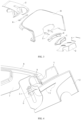
Figure 1 is a schematic, front view of a fatigue monitoring camera mounting structure according to an embodiment of the present document; -
Figure 2 is a schematic, back view of a fatigue monitoring camera mounting structure according to an embodiment of the present document; -
Figure 3 is a schematic, exploded view of a fatigue monitoring camera mounting structure according to an embodiment of the present document; -
Figure 4 is a schematic, cross-sectional view of a fatigue monitoring camera mounting structure according to an embodiment of the present document; -
Figure 5 is a schematic, structural view of an electrical component assembly according to an embodiment of the present document; -
Figure 6 is a schematic, structural view of a steering column shield according to an embodiment of the present document; -
Figure 7 is a schematic view showing the change of the fatigue monitoring camera mounting structure before and after a downward adjustment of the steering wheel according to an embodiment of the present document; -
Figure 8 is a schematic view showing the change of the fatigue monitoring camera mounting structure before and after a backward adjustment of the steering wheel according to an embodiment of the present document; -
Figure 9 is a schematic view showing the change of the fatigue monitoring camera mounting structure before and after the collision and collapse of the steering wheel according to an embodiment of the present document. - Among them, the accompanying symbols in the figure correspond to:
Electrical component assembly 1,first groove 11,steering column shield 2,first protrusion 21,steering wheel 3,magnetic member 4, first connectingrod 5, second connectingrod 6, clampingportion 61,guide rail bracket 7, slidinggroove 71,instrument panel 8,avoidance opening 81, and soft cover 9. - Specific embodiments of the present document will now be clearly and completely described below with reference to the accompanying drawings. Obviously, the described embodiments are only some of the embodiments of the present document, rather than all of the embodiments. Based on the description of the present document, all other embodiments obtained by a person of ordinary skill in the art without creative work shall fall within the protection scope of the present document.
- It should be noted that the terms "first", "second", etc. in the description and claims of the present document, as well as the accompanying drawings, are used to distinguish similar objects, without necessarily describing a specific order or sequence. It is to be understood that the data so used are interchangeable under appropriate circumstances so that the embodiments of the present document described herein can be implemented in sequences other than those illustrated or described herein. In addition, the terms "including" and "having", as well as any variations thereof, are intended to cover non-exclusive inclusions. For example, a process, method, system, product, or apparatus that includes a series of steps or units are not limited to those clearly listed, but may include other steps or units that are not clearly listed or inherent to these process, method, product or apparatus.
- As shown in
Figures 1-6 , this embodiment provides a fatigue monitoring camera mounting structure, which includes: - An
electrical component assembly 1, which can move up and down relative to aninstrument panel 8, and is configured for detecting a fatigue state of a driver, - A
steering column shield 2 configured for being fixedly sleeved around a steering column. The steering column is fixedly connected to asteering wheel 3, and a side end of thesteering column shield 2 is close to thesteering wheel 3. Thesteering column shield 2 is located below theelectrical component assembly 1. Thesteering column shield 2 or theelectrical component assembly 1 is provided with amagnetic member 4, which is configured for adsorbing and fixing theelectrical component assembly 1 onto thesteering column shield 2. Thesteering column shield 2 is capable of sliding back and forth relative to theelectrical component assembly 1 when thesteering wheel 3 is adjusted back and forth. The back and forth directions refer to a forward movement direction when thesteering wheel 3 moves toward the driver and a backward movement direction when thesteering wheel 3 moves away from the driver. - Specifically, the
electrical component assembly 1 includes a camera, which is configured for monitoring the fatigue state of the driver. Thesteering column shield 2 and theelectrical component assembly 1 are connected by themagnetic member 4, which enables thesteering column shield 2 to slide back and forth relative to theelectrical component assembly 1. When the driver collides with thesteering wheel 3, thesteering column shield 2 drives thesteering wheel 3 through the steering column to collapse towards an inner side of theinstrument panel 8 along an axial direction of the steering column. At this time, theelectrical component assembly 1 remains stationary in the collapse direction. - It should be noted that in the existing technology, the electrical component assembly is fixedly mounted to the steering column shield, so that the electrical component assembly and the steering column shield collapse together towards the inner side of the instrument panel when the steering wheel collapses in a collision. Therefore, it is necessary to reserve a large collapse space in the instrument panel, which affects the appearance design of the instrument panel.
- By connecting the
steering column shield 2 and theelectrical component assembly 1 through themagnetic member 4, a simple and flexible connection structure is achieved, making theelectrical component assembly 1 forms a semi-link structure together with thesteering column shield 2. Under different adjustment conditions, the two parts exhibit different linkage effects, saving space inside the instrument panel and making the automobile interior more concise, solving the problem in the existing technology of affecting the appearance design of the instrument panel when the electrical component assembly is fixedly connected to the steering column shield. - Preferably, when a collision occurs, the
electrical component assembly 1 matches thesteering wheel 3 during thesteering column shield 2 moves towards the collapse direction and separates from theelectrical component assembly 1. - Specifically, during the
steering column shield 2 moves towards the collapse direction and separates from theelectrical component assembly 1 in a collision, a bottom portion of thesteering wheel 3 and thesteering column shield 2 gradually moves below theelectrical component assembly 1. Due to the shape of the lower surface of theelectrical component assembly 1 matches the shape of the bottom portion of thesteering wheel 3, theelectrical component assembly 1 and thesteering wheel 3 do not interference with each other during the separation process of thesteering column shield 2 and theelectrical component assembly 1, thereby making thesteering column shield 2 take thesteering wheel 3 to complete a collision collapse response in the collapse direction, and ensuring the safety performance of thesteering wheel 3 during the collision process. - Preferably, between the lower surface of the
electrical component assembly 1 and thesteering column shield 2, one of them is equipped with afirst groove 11, a length of which is in an axial direction of the steering column, and the other is equipped with afirst protrusion 21 and thefirst protrusion 21 is located in thefirst groove 11. Between thefirst protrusion 21 and thefirst groove 11, one is equipped with themagnetic member 4 and the other is equipped with a ferromagnetic body. - In this embodiment, the number of the
first protrusion 21 and thefirst groove 11 are both two, and a width of thefirst protrusion 21 matches a width of thefirst groove 11. The width direction is a direction perpendicular to an axial direction of the steering column at a top surface of thesteering column shield 2, thereby achieving a position limitation between theelectrical component assembly 1 and thesteering column shield 2 and a good guiding effect, which facilitates relative sliding between thesteering column shield 2 and theelectrical component assembly 1 in a collision and collapse of thesteering wheel 3, and meets the requirement for collapse safety. - Specifically, the
magnetic member 4 is made of magnet, while the ferromagnetic body is made of materials such as steel or copper that are easily adsorbed by the magnetic member. - Preferably, the length of the
first groove 11 is greater than or equal to the length of thefirst protrusion 21, and the length direction is in the axial direction of the steering column, so that thesteering column shield 2 can take thesteering wheel 3 to slide back and forth relative to theelectrical component assembly 1, thereby achieving a back and forth adjustment function of thesteering wheel 3. - In this embodiment, the
first groove 11 is a strip groove, thefirst protrusion 21 is a strip protrusion, and themagnetic member 4 includes multiple discrete magnetic pieces. - In other embodiments, the
first protrusion 21 may be multiple discrete protrusions, and the positions of the discrete protrusions match the position of thefirst groove 11. Correspondingly, multiple discrete magnetic pieces are located inside the multiple discrete protrusions. - Preferably, it further includes a first connecting
rod 5, a second connectingrod 6, and aguide rail bracket 7. - The
guide rail bracket 7 is configured for fixing on the back portion of theinstrument panel 8, and theguide rail bracket 7 is equipped with a slidinggroove 71. - One end of the first connecting
rod 5 is fixedly connected to theelectrical component assembly 1, and the other end of the first connectingrod 5 is fixedly connected to the second connectingrod 6. - The second
connecting rod 6 passes through the slidinggroove 71 and is limited in the slidinggroove 71 in the axial direction of the second connectingrod 6. The secondconnecting rod 6 is set to slide up and down along the slidinggroove 71 when thesteering wheel 3 is adjusted up and down. - Specifically, the length direction of the sliding
groove 71 is consistent with an up and down adjustment direction of thesteering wheel 3, and the width direction of the slidinggroove 71 is perpendicular to the up and down adjustment direction of thesteering wheel 3. The outer diameter of the second connectingrod 6 matches the width of the slidinggroove 71, so that when thesteering wheel 3 moves back and forth, the second connectingrod 6 does not separate from theguide rail bracket 7 in the back and forth directions. - Preferably, the
guide rail bracket 7 is equipped with two side wings, and the slidinggrooves 71 are arranged on corresponding side wings. - The second
connecting rod 6 are equipped with two clampingportions 61 close to two ends of the second connectingrod 6 respectively. The secondconnecting rod 6 passes through the slidinggrooves 71 with the clampingportions 61 abutting against inner sides of the corresponding side wings. - Specifically, the
guide rail bracket 7 includes an instrumentpanel mounting surface 71 and the two side wings 73. The instrumentpanel mounting surface 71 is fixedly connected to the two side wings 73, and the two side wings 73 are symmetrically arranged on the back portion of the instrumentpanel mounting surface 71, and are perpendicular to the instrumentpanel mounting surface 71. - Specifically, the two sliding
grooves 71 are symmetrically arranged on the corresponding side wings 73, and a length of the second connectingrod 6 is greater than or equal to a distance between the two side wings 73. - Specifically, a length of the clamping
portion 61 in the width direction of the slidinggroove 71 is greater than a width of the slidinggroove 71. - Preferably, the
instrument panel 8 is equipped with anavoidance opening 81, and the widths of theelectrical component assembly 1 and thesteering column shield 2 are both less than or equal to the width of theavoidance opening 81. When the second connectingrod 6 slides up and down along the slidinggroove 71, theelectrical component assembly 1 and thesteering column shield 2 correspondingly move up and down within theavoidance opening 81. - Preferably, it further includes a soft cover 9, which is fixedly connected between the
electrical component assembly 1 and theinstrument panel 8. The soft cover 9 is configured for shielding the first connectingrod 5, the second connectingrod 6, and theguide rail bracket 7, improving the overall aesthetics of the mounting structure and the user experience. - Specifically, the soft cover 9 is preferably made of PU material.
- Preferably, the outer surface of the
magnetic member 4 is covered with an electroplating protective layer for stabilizing the outer surface of themagnetic member 4. By providing the electroplating protective layer, themagnetic member 4 has high weather resistance and excellent corrosion resistance. - Preferably, a lubricating grease is added into the
first groove 11, for reducing a friction between thefirst protrusion 21 and thefirst groove 11, which helps to the relative movement between thefirst protrusion 21 and thefirst groove 11. - When the
steering wheel 3 is adjusted up and down, the movement relationship between theelectrical component assembly 1 and thesteering column shield 2 is as follows.Figure 7 is a schematic diagram of the fatigue monitoring camera mounting structure before and after a downward adjustment of the steering wheel according to an embodiment of the present document. - 1) The driver adjusts the
steering wheel 3 up and down; - 2) The
steering wheel 3 drives the steering column to move up and down; - 3) The
steering column shield 2, which is fixed on the steering column, drives theelectrical component assembly 1 tightly adsorbed to the upper surface of thesteering column shield 2 to move up and down together. Theelectrical component assembly 1 slides up and down along the slidinggroove 71 through the second connectingrod 6, thereby achieving the up and down adjustment of thesteering wheel 3. - When the
steering wheel 3 is adjusted back and forth, the movement relationship between theelectrical component assembly 1 and thesteering column shield 2 is as follows.Figure 8 is the schematic diagram of the fatigue monitoring camera mounting structure before and after a backward adjustment of the steering wheel according to an embodiment of the present document. - 1) The driver adjusts the
steering wheel 3 back and forth; - 2) The
steering wheel 3 drives the steering column to move back and forth; - 3) The
steering column shield 2 fixed on the steering column moves back and forth with the steering column; - 4) Since the second connecting
rod 6 fixed to theelectrical component assembly 1 is limited in the slidinggroove 71, theelectrical component assembly 1 does not move in the back and forth directions, so that thesteering column shield 2 slides back and forth relative to theelectrical component assembly 1, thereby achieving the back and forth adjustment of thesteering wheel 3. - When the
steering wheel 3 collides and collapses, the movement relationship between theelectrical component assembly 1 and thesteering column shield 2 is as follows.Figure 9 is a schematic diagram of the fatigue monitoring camera mounting structure before and after the collision and collapse of the steering wheel according to an embodiment of the present document. - 1) The
steering wheel 3 collapsed due to driver collision; - 2) The
steering wheel 3 drives the steering column to move backwards; - 3) The
steering column shield 2 fixed on the steering column moves backwards with the steering column; - 4) Due to the second connecting
rod 6 fixed to theelectrical component assembly 1 is limited in the slidinggroove 71, theelectrical component assembly 1 does not move in the back and forth directions. Therefore, thesteering column shield 2 gradually slides backwards relative to theelectrical component assembly 1, and then separates from theelectrical component assembly 1, thereby achieving the collapse of thesteering wheel 3. - As shown in
Figures 1-6 , this embodiment provides an instrument panel assembly, which includes aninstrument panel 8 and the fatigue monitoring camera mounting structure in Example 1. The fatigue monitoring camera mounting structure includes aguide rail bracket 7, and the fatigue monitoring camera mounting structure is fixed to the back portion of theinstrument panel 8 through theguide rail bracket 7. By combining theinstrument panel 8 with a brand new designed mounting structure, an instrument panel assembly is formed, which not only achieves semi linkage between theelectrical component assembly 1 and thesteering column shield 2, but also saves space on the inner side of theinstrument panel 8. This helps to achieve a simple structural design of the instrument panel assembly and enhance its aesthetic appearance. - This embodiment provides an automobile, which includes the instrument panel assembly in Example 2. By arranging this new structure of the instrument panel assembly on the automobile, it ensures the collision safety while meeting technical requirements, improves space limitation problems, and ensures the overall simplicity of the instrument panel design, thereby making the interior design of the automobile aesthetically pleasing and enhancing the user experience.
- Although the present document has been described through preferred embodiments, the present document is not limited to the embodiments described here and may include various modifications and variations without departing from the scope of the present document.
- In this article, the involved terms such as front, back, upper, lower and other directional words are defined based on the location of the components in the drawings and the positions of the components relative to each other, only for clarity and convenience in expressing the technical solution. It should be understood that the use of the directional words shall not limit the scope of protection claimed in the present document.
- The above embodiments and the features in the embodiments herein can be combined with each other without conflict.
- The above disclosure is only a preferred embodiment of the present document. Of course, it cannot be used to limit the scope of the present document. Therefore, equivalent changes made in accordance with the claims of the present document still fall within the scope of the present document.
Claims (13)
- A fatigue monitoring camera mounting structure, characterized in that comprising:an electrical component assembly (1) capable of moving up and down relative to an instrument panel (8), and configured for detecting a fatigue state of a driver;a steering column shield (2) configured for fixedly sleeved around a steering column, the steering column being configured for fixedly connected to a steering wheel (3), a side end of the steering column shield (2) being close to the steering wheel (3), and the steering column shield (2) being located below the electrical component assembly (1), the steering column shield (2) or the electrical component assembly (1) being provided with a magnetic member (4), the electrical component assembly (1) and the steering column shield (2) being magnetically connected through the magnetic member (4), the steering column shield (2) being capable of sliding back and forth relative to the electrical component assembly (1) when the steering wheel (3) is adjusted back and forth.
- The fatigue monitoring camera mounting structure according to claim 1, wherein the electrical component assembly (1) matches the steering wheel (3) during the steering column shield (2) moves in a collapsing direction to separate from the electrical component assembly (1) when a collision collapse occurs.
- The fatigue monitoring camera mounting structure according to claim 1, wherein one of a lower surface of the electrical component assembly (1) and the steering column shield (2) is equipped with a first groove (11), a length of the first groove (11) is in an axial direction of the steering column, and the other of the lower surface of the electrical component assembly (1) and the steering column shield (2) is equipped with a first protrusion (21), the first protrusion (21) is located in the first groove (11), and one of the first protrusion (21) and the first groove (11) is equipped with the magnetic member (4) and the other of the first protrusion (21) and the first groove (11) is equipped with a ferromagnetic body.
- The fatigue monitoring camera mounting structure according to claim 3, wherein a length of the first groove (11) is greater than or equal to a length of the first protrusion (21).
- The fatigue monitoring camera mounting structure according to claim 3, wherein the first groove (11) is a strip groove, and the first protrusion (21) is a strip protrusion.
- The fatigue monitoring camera mounting structure according to claim 1, further comprising a first connecting rod (5), a second connecting rod (6), and a guide rail bracket (7),the guide rail bracket (7) being configured for being fixed on a back portion of the instrument panel (8), and the guide rail bracket (7) being equipped with a sliding groove (71),one end of the first connecting rod (5) being fixedly connected to the electrical component assembly (1), and the other end of the first connecting rod (5) being fixedly connected to the second connecting rod (6),the second connecting rod (6) passing through the sliding groove (71) and being limited in the sliding groove (71) along an axial direction of the second connecting rod (6), the second connecting rod (6) being slidable up and down along the sliding groove (71) when the steering wheel (3) is adjusted up and down.
- The fatigue monitoring camera mounting structure according to claim 6, wherein the guide rail bracket (7) is equipped with two side wings, and the sliding groove (71) is arranged on a corresponding side wing,
the second connecting rod (6) is equipped with two clamping portions (61) close to two ends thereof, and the second connecting rod (6) passes through the sliding groove (71), with the clamping portions (61) abutting against inner sides of the corresponding side wings. - The fatigue monitoring camera mounting structure according to claim 6, wherein the instrument panel (8) is equipped with an avoidance opening (81), and widths of the electrical component assembly (1) and the steering column shield (2) are both less than or equal to a width of the avoidance opening (81), the electrical component assembly (1) and the steering column shield (2) correspondingly move up and down within the avoidance opening (81) when the second connecting rod (6) slides up and down along the sliding groove (71).
- The fatigue monitoring camera mounting structure according to claim 7, further comprising a soft cover (9), which is fixedly connected between the electrical component assembly (1) and the instrument panel (8) and is configured for shielding the first connecting rod (5), the second connecting rod (6), and the guide rail bracket (7).
- The fatigue monitoring camera mounting structure according to claim 1, wherein an outer surface of the magnetic member (4) is covered with an electroplating protective layer for stabilizing the outer surface of the magnetic member (4).
- The fatigue monitoring camera mounting structure according to claim 3, wherein a lubricating grease is added into the first groove (11).
- An instrument panel assembly, characterized in that comprising an instrument panel (8) and a fatigue monitoring camera mounting structure as claimed in any one of claims 1-11, the fatigue monitoring camera mounting structure comprising a guide rail bracket (7), the fatigue monitoring camera mounting structure being fixed to a back portion of the instrument panel (8) through the guide rail bracket (7).
- An automobile, characterized in that comprising an instrument panel assembly as claimed in claim 12.
Applications Claiming Priority (1)
| Application Number | Priority Date | Filing Date | Title |
|---|---|---|---|
| PCT/CN2021/108439 WO2023004540A1 (en) | 2021-07-26 | 2021-07-26 | Fatigue monitoring camera mounting structure, instrument panel assembly and automobile |
Publications (2)
| Publication Number | Publication Date |
|---|---|
| EP4379693A1 true EP4379693A1 (en) | 2024-06-05 |
| EP4379693A4 EP4379693A4 (en) | 2025-04-30 |
Family
ID=85086147
Family Applications (1)
| Application Number | Title | Priority Date | Filing Date |
|---|---|---|---|
| EP21951159.9A Pending EP4379693A4 (en) | 2021-07-26 | 2021-07-26 | Fatigue monitoring camera mounting structure, instrument panel assembly and automobile |
Country Status (3)
| Country | Link |
|---|---|
| EP (1) | EP4379693A4 (en) |
| CN (1) | CN117083651A (en) |
| WO (1) | WO2023004540A1 (en) |
Families Citing this family (1)
| Publication number | Priority date | Publication date | Assignee | Title |
|---|---|---|---|---|
| CN116353715B (en) * | 2023-02-28 | 2024-02-06 | 苏州市烨赫精密冲压有限公司 | Mounting bracket assembly of central frame of automobile instrument panel |
Family Cites Families (14)
| Publication number | Priority date | Publication date | Assignee | Title |
|---|---|---|---|---|
| JP4349350B2 (en) * | 2005-09-05 | 2009-10-21 | トヨタ自動車株式会社 | Mounting structure of face image camera |
| US7423540B2 (en) * | 2005-12-23 | 2008-09-09 | Delphi Technologies, Inc. | Method of detecting vehicle-operator state |
| JP2008284165A (en) * | 2007-05-17 | 2008-11-27 | Auto Network Gijutsu Kenkyusho:Kk | Biological information acquisition device |
| JP4640404B2 (en) * | 2007-11-22 | 2011-03-02 | トヨタ自動車株式会社 | Vehicle driver state detection device |
| JP4427764B2 (en) * | 2007-12-26 | 2010-03-10 | トヨタ自動車株式会社 | Car camera |
| CN103150560B (en) * | 2013-03-15 | 2016-03-30 | 福州龙吟信息技术有限公司 | The implementation method that a kind of automobile intelligent safety is driven |
| SE541099C2 (en) * | 2015-05-07 | 2019-04-02 | Ningbo Geely Automobile Res & Development Co Ltd | Vehicle comprising collision control system, collision control system and method |
| CN105894736A (en) * | 2016-06-15 | 2016-08-24 | 南京理工大学 | Steering wheel device for fatigue driving detection and safety pre-warning method thereof |
| CN108891477B (en) * | 2018-06-30 | 2021-07-09 | 江南大学 | A practical driving fatigue detection device |
| US20200062191A1 (en) * | 2018-08-27 | 2020-02-27 | Ragner Technology Corporation | Device holder systems for motor vehicles |
| CN110107784A (en) * | 2019-05-24 | 2019-08-09 | 领先科技(东台)有限公司 | A kind of lifting camera |
| CN211765833U (en) * | 2019-12-24 | 2020-10-27 | 智车优行科技(上海)有限公司 | A ulcerate formula of contracting steering column and car for car |
| CN211044485U (en) * | 2019-12-31 | 2020-07-17 | 钧捷智能(深圳)有限公司 | Fatigue driving early warning device fixed on automobile steering column |
| CN211044486U (en) * | 2019-12-31 | 2020-07-17 | 钧捷智能(深圳)有限公司 | Vehicle-mounted fatigue driving device convenient to install |
-
2021
- 2021-07-26 EP EP21951159.9A patent/EP4379693A4/en active Pending
- 2021-07-26 WO PCT/CN2021/108439 patent/WO2023004540A1/en not_active Ceased
- 2021-07-26 CN CN202180096498.4A patent/CN117083651A/en active Pending
Also Published As
| Publication number | Publication date |
|---|---|
| CN117083651A (en) | 2023-11-17 |
| EP4379693A4 (en) | 2025-04-30 |
| WO2023004540A1 (en) | 2023-02-02 |
Similar Documents
| Publication | Publication Date | Title |
|---|---|---|
| US10351001B2 (en) | Trim assembly comprising a display device and vehicle comprising such trim assembly | |
| US7300072B2 (en) | Element for an adjustable steering column | |
| US4968543A (en) | Window molding members and method of manufacturing same | |
| US10569622B2 (en) | Vehicle roof having a roller blind arrangement | |
| US20160059684A1 (en) | Door frame and molding device for vehicle | |
| US20150130172A1 (en) | Vehicle body structure | |
| US20180044968A1 (en) | Window regulator for vehicle | |
| US9593520B2 (en) | Sliding door module structure for vehicle | |
| US20130134690A1 (en) | Hitch receiver apparatus for vehicle | |
| US10974755B2 (en) | Steering wheel | |
| CN104723849A (en) | Sliding door for vehicle | |
| EP3137325A1 (en) | A sliding window assembly for a vehicle including a fixed panel having an arcuate configuration and including a rail defining a rail channel having a substantially linear configuration | |
| US10696162B2 (en) | Device for controlling a function of a vehicle comprising a movable driving device | |
| CN100519244C (en) | Vehicle slide-door supporting structure | |
| CN104276064A (en) | Adjustable head restraint assembly | |
| CN112644395A (en) | Vehicle with a steering wheel | |
| WO2023004540A1 (en) | Fatigue monitoring camera mounting structure, instrument panel assembly and automobile | |
| US8997433B2 (en) | Trim assembly for a vehicle making it possible to conceal a technical space | |
| US8777303B2 (en) | Shading system and method for assembling a shading system | |
| JP2019011002A (en) | vehicle | |
| CN116084790B (en) | Hinge structure, electric sliding door driving mechanism, vehicle body and automobile | |
| KR20190058224A (en) | Fog lamp mounting structure | |
| US12319199B2 (en) | Lighting device of steering wheel and assembling method thereof | |
| CN215110459U (en) | Steering wheel hand-gear assembly and automobile | |
| JP3250281U (en) | Digital mirror mounting structure |
Legal Events
| Date | Code | Title | Description |
|---|---|---|---|
| STAA | Information on the status of an ep patent application or granted ep patent |
Free format text: STATUS: THE INTERNATIONAL PUBLICATION HAS BEEN MADE |
|
| PUAI | Public reference made under article 153(3) epc to a published international application that has entered the european phase |
Free format text: ORIGINAL CODE: 0009012 |
|
| STAA | Information on the status of an ep patent application or granted ep patent |
Free format text: STATUS: REQUEST FOR EXAMINATION WAS MADE |
|
| 17P | Request for examination filed |
Effective date: 20231122 |
|
| AK | Designated contracting states |
Kind code of ref document: A1 Designated state(s): AL AT BE BG CH CY CZ DE DK EE ES FI FR GB GR HR HU IE IS IT LI LT LU LV MC MK MT NL NO PL PT RO RS SE SI SK SM TR |
|
| DAV | Request for validation of the european patent (deleted) | ||
| DAX | Request for extension of the european patent (deleted) | ||
| A4 | Supplementary search report drawn up and despatched |
Effective date: 20250331 |
|
| RIC1 | Information provided on ipc code assigned before grant |
Ipc: B62D 1/04 20060101ALI20250325BHEP Ipc: H04N 23/00 20230101ALI20250325BHEP Ipc: B60R 11/04 20060101ALI20250325BHEP Ipc: G08B 21/06 20060101AFI20250325BHEP |