EP4379433A1 - A reflective and refractive diffuser - Google Patents
A reflective and refractive diffuser Download PDFInfo
- Publication number
- EP4379433A1 EP4379433A1 EP23213244.9A EP23213244A EP4379433A1 EP 4379433 A1 EP4379433 A1 EP 4379433A1 EP 23213244 A EP23213244 A EP 23213244A EP 4379433 A1 EP4379433 A1 EP 4379433A1
- Authority
- EP
- European Patent Office
- Prior art keywords
- diffuser
- reflective layer
- layer
- substrate
- refractive layer
- Prior art date
- Legal status (The legal status is an assumption and is not a legal conclusion. Google has not performed a legal analysis and makes no representation as to the accuracy of the status listed.)
- Pending
Links
Images



Classifications
-
- G—PHYSICS
- G02—OPTICS
- G02B—OPTICAL ELEMENTS, SYSTEMS OR APPARATUS
- G02B5/00—Optical elements other than lenses
- G02B5/02—Diffusing elements; Afocal elements
- G02B5/0205—Diffusing elements; Afocal elements characterised by the diffusing properties
- G02B5/0236—Diffusing elements; Afocal elements characterised by the diffusing properties the diffusion taking place within the volume of the element
-
- G—PHYSICS
- G02—OPTICS
- G02B—OPTICAL ELEMENTS, SYSTEMS OR APPARATUS
- G02B5/00—Optical elements other than lenses
- G02B5/02—Diffusing elements; Afocal elements
- G02B5/0205—Diffusing elements; Afocal elements characterised by the diffusing properties
- G02B5/021—Diffusing elements; Afocal elements characterised by the diffusing properties the diffusion taking place at the element's surface, e.g. by means of surface roughening or microprismatic structures
-
- G—PHYSICS
- G02—OPTICS
- G02B—OPTICAL ELEMENTS, SYSTEMS OR APPARATUS
- G02B5/00—Optical elements other than lenses
- G02B5/02—Diffusing elements; Afocal elements
- G02B5/0205—Diffusing elements; Afocal elements characterised by the diffusing properties
- G02B5/021—Diffusing elements; Afocal elements characterised by the diffusing properties the diffusion taking place at the element's surface, e.g. by means of surface roughening or microprismatic structures
- G02B5/0221—Diffusing elements; Afocal elements characterised by the diffusing properties the diffusion taking place at the element's surface, e.g. by means of surface roughening or microprismatic structures the surface having an irregular structure
-
- G—PHYSICS
- G02—OPTICS
- G02B—OPTICAL ELEMENTS, SYSTEMS OR APPARATUS
- G02B17/00—Systems with reflecting surfaces, with or without refracting elements
- G02B17/08—Catadioptric systems
-
- G—PHYSICS
- G02—OPTICS
- G02B—OPTICAL ELEMENTS, SYSTEMS OR APPARATUS
- G02B19/00—Condensers, e.g. light collectors or similar non-imaging optics
- G02B19/0033—Condensers, e.g. light collectors or similar non-imaging optics characterised by the use
- G02B19/0047—Condensers, e.g. light collectors or similar non-imaging optics characterised by the use for use with a light source
-
- G—PHYSICS
- G02—OPTICS
- G02B—OPTICAL ELEMENTS, SYSTEMS OR APPARATUS
- G02B5/00—Optical elements other than lenses
- G02B5/02—Diffusing elements; Afocal elements
-
- G—PHYSICS
- G02—OPTICS
- G02B—OPTICAL ELEMENTS, SYSTEMS OR APPARATUS
- G02B5/00—Optical elements other than lenses
- G02B5/02—Diffusing elements; Afocal elements
- G02B5/0205—Diffusing elements; Afocal elements characterised by the diffusing properties
- G02B5/0263—Diffusing elements; Afocal elements characterised by the diffusing properties with positional variation of the diffusing properties, e.g. gradient or patterned diffuser
-
- G—PHYSICS
- G02—OPTICS
- G02B—OPTICAL ELEMENTS, SYSTEMS OR APPARATUS
- G02B5/00—Optical elements other than lenses
- G02B5/02—Diffusing elements; Afocal elements
- G02B5/0268—Diffusing elements; Afocal elements characterized by the fabrication or manufacturing method
-
- G—PHYSICS
- G02—OPTICS
- G02B—OPTICAL ELEMENTS, SYSTEMS OR APPARATUS
- G02B5/00—Optical elements other than lenses
- G02B5/02—Diffusing elements; Afocal elements
- G02B5/0273—Diffusing elements; Afocal elements characterized by the use
- G02B5/0278—Diffusing elements; Afocal elements characterized by the use used in transmission
-
- G—PHYSICS
- G02—OPTICS
- G02B—OPTICAL ELEMENTS, SYSTEMS OR APPARATUS
- G02B5/00—Optical elements other than lenses
- G02B5/02—Diffusing elements; Afocal elements
- G02B5/0273—Diffusing elements; Afocal elements characterized by the use
- G02B5/0284—Diffusing elements; Afocal elements characterized by the use used in reflection
-
- G—PHYSICS
- G02—OPTICS
- G02B—OPTICAL ELEMENTS, SYSTEMS OR APPARATUS
- G02B5/00—Optical elements other than lenses
- G02B5/02—Diffusing elements; Afocal elements
- G02B5/0273—Diffusing elements; Afocal elements characterized by the use
- G02B5/0289—Diffusing elements; Afocal elements characterized by the use used as a transflector
Definitions
- the present application is directed a diffuser including a substrate having a first surface and a second surface opposite the first surface; a reflective layer; and a refractive layer, in which the refractive layer has an index of refraction n > 1.
- a system including the diffuser, and a method of using the system are also disclosed.
- Reflective diffusers are useful in a variety of applications, such as general illumination, solid-state lighting, displays, backlights, semiconductors.
- a single scattering surface is produced with a highly reflective material so that an incident beam is redirected upon reflection from the various microstructures that characterize the diffuser surface.
- a simple method to produce a reflective diffuser is to metalize the scattering surface although, to avoid absorption losses, more sophisticated dielectric coatings may be used as well.
- Reflective diffusers may also help make system layout more compact by allowing optical path folding.
- a diffuser including a substrate having a first surface and a second surface opposite the first surface; a reflective layer; and a refractive layer, in which the refractive layer has an index of refraction n > 1.
- a method of using a system comprising: receiving illumination, from an illumination source, into a diffuser comprising a substrate having a first surface and a second surface opposite the first surface; a reflective layer; and a refractive layer, wherein the refractive layer has an index of refraction n > 1.
- the elements depicted in the accompanying figures may include additional components and some of the components described in those figures may be removed and/or modified without departing from scopes of the present disclosure. Further, the elements depicted in the figures may not be drawn to scale and thus, the elements may have sizes and/or configurations that differ from those shown in the figures.
- a diffuser 10 comprising: a substrate 1 having a first surface 11 and a second surface 12 opposite the first surface 11; a reflective layer 2; and a refractive layer 3, wherein the refractive layer 3 has an index of refraction n > 1.
- the reflective layer 2 can be on the first surface 11 of the substrate 1, and the refractive layer 3 can be on a portion of the reflective layer 2, for example, as shown in FIGs. 1A-4 .
- the reflective layer 2 can be on the second surface 12 of the substrate 1, and the refractive layer 3 can be on a portion of the substrate 1, as shown in FIGs. 5A-6 .
- the diffuser 10 can be a catadioptric diffuser that incorporates a refractive surface that works in conjunction with a reflective surface, either as unpatterned or patterned, to shape an incoming illumination.
- the diffuser 10 can combine properties of transmissive and reflective microoptic surfaces allowing for multi-function capabilities in a single component.
- each of the substrate 1, reflective layer 2, and refractive layer 3 can have a first surface (11, 21, and 31, respectively) and a second surface (12, 22, and 32, respectively) opposite the first surface.
- a first surface 11 of the substrate 1 can interface with the second surface 22 of the reflective layer 2
- the first surface 21 of the reflective layer 2 can interface with the second surface 32 of the refractive layer 3, as shown in FIGs. 1A-4 .
- a second surface 12 of the substrate 1 can interface with the first surface 21 of the reflective layer 2
- the first surface 11 of the substrate 1 can interface with the second surface 32 of the refractive layer 3, as shown in FIGs. 5A-6 .
- the first surface (11, 21, and 31, respectively) is positioned towards an illumination source 50
- the second surface (12, 22, and 32, respectively) is positioned away from an illumination source.
- a substrate 1 can have a first surface 11 and a second surface 12 opposite the first surface 11.
- the substrate 1 can provide support for the diffuser 10.
- the substrate 1 can be produced in custom dimensions or machines (diced, cored, etc.) from a larger article, such as a larger wafer, glass sheet, glass wafer, or plastic film.
- the substrate 1 can include generally inorganic materials (e.g., a fused silica, a silicon, a germanium, and the like), as monolithic substrates.
- the substrate 1 can be inorganic films coated on a substrate, such as Ta 2 O 5 deposited on a glass substrate.
- the substrate 1 can be transparent, and can include a transparent material such as glass or plastic to allow a portion of incident illumination to be transmitted unimpeded.
- the substrate 1 can be opaque.
- a reflective layer 2 can be present on the first surface 11 of the substrate 1, as shown in FIGs. 1A-4 .
- a reflective layer 2 can be present on the second surface 12 of the substrate 1, as shown in FIGs. 5A-6 .
- the reflective layer 2 can be formed of highly reflective materials and can include any materials that have reflective characteristics in the desired spectral range. For example, any material with a reflectance ranging from 50% to 100% in the desired spectral range.
- An example of a reflective material can be aluminum, which has good reflectance characteristics, is inexpensive, and easy to form into or deposit as a thin layer. Other materials can also be used in place of aluminum.
- the reflective material can be a white or light colored metal.
- the reflective material can include, but is not limited to, the transition and lanthanide metals and combinations thereof; as well as metal carbides, metal oxides, metal nitrides, metal sulfides, a combination thereof, or mixtures of metals and one or more of these materials.
- a reflective material can reflect light in multiple spectral ranges, such as visible light (from about 380 nm to about 800 nm), ultraviolet light (from about 200 nm to about 400 nm), and infrared light (from about 800 nm to about 1 mm).
- the infrared wavelength range can include near infrared, short-wave infrared, medium wave infrared, and long wave infrared.
- the reflective layer 2 can have a first surface 21 including a plurality of light scattering features that can form a diffuser pattern, as shown in FIG. 1A .
- the reflective layer 2 can have a second surface 22 including a plurality of light scattering features that can form a diffuser pattern.
- the light scattering features can spread incident illumination in space.
- the plurality of light scattering features can be at least one of microstructures, a grating, an array of microlenses, or the like. As shown in FIGs. 1A and 5A , the plurality of light scattering features can be present along an entire length of the first surface 21 or second surface 22, respectively.
- the plurality of light scattering features can be present along one or more portions of the length of the first surface 21 or second surface 22.
- a first portion 23 of the reflective layer 2 can include a plurality of light scattering features, and can be devoid of light scattering features along a second portion 24 of the reflective layer 2.
- a first surface 21, and optionally, a second surface 22 of the reflective layer 2 can be planar, such as, along a portion or an entire length of the reflective layer 2.
- the first surface 21 includes a plurality of light scattering features along an entire length
- the second surface 22 is planar, i.e., is flat and/or smooth.
- the first surface 21 is planar, i.e., is flat and/or smooth
- the second surface 22 includes a plurality of light scattering features along an entire length.
- both the first surface 21 and the second surface 22 of the reflective layer 2 are planar.
- the first and second surfaces 21, 22 of the reflective layer 2 can be curved, such as concave, convex, or a combination of both.
- a first portion of the reflective layer 2 can be concave
- a second portion of the reflective layer 2 can be convex.
- the reflective layer 2 can be curved over a portion of the substrate 1.
- the reflective layer 2 can extend along an entire length of the substrate 1, or can extend along a portion of the length of the substrate 1.
- the reflective layer 2 can be present in two or more portions (first portion 23 and second portion 24) along a length of the substrate 1, and wherein each portion (e.g., first portion 23) of reflective layer 2 is separated by a void (e.g., second portion 24) of reflective material.
- the reflective layer 2 includes two or more first portions 23 including planar reflective material separated by two or more second portions 24 including void areas of reflective material to form a diffraction grating.
- the first surface 21 and/or the second surface 22 of the reflective layer 2 can be devoid of a diffuser pattern. In another aspect, the first surface 21 and/or the second surface 22 of the reflective layer 2 can include or form a diffuser pattern.
- the reflective layer 2 can include one or more of a plurality of light scattering features, a planar surface, and a curved surface along one or more portions of the reflective layer 2, and can optionally include one or more portions with voids of plurality of light scattering features, and reflective material.
- the first surface 21 of the reflective layer 2 can include a surface profile chosen from a periodic microstructure, a random microstructure, symmetric, asymmetric, one-dimensional, and two-dimensional.
- the diffuser 10 also includes a refractive layer 3 that can be present on at least a portion the reflective layer 2, wherein the refractive layer 3 has an index of refraction n > 1.
- the refractive layer 3 can be formed of any material having an index of refraction n > 1.
- the refractive layer 3 can have a degree of transparency to input illumination.
- the refractive layer 3 can encapsulate and/or extend along an entire length of the reflective layer 2.
- the refractive layer 3 can have a first surface 31; and a second surface 32, opposite the first surface 31, which interfaces with the reflective layer 2.
- the second surface 32 of the refractive layer 3 can interface with the first surface 21 of the reflective layer 2, wherein the second surface 32 of the refractive layer 3 is planar.
- the second surface 32 of the refractive layer 3 is curved, such as concave, convex, or combinations thereof.
- the first surface 31 can include a diffuser pattern 4.
- the refractive diffuser pattern 4 can be a same or different pattern from a reflective layer diffuser pattern.
- the first surface 31 of the refractive layer 3 can be planar, curved (concave, convex), or combinations thereof, such as along an entire length of the first surface 31, or in different portions along the length.
- the first surface 31 can include a grating pattern.
- the refractive layer 3 in portions of the diffuser 10 that are void of reflective material, can be present on one or more portions of the substrate 1, as shown in FIGs. 2B and 2C .
- a first portion of the refractive layer 3 can extend along the entire reflective layer 2, and wherein a second portion of refractive layer 3 can extend along a portion of the substrate 1.
- the refractive layer 3 can be present on a portion of the reflective layer 2.
- the refractive layer 3 can be present on a first surface 11 of the substrate 1, for example, when the reflective layer 2 is present on a second surface 12 of the substrate 1, as shown in FIGs. 5A-6 .
- the first surface 31 of the refractive layer 3 can include a grating, a microlens array, or a periodic structure.
- the first surface 31 can be illuminated by input beam 51, for example, from a light source 50.
- the first surface 31 can include a surface profile chosen from general, symmetric, asymmetric, one-dimensional, and two-dimensional.
- the first surface 31 can be planar or curved.
- FIG. 4 illustrates a system 100 including an illumination source 50, and a diffuser 10.
- the diffuser 10 has been described above. Additionally, the diffuser 10 can include a substrate 1 with a second surface 12 including a patterned optical material 7.
- the patterned optical material 7 can extend along an entire length of the second surface 12 of the substrate 1.
- the patterned optical material 7 can be present in a first portion and can be void in a second portion.
- the optical material 7 can be formed from polymeric materials that can be replicated onto substrate 1, such as free-radical cure acrylates, cationic cure epoxies, UV cross-linkable polymers, and heat cross-linkable polymers.
- optical material 7 can be monolithically part of the substrate 1 itself, and can be produced via processes such as reactive-ion etching (in the case of hard materials, such as a fused silica, silicon, and germanium) or direct molding (in the case of glass molding or plastic molding via injection-molding or embossing processes).
- reactive-ion etching in the case of hard materials, such as a fused silica, silicon, and germanium
- direct molding in the case of glass molding or plastic molding via injection-molding or embossing processes.
- FIG. 6 illustrates a system 100 including an illumination source 50, and a diffuser 10.
- the diffuser 10 has been described above.
- the illumination source 50 can emit an input beam 51 that can be received by a pattern 4 of the first surface 31 of the refractive layer 3.
- the received input beam 51 can be transmitted through the refractive layer 3 and the substrate 1 into the reflective layer 2 on the second surface 12 of the substrate 1.
- the transmitted input beam 51 can be reflected by the plurality of light scattering centers on the second surface 22 of the reflective layer 2 into the diffuser 10.
- the system 100 can be used in a method including receiving illumination, from an illumination source 50, into a diffuser 10 comprising a substrate 1 having a first surface 31 and a second surface 32 opposite the first surface 31; a reflective layer 2 on the first surface 31; and a refractive layer 3 on a portion of the reflective layer 2, wherein the refractive layer 3 has an index of refraction n > 1.
- a portion of the illumination from the light source can be transmitted by the refractive layer 3 to the reflective layer 2; and wherein the transmitted illumination is reflected by the reflective layer 2 back through the refractive layer 3, such as along ray 5 of FIG. 4 .
- a portion of the illumination is transmitted by the refractive layer 3 toward the substrate 1 and is unimpeded through the diffuser 10, such as along ray 6 of FIG. 4 .
- a diffuser comprising:
- the diffuser of the first embodiment wherein the plurality of light scattering features is chosen from microstructures, a grating, and an array of microlenses.
- the diffuser of the first embodiment wherein the reflective layer is present in two or more portions along a length of the substrate, and wherein each portion of reflective layer is separated by a void of reflective material.
- the diffuser of the first embodiment wherein a second surface of the refractive layer interfaces with a first surface of the reflective layer, wherein the second surface of the refractive layer is planar.
- the diffuser of the first embodiment wherein a second surface of the refractive layer interfaces with a first surface of the reflective layer, wherein the second surface of the refractive layer is curved.
- the refractive layer includes a first surface and a second surface, which is opposite the first surface
- the refractive layer includes a first surface and a second surface, which is opposite the first surface
- the diffuser of the first embodiment wherein the refractive layer extends along an entire length of the reflective layer.
- the diffuser of the first embodiment wherein a first portion of the refractive layer extends along all the reflective layer, and wherein a second portion of refractive layer extends along a portion of the substrate.
- the diffuser of the first embodiment wherein a portion of the refractive layer interfaces with a portion of the substrate.
- the diffuser of the first embodiment wherein the second surface of the substrate includes a patterned optical material.
- a first surface of the refractive layer includes a grating, a microlens array, or a periodic structure.
- a system comprising:
- a method of using a system comprising:
Landscapes
- Physics & Mathematics (AREA)
- General Physics & Mathematics (AREA)
- Optics & Photonics (AREA)
- Engineering & Computer Science (AREA)
- Manufacturing & Machinery (AREA)
- Optical Elements Other Than Lenses (AREA)
- Diffracting Gratings Or Hologram Optical Elements (AREA)
Abstract
Description
- The present application is directed a diffuser including a substrate having a first surface and a second surface opposite the first surface; a reflective layer; and a refractive layer, in which the refractive layer has an index of refraction n > 1. A system including the diffuser, and a method of using the system are also disclosed.
- Reflective diffusers are useful in a variety of applications, such as general illumination, solid-state lighting, displays, backlights, semiconductors. A single scattering surface is produced with a highly reflective material so that an incident beam is redirected upon reflection from the various microstructures that characterize the diffuser surface. A simple method to produce a reflective diffuser is to metalize the scattering surface although, to avoid absorption losses, more sophisticated dielectric coatings may be used as well. Reflective diffusers may also help make system layout more compact by allowing optical path folding.
- What is needed is a diffuser that incorporates both reflection and refraction capabilities to provide an effective beam shaper that could achieve certain performance features that are often only attainable with multiple surfaces, when used in transmission mode.
- Features of the present disclosure are illustrated by way of example and not limited in the following figure(s), in which like numerals indicate like elements, in which:
-
FIG. 1A illustrates a cross-section of a diffuser according to an aspect of the invention; -
FIG. 1B illustrates a cross-section of a diffuser according to another aspect of the invention; -
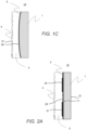
FIG. 1C illustrates a cross-section of a diffuser according to another aspect of the invention; -
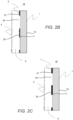
FIG. 2A illustrates a cross-section of a diffuser according to another aspect of the invention; -
FIG. 2B illustrates a cross-section of a diffuser according to another aspect of the invention; -
FIG. 2C illustrates a cross-section of a diffuser according to another aspect of the invention; -
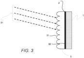
FIG. 3 illustrates a cross-section of a diffuser according to another aspect of the invention; -
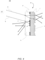
FIG. 4 illustrates a system including a cross-section of a diffuser according to another aspect of the invention; -
FIGs. 5A-5C illustrate a cross-section of a diffuser according to another aspect of the invention; and -
FIG. 6 illustrates a system including a cross-section of a diffuser according to another aspect of the invention. - In an aspect, there is disclosed a diffuser including a substrate having a first surface and a second surface opposite the first surface; a reflective layer; and a refractive layer, in which the refractive layer has an index of refraction n > 1.
- In another aspect, there is disclosed a method of using a system, comprising: receiving illumination, from an illumination source, into a diffuser comprising a substrate having a first surface and a second surface opposite the first surface; a reflective layer; and a refractive layer, wherein the refractive layer has an index of refraction n > 1.
- For simplicity and illustrative purposes, the present disclosure is described by referring mainly to an example thereof. In the following description, numerous specific details are set forth in order to provide a thorough understanding of the present disclosure. It will be readily apparent however, that the present disclosure may be practiced without limitation to these specific details. In other instances, some methods and structures have not been described in detail so as not to unnecessarily obscure the present disclosure.
- Additionally, the elements depicted in the accompanying figures may include additional components and some of the components described in those figures may be removed and/or modified without departing from scopes of the present disclosure. Further, the elements depicted in the figures may not be drawn to scale and thus, the elements may have sizes and/or configurations that differ from those shown in the figures.
- It is to be understood that both the foregoing general description and the following detailed description are exemplary and explanatory only, and are intended to provide an explanation of various embodiments of the present teachings.
- In its broad and varied embodiments, disclosed herein is a
diffuser 10 comprising: asubstrate 1 having afirst surface 11 and asecond surface 12 opposite thefirst surface 11; areflective layer 2; and arefractive layer 3, wherein therefractive layer 3 has an index of refraction n > 1. In an aspect, thereflective layer 2 can be on thefirst surface 11 of thesubstrate 1, and therefractive layer 3 can be on a portion of thereflective layer 2, for example, as shown inFIGs. 1A-4 . In another aspect, thereflective layer 2 can be on thesecond surface 12 of thesubstrate 1, and therefractive layer 3 can be on a portion of thesubstrate 1, as shown inFIGs. 5A-6 . Thediffuser 10 can be a catadioptric diffuser that incorporates a refractive surface that works in conjunction with a reflective surface, either as unpatterned or patterned, to shape an incoming illumination. Thediffuser 10 can combine properties of transmissive and reflective microoptic surfaces allowing for multi-function capabilities in a single component. - As shown in
FIGs. 1A-1C , each of thesubstrate 1,reflective layer 2, andrefractive layer 3 can have a first surface (11, 21, and 31, respectively) and a second surface (12, 22, and 32, respectively) opposite the first surface. In this manner, afirst surface 11 of thesubstrate 1 can interface with thesecond surface 22 of thereflective layer 2, and thefirst surface 21 of thereflective layer 2 can interface with thesecond surface 32 of therefractive layer 3, as shown inFIGs. 1A-4 . Alternatively, asecond surface 12 of thesubstrate 1 can interface with thefirst surface 21 of thereflective layer 2, and thefirst surface 11 of thesubstrate 1 can interface with thesecond surface 32 of therefractive layer 3, as shown inFIGs. 5A-6 . For positional reference, the first surface (11, 21, and 31, respectively) is positioned towards anillumination source 50, and the second surface (12, 22, and 32, respectively) is positioned away from an illumination source. - A
substrate 1 can have afirst surface 11 and asecond surface 12 opposite thefirst surface 11. Thesubstrate 1 can provide support for thediffuser 10. Thesubstrate 1 can be produced in custom dimensions or machines (diced, cored, etc.) from a larger article, such as a larger wafer, glass sheet, glass wafer, or plastic film. In an aspect, thesubstrate 1 can include generally inorganic materials (e.g., a fused silica, a silicon, a germanium, and the like), as monolithic substrates. In another aspect, thesubstrate 1 can be inorganic films coated on a substrate, such as Ta2O5 deposited on a glass substrate. Thesubstrate 1 can be transparent, and can include a transparent material such as glass or plastic to allow a portion of incident illumination to be transmitted unimpeded. In another aspect, thesubstrate 1 can be opaque. - In the
diffuser 10, in an aspect, areflective layer 2 can be present on thefirst surface 11 of thesubstrate 1, as shown inFIGs. 1A-4 . In another aspect, areflective layer 2 can be present on thesecond surface 12 of thesubstrate 1, as shown inFIGs. 5A-6 . Thereflective layer 2 can be formed of highly reflective materials and can include any materials that have reflective characteristics in the desired spectral range. For example, any material with a reflectance ranging from 50% to 100% in the desired spectral range. An example of a reflective material can be aluminum, which has good reflectance characteristics, is inexpensive, and easy to form into or deposit as a thin layer. Other materials can also be used in place of aluminum. For example, copper, silver, gold, platinum, palladium, nickel, cobalt, niobium, chromium, tin, and combinations, blends or alloys of these or other metals can be used as reflective materials. In an aspect, the reflective material can be a white or light colored metal. In other examples, the reflective material can include, but is not limited to, the transition and lanthanide metals and combinations thereof; as well as metal carbides, metal oxides, metal nitrides, metal sulfides, a combination thereof, or mixtures of metals and one or more of these materials. - A reflective material can reflect light in multiple spectral ranges, such as visible light (from about 380 nm to about 800 nm), ultraviolet light (from about 200 nm to about 400 nm), and infrared light (from about 800 nm to about 1 mm). The infrared wavelength range can include near infrared, short-wave infrared, medium wave infrared, and long wave infrared.
- The
reflective layer 2 can have afirst surface 21 including a plurality of light scattering features that can form a diffuser pattern, as shown inFIG. 1A . As shown inFIG. 5A , thereflective layer 2 can have asecond surface 22 including a plurality of light scattering features that can form a diffuser pattern. The light scattering features can spread incident illumination in space. The plurality of light scattering features can be at least one of microstructures, a grating, an array of microlenses, or the like. As shown inFIGs. 1A and5A , the plurality of light scattering features can be present along an entire length of thefirst surface 21 orsecond surface 22, respectively. The plurality of light scattering features can be present along one or more portions of the length of thefirst surface 21 orsecond surface 22. For example, as shown inFIG. 2A , afirst portion 23 of thereflective layer 2 can include a plurality of light scattering features, and can be devoid of light scattering features along asecond portion 24 of thereflective layer 2. - A
first surface 21, and optionally, asecond surface 22 of thereflective layer 2 can be planar, such as, along a portion or an entire length of thereflective layer 2. InFIG. 1A , thefirst surface 21 includes a plurality of light scattering features along an entire length, and thesecond surface 22 is planar, i.e., is flat and/or smooth. InFIG. 5A , thefirst surface 21 is planar, i.e., is flat and/or smooth, and thesecond surface 22 includes a plurality of light scattering features along an entire length. InFIGs. 1B and5B , both thefirst surface 21 and thesecond surface 22 of thereflective layer 2 are planar. - As shown in
FIGs. 1C and5C , the first andsecond surfaces reflective layer 2 can be curved, such as concave, convex, or a combination of both. For example, a first portion of thereflective layer 2 can be concave, and a second portion of thereflective layer 2 can be convex. Thereflective layer 2 can be curved over a portion of thesubstrate 1. - In an aspect, the
reflective layer 2 can extend along an entire length of thesubstrate 1, or can extend along a portion of the length of thesubstrate 1. For example, as shown inFIG. 2B , thereflective layer 2 can be present in two or more portions (first portion 23 and second portion 24) along a length of thesubstrate 1, and wherein each portion (e.g., first portion 23) ofreflective layer 2 is separated by a void (e.g., second portion 24) of reflective material. As shown inFIG. 2C , thereflective layer 2 includes two or morefirst portions 23 including planar reflective material separated by two or moresecond portions 24 including void areas of reflective material to form a diffraction grating. - The
first surface 21 and/or thesecond surface 22 of thereflective layer 2 can be devoid of a diffuser pattern. In another aspect, thefirst surface 21 and/or thesecond surface 22 of thereflective layer 2 can include or form a diffuser pattern. - The
reflective layer 2 can include one or more of a plurality of light scattering features, a planar surface, and a curved surface along one or more portions of thereflective layer 2, and can optionally include one or more portions with voids of plurality of light scattering features, and reflective material. In an aspect, thefirst surface 21 of thereflective layer 2 can include a surface profile chosen from a periodic microstructure, a random microstructure, symmetric, asymmetric, one-dimensional, and two-dimensional. - The
diffuser 10 also includes arefractive layer 3 that can be present on at least a portion thereflective layer 2, wherein therefractive layer 3 has an index of refraction n > 1. Therefractive layer 3 can be formed of any material having an index of refraction n > 1. Therefractive layer 3 can have a degree of transparency to input illumination. - In an aspect, the
refractive layer 3 can encapsulate and/or extend along an entire length of thereflective layer 2. As discussed above, therefractive layer 3 can have afirst surface 31; and asecond surface 32, opposite thefirst surface 31, which interfaces with thereflective layer 2. As shown inFIGs. 1A and 1B , thesecond surface 32 of therefractive layer 3 can interface with thefirst surface 21 of thereflective layer 2, wherein thesecond surface 32 of therefractive layer 3 is planar. As shown inFIG. 1C , thesecond surface 32 of therefractive layer 3 is curved, such as concave, convex, or combinations thereof. Thefirst surface 31 can include adiffuser pattern 4. Therefractive diffuser pattern 4 can be a same or different pattern from a reflective layer diffuser pattern. - The
first surface 31 of therefractive layer 3 can be planar, curved (concave, convex), or combinations thereof, such as along an entire length of thefirst surface 31, or in different portions along the length. Thefirst surface 31 can include a grating pattern. - In another aspect, in portions of the
diffuser 10 that are void of reflective material, therefractive layer 3 can be present on one or more portions of thesubstrate 1, as shown inFIGs. 2B and 2C . For example, a first portion of therefractive layer 3 can extend along the entirereflective layer 2, and wherein a second portion ofrefractive layer 3 can extend along a portion of thesubstrate 1. In an aspect, therefractive layer 3 can be present on a portion of thereflective layer 2. - Additionally, the
refractive layer 3 can be present on afirst surface 11 of thesubstrate 1, for example, when thereflective layer 2 is present on asecond surface 12 of thesubstrate 1, as shown inFIGs. 5A-6 . - In an aspect, the
first surface 31 of therefractive layer 3 can include a grating, a microlens array, or a periodic structure. Thefirst surface 31 can be illuminated byinput beam 51, for example, from alight source 50. Thefirst surface 31 can include a surface profile chosen from general, symmetric, asymmetric, one-dimensional, and two-dimensional. Thefirst surface 31 can be planar or curved. -
FIG. 4 illustrates asystem 100 including anillumination source 50, and adiffuser 10. Thediffuser 10 has been described above. Additionally, thediffuser 10 can include asubstrate 1 with asecond surface 12 including a patternedoptical material 7. The patternedoptical material 7 can extend along an entire length of thesecond surface 12 of thesubstrate 1. In an aspect, the patternedoptical material 7 can be present in a first portion and can be void in a second portion. Theoptical material 7 can be formed from polymeric materials that can be replicated ontosubstrate 1, such as free-radical cure acrylates, cationic cure epoxies, UV cross-linkable polymers, and heat cross-linkable polymers. Alternatively,optical material 7 can be monolithically part of thesubstrate 1 itself, and can be produced via processes such as reactive-ion etching (in the case of hard materials, such as a fused silica, silicon, and germanium) or direct molding (in the case of glass molding or plastic molding via injection-molding or embossing processes). -
FIG. 6 illustrates asystem 100 including anillumination source 50, and adiffuser 10. Thediffuser 10 has been described above. Theillumination source 50 can emit aninput beam 51 that can be received by apattern 4 of thefirst surface 31 of therefractive layer 3. The receivedinput beam 51 can be transmitted through therefractive layer 3 and thesubstrate 1 into thereflective layer 2 on thesecond surface 12 of thesubstrate 1. The transmittedinput beam 51 can be reflected by the plurality of light scattering centers on thesecond surface 22 of thereflective layer 2 into thediffuser 10. - The
system 100 can be used in a method including receiving illumination, from anillumination source 50, into adiffuser 10 comprising asubstrate 1 having afirst surface 31 and asecond surface 32 opposite thefirst surface 31; areflective layer 2 on thefirst surface 31; and arefractive layer 3 on a portion of thereflective layer 2, wherein therefractive layer 3 has an index of refraction n > 1. A portion of the illumination from the light source can be transmitted by therefractive layer 3 to thereflective layer 2; and wherein the transmitted illumination is reflected by thereflective layer 2 back through therefractive layer 3, such as alongray 5 ofFIG. 4 . A portion of the illumination is transmitted by therefractive layer 3 toward thesubstrate 1 and is unimpeded through thediffuser 10, such as alongray 6 ofFIG. 4 . - From the foregoing description, those skilled in the art can appreciate that the present teachings can be implemented in a variety of forms. Therefore, while these teachings have been described in connection with particular embodiments and examples thereof, the true scope of the present teachings should not be so limited. Various changes and modifications can be made without departing from the scope of the teachings herein.
- A set of preferred embodiments is provided below.
- In a first embodiment, a diffuser is provided, the diffuser comprising:
- a substrate having a first surface and a second surface opposite the first surface;
- a reflective layer; and
- a refractive layer, wherein the refractive layer has an index of refraction n > 1.
- The diffuser of the first embodiment, wherein the reflective layer includes a plurality of light scattering features.
- The diffuser of the first embodiment, wherein the plurality of light scattering features is chosen from microstructures, a grating, and an array of microlenses.
- The diffuser of the first embodiment, wherein the reflective layer is planar.
- The diffuser of the first embodiment, wherein the reflective layer is curved.
- The diffuser of the first embodiment, wherein the reflective layer extends along an entire length of the substrate.
- The diffuser of the first embodiment, wherein the reflective layer is present in two or more portions along a length of the substrate, and wherein each portion of reflective layer is separated by a void of reflective material.
- The diffuser of the first embodiment, wherein a second surface of the refractive layer interfaces with a first surface of the reflective layer, wherein the second surface of the refractive layer is planar.
- The diffuser of the first embodiment, wherein a second surface of the refractive layer interfaces with a first surface of the reflective layer, wherein the second surface of the refractive layer is curved.
- The diffuser of the first embodiment, wherein the refractive layer includes a first surface and a second surface, which is opposite the first surface;
- wherein the second surface interfaces with the reflective layer; and
- wherein the first surface includes a diffuser pattern.
- The diffuser of the first embodiment, wherein the refractive layer includes a first surface and a second surface, which is opposite the first surface;
- wherein the second surface interfaces with the reflective layer; and
- wherein the first surface includes a diffuser pattern.
- wherein the reflective layer includes a diffuser pattern; and the refractive layer diffuser pattern is different from the reflective layer diffuser pattern.
- The diffuser of the first embodiment, wherein the refractive layer extends along an entire length of the reflective layer.
- The diffuser of the first embodiment, wherein a first portion of the refractive layer extends along all the reflective layer, and wherein a second portion of refractive layer extends along a portion of the substrate.
- The diffuser of the first embodiment, wherein a portion of the refractive layer interfaces with a portion of the substrate.
- The diffuser of the first embodiment, wherein the second surface of the substrate includes a patterned optical material.
- The diffuser of the first embodiment, wherein a first surface of the refractive layer includes a grating, a microlens array, or a periodic structure.
- A system comprising:
- an illumination source; and
- the diffuser of the first embodiment.
- In a second embodiment, a method of using a system is provided, the method comprising:
- receiving illumination, from an illumination source, into a diffuser comprising a substrate having a first surface and a second surface opposite the first surface;
- a reflective layer; and
- a refractive layer, wherein the refractive layer has an index of refraction n > 1.
- The method of the second embodiment, wherein a portion of the illumination is transmitted by the refractive layer to the reflective layer; and wherein the transmitted illumination is reflected by the reflective layer back through the refractive layer.
- The method of the second embodiment, wherein a portion of the illumination is transmitted by the refractive layer toward the substrate and is unimpeded through the diffuser.
- This scope disclosure is to be broadly construed. It is intended that this disclosure disclose equivalents, means, systems and methods to achieve the devices, activities and mechanical actions disclosed herein. For each device, article, method, mean, mechanical element or mechanism disclosed, it is intended that this disclosure also encompass in its disclosure and teaches equivalents, means, systems and methods for practicing the many aspects, mechanisms and devices disclosed herein. The claims of this application are likewise to be broadly construed. The description of the inventions herein in their many embodiments is merely exemplary in nature and, thus, variations that do not depart from the gist of the invention are intended to be within the scope of the invention. Such variations are not to be regarded as a departure from the spirit and scope of the invention.
Claims (15)
- A diffuser comprising:a substrate having a first surface and a second surface opposite the first surface;a reflective layer; anda refractive layer, wherein the refractive layer has an index of refraction n > 1.
- The diffuser of claim 1, wherein the reflective layer includes a plurality of light scattering features, wherein the plurality of light scattering features is chosen from microstructures, a grating, and an array of microlenses.
- The diffuser of claim 1, wherein the reflective layer is planar or curved.
- The diffuser of claim 1, wherein the reflective layer extends along an entire length of the substrate or wherein the reflective layer extends along an entire length of the reflective layer.
- The diffuser of claim 1, wherein the reflective layer is present in two or more portions along a length of the substrate, and wherein each portion of reflective layer is separated by a void of reflective material.
- The diffuser of claim 1, wherein a second surface of the refractive layer interfaces with a first surface of the reflective layer, wherein the second surface of the refractive layer is planar; orwherein a second surface of the refractive layer interfaces with a first surface of the reflective layer, wherein the second surface of the refractive layer is curved; orwherein a first surface of the refractive layer includes a grating, a microlens array, or a periodic structure.
- The diffuser of claim 1, wherein the refractive layer includes a first surface and a second surface, which is opposite the first surface;wherein the second surface interfaces with the reflective layer; andwherein the first surface includes a diffuser pattern.
- The diffuser of claim 7, wherein the reflective layer includes a diffuser pattern; and the refractive layer diffuser pattern is different from the reflective layer diffuser pattern.
- The diffuser of claim 1, wherein a first portion of the refractive layer extends along all the reflective layer, and wherein a second portion of refractive layer extends along a portion of the substrate.
- The diffuser of claim 1, wherein a portion of the refractive layer interfaces with a portion of the substrate.
- The diffuser of claim 1, wherein the second surface of the substrate includes a patterned optical material.
- A system comprising:an illumination source; andthe diffuser of claim 1.
- A method of using a system, comprising:receiving illumination, from an illumination source, into a diffuser comprising a substrate having a first surface and a second surface opposite the first surface;a reflective layer; anda refractive layer, wherein the refractive layer has an index of refraction n > 1.
- The method of claim 13, wherein a portion of the illumination is transmitted by the refractive layer to the reflective layer; and wherein the transmitted illumination is reflected by the reflective layer back through the refractive layer.
- The method of claim 13, wherein a portion of the illumination is transmitted by the refractive layer toward the substrate and is unimpeded through the diffuser.
Applications Claiming Priority (1)
| Application Number | Priority Date | Filing Date | Title |
|---|---|---|---|
| US18/072,101 US12631801B2 (en) | 2022-11-30 | 2022-11-30 | Reflective and refractive diffuser |
Publications (1)
| Publication Number | Publication Date |
|---|---|
| EP4379433A1 true EP4379433A1 (en) | 2024-06-05 |
Family
ID=89029791
Family Applications (1)
| Application Number | Title | Priority Date | Filing Date |
|---|---|---|---|
| EP23213244.9A Pending EP4379433A1 (en) | 2022-11-30 | 2023-11-30 | A reflective and refractive diffuser |
Country Status (5)
| Country | Link |
|---|---|
| US (1) | US12631801B2 (en) |
| EP (1) | EP4379433A1 (en) |
| JP (2) | JP2024079587A (en) |
| KR (1) | KR20240081408A (en) |
| CN (1) | CN118112700A (en) |
Citations (4)
| Publication number | Priority date | Publication date | Assignee | Title |
|---|---|---|---|---|
| US20070196616A1 (en) * | 2004-07-21 | 2007-08-23 | Rolic Ag | Anisotropic optical device and method for making same |
| US8619363B1 (en) * | 2007-11-06 | 2013-12-31 | Fusion Optix, Inc. | Light redirecting element comprising a forward diffracting region and a scattering region |
| US20160116647A1 (en) * | 2014-10-22 | 2016-04-28 | Intel Corporation | Anti-moire pattern diffuser for optical systems |
| US20220228722A1 (en) * | 2019-07-01 | 2022-07-21 | Dai Nippon Printing Co., Ltd. | Diffusion member, stacked body, diffusion member set, led backlight, and displaying apparatus |
Family Cites Families (13)
| Publication number | Priority date | Publication date | Assignee | Title |
|---|---|---|---|---|
| KR970002673B1 (en) * | 1991-06-03 | 1997-03-07 | 다이닛뽕 인사쓰 가부시기가이샤 | Reflection type projection screen, production process thereof,and production apparatus thereof |
| US6724529B2 (en) * | 2002-04-17 | 2004-04-20 | Howard Sinkoff | Reflection-type projection screens |
| US6898012B2 (en) | 2002-05-16 | 2005-05-24 | Eastman Kodak Company | Light reflector with variable diffuse light reflection |
| JP4747626B2 (en) * | 2005-03-25 | 2011-08-17 | セイコーエプソン株式会社 | Light emitting device |
| US7324276B2 (en) * | 2005-07-12 | 2008-01-29 | Bright View Technologies, Inc. | Front projection screens including reflecting and refractive layers of differing spatial frequencies |
| KR100751519B1 (en) * | 2006-05-08 | 2007-08-23 | 미래나노텍(주) | Back light assembly of the liquid crystal display device provided with the optical sheet and the optical sheet |
| WO2013065172A1 (en) * | 2011-11-04 | 2013-05-10 | パイオニア株式会社 | Light-emitting device and method for producing light-emitting device |
| TW201426111A (en) * | 2012-12-17 | 2014-07-01 | Hon Hai Prec Ind Co Ltd | Backlight module |
| US20150176977A1 (en) * | 2013-12-20 | 2015-06-25 | Lemoptix Sa | Methods and devices for determining position or distance |
| JP6863505B2 (en) | 2019-07-01 | 2021-04-21 | 大日本印刷株式会社 | Diffusing member, laminate, set of diffusing member, LED backlight and display device |
| CN115167069A (en) | 2022-05-26 | 2022-10-11 | 成都菲斯特科技有限公司 | Projection screen and projection system |
| CN114995042B (en) | 2022-05-26 | 2023-11-03 | 成都菲斯特科技有限公司 | Projection screen and projection system |
| CN114995041A (en) | 2022-05-26 | 2022-09-02 | 成都菲斯特科技有限公司 | Projection screen and projection system |
-
2022
- 2022-11-30 US US18/072,101 patent/US12631801B2/en active Active
-
2023
- 2023-10-26 JP JP2023183808A patent/JP2024079587A/en active Pending
- 2023-11-27 CN CN202311592744.2A patent/CN118112700A/en active Pending
- 2023-11-28 KR KR1020230168674A patent/KR20240081408A/en active Pending
- 2023-11-30 EP EP23213244.9A patent/EP4379433A1/en active Pending
-
2025
- 2025-10-23 JP JP2025178189A patent/JP2026012836A/en active Pending
Patent Citations (4)
| Publication number | Priority date | Publication date | Assignee | Title |
|---|---|---|---|---|
| US20070196616A1 (en) * | 2004-07-21 | 2007-08-23 | Rolic Ag | Anisotropic optical device and method for making same |
| US8619363B1 (en) * | 2007-11-06 | 2013-12-31 | Fusion Optix, Inc. | Light redirecting element comprising a forward diffracting region and a scattering region |
| US20160116647A1 (en) * | 2014-10-22 | 2016-04-28 | Intel Corporation | Anti-moire pattern diffuser for optical systems |
| US20220228722A1 (en) * | 2019-07-01 | 2022-07-21 | Dai Nippon Printing Co., Ltd. | Diffusion member, stacked body, diffusion member set, led backlight, and displaying apparatus |
Also Published As
| Publication number | Publication date |
|---|---|
| JP2024079587A (en) | 2024-06-11 |
| US12631801B2 (en) | 2026-05-19 |
| JP2026012836A (en) | 2026-01-27 |
| KR20240081408A (en) | 2024-06-07 |
| US20240176052A1 (en) | 2024-05-30 |
| CN118112700A (en) | 2024-05-31 |
Similar Documents
| Publication | Publication Date | Title |
|---|---|---|
| US10330844B1 (en) | Backlight unit and display device | |
| US8641257B2 (en) | Optic system for light guide with controlled output | |
| US7113336B2 (en) | Microlens including wire-grid polarizer and methods of manufacture | |
| CN108508509B (en) | A kind of peep-proof film and preparation method thereof, backlight module, display device | |
| US7760445B2 (en) | Compound lens and compound lens array | |
| WO2013163933A1 (en) | Light guide plate with concave microstructure and manufacturing method thereof | |
| US20040156130A1 (en) | Homogenizing optical sheet, method of manufacture, and illumination system | |
| EP2202555B1 (en) | Collimate lens assembly | |
| CN108885311B (en) | Wavelength Division Multiplexer/Demultiplexer with Optical Adjustment Flexibility | |
| KR102242153B1 (en) | Polymeric multilayer optical film | |
| JP2023536923A (en) | LIGHT-INCOUPLING DEVICES, RELATED METHODS AND USES | |
| KR20060133484A (en) | Lighting device, display device, optical sheet and manufacturing method thereof | |
| US20130335827A1 (en) | Optics arrangement and method for optical sampling of an object plane comprising a multi-channel imaging system | |
| WO2013067846A1 (en) | Optical wavelength dispersion device and method of manufacturing the same | |
| KR20230043875A (en) | Optical Incoupling Tapes, Related Methods and Applications | |
| CN101074997B (en) | Anti-reflection structure and optical device including same | |
| KR20190085968A (en) | Microstructured light guide plate and apparatus including the same | |
| WO2010077367A2 (en) | Optic system for light guide with controlled output | |
| US9958601B2 (en) | Display backlight | |
| US12631801B2 (en) | Reflective and refractive diffuser | |
| KR100702287B1 (en) | Apparatus comprising an optical element with an integrated surface diffuser | |
| CN1885129B (en) | Lighting devices and display devices | |
| JP2011257678A (en) | Wire grid polarizing plate and liquid crystal display device using the wire grid polarizing plate | |
| JP2011511315A (en) | Thin film beam splitter based on MEMS | |
| HK40104778A (en) | A reflective and refractive diffuser |
Legal Events
| Date | Code | Title | Description |
|---|---|---|---|
| PUAI | Public reference made under article 153(3) epc to a published international application that has entered the european phase |
Free format text: ORIGINAL CODE: 0009012 |
|
| STAA | Information on the status of an ep patent application or granted ep patent |
Free format text: STATUS: THE APPLICATION HAS BEEN PUBLISHED |
|
| AK | Designated contracting states |
Kind code of ref document: A1 Designated state(s): AL AT BE BG CH CY CZ DE DK EE ES FI FR GB GR HR HU IE IS IT LI LT LU LV MC ME MK MT NL NO PL PT RO RS SE SI SK SM TR |
|
| STAA | Information on the status of an ep patent application or granted ep patent |
Free format text: STATUS: REQUEST FOR EXAMINATION WAS MADE |
|
| 17P | Request for examination filed |
Effective date: 20241204 |
|
| RBV | Designated contracting states (corrected) |
Designated state(s): AL AT BE BG CH CY CZ DE DK EE ES FI FR GB GR HR HU IE IS IT LI LT LU LV MC ME MK MT NL NO PL PT RO RS SE SI SK SM TR |