EP4379368A1 - Sample support unit, and sample ionization method - Google Patents
Sample support unit, and sample ionization method Download PDFInfo
- Publication number
- EP4379368A1 EP4379368A1 EP22910465.8A EP22910465A EP4379368A1 EP 4379368 A1 EP4379368 A1 EP 4379368A1 EP 22910465 A EP22910465 A EP 22910465A EP 4379368 A1 EP4379368 A1 EP 4379368A1
- Authority
- EP
- European Patent Office
- Prior art keywords
- substrate
- sample
- support unit
- sample support
- frame
- Prior art date
- Legal status (The legal status is an assumption and is not a legal conclusion. Google has not performed a legal analysis and makes no representation as to the accuracy of the status listed.)
- Withdrawn
Links
Images





Classifications
-
- H—ELECTRICITY
- H01—ELECTRIC ELEMENTS
- H01J—ELECTRIC DISCHARGE TUBES OR DISCHARGE LAMPS
- H01J49/00—Particle spectrometers or separator tubes
- H01J49/02—Details
- H01J49/04—Arrangements for introducing or extracting samples to be analysed, e.g. vacuum locks; Arrangements for external adjustment of electron- or ion-optical components
-
- G—PHYSICS
- G01—MEASURING; TESTING
- G01N—INVESTIGATING OR ANALYSING MATERIALS BY DETERMINING THEIR CHEMICAL OR PHYSICAL PROPERTIES
- G01N1/00—Sampling; Preparing specimens for investigation
- G01N1/28—Preparing specimens for investigation including physical details of (bio-)chemical methods covered elsewhere, e.g. G01N33/50, C12Q
- G01N1/40—Concentrating samples
-
- G—PHYSICS
- G01—MEASURING; TESTING
- G01N—INVESTIGATING OR ANALYSING MATERIALS BY DETERMINING THEIR CHEMICAL OR PHYSICAL PROPERTIES
- G01N27/00—Investigating or analysing materials by the use of electric, electrochemical, or magnetic means
- G01N27/62—Investigating or analysing materials by the use of electric, electrochemical, or magnetic means by investigating the ionisation of gases, e.g. aerosols; by investigating electric discharges, e.g. emission of cathode
-
- G—PHYSICS
- G01—MEASURING; TESTING
- G01N—INVESTIGATING OR ANALYSING MATERIALS BY DETERMINING THEIR CHEMICAL OR PHYSICAL PROPERTIES
- G01N27/00—Investigating or analysing materials by the use of electric, electrochemical, or magnetic means
- G01N27/62—Investigating or analysing materials by the use of electric, electrochemical, or magnetic means by investigating the ionisation of gases, e.g. aerosols; by investigating electric discharges, e.g. emission of cathode
- G01N27/622—Ion mobility spectrometry
- G01N27/623—Ion mobility spectrometry combined with mass spectrometry
-
- H—ELECTRICITY
- H01—ELECTRIC ELEMENTS
- H01J—ELECTRIC DISCHARGE TUBES OR DISCHARGE LAMPS
- H01J49/00—Particle spectrometers or separator tubes
- H01J49/02—Details
- H01J49/04—Arrangements for introducing or extracting samples to be analysed, e.g. vacuum locks; Arrangements for external adjustment of electron- or ion-optical components
- H01J49/0409—Sample holders or containers
- H01J49/0418—Sample holders or containers for laser desorption, e.g. matrix-assisted laser desorption/ionisation [MALDI] plates or surface enhanced laser desorption/ionisation [SELDI] plates
-
- H—ELECTRICITY
- H01—ELECTRIC ELEMENTS
- H01J—ELECTRIC DISCHARGE TUBES OR DISCHARGE LAMPS
- H01J49/00—Particle spectrometers or separator tubes
- H01J49/02—Details
- H01J49/10—Ion sources; Ion guns
- H01J49/16—Ion sources; Ion guns using surface ionisation, e.g. field-, thermionic- or photo-emission
-
- G—PHYSICS
- G01—MEASURING; TESTING
- G01N—INVESTIGATING OR ANALYSING MATERIALS BY DETERMINING THEIR CHEMICAL OR PHYSICAL PROPERTIES
- G01N1/00—Sampling; Preparing specimens for investigation
- G01N1/28—Preparing specimens for investigation including physical details of (bio-)chemical methods covered elsewhere, e.g. G01N33/50, C12Q
- G01N1/40—Concentrating samples
- G01N2001/4038—Concentrating samples electric methods, e.g. electromigration, electrophoresis, ionisation
Definitions
- One aspect of the present disclosure relates to a sample support unit and a sample ionization method.
- Patent Literature 1 a sample support used for the ionization of a sample such as a biological sample in sample mass analysis is described.
- the sample support described in Patent Literature 1 includes a substrate having a porous structure formed to communicate a first surface and a second surface facing each other.
- the components of the sample are moved toward the first surface side from the second surface side of the substrate via the porous structure, and the components of the sample are supplied to the first surface side.
- the first surface is irradiated with laser light to ionize the components of the sample.
- Patent Literature 1 International Publication WO 2019/155741
- the edge portion of the substrate is interposed between clamping portions of a holder to fix the sample support.
- the pressing force of the clamping portions of the holder may be set to be strong in order to suppress the misregistration of the sample support during measurement. Accordingly, there is a possibility that the substrate is bent by the pressing force from the clamping portions. In a case where the substrate is bent, there is a concern that a deviation occurs in a measurement result, or the substrate is damaged.
- An object of one aspect of the present disclosure is to provide a sample support unit and a sample ionization method capable of suppressing the bending of a substrate during fixation.
- a sample support unit is a sample support unit used for ionization of a sample, the unit including: a substrate including a first surface, and a second surface on a side opposite to the first surface, and including a porous structure formed therein and opened to at least the first surface; and a frame removably attached to the substrate and retaining the substrate such that at least a part of the first surface is exposed, in which the frame includes a fixing portion positioned outside the substrate when viewed in a direction perpendicular to the first surface, in a state of being attached to the substrate.
- Such a sample support unit includes the frame that is removably attached to the substrate, and retains the substrate such that at least a part of the first surface is exposed, and the frame includes the fixing portion positioned outside the substrate when viewed in the direction perpendicular to the first surface, in the state of being attached to the substrate. Accordingly, it is possible to fix the sample support unit by interposing the fixing portion between clamping portions of a holder. In this case, since it is possible for the frame to receive a pressing force from the clamping portions, it is possible to suppress the bending of the substrate due to the pressing force from the clamping portions, without depending on the strength of the substrate. As described above, according to such a sample support unit, it is possible to suppress the bending of the substrate during fixation.
- the fixing portion may include a surface positioned on the same plane as that of the first surface. In this case, when fixing the sample support unit by interposing the fixing portion between the clamping portions of the holder, it is possible to position a measurement surface of the holder and the first surface of the substrate on the same plane, and accurately perform measurement.
- the frame may include a first member disposed on a side of the first surface, and a second member disposed on a side of the second surface. In this case, it is possible to reliably retain the substrate with the first member and the second member.
- the fixing portion may be formed by an overlapping portion of the first member and the second member. In this case, it is possible to increase the strength of the fixing portion, and further suppress the bending of the substrate during fixation.
- the first member may be formed in a frame shape. In this case, it is possible to reliably retain the substrate.
- the second member may be formed in a plate shape such that the frame covers an entirety of the second surface in a state of being attached to the substrate. In this case, it is possible to reliably retain the substrate.
- the second member may be formed in a frame shape. In this case, it is possible to visually check the state of the substrate from the side of the second surface.
- the first member and the second member may be formed such that the substrate is interposed between the first member and the second member in a state in which the frame is attached to the substrate. In this case, it is possible to reliably retain the substrate.
- the frame may include a first member disposed on a side of the first surface side, and the first member may be provided with a claw portion engaged with the second surface. In this case, it is possible to retain the substrate by engaging the claw portion with the second surface.
- the frame may be formed with a calibration region used for mass calibration and the calibration region may be visually identifiable from a region adjacent to the calibration region, and a surface of the calibration region may be positioned on the same plane as that of the first surface.
- the calibration region may be visually identifiable from a region adjacent to the calibration region, and a surface of the calibration region may be positioned on the same plane as that of the first surface.
- the porous structure may be formed of a sintered body of glass beads, porous glass, a fiber porous body, anodically oxidized silicon, an anodically oxidized valve metal, porous ceramic, or a porous metal. In this case, it is possible to preferably configure the porous structure.
- a sample ionization method is a sample ionization method using the sample support unit described above, the method including: a supplying step of supplying components of the sample to the first surface; a fixing step of fixing the sample support unit by interposing the fixing portion of the frame between clamping portions of a holder; and an ionizing step of ionizing the components of the sample on the first surface after the supplying step and the fixing step.
- the sample support unit in the fixing step, is fixed by interposing the fixing portion of the frame between the clamping portions of the holder. Accordingly, since it is possible for the frame to receive a pressing force from the clamping portions, it is possible to suppress the bending of the substrate due to the pressing force from the clamping portions, without depending on the strength of the substrate. As described above, according to such a sample ionization method, it is possible to suppress the bending of the substrate during fixation.
- the sample support unit may be fixed such that a surface of the holder and the first surface are positioned on the same plane. In this case, it is possible to position the surface (the measurement surface) of the holder and the first surface on the same plane, and accurately perform the measurement.
- the sample support unit and the sample ionization method capable of suppressing the bending of the substrate during fixation.
- a sample support unit 1 illustrated in FIG. 1 to FIG. 5 is used to ionize the components of a sample, which is a measurement target, in mass analysis.
- the sample for example, is a biological sample or the like.
- the sample support unit 1 includes a substrate 2 and a frame 3.
- the substrate 2 for example, is formed of an insulating material in a rectangular plate shape, and has a first surface 2a, and a second surface 2b on a side opposite to the first surface 2a.
- the first surface 2a and the second surface 2b are the main surface of the substrate 2, and for example, a flat surface perpendicular to a thickness direction of the substrate 2.
- the length of one side of the substrate 2 when viewed in the thickness direction of the substrate 2, for example, is approximately several cm, and the thickness of the substrate 2, for example, is approximately 1 ⁇ m to 1000 ⁇ m.
- the thickness direction of the substrate 2 (a direction perpendicular to the first surface 2a) will be described as a Z direction
- a direction perpendicular to the Z direction will be described as an X direction
- a direction perpendicular to the Z direction and the X direction will be described as a Y direction.
- the X direction is a direction parallel to the long side of the substrate 2.
- a porous structure communicating the first surface 2a and the second surface 2b with each other is formed.
- the porous structure has a structure in which voids (air gaps) (pores) extend in an irregular direction and are irregularly distributed in three dimensions (an irregular porous structure).
- the voids in the porous structure form through holes opened to the first surface 2a and the second surface 2b.
- the irregular porous structure for example, is a sponge-shaped structure.
- the porous structure is formed over the entire first surface 2a, but the porous structure may be formed in a part of the first surface 2a.
- the substrate 2 is formed of a sintered body of glass beads.
- the sintered body of the glass beads for example, has a structure in which a plurality of glass beads are integrated by sintering.
- the shape of each of the glass beads for example, is a spherical shape.
- the shapes and the sizes of the glass beads contained in the substrate 2 may be even, or may be uneven.
- the porous structure described above is formed of the plurality of glass beads and a plurality of voids formed between the glass beads.
- the voids between the glass beads are irregularly communicated with each other.
- the average particle size (diameter) of the glass beads for example, is approximately 50 ⁇ m.
- the porosity of the porous structure for example, is 40% to 50%.
- the first surface 2a of the substrate 2 has electrical conductivity.
- a conductive layer is formed on the first surface 2a.
- the conductive layer covers the entire first surface 2a except for the opening portion of the porous structure.
- the conductive layer for example, is formed of a metal material such as Pt.
- the frame 3 is a member that is removably attached to the substrate 2, and retains the substrate 2 such that a part of the first surface 2a is exposed.
- the frame 3 is a member different from the substrate 2, which is independent from the substrate 2.
- the frame 3 is formed of a metal material having electrical conductivity, and has high rigidity. Examples of the material of the frame 3 include stainless steel (SUS), aluminum, a ferrous alloy, and the like.
- the frame 3 includes a first member 10 disposed on the first surface 2a side, and a second member 20 disposed on the second surface 2b side.
- the first member 10 is formed in a rectangular frame shape, and defines a rectangular opening 10a.
- the long side of the opening 10a extends along the long side of the substrate 2 (along the X direction).
- the opening 10a is formed in a rectangular shape slightly smaller than the substrate 2 when viewed in the Z direction. In a state where the frame 3 is attached to the substrate 2 ( FIG. 1 ), a part (the center portion) of the first surface 2a is exposed from the opening 10a.
- the first member 10 includes a main body portion 11 formed in a rectangular frame shape, and a holding portion 12 provided on one side of the main body portion 11 in the Z direction.
- the entire main body portion 11 is positioned outside the substrate 2 when viewed in the Z direction.
- the main body portion 11 defines a rectangular opening 11a.
- the long side of the opening 11a extends along the long side of the substrate 2 (along the X direction).
- the opening 11a is formed in a shape corresponding to the substrate 2 (a rectangular shape) when viewed in the Z direction, and the substrate 2 is tightly disposed in the opening 11a.
- the holding portion 12 is formed on a surface 11b of the main body portion 11, and has a rectangular frame shape in which the length in the X direction is shorter than that of the main body portion 11.
- the holding portion 12 protrudes toward the center side of the frame 3 from the main body portion 11, and a step is formed between the holding portion 12 and the main body portion 11.
- the opening 10a described above is defined by the holding portion 12.
- the thickness of the holding portion 12, for example, is approximately 1 mm.
- the second member 20 is formed in a rectangular plate shape corresponding to the first member 10.
- the second member 20 covers the entire second surface 2b, in a state where the frame 3 is attached to the substrate 2 ( FIG. 1 ).
- the frame 3 includes a fixing portion 31 formed by an overlapping portion of the first member 10 and the second member 20.
- the entire fixing portion 31 is positioned outside the substrate 2 (outside the outer edge of the substrate 2) when viewed in the Z direction.
- the fixing portion 31 is hatched.
- the fixing portion 31 is provided in each of one end portion and the other end portion of the frame 3 in the X direction, and each of the fixing portions 31 is formed in a rectangular shape having a long side parallel to the Y direction.
- Each of the fixing portions 31 has a surface 31a positioned on the same plane as that of the first surface 2a.
- the surface 31a is formed by the surface 11b of the main body portion 11 of the first member 10. That is, the surface 11b of the main body portion 11 is positioned on the same plane as that of the first surface 2a.
- the thickness of the fixing portion 31, for example, is approximately 1.5 mm.
- the frame 3 is attached to the substrate 2 to retain the substrate 2.
- the substrate 2 is interposed and fixed between the holding portion 12 and the second member 20.
- a part (the center portion) of the first surface 2a is exposed from the opening 10a.
- detachment for example, it is possible to detach the frame 3 from the substrate 2 by separating the first member 10 from the second member 20, and then, taking out the substrate 2.
- the sample support unit 1 is fixed by a holder 100.
- the holder 100 includes a holder main body 101, and a plurality of (in this example, four) clamping portions 102.
- the holder main body 101 for example, is formed in a rectangular frame shape.
- Each of the clamping portions 102 for example, is configured by including a contact member 103 and a biasing member 104.
- the contact member 103 is fixed to a surface 101a of the holder main body 101.
- the contact member 103 is disposed to protrude toward the center side of the holder main body 101 from the holder main body 101.
- the biasing member 104 is disposed to face the contact member 103 in the Z direction.
- the biasing member 104 for example, is configured by including a spring, and capable of biasing the sample support unit 1 disposed between the biasing member 104 and the contact member 103 toward the contact member 103.
- two clamping portions 102 among four clamping portions 102 are disposed on one side in the X direction and arranged in the Y direction, and the rest two clamping portions 102 are disposed on the other side in the X direction and arranged in the Y direction.
- FIG. 5 the sample support unit 1 before being fixed by the holder 100 is illustrated.
- the first member 10 and the second member 20 are not in contact with each other. That is, in this example, a gap D between the holding portion 12 of the first member 10 and the second member 20 is larger than the thickness of the substrate 2.
- the gap D is approximately 0.5 mm larger than the thickness of the substrate 2.
- FIG. 4 a state where the sample support unit 1 is fixed by the holder 100 is illustrated.
- the sample support unit 1 is fixed.
- the first member 10 and the second member 20 are brought into contact with each other by the pressing force of the clamping portions 102, and the substrate 2 is interposed and fixed between the holding portion 12 of the first member 10 and the second member 20. That is, the first member 10 and the second member 20 are formed such that the substrate 2 is interposed between the first member 10 and the second member 20 in the fixed state.
- the fixing portion 31 of the frame 3 is interposed between the clamping portions 102, but the substrate 2 is not interposed between the clamping portions 102.
- the contact member 103 of the clamping portion 102 is in contact with the surface 31a of the fixing portion 31, and the biasing member 104 is in contact with the second member 20.
- the contact member 103 is provided on the surface 101a of the holder main body 101 to extend in a direction perpendicular to the Z direction.
- the surface 31a of the fixing portion 31 is positioned on the same plane as that of the first surface 2a of the substrate 2. Accordingly, the surface 101a of the holder main body 101 and the first surface 2a of the substrate 2 are positioned on the same plane.
- the surface 101a of the holder main body 101 functions as a measurement surface in mass analysis measurement. Accordingly, by positioning the surface 101a and the first surface 2a (the effective surface of the substrate 2) on the same plane, it is possible to accurately perform the measurement.
- Such a mass analysis method includes a step of ionizing a sample by using the sample support unit 1 (an ionization method), and a step of detecting the ions.
- an ionization method includes a step of ionizing a sample by using the sample support unit 1 (an ionization method), and a step of detecting the ions.
- the components of a sample S are supplied to the first surface 2a of the substrate 2 (a supplying step).
- the sample S is placed on the first surface 2a of the substrate 2 ( FIG. 6(a) ).
- the sample S is pressed toward the substrate 2 side, and the sample S is closely attached to the first surface 2a of the substrate 2 ( FIG. 6(b) ).
- the components of the sample S are infiltrated and absorbed into the substrate 2 ( FIG. 7(a) ).
- the sample S is removed ( FIG. 7(a) ). According to the steps described above, as illustrated in FIG.
- the substrate 2 retaining the components of the sample S is obtained, and in a state where positional information is stored, the components of the sample S are supplied to the first surface 2a of the substrate 2.
- the plan view of the substrate 2 is illustrated on the upper side, and the sectional view of the substrate 2 is illustrated on the lower side.
- FIG. 7(b) the sectional view of the substrate 2 is illustrated.
- the frame 3 is attached to the substrate 2 (an attaching step).
- the sample support unit 1 is fixed (a fixing step).
- the fixing step the sample support unit 1 is fixed such that the surface 101a of the holder main body 101 and the first surface 2a of the substrate 2 are positioned on the same plane by bringing the contact member 103 of the clamping portion 102 into contact with the surface 31a of the fixing portion 31.
- the components of the sample S on the first surface 2a are ionized (an ionizing step). For example, by scanning (irradiating) the first surface 2a with laser light in a state where a voltage is applied to the conductive layer on the first surface 2a, the components of the sample S on the first surface 2a are ionized.
- an ionization method is a laser desorption/ionization method using laser light (an energy line).
- the sample ions discharged from the substrate 2 are detected by an ion detection unit of a mass analysis device (an ion detecting step of the mass analysis method).
- a ground electrode is provided between the substrate 2 and the ion detection unit, and the sample ions are moved toward the ground electrode while being accelerated by a potential difference between the conductive layer and the ground electrode.
- the sample ions are detected by the ion detection unit, and the mass analysis measurement for the sample S is implemented.
- the ion detection unit detects the sample ions, in association with the scanning position of the laser light.
- the mass analysis device for example, is a device performing mass analysis for the sample S by using time-of-flight mass spectrometry (TOF-MS).
- TOF-MS time-of-flight mass spectrometry
- the sample support unit 1 includes the frame 3 that is removably attached to the substrate 2, and retains the substrate 2 such that a part of the first surface 2a is exposed, and the frame 3 includes the fixing portion 31 positioned outside the substrate 2 when viewed in the Z direction (the direction perpendicular to the first surface 2a), in the state of being attached to the substrate 2. Accordingly, by interposing the fixing portion 31 between the clamping portions 102 of the holder 100, it is possible to fix the sample support unit 1. In this case, since it is possible for the frame 3 to receive the pressing force from the clamping portions 102, it is possible to suppress the bending of the substrate 2 due to the pressing force from the clamping portions 102, without depending on the strength of the substrate 2.
- sample support unit 1 As described above, according to such a sample support unit 1, it is possible to suppress the bending of the substrate 2 during fixation.
- the sample support unit 1 for example, even in a case where the shape of the holder 100 is changed, it is sufficient that the shape of the frame 3 is changed in accordance with the change, and it is not necessary to change the design of the substrate 2.
- the frame 3 since the frame 3 is separated from the substrate 2, it is sufficient to replace only the substrate 2, and it is possible to reduce the replacement frequency of the frame 3.
- FIG. 8 In a case where a substrate 55 is interposed and fixed between clamping portions 51 of a holder consisting of a contact member 52 and a biasing member 53, there is a possibility that the substrate 55 is bent by the pressing force from the biasing member 53.
- the substrate 2 since the substrate 2 is fixed by interposing the fixing portion 31 of the frame 3 between the clamping portions 102, without interposing the substrate 2, it is possible to suppress the bending of the substrate 2 during fixation.
- the fixing portion 31 has the surface 31a positioned on the same plane as that of the first surface 2a. Accordingly, when fixing the sample support unit 1 by interposing the fixing portion 31 between the clamping portions 102 of the holder 100, it is possible to position the surface 101a (the measurement surface) of the holder main body 101 of the holder 100 and the first surface 2a of the substrate 2 on the same plane, and accurately perform the measurement.
- the mass analysis device may be designed or optimized such that the surface 101a is the measurement surface (the irradiation point of laser light, the point of origin of time-of-flight analysis), which is because it is considered that a decrease in an ionization efficiency or a shift in flight time occurs due to discordance in the focal range of the laser irradiation in a case where the surface 101a and the first surface 2a are not positioned on the same plane.
- the frame 3 has the first member 10 disposed on the first surface 2a side, and the second member 20 disposed on the second surface 2b side. Accordingly, it is possible to reliably retain the substrate 2 with the first member 10 and the second member 20.
- the fixing portion 31 is composed of the overlapping portion of the first member 10 and the second member 20. Accordingly, it is possible to increase the strength of the fixing portion 31, and further suppress the bending of the substrate 2 during fixation.
- the first member 10 is formed in a frame shape.
- the second member 20 is formed in a plate shape to cover the entire second surface 2b in a state where the frame 3 is attached to the substrate 2. Accordingly, it is possible to reliably retain the substrate 2.
- the first member 10 and the second member 20 are formed such that the substrate 2 is interposed between the first member 10 and the second member 20 in a state where the frame 3 is attached to the substrate 2. Accordingly, it is possible to reliably retain the substrate 2.
- the frame 3 is formed of the metal material having electrical conductivity. Accordingly, it is possible to facilitate the application of a voltage to the first surface 2a when ionizing the sample. In addition, it is possible to increase the strength of the frame 3, and further suppress the bending of the substrate 2 during fixation.
- the porous structure is formed of the sintered body of the glass beads. Accordingly, it is possible to preferably configure the porous structure.
- the sample support unit 1 may be configured as with a first modification example illustrated in FIG. 10 .
- the holding portion 12 is formed to hold the substrate 2 over the entire circumference, but in the first modification example, the holding portion 12 is formed to partially hold the substrate 2.
- the holding portion 12 of the first modification example has four (a plurality of) portions 12a formed in an approximately L shape when viewed in the Z direction. Four portions 12a are disposed in positions corresponding to four corners of the substrate 2, respectively. In this example, a part of the first surface 2a of the substrate 2 is exposed between four portions 12a.
- calibration regions 35 and 36 are formed in the frame 3.
- the calibration regions 35 and 36 are formed on the surface 11b of the main body portion 11.
- the surface 11b of the main body portion 11 is positioned on the same plane as that of the first surface 2a of the substrate 2. That is, the surfaces of the calibration regions 35 and 36 are positioned on the same plane of the first surface 2a.
- Two calibration regions 35 are provided, in which one calibration region 35 is disposed in one side portion of the frame 3 in the X direction, and the other calibration region 35 is disposed in the other side portion of the frame 3 in the X direction.
- Each of the calibration regions 35 for example, is formed in a circular shape.
- Two calibration regions 36 are provided, in which one calibration region 36 is disposed in one side portion of the frame 3 in the Y direction, and the other calibration region 36 is disposed in the other side portion of the frame 3 in the Y direction.
- Each of the calibration regions 36 for example, is formed in a rectangular shape having a long side parallel to the X direction.
- the calibration region 35 is visually identifiable from a region adjacent to the calibration region 35 in the frame 3. That is, regions adjacent to the calibration region 35 and the calibration region 35 can be distinguishable with human eyes.
- a method for making the calibration region 35 identifiable may be any method, and for example, a groove may be formed around the calibration region 35 by half-etching, or a mark may be engraved by laser.
- the calibration region 36 is visually identifiable from the region adjacent to the calibration region 36.
- the calibration regions 35 and 36 are used for mass calibration.
- the mass calibration may be performed before the mass analysis measurement for the sample S is started.
- a sample for mass calibration (a calibration sample, a reference sample) is dropped onto the calibration regions 35 and 36, and the ionization and the mass analysis measurement described above are implemented on the calibration sample.
- Amass spectrum is corrected on the basis of a measurement result for the calibration sample.
- the mass spectrum is a spectrum obtained by the mass analysis, and for example, represented by a graph in which a horizontal axis is set as an m/z value, and a vertical axis is set as a detected strength.
- the m/z value is a mass-charge ratio obtained by dividing the mass m of the ions by the charge number z. Since the mass spectrum of the calibration sample is known, it is possible to perform the mass calibration of the mass analysis device, on the basis of the measurement result for the calibration sample.
- the calibration regions 35 and 36 visually identifiable from the adjacent region are formed in the frame 3. In this case, for example, it is possible to widely ensure a region for measurement on the substrate 2, compared to a case where the calibration region is formed on the substrate 2. In addition, since the surface of the frame 3 in the calibration regions 35 and 36 is positioned on the same plane as that of the first surface 2a of the substrate 2, it is possible to accurately perform the mass calibration.
- the surface of the frame 3 in the calibration regions 35 and 36 is positioned on the same plane as that of the first surface 2a of the substrate 2.
- the sample support unit 1 may be configured as with a second modification example illustrated in FIG. 11(a) .
- the second member 20 is formed in a rectangular frame shape, and defines a rectangular opening 20a.
- the long side of the opening 20a extends along the long side of the substrate 2 (along the X direction).
- the opening 20a is formed in a rectangular shape slightly smaller than the substrate 2 when viewed in the Z direction.
- a part (the center portion) of the second surface 2b is exposed from the opening 20a.
- the second member 20 since the second member 20 is formed in a frame shape, it is possible to visually check the state of the substrate 2 from the second surface 2b side.
- the sample support unit 1 may be configured as with a third modification example illustrated in FIG. 11(b) .
- the frame 3 has only the first member 10 without having the second member 20.
- the fixing portion 31 is formed by the first member 10 only.
- the first member 10 is provided with four claw portions 15 engaged with the second surface 2b of the substrate 2. Two claw portions 15 are disposed in one long side portion of the first member 10, and the other two claw portions 15 are disposed in the other long side portion of the first member 10.
- Each of the claw portions 15 is rotatable around a fixing part with respect to the first member 10 as indicated by an arrow in FIG. 11(b) . As illustrated in FIG.
- the claw portion 15 in a state where the claw portion 15 protrudes from the first member 10, the claw portion 15 is engaged with the second surface 2b of the substrate 2 to prevent the separation of the substrate 2 from the frame 3.
- the substrate 2 can be attached to or detached from the frame 3, in a state where the claw portion is rotated to a position where the claw portion 15 does not protrude from the first member 10.
- the porous structure of the substrate 2 may be formed of porous glass or a fiber porous body.
- the porous glass is a sponge-shaped glass plate in which a plurality of pores are irregularly formed and linked.
- the fiber porous body has a structure (an aggregate) in which a plurality of linear cellulose nanofibers overlap with each other.
- the fiber porous body for example, may have a structure in which a plurality of carbon nanofibers, a plurality of fibrous porous silicas, a plurality of glass fibers, or combinations thereof overlap with each other.
- the porous structure of the substrate 2 may be formed of anodically oxidized silicon or an anodically oxidized valve metal.
- the porous structure has a plurality of through holes formed to communicate the first surface 2a and the second surface 2b of the substrate 2 with each other.
- Such through holes for example, are a plurality of pores extending along the thickness direction of the substrate 2, and in this case, the porous structure has a structure in which the plurality of pores are regularly disposed (a regular porous structure).
- the porous structure is formed of the anodically oxidized valve metal (for example, aluminum (Al))
- the porous structure for example, may be an Al alumina porous film.
- a porous structure can be obtained by performing an anodization treatment with respect to an Al substrate, and peeling off the oxidized surface portion from the Al substrate.
- the porous structure may be formed by anodically oxidizing a valve metal other than Al, such as tantalum (Ta), niobium (Nb), titanium (Ti), hafnium (Hf), zirconium (Zr), zinc (Zn), tungsten (W), bismuth (Bi), and antimony (Sb).
- the porous structure of the substrate 2 may be formed of porous ceramic or a porous metal.
- the structure of the porous ceramic is in a sponge shape in which a plurality of pores are irregularly formed and linked, as with the porous glass.
- the porous metal is a sponge-shaped metal perforated body (may be referred to as a metal porous body, a foam metal, a porous metal, a perforated metal, or the like) in which a plurality of pores are irregularly formed and linked.
- the conductive layer may not be formed on the first surface 2a of the substrate 2, and the first surface 2a may have electrical insulating properties.
- the sample S can be ionized by a desorption electrospray ionization method in which the sample S is desorbed and ionized by irradiating the sample S with electrically charged minute liquid droplets.
- the porous structure formed in the substrate 2 is opened to the first surface 2a and the second surface 2b, but it is sufficient that the porous structure is capable of absorbing the components of the sample S supplied to the first surface 2a, and the porous structure may be opened only to the first surface 2a.
- the components of the sample S are supplied to the first surface 2a by placing the sample S on the first surface 2a of the substrate 2, but instead of this, the sample support unit 1 may be disposed on the sample S such that the second surface 2b is brought into contact with the sample S.
- the components of the sample S are moved toward the first surface 2a side from the second surface 2b side through a plurality of paths (the voids in the porous structure) formed in the substrate 2 by a capillary action.
- the components of the sample S moved to the first surface 2a side remain on the first surface 2a side by a surface tension.
- the components of the sample S may be supplied to the first surface 2a.
- the fixing step is implemented after the supplying step, but the supplying step may be implemented after the fixing step. That is, the components of the sample S may be supplied to the first surface 2a of the substrate 2 after fixing the sample support unit 1 with the holder 100 by attaching the frame 3 to the substrate 2.
- the fixing step is implemented after the supplying step, as with the ionization method described above, it is preferable since the frame 3 does not interfere when placing the sample S on the first surface 2a.
- the frame 3 may have only the second member 20 without having the first member 10.
- the frame 3 may retain the substrate 2 such that the entire first surface 2a is exposed. That is, it is sufficient that the frame 3 retains the substrate 2 such that at least a part of the first surface 2a is exposed.
- the fixing portion 31 is formed by the second member 20 only.
- the first member 10 and the second member 20 are not in contact with each other, but in a state before fixation, the first member 10 and the second member 20 may be in contact with each other.
- 1 sample support unit
- 2 substrate
- 2a first surface (effective surface of substrate 2)
- 2b second surface
- 3 frame
- 10 first member
- 15 claw portion
- 20 second member
- 31 fixing portion
- 31a surface
- 35, 36 calibration region
- 100 holder
- 101a surface (measurement surface)
- 102 clamping portion
- S sample.
Landscapes
- Chemical & Material Sciences (AREA)
- Physics & Mathematics (AREA)
- Analytical Chemistry (AREA)
- Health & Medical Sciences (AREA)
- Life Sciences & Earth Sciences (AREA)
- Immunology (AREA)
- General Health & Medical Sciences (AREA)
- General Physics & Mathematics (AREA)
- Biochemistry (AREA)
- Pathology (AREA)
- Spectroscopy & Molecular Physics (AREA)
- Chemical Kinetics & Catalysis (AREA)
- Electrochemistry (AREA)
- Molecular Biology (AREA)
- Engineering & Computer Science (AREA)
- Plasma & Fusion (AREA)
- Optics & Photonics (AREA)
- Other Investigation Or Analysis Of Materials By Electrical Means (AREA)
Abstract
Description
- One aspect of the present disclosure relates to a sample support unit and a sample ionization method.
- In
Patent Literature 1, a sample support used for the ionization of a sample such as a biological sample in sample mass analysis is described. The sample support described inPatent Literature 1 includes a substrate having a porous structure formed to communicate a first surface and a second surface facing each other. In such a sample support, by disposing the sample support on the sample such that the second surface is brought into contact with the sample, the components of the sample are moved toward the first surface side from the second surface side of the substrate via the porous structure, and the components of the sample are supplied to the first surface side. After that, in a state where a voltage is applied to the first surface, the first surface is irradiated with laser light to ionize the components of the sample. - Patent Literature 1: International Publication
WO 2019/155741 - In the mass analysis (the ionization of the sample) using the sample support as described above, for example, the edge portion of the substrate is interposed between clamping portions of a holder to fix the sample support. However, the pressing force of the clamping portions of the holder, for example, may be set to be strong in order to suppress the misregistration of the sample support during measurement. Accordingly, there is a possibility that the substrate is bent by the pressing force from the clamping portions. In a case where the substrate is bent, there is a concern that a deviation occurs in a measurement result, or the substrate is damaged.
- An object of one aspect of the present disclosure is to provide a sample support unit and a sample ionization method capable of suppressing the bending of a substrate during fixation.
- A sample support unit according to one aspect of the present disclosure is a sample support unit used for ionization of a sample, the unit including: a substrate including a first surface, and a second surface on a side opposite to the first surface, and including a porous structure formed therein and opened to at least the first surface; and a frame removably attached to the substrate and retaining the substrate such that at least a part of the first surface is exposed, in which the frame includes a fixing portion positioned outside the substrate when viewed in a direction perpendicular to the first surface, in a state of being attached to the substrate.
- Such a sample support unit includes the frame that is removably attached to the substrate, and retains the substrate such that at least a part of the first surface is exposed, and the frame includes the fixing portion positioned outside the substrate when viewed in the direction perpendicular to the first surface, in the state of being attached to the substrate. Accordingly, it is possible to fix the sample support unit by interposing the fixing portion between clamping portions of a holder. In this case, since it is possible for the frame to receive a pressing force from the clamping portions, it is possible to suppress the bending of the substrate due to the pressing force from the clamping portions, without depending on the strength of the substrate. As described above, according to such a sample support unit, it is possible to suppress the bending of the substrate during fixation.
- The fixing portion may include a surface positioned on the same plane as that of the first surface. In this case, when fixing the sample support unit by interposing the fixing portion between the clamping portions of the holder, it is possible to position a measurement surface of the holder and the first surface of the substrate on the same plane, and accurately perform measurement.
- The frame may include a first member disposed on a side of the first surface, and a second member disposed on a side of the second surface. In this case, it is possible to reliably retain the substrate with the first member and the second member.
- The fixing portion may be formed by an overlapping portion of the first member and the second member. In this case, it is possible to increase the strength of the fixing portion, and further suppress the bending of the substrate during fixation.
- The first member may be formed in a frame shape. In this case, it is possible to reliably retain the substrate.
- The second member may be formed in a plate shape such that the frame covers an entirety of the second surface in a state of being attached to the substrate. In this case, it is possible to reliably retain the substrate.
- The second member may be formed in a frame shape. In this case, it is possible to visually check the state of the substrate from the side of the second surface.
- The first member and the second member may be formed such that the substrate is interposed between the first member and the second member in a state in which the frame is attached to the substrate. In this case, it is possible to reliably retain the substrate.
- The frame may include a first member disposed on a side of the first surface side, and the first member may be provided with a claw portion engaged with the second surface. In this case, it is possible to retain the substrate by engaging the claw portion with the second surface.
- The frame may be formed with a calibration region used for mass calibration and the calibration region may be visually identifiable from a region adjacent to the calibration region, and a surface of the calibration region may be positioned on the same plane as that of the first surface. In this case, for example, it is possible to widely ensure a region for measurement on the substrate, compared to a case where the calibration region is formed on the substrate. In addition, it is possible to accurately perform the mass calibration.
- The porous structure may be formed of a sintered body of glass beads, porous glass, a fiber porous body, anodically oxidized silicon, an anodically oxidized valve metal, porous ceramic, or a porous metal. In this case, it is possible to preferably configure the porous structure.
- A sample ionization method according to one aspect of the present disclosure is a sample ionization method using the sample support unit described above, the method including: a supplying step of supplying components of the sample to the first surface; a fixing step of fixing the sample support unit by interposing the fixing portion of the frame between clamping portions of a holder; and an ionizing step of ionizing the components of the sample on the first surface after the supplying step and the fixing step.
- In such a sample ionization method, in the fixing step, the sample support unit is fixed by interposing the fixing portion of the frame between the clamping portions of the holder. Accordingly, since it is possible for the frame to receive a pressing force from the clamping portions, it is possible to suppress the bending of the substrate due to the pressing force from the clamping portions, without depending on the strength of the substrate. As described above, according to such a sample ionization method, it is possible to suppress the bending of the substrate during fixation.
- In the fixing step, the sample support unit may be fixed such that a surface of the holder and the first surface are positioned on the same plane. In this case, it is possible to position the surface (the measurement surface) of the holder and the first surface on the same plane, and accurately perform the measurement.
- According to one aspect of the present disclosure, it is possible to provide the sample support unit and the sample ionization method capable of suppressing the bending of the substrate during fixation.
-
-
FIG. 1 is a sectional view of a sample support unit of an embodiment. -
FIG. 2 is a plan view of the sample support unit. -
FIG. 3 is a bottom view of the sample support unit. -
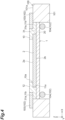
FIG. 4 is a sectional view illustrating a state where the sample support unit is fixed with a holder. -
FIG. 5 is a sectional view illustrating the sample support unit before being fixed with the holder. -
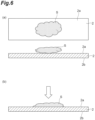
FIGS. 6(a) and 6(b) are diagrams for describing a sample ionization method. -
FIGS. 7(a) and 7(b) are diagrams for describing the sample ionization method. -
FIG. 8 is a sectional view illustrating a state where a substrate is bent in a comparative example. -
FIG. 9 is a sectional view illustrating a fixed state in another comparative example. -
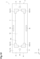
FIG. 10 is a plan view of a sample support unit of a first modification example. -
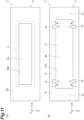
FIG. 11(a) is a bottom view of a sample support unit of a second modification example, andFIG. 11(b) is a bottom view of a sample support unit of a third modification example. - Hereinafter, an embodiment of the present disclosure will be described in detail with reference to the drawings. In the following description, the same reference numerals will be applied to the same or corresponding constituents, and the repeated description will be omitted.
- A
sample support unit 1 illustrated inFIG. 1 to FIG. 5 , for example, is used to ionize the components of a sample, which is a measurement target, in mass analysis. The sample, for example, is a biological sample or the like. Thesample support unit 1 includes asubstrate 2 and aframe 3. - The
substrate 2, for example, is formed of an insulating material in a rectangular plate shape, and has afirst surface 2a, and asecond surface 2b on a side opposite to thefirst surface 2a. Thefirst surface 2a and thesecond surface 2b are the main surface of thesubstrate 2, and for example, a flat surface perpendicular to a thickness direction of thesubstrate 2. The length of one side of thesubstrate 2 when viewed in the thickness direction of thesubstrate 2, for example, is approximately several cm, and the thickness of thesubstrate 2, for example, is approximately 1 µm to 1000 µm. Hereinafter, the thickness direction of the substrate 2 (a direction perpendicular to thefirst surface 2a) will be described as a Z direction, a direction perpendicular to the Z direction will be described as an X direction, and a direction perpendicular to the Z direction and the X direction will be described as a Y direction. The X direction is a direction parallel to the long side of thesubstrate 2. - In the
substrate 2, a porous structure communicating thefirst surface 2a and thesecond surface 2b with each other is formed. In this example, the porous structure has a structure in which voids (air gaps) (pores) extend in an irregular direction and are irregularly distributed in three dimensions (an irregular porous structure). The voids in the porous structure form through holes opened to thefirst surface 2a and thesecond surface 2b. The irregular porous structure, for example, is a sponge-shaped structure. In this example, the porous structure is formed over the entirefirst surface 2a, but the porous structure may be formed in a part of thefirst surface 2a. - In this example, the
substrate 2 is formed of a sintered body of glass beads. The sintered body of the glass beads, for example, has a structure in which a plurality of glass beads are integrated by sintering. The shape of each of the glass beads, for example, is a spherical shape. The shapes and the sizes of the glass beads contained in thesubstrate 2 may be even, or may be uneven. The porous structure described above is formed of the plurality of glass beads and a plurality of voids formed between the glass beads. The voids between the glass beads are irregularly communicated with each other. The average particle size (diameter) of the glass beads, for example, is approximately 50 µm. In a case where thesubstrate 2 is formed of the sintered body of the glass beads, the porosity of the porous structure, for example, is 40% to 50%. - The
first surface 2a of thesubstrate 2 has electrical conductivity. In this example, a conductive layer is formed on thefirst surface 2a. The conductive layer covers the entirefirst surface 2a except for the opening portion of the porous structure. The conductive layer, for example, is formed of a metal material such as Pt. - The
frame 3 is a member that is removably attached to thesubstrate 2, and retains thesubstrate 2 such that a part of thefirst surface 2a is exposed. Theframe 3 is a member different from thesubstrate 2, which is independent from thesubstrate 2. In this example, theframe 3 is formed of a metal material having electrical conductivity, and has high rigidity. Examples of the material of theframe 3 include stainless steel (SUS), aluminum, a ferrous alloy, and the like. - The
frame 3 includes afirst member 10 disposed on thefirst surface 2a side, and asecond member 20 disposed on thesecond surface 2b side. In this example, thefirst member 10 is formed in a rectangular frame shape, and defines arectangular opening 10a. The long side of theopening 10a extends along the long side of the substrate 2 (along the X direction). Theopening 10a is formed in a rectangular shape slightly smaller than thesubstrate 2 when viewed in the Z direction. In a state where theframe 3 is attached to the substrate 2 (FIG. 1 ), a part (the center portion) of thefirst surface 2a is exposed from theopening 10a. - The
first member 10 includes amain body portion 11 formed in a rectangular frame shape, and a holdingportion 12 provided on one side of themain body portion 11 in the Z direction. The entiremain body portion 11 is positioned outside thesubstrate 2 when viewed in the Z direction. Themain body portion 11 defines arectangular opening 11a. The long side of theopening 11a extends along the long side of the substrate 2 (along the X direction). Theopening 11a is formed in a shape corresponding to the substrate 2 (a rectangular shape) when viewed in the Z direction, and thesubstrate 2 is tightly disposed in theopening 11a. - The holding
portion 12 is formed on asurface 11b of themain body portion 11, and has a rectangular frame shape in which the length in the X direction is shorter than that of themain body portion 11. The holdingportion 12 protrudes toward the center side of theframe 3 from themain body portion 11, and a step is formed between the holdingportion 12 and themain body portion 11. Theopening 10a described above is defined by the holdingportion 12. The thickness of the holdingportion 12, for example, is approximately 1 mm. - In this example, the
second member 20 is formed in a rectangular plate shape corresponding to thefirst member 10. Thesecond member 20 covers the entiresecond surface 2b, in a state where theframe 3 is attached to the substrate 2 (FIG. 1 ). - The
frame 3 includes a fixingportion 31 formed by an overlapping portion of thefirst member 10 and thesecond member 20. Theentire fixing portion 31 is positioned outside the substrate 2 (outside the outer edge of the substrate 2) when viewed in the Z direction. InFIG. 2 , for ease of understanding, the fixingportion 31 is hatched. In this example, the fixingportion 31 is provided in each of one end portion and the other end portion of theframe 3 in the X direction, and each of the fixingportions 31 is formed in a rectangular shape having a long side parallel to the Y direction. Each of the fixingportions 31 has asurface 31a positioned on the same plane as that of thefirst surface 2a. In this example, thesurface 31a is formed by thesurface 11b of themain body portion 11 of thefirst member 10. That is, thesurface 11b of themain body portion 11 is positioned on the same plane as that of thefirst surface 2a. The thickness of the fixingportion 31, for example, is approximately 1.5 mm. - As illustrated in
FIG. 1 , theframe 3 is attached to thesubstrate 2 to retain thesubstrate 2. For example, by disposing thesubstrate 2 between thefirst member 10 and thesecond member 20, the separation of thesecond member 20 from theframe 3 is prevented by the holdingportion 12, and thesubstrate 2 is retained in theframe 3. In this example, in a state where theframe 3 is attached to thesubstrate 2, thesubstrate 2 is interposed and fixed between the holdingportion 12 and thesecond member 20. As described above, in such a state, a part (the center portion) of thefirst surface 2a is exposed from theopening 10a. In detachment, for example, it is possible to detach theframe 3 from thesubstrate 2 by separating thefirst member 10 from thesecond member 20, and then, taking out thesubstrate 2. - As illustrated in
FIG. 4 , thesample support unit 1 is fixed by aholder 100. Theholder 100 includes a holdermain body 101, and a plurality of (in this example, four) clampingportions 102. The holdermain body 101, for example, is formed in a rectangular frame shape. Each of the clampingportions 102, for example, is configured by including acontact member 103 and a biasingmember 104. Thecontact member 103 is fixed to asurface 101a of the holdermain body 101. Thecontact member 103 is disposed to protrude toward the center side of the holdermain body 101 from the holdermain body 101. - The biasing
member 104 is disposed to face thecontact member 103 in the Z direction. The biasingmember 104, for example, is configured by including a spring, and capable of biasing thesample support unit 1 disposed between the biasingmember 104 and thecontact member 103 toward thecontact member 103. As an example, two clampingportions 102 among four clampingportions 102 are disposed on one side in the X direction and arranged in the Y direction, and the rest two clampingportions 102 are disposed on the other side in the X direction and arranged in the Y direction. - In
FIG. 5 , thesample support unit 1 before being fixed by theholder 100 is illustrated. As illustrated inFIG. 5 , in this example, in a state before fixation, thefirst member 10 and thesecond member 20 are not in contact with each other. That is, in this example, a gap D between the holdingportion 12 of thefirst member 10 and thesecond member 20 is larger than the thickness of thesubstrate 2. For example, the gap D is approximately 0.5 mm larger than the thickness of thesubstrate 2. - In
FIG. 4 , a state where thesample support unit 1 is fixed by theholder 100 is illustrated. By interposing the fixingportion 31 of theframe 3 between the clampingportions 102 from the state illustrated inFIG. 5 , thesample support unit 1 is fixed. In such a fixed state, thefirst member 10 and thesecond member 20 are brought into contact with each other by the pressing force of the clampingportions 102, and thesubstrate 2 is interposed and fixed between the holdingportion 12 of thefirst member 10 and thesecond member 20. That is, thefirst member 10 and thesecond member 20 are formed such that thesubstrate 2 is interposed between thefirst member 10 and thesecond member 20 in the fixed state. In the fixed state, the fixingportion 31 of theframe 3 is interposed between the clampingportions 102, but thesubstrate 2 is not interposed between the clampingportions 102. - More specifically, in the fixed state, the
contact member 103 of the clampingportion 102 is in contact with thesurface 31a of the fixingportion 31, and the biasingmember 104 is in contact with thesecond member 20. Thecontact member 103 is provided on thesurface 101a of the holdermain body 101 to extend in a direction perpendicular to the Z direction. In addition, as described above, thesurface 31a of the fixingportion 31 is positioned on the same plane as that of thefirst surface 2a of thesubstrate 2. Accordingly, thesurface 101a of the holdermain body 101 and thefirst surface 2a of thesubstrate 2 are positioned on the same plane. Thesurface 101a of the holdermain body 101 functions as a measurement surface in mass analysis measurement. Accordingly, by positioning thesurface 101a and thefirst surface 2a (the effective surface of the substrate 2) on the same plane, it is possible to accurately perform the measurement. - An example of a mass analysis method using the
sample support unit 1 will be described. Such a mass analysis method includes a step of ionizing a sample by using the sample support unit 1 (an ionization method), and a step of detecting the ions. First, an example of the sample ionization method using thesample support unit 1 will be described. - In the sample ionization method of this example, first, the components of a sample S are supplied to the
first surface 2a of the substrate 2 (a supplying step). In the supplying step, the sample S is placed on thefirst surface 2a of the substrate 2 (FIG. 6(a) ). Subsequently, the sample S is pressed toward thesubstrate 2 side, and the sample S is closely attached to thefirst surface 2a of the substrate 2 (FIG. 6(b) ). Accordingly, the components of the sample S are infiltrated and absorbed into the substrate 2 (FIG. 7(a) ). Subsequently, the sample S is removed (FIG. 7(a) ). According to the steps described above, as illustrated inFIG. 7(b) , thesubstrate 2 retaining the components of the sample S is obtained, and in a state where positional information is stored, the components of the sample S are supplied to thefirst surface 2a of thesubstrate 2. Note that, inFIG. 6(a) , the plan view of thesubstrate 2 is illustrated on the upper side, and the sectional view of thesubstrate 2 is illustrated on the lower side. The same applies toFIG. 7(b) . InFIG. 6(b) andFIG. 7(a) , the sectional view of thesubstrate 2 is illustrated. - Subsequent to the supplying step, the
frame 3 is attached to the substrate 2 (an attaching step). Subsequently, by interposing the fixingportion 31 of theframe 3 between the clampingportions 102 of theholder 100, thesample support unit 1 is fixed (a fixing step). In the fixing step, thesample support unit 1 is fixed such that thesurface 101a of the holdermain body 101 and thefirst surface 2a of thesubstrate 2 are positioned on the same plane by bringing thecontact member 103 of the clampingportion 102 into contact with thesurface 31a of the fixingportion 31. - After the fixing step, the components of the sample S on the
first surface 2a are ionized (an ionizing step). For example, by scanning (irradiating) thefirst surface 2a with laser light in a state where a voltage is applied to the conductive layer on thefirst surface 2a, the components of the sample S on thefirst surface 2a are ionized. Such an ionization method is a laser desorption/ionization method using laser light (an energy line). - The sample ions discharged from the
substrate 2, for example, are detected by an ion detection unit of a mass analysis device (an ion detecting step of the mass analysis method). For example, a ground electrode is provided between thesubstrate 2 and the ion detection unit, and the sample ions are moved toward the ground electrode while being accelerated by a potential difference between the conductive layer and the ground electrode. Then, the sample ions are detected by the ion detection unit, and the mass analysis measurement for the sample S is implemented. The ion detection unit detects the sample ions, in association with the scanning position of the laser light. The mass analysis device, for example, is a device performing mass analysis for the sample S by using time-of-flight mass spectrometry (TOF-MS). - The
sample support unit 1 includes theframe 3 that is removably attached to thesubstrate 2, and retains thesubstrate 2 such that a part of thefirst surface 2a is exposed, and theframe 3 includes the fixingportion 31 positioned outside thesubstrate 2 when viewed in the Z direction (the direction perpendicular to thefirst surface 2a), in the state of being attached to thesubstrate 2. Accordingly, by interposing the fixingportion 31 between the clampingportions 102 of theholder 100, it is possible to fix thesample support unit 1. In this case, since it is possible for theframe 3 to receive the pressing force from the clampingportions 102, it is possible to suppress the bending of thesubstrate 2 due to the pressing force from the clampingportions 102, without depending on the strength of thesubstrate 2. As described above, according to such asample support unit 1, it is possible to suppress the bending of thesubstrate 2 during fixation. In addition, in thesample support unit 1, for example, even in a case where the shape of theholder 100 is changed, it is sufficient that the shape of theframe 3 is changed in accordance with the change, and it is not necessary to change the design of thesubstrate 2. In addition, since theframe 3 is separated from thesubstrate 2, it is sufficient to replace only thesubstrate 2, and it is possible to reduce the replacement frequency of theframe 3. - Such a respect will be further described with reference to
FIG. 8 . As illustrated inFIG. 8 , in a case where asubstrate 55 is interposed and fixed between clampingportions 51 of a holder consisting of acontact member 52 and a biasingmember 53, there is a possibility that thesubstrate 55 is bent by the pressing force from the biasingmember 53. In contrast, in thesample support unit 1 of the embodiment, since thesubstrate 2 is fixed by interposing the fixingportion 31 of theframe 3 between the clampingportions 102, without interposing thesubstrate 2, it is possible to suppress the bending of thesubstrate 2 during fixation. - On the other hand, as illustrated in
FIG. 9 , even in a case where thesubstrate 55 is pressed and fixed to thecontact member 52 by the pressing force from the biasingmember 53, for example, there is a possibility that thesubstrate 55 is damaged by the pressing force from the biasingmember 53 when the biasingmember 53 is in contact with the porous structure. In contrast, in thesample support unit 1 of the embodiment, since thesubstrate 2 is fixed by interposing the fixingportion 31 of theframe 3 between the clampingportions 102, without interposing thesubstrate 2, it is possible to suppress the damage of thesubstrate 2 during fixation. - The fixing
portion 31 has thesurface 31a positioned on the same plane as that of thefirst surface 2a. Accordingly, when fixing thesample support unit 1 by interposing the fixingportion 31 between the clampingportions 102 of theholder 100, it is possible to position thesurface 101a (the measurement surface) of the holdermain body 101 of theholder 100 and thefirst surface 2a of thesubstrate 2 on the same plane, and accurately perform the measurement. The mass analysis device may be designed or optimized such that thesurface 101a is the measurement surface (the irradiation point of laser light, the point of origin of time-of-flight analysis), which is because it is considered that a decrease in an ionization efficiency or a shift in flight time occurs due to discordance in the focal range of the laser irradiation in a case where thesurface 101a and thefirst surface 2a are not positioned on the same plane. - The
frame 3 has thefirst member 10 disposed on thefirst surface 2a side, and thesecond member 20 disposed on thesecond surface 2b side. Accordingly, it is possible to reliably retain thesubstrate 2 with thefirst member 10 and thesecond member 20. - The fixing
portion 31 is composed of the overlapping portion of thefirst member 10 and thesecond member 20. Accordingly, it is possible to increase the strength of the fixingportion 31, and further suppress the bending of thesubstrate 2 during fixation. - The
first member 10 is formed in a frame shape. In addition, thesecond member 20 is formed in a plate shape to cover the entiresecond surface 2b in a state where theframe 3 is attached to thesubstrate 2. Accordingly, it is possible to reliably retain thesubstrate 2. - The
first member 10 and thesecond member 20 are formed such that thesubstrate 2 is interposed between thefirst member 10 and thesecond member 20 in a state where theframe 3 is attached to thesubstrate 2. Accordingly, it is possible to reliably retain thesubstrate 2. - The
frame 3 is formed of the metal material having electrical conductivity. Accordingly, it is possible to facilitate the application of a voltage to thefirst surface 2a when ionizing the sample. In addition, it is possible to increase the strength of theframe 3, and further suppress the bending of thesubstrate 2 during fixation. - The porous structure is formed of the sintered body of the glass beads. Accordingly, it is possible to preferably configure the porous structure.
- The
sample support unit 1 may be configured as with a first modification example illustrated inFIG. 10 . In the embodiment described above, the holdingportion 12 is formed to hold thesubstrate 2 over the entire circumference, but in the first modification example, the holdingportion 12 is formed to partially hold thesubstrate 2. The holdingportion 12 of the first modification example has four (a plurality of)portions 12a formed in an approximately L shape when viewed in the Z direction. Fourportions 12a are disposed in positions corresponding to four corners of thesubstrate 2, respectively. In this example, a part of thefirst surface 2a of thesubstrate 2 is exposed between fourportions 12a. - In addition, in the first modification example,
calibration regions frame 3. Thecalibration regions surface 11b of themain body portion 11. As described above, thesurface 11b of themain body portion 11 is positioned on the same plane as that of thefirst surface 2a of thesubstrate 2. That is, the surfaces of thecalibration regions first surface 2a. Twocalibration regions 35 are provided, in which onecalibration region 35 is disposed in one side portion of theframe 3 in the X direction, and theother calibration region 35 is disposed in the other side portion of theframe 3 in the X direction. Each of thecalibration regions 35, for example, is formed in a circular shape. Twocalibration regions 36 are provided, in which onecalibration region 36 is disposed in one side portion of theframe 3 in the Y direction, and theother calibration region 36 is disposed in the other side portion of theframe 3 in the Y direction. Each of thecalibration regions 36, for example, is formed in a rectangular shape having a long side parallel to the X direction. - The
calibration region 35 is visually identifiable from a region adjacent to thecalibration region 35 in theframe 3. That is, regions adjacent to thecalibration region 35 and thecalibration region 35 can be distinguishable with human eyes. A method for making thecalibration region 35 identifiable may be any method, and for example, a groove may be formed around thecalibration region 35 by half-etching, or a mark may be engraved by laser. Similarly, thecalibration region 36 is visually identifiable from the region adjacent to thecalibration region 36. - The
calibration regions calibration regions - According to such a first modification example, as with the embodiment described above, it is also possible to suppress the bending of the
substrate 2 during fixation. In addition, thecalibration regions frame 3. In this case, for example, it is possible to widely ensure a region for measurement on thesubstrate 2, compared to a case where the calibration region is formed on thesubstrate 2. In addition, since the surface of theframe 3 in thecalibration regions first surface 2a of thesubstrate 2, it is possible to accurately perform the mass calibration. Since the time-of-flight shift of the ions strongly depends on a depth direction of an occurrence position, but an influence due to a position in the same plane is small, it is important that the surface of theframe 3 in thecalibration regions first surface 2a of thesubstrate 2. - The
sample support unit 1 may be configured as with a second modification example illustrated inFIG. 11(a) . In the second modification example, thesecond member 20 is formed in a rectangular frame shape, and defines a rectangular opening 20a. The long side of the opening 20a extends along the long side of the substrate 2 (along the X direction). The opening 20a is formed in a rectangular shape slightly smaller than thesubstrate 2 when viewed in the Z direction. In a state where theframe 3 is attached to thesubstrate 2, a part (the center portion) of thesecond surface 2b is exposed from the opening 20a. According to such a second modification example, as with the embodiment described above, it is also possible to suppress the bending of thesubstrate 2 during fixation. In addition, since thesecond member 20 is formed in a frame shape, it is possible to visually check the state of thesubstrate 2 from thesecond surface 2b side. - The
sample support unit 1 may be configured as with a third modification example illustrated inFIG. 11(b) . In the third modification example, theframe 3 has only thefirst member 10 without having thesecond member 20. In this case, the fixingportion 31 is formed by thefirst member 10 only. Thefirst member 10 is provided with fourclaw portions 15 engaged with thesecond surface 2b of thesubstrate 2. Twoclaw portions 15 are disposed in one long side portion of thefirst member 10, and the other twoclaw portions 15 are disposed in the other long side portion of thefirst member 10. Each of theclaw portions 15 is rotatable around a fixing part with respect to thefirst member 10 as indicated by an arrow inFIG. 11(b) . As illustrated inFIG. 11(b) , in a state where theclaw portion 15 protrudes from thefirst member 10, theclaw portion 15 is engaged with thesecond surface 2b of thesubstrate 2 to prevent the separation of thesubstrate 2 from theframe 3. On the other hand, thesubstrate 2 can be attached to or detached from theframe 3, in a state where the claw portion is rotated to a position where theclaw portion 15 does not protrude from thefirst member 10. - According to such a third modification example, as with the embodiment described above, it is also possible to suppress the bending of the
substrate 2 during fixation. In addition, since theclaw portion 15 is provided in thefirst member 10, it is possible to retain thesubstrate 2 by engaging theclaw portion 15 with thesecond surface 2b. In addition, since theclaw portion 15 is movable between a position where the claw portion is engaged with thesecond surface 2b and a position where the claw portion is not engaged with thesecond surface 2b, it is possible to easily engage theclaw portion 15 with thesecond surface 2b. - The present disclosure is not limited to the embodiment and the modification examples described above. The materials and the shapes of each of the configurations are not limited to the materials and the shapes described above, and various materials and shapes can be adopted. For example, the porous structure of the
substrate 2 may be formed of porous glass or a fiber porous body. The porous glass is a sponge-shaped glass plate in which a plurality of pores are irregularly formed and linked. The fiber porous body has a structure (an aggregate) in which a plurality of linear cellulose nanofibers overlap with each other. The fiber porous body, for example, may have a structure in which a plurality of carbon nanofibers, a plurality of fibrous porous silicas, a plurality of glass fibers, or combinations thereof overlap with each other. - The porous structure of the
substrate 2 may be formed of anodically oxidized silicon or an anodically oxidized valve metal. In this case, the porous structure has a plurality of through holes formed to communicate thefirst surface 2a and thesecond surface 2b of thesubstrate 2 with each other. Such through holes, for example, are a plurality of pores extending along the thickness direction of thesubstrate 2, and in this case, the porous structure has a structure in which the plurality of pores are regularly disposed (a regular porous structure). - A case where the porous structure is formed of the anodically oxidized valve metal (for example, aluminum (Al)) will be further described. The porous structure, for example, may be an Al alumina porous film. Specifically, such a porous structure can be obtained by performing an anodization treatment with respect to an Al substrate, and peeling off the oxidized surface portion from the Al substrate. Note that, the porous structure may be formed by anodically oxidizing a valve metal other than Al, such as tantalum (Ta), niobium (Nb), titanium (Ti), hafnium (Hf), zirconium (Zr), zinc (Zn), tungsten (W), bismuth (Bi), and antimony (Sb).
- The porous structure of the
substrate 2 may be formed of porous ceramic or a porous metal. The structure of the porous ceramic is in a sponge shape in which a plurality of pores are irregularly formed and linked, as with the porous glass. The porous metal is a sponge-shaped metal perforated body (may be referred to as a metal porous body, a foam metal, a porous metal, a perforated metal, or the like) in which a plurality of pores are irregularly formed and linked. - The conductive layer may not be formed on the
first surface 2a of thesubstrate 2, and thefirst surface 2a may have electrical insulating properties. In this case, for example, the sample S can be ionized by a desorption electrospray ionization method in which the sample S is desorbed and ionized by irradiating the sample S with electrically charged minute liquid droplets. In the embodiment described above, the porous structure formed in thesubstrate 2 is opened to thefirst surface 2a and thesecond surface 2b, but it is sufficient that the porous structure is capable of absorbing the components of the sample S supplied to thefirst surface 2a, and the porous structure may be opened only to thefirst surface 2a. - In the supplying step described above, the components of the sample S are supplied to the
first surface 2a by placing the sample S on thefirst surface 2a of thesubstrate 2, but instead of this, thesample support unit 1 may be disposed on the sample S such that thesecond surface 2b is brought into contact with the sample S. In this case, the components of the sample S are moved toward thefirst surface 2a side from thesecond surface 2b side through a plurality of paths (the voids in the porous structure) formed in thesubstrate 2 by a capillary action. The components of the sample S moved to thefirst surface 2a side remain on thefirst surface 2a side by a surface tension. As described above, the components of the sample S may be supplied to thefirst surface 2a. - In the ionization method described above, the fixing step is implemented after the supplying step, but the supplying step may be implemented after the fixing step. That is, the components of the sample S may be supplied to the
first surface 2a of thesubstrate 2 after fixing thesample support unit 1 with theholder 100 by attaching theframe 3 to thesubstrate 2. Here, in a case where the fixing step is implemented after the supplying step, as with the ionization method described above, it is preferable since theframe 3 does not interfere when placing the sample S on thefirst surface 2a. - In the embodiment described above, the
frame 3 may have only thesecond member 20 without having thefirst member 10. In this case, theframe 3 may retain thesubstrate 2 such that the entirefirst surface 2a is exposed. That is, it is sufficient that theframe 3 retains thesubstrate 2 such that at least a part of thefirst surface 2a is exposed. In a case where theframe 3 has only thesecond member 20, the fixingportion 31 is formed by thesecond member 20 only. In the example illustrated inFIG. 5 , in a state before thesample support unit 1 is fixed with theholder 100, thefirst member 10 and thesecond member 20 are not in contact with each other, but in a state before fixation, thefirst member 10 and thesecond member 20 may be in contact with each other. - 1: sample support unit, 2: substrate, 2a: first surface (effective surface of substrate 2), 2b: second surface, 3: frame, 10: first member, 15: claw portion, 20: second member, 31: fixing portion, 31a: surface, 35, 36: calibration region, 100: holder, 101a: surface (measurement surface), 102: clamping portion, S: sample.
Claims (13)
- A sample support unit used for ionization of a sample, the unit comprising:a substrate including a first surface, and a second surface on a side opposite to the first surface, and including a porous structure formed therein and opened to at least the first surface; anda frame removably attached to the substrate and retaining the substrate such that at least a part of the first surface is exposed,wherein the frame includes a fixing portion positioned outside the substrate when viewed in a direction perpendicular to the first surface, in a state of being attached to the substrate.
- The sample support unit according to claim 1,
wherein the fixing portion includes a surface positioned on the same plane as that of the first surface. - The sample support unit according to claim 1 or 2,
wherein the frame includes a first member disposed on a side of the first surface, and a second member disposed on a side of the second surface. - The sample support unit according to claim 3,
wherein the fixing portion is formed by an overlapping portion of the first member and the second member. - The sample support unit according to claim 3 or 4,
wherein the first member is formed in a frame shape. - The sample support unit according to any one of claims 3 to 5,
wherein the second member is formed in a plate shape such that the frame covers an entirety of the second surface in a state of being attached to the substrate. - The sample support unit according to any one of claims 3 to 5,
wherein the second member is formed in a frame shape. - The sample support unit according to any one of claims 3 to 7,
wherein the first member and the second member are formed such that the substrate is interposed between the first member and the second member in a state in which the frame is attached to the substrate. - The sample support unit according to claim 1 or 2,wherein the frame includes a first member disposed on a side of the first surface, andthe first member is provided with a claw portion engaged with the second surface.
- The sample support unit according to any one of claims 1 to 9,wherein the frame is formed with a calibration region used for mass calibration and the calibration region is visually identifiable from a region adjacent to the calibration region, anda surface of the calibration region is positioned on the same plane as that of the first surface.
- The sample support unit according to any one of claims 1 to 10,
wherein the porous structure is formed of a sintered body of glass beads, porous glass, a fiber porous body, anodically oxidized silicon, an anodically oxidized valve metal, porous ceramic, or a porous metal. - A sample ionization method using the sample support unit according to any one of claims 1 to 11, the method comprising:a supplying step of supplying components of the sample to the first surface;a fixing step of fixing the sample support unit by interposing the fixing portion of the frame between clamping portions of a holder; andan ionizing step of ionizing the components of the sample on the first surface after the supplying step and the fixing step.
- The sample ionization method according to claim 12,
wherein in the fixing step, the sample support unit is fixed such that a surface of the holder and the first surface are positioned on the same plane.
Applications Claiming Priority (2)
| Application Number | Priority Date | Filing Date | Title |
|---|---|---|---|
| JP2021208138A JP2023092872A (en) | 2021-12-22 | 2021-12-22 | SAMPLE SUPPORT UNIT AND SAMPLE IONIZATION METHOD |
| PCT/JP2022/033189 WO2023119738A1 (en) | 2021-12-22 | 2022-09-02 | Sample support unit, and sample ionization method |
Publications (1)
| Publication Number | Publication Date |
|---|---|
| EP4379368A1 true EP4379368A1 (en) | 2024-06-05 |
Family
ID=86901826
Family Applications (1)
| Application Number | Title | Priority Date | Filing Date |
|---|---|---|---|
| EP22910465.8A Withdrawn EP4379368A1 (en) | 2021-12-22 | 2022-09-02 | Sample support unit, and sample ionization method |
Country Status (5)
| Country | Link |
|---|---|
| US (1) | US20250003843A1 (en) |
| EP (1) | EP4379368A1 (en) |
| JP (1) | JP2023092872A (en) |
| CN (1) | CN118475825A (en) |
| WO (1) | WO2023119738A1 (en) |
Families Citing this family (1)
| Publication number | Priority date | Publication date | Assignee | Title |
|---|---|---|---|---|
| JP7404195B2 (en) * | 2020-09-04 | 2023-12-25 | 浜松ホトニクス株式会社 | Sample support, ionization method, and mass spectrometry method |
Family Cites Families (9)
| Publication number | Priority date | Publication date | Assignee | Title |
|---|---|---|---|---|
| JP2007192673A (en) * | 2006-01-19 | 2007-08-02 | Shimadzu Corp | Sample plate |
| JP2014021048A (en) * | 2012-07-23 | 2014-02-03 | Jeol Ltd | Sample plate and mass spectroscope |
| US9412572B2 (en) * | 2012-10-28 | 2016-08-09 | Perkinelmer Health Sciences, Inc. | Sample holders and methods of using them |
| JP6205299B2 (en) * | 2014-03-31 | 2017-09-27 | シチズンファインデバイス株式会社 | Sample loading plate |
| WO2017038710A1 (en) * | 2015-09-03 | 2017-03-09 | 浜松ホトニクス株式会社 | Sample supporting body and method of manufacturing sample supporting body |
| WO2019155741A1 (en) | 2018-02-09 | 2019-08-15 | 浜松ホトニクス株式会社 | Sample support |
| JP2020020588A (en) * | 2018-07-30 | 2020-02-06 | 浜松ホトニクス株式会社 | Sample support, sample ionization method, and mass spectrometry |
| JP7333280B2 (en) * | 2020-02-04 | 2023-08-24 | 浜松ホトニクス株式会社 | SAMPLE SUPPORT AND METHOD FOR MANUFACTURING SAMPLE SUPPORT |
| JP6918170B1 (en) * | 2020-03-31 | 2021-08-11 | 浜松ホトニクス株式会社 | Sample support |
-
2021
- 2021-12-22 JP JP2021208138A patent/JP2023092872A/en active Pending
-
2022
- 2022-09-02 US US18/708,663 patent/US20250003843A1/en active Pending
- 2022-09-02 CN CN202280084157.XA patent/CN118475825A/en active Pending
- 2022-09-02 WO PCT/JP2022/033189 patent/WO2023119738A1/en not_active Ceased
- 2022-09-02 EP EP22910465.8A patent/EP4379368A1/en not_active Withdrawn
Also Published As
| Publication number | Publication date |
|---|---|
| US20250003843A1 (en) | 2025-01-02 |
| CN118475825A (en) | 2024-08-09 |
| WO2023119738A1 (en) | 2023-06-29 |
| JP2023092872A (en) | 2023-07-04 |
Similar Documents
| Publication | Publication Date | Title |
|---|---|---|
| EP3214436B1 (en) | Surface-assisted laser desorption/ionization method, mass spectrometry method and mass spectrometry device | |
| US20220260528A1 (en) | Sample support body | |
| US6825478B1 (en) | MALDI plate with removable magnetic insert | |
| EP3686590B1 (en) | Laser desorption/ionization method and mass spectrometry method | |
| CN111094967B (en) | Sample support | |
| US20250003843A1 (en) | Sample support unit, and sample ionization method | |
| EP4092717A1 (en) | Sample support | |
| EP3751271B1 (en) | Sample support, ionization method, and mass spectrometry method | |
| EP4382903A1 (en) | Sample support | |
| US11658018B2 (en) | Sample support body | |
| CN113574374B (en) | Sample support, ionization method and mass analysis method | |
| CN113574372B (en) | Sample support, ionization method and mass analysis method | |
| WO2019155740A1 (en) | Sample support, and manufacturing method of sample support |
Legal Events
| Date | Code | Title | Description |
|---|---|---|---|
| STAA | Information on the status of an ep patent application or granted ep patent |
Free format text: STATUS: THE INTERNATIONAL PUBLICATION HAS BEEN MADE |
|
| PUAI | Public reference made under article 153(3) epc to a published international application that has entered the european phase |
Free format text: ORIGINAL CODE: 0009012 |
|
| STAA | Information on the status of an ep patent application or granted ep patent |
Free format text: STATUS: REQUEST FOR EXAMINATION WAS MADE |
|
| 17P | Request for examination filed |
Effective date: 20240226 |
|
| AK | Designated contracting states |
Kind code of ref document: A1 Designated state(s): AL AT BE BG CH CY CZ DE DK EE ES FI FR GB GR HR HU IE IS IT LI LT LU LV MC MK MT NL NO PL PT RO RS SE SI SK SM TR |
|
| DAV | Request for validation of the european patent (deleted) | ||
| DAX | Request for extension of the european patent (deleted) | ||
| STAA | Information on the status of an ep patent application or granted ep patent |
Free format text: STATUS: THE APPLICATION HAS BEEN WITHDRAWN |
|
| 18W | Application withdrawn |
Effective date: 20250602 |