EP4379307A1 - Artillery weapon - Google Patents
Artillery weapon Download PDFInfo
- Publication number
- EP4379307A1 EP4379307A1 EP22275150.5A EP22275150A EP4379307A1 EP 4379307 A1 EP4379307 A1 EP 4379307A1 EP 22275150 A EP22275150 A EP 22275150A EP 4379307 A1 EP4379307 A1 EP 4379307A1
- Authority
- EP
- European Patent Office
- Prior art keywords
- chamber
- fluid
- buffer
- accumulator
- piston
- Prior art date
- Legal status (The legal status is an assumption and is not a legal conclusion. Google has not performed a legal analysis and makes no representation as to the accuracy of the status listed.)
- Pending
Links
- 239000012530 fluid Substances 0.000 claims abstract description 214
- 239000007853 buffer solution Substances 0.000 claims abstract description 50
- 238000004891 communication Methods 0.000 claims abstract description 28
- 238000006073 displacement reaction Methods 0.000 claims abstract description 7
- 239000000872 buffer Substances 0.000 claims description 158
- 230000033001 locomotion Effects 0.000 claims description 34
- 230000033228 biological regulation Effects 0.000 claims description 4
- 230000007423 decrease Effects 0.000 claims description 4
- ZZUFCTLCJUWOSV-UHFFFAOYSA-N furosemide Chemical compound C1=C(Cl)C(S(=O)(=O)N)=CC(C(O)=O)=C1NCC1=CC=CO1 ZZUFCTLCJUWOSV-UHFFFAOYSA-N 0.000 claims description 3
- 230000001419 dependent effect Effects 0.000 claims description 2
- 238000013016 damping Methods 0.000 description 8
- 238000010304 firing Methods 0.000 description 6
- 238000000034 method Methods 0.000 description 4
- 230000005484 gravity Effects 0.000 description 2
- 238000007689 inspection Methods 0.000 description 1
- 230000003993 interaction Effects 0.000 description 1
- 238000012423 maintenance Methods 0.000 description 1
- 238000004519 manufacturing process Methods 0.000 description 1
- 230000000116 mitigating effect Effects 0.000 description 1
Images



Classifications
-
- F—MECHANICAL ENGINEERING; LIGHTING; HEATING; WEAPONS; BLASTING
- F41—WEAPONS
- F41A—FUNCTIONAL FEATURES OR DETAILS COMMON TO BOTH SMALLARMS AND ORDNANCE, e.g. CANNONS; MOUNTINGS FOR SMALLARMS OR ORDNANCE
- F41A25/00—Gun mountings permitting recoil or return to battery, e.g. gun cradles; Barrel buffers or brakes
- F41A25/16—Hybrid systems
-
- F—MECHANICAL ENGINEERING; LIGHTING; HEATING; WEAPONS; BLASTING
- F41—WEAPONS
- F41A—FUNCTIONAL FEATURES OR DETAILS COMMON TO BOTH SMALLARMS AND ORDNANCE, e.g. CANNONS; MOUNTINGS FOR SMALLARMS OR ORDNANCE
- F41A25/00—Gun mountings permitting recoil or return to battery, e.g. gun cradles; Barrel buffers or brakes
- F41A25/02—Fluid-operated systems
-
- F—MECHANICAL ENGINEERING; LIGHTING; HEATING; WEAPONS; BLASTING
- F41—WEAPONS
- F41A—FUNCTIONAL FEATURES OR DETAILS COMMON TO BOTH SMALLARMS AND ORDNANCE, e.g. CANNONS; MOUNTINGS FOR SMALLARMS OR ORDNANCE
- F41A25/00—Gun mountings permitting recoil or return to battery, e.g. gun cradles; Barrel buffers or brakes
- F41A25/16—Hybrid systems
- F41A25/20—Hydropneumatic systems
Definitions
- the present disclosure relates to an artillery weapon.
- the disclosure is concerned with an artillery weapon with a recoil mitigation system.
- the recoil system comprises a recuperator, also mounted to the carriage, which returns the ordnance to its starting position once recoil energy has been dissipated and the ordnance is at the rearward most point in its stroke.
- the buffers comprise flow restrictors to control flow of fluid into and out of the buffers in response to recoil of the gun barrel. If not damping to the same extent, this can cause the damping to be unbalanced and cause a torque which turns the weapon system (and hence the barrel) to one side during firing. This may result in the gun needing to be repositioned before being fired again and/or exerts extra load on the barrel and carriage, reducing their operational life and stability.
- an artillery weapon which manages recoil such that recoil damping does not cause the weapon system (and hence the barrel) to turn and require to be repositioned before being refired, and which does not cause the barrel to deviate from its set elevation until after the projective being fired has left the barrel, is highly desirable.
- the artillery weapon (10) may comprise a carriage (100) and an ordnance (200) having a barrel (202) having a barrel axis (204) extending along the length of the barrel (202).
- the barrel (202) may be mounted to the carriage (100) such that the barrel (202) is operable to travel along the barrel axis (204) between an in-battery position and an out-of-battery position relative to the carriage (100).
- the artillery weapon (10) may further comprise a multifunction cylinder (300) mounted to, and moveable with the ordnance (200).
- the multifunction cylinder (300) may comprise a regulator unit (302) comprising a fluid housing (304) for retaining a working fluid (306), the fluid housing (304) being in fluid communication with a buffer system (308).
- the regulator unit fluid housing (304) may also be in fluid communication with a hydraulic accumulator chamber (310) via a first flow aperture (312).
- the buffer system (308), regulator unit (302), hydraulic accumulator chamber (310) and first flow aperture (312) may be configured such that displacement of the barrel (202) along the barrel axis (204) from the in-battery position to the out-of-battery position causes fluid flow from the buffer system (308) to the fluid housing (304), and thereby causes fluid flow through the first flow aperture (312) into the first accumulator sub-chamber region (316), causing the accumulator piston (314) to move along the accumulator chamber (310) in a first direction and thereby cause gas in the second accumulator sub-chamber region (318) to compress.
- the buffer system (308) may be configured to deliver fluid to the fluid housing (304) in response to the barrel (202) moving relative to the carriage (100) when moving from the in-battery position to the out-of-battery position.
- the buffer system (308) may be configured to receive fluid from the fluid housing (304) in response to the barrel (202) moving relative to the carriage (100) when moving from the out-of-battery position to the in-battery position.
- the barrel (202) may be configured to be displaced along the barrel axis (204) from the in-battery position to the out-of-battery position in response to a projectile (400) being fired from the barrel (202), such that recoil energy of the barrel (202) as it moves from the in-battery position to the out-of-battery position is absorbed by gas in the second accumulator sub-chamber region (318).
- the buffer system (308), regulator unit (302), hydraulic accumulator chamber (310) and first flow aperture (312) may be configured such that pressure of compressed gas in the second accumulator sub-chamber region (318) causes the accumulator piston (314) to move along the accumulator chamber (310) in a second direction opposite to the first direction and thereby causes fluid flow through the first flow aperture (312) from the first accumulator sub-chamber region (316) into the fluid housing (304), causing fluid flow from the fluid housing (304) into the buffer system (308) to cause displacement of the barrel (202) along the barrel axis (204) from the out-of-battery position to the in-battery position.
- the buffer system (308), regulator unit (302), hydraulic accumulator chamber (310) and first flow aperture (312) may be configured such that the pressure of compressed gas in the second accumulator sub-chamber region (318) causes the accumulator piston (314) to move along the accumulator chamber (310) in a second direction to the in-battery position after recoil motion of the barrel (202) is complete.
- the accumulator chamber (310) may be in fluid communication with a gas reservoir (320) via a flow passage (322), the gas reservoir (320) having a volume configured to limit gas pressure change in the accumulator chamber (310) during recoil to a predetermined value.
- a control rod (324) may extend from the accumulator piston (314) from the first accumulator sub-chamber region (316) through the first flow aperture (312) into the fluid housing (304).
- the control rod (324) may be moveable with the accumulator piston (314).
- the control rod (324) may increase in diameter along its length from the accumulator piston (314).
- the diameter of the control rod (324) may be smaller than the cross-sectional area of the first flow aperture (312) along at least some of the stroke of the accumulator piston (314) such that as the control rod (324) moves relative to the first flow aperture (312) from the fluid housing (304) into the first accumulator sub-chamber region (316), the flow area around the control rod (324) decreases to thereby increase resistance to flow of fluid from the fluid housing (304) into the first accumulator sub-chamber region (316).
- the fluid housing (304) may define a fluid housing chamber (360) for retaining the working fluid (306).
- a control rod support piston (326) may be mounted to the control rod (324) in, and operable to move along, the fluid housing chamber (360), to define a first fluid housing sub-chamber region (362) on one side of the control rod piston (326) and a second fluid housing sub-chamber region (364) on the other side of the control rod support piston (326).
- the control rod support piston (326) may be spaced apart from the accumulator piston (314) along the length of the control rod (324).
- the control rod support piston (326) may define passages (328) for the regulation of fluid flow between the first fluid housing sub-chamber region (362) and the second fluid housing sub-chamber region (364).
- the buffer system (308) may comprise a first plain buffer (330) mounted to the carriage (100) on a first side (332) of the ordnance (200) and a second plain buffer (340) mounted to the carriage (100) on a second side (342) of the ordnance (200) each of the first plain buffer (330) and second plain buffer (340) being hydro pneumatic and comprising a buffer cylinder (334, 344) and a buffer piston (336, 346) slideable within/relative to the buffer cylinder (334, 344).
- the first plain buffer cylinder (334) and second plain buffer cylinder (344) may be in fluid communication with the fluid housing (304).
- Movement of the ordnance (200) relative to the carriage (100) from the in-battery position to the out-of-battery position may result in movement of each buffer cylinder (334, 344) relative to its respective buffer piston (336, 346) to cause fluid flow from the buffer system (308) to the fluid housing (304). Movement of the ordnance (200) relative to the carriage (100) from the out-of-battery position to the in-battery position may result in movement of each buffer cylinder (334, 344) relative to its respective buffer piston (336, 346) to permit fluid flow from the fluid housing (304) to the buffer system (308).
- Each buffer cylinder (334, 344) may be mounted to, and operable to move with, the barrel (202) and each buffer piston (336, 346) may be mounted to the carriage (100).
- Each buffer piston (336, 346) may be mounted to, and operable to move with, the barrel (202) and each buffer cylinder (334, 344) may be mounted to the carriage (100).
- the buffer cylinder (334, 344) of each of the first plain buffer (330) and second plain buffer (340) may define a buffer chamber (337, 347).
- the buffer piston (336, 346) in each of the first plain buffer (330) and second plain buffer (340) may be provided in, and operable to move along the respective buffer cylinder (334, 344) to define a first buffer sub-chamber (338, 348) on one side of the buffer piston (336, 346) and a second buffer sub-chamber (339, 349) on the other side of the buffer piston (336, 346).
- Each first buffer sub-chamber (338, 348) may be in fluid communication with the fluid housing (304).
- Each second buffer sub chamber (339, 349) may be open to atmosphere via a port (370, 372).
- the second buffer sub chamber (339, 349) may be closed and configured to be in fluid communication with a source (700) of pressurised fluid, such that flow of pressurised fluid into the second buffer sub chamber (339, 349) causes movement of the ordnance (200) relative to the carriage (100) from the in-battery position to the out-of-battery position.
- the weapon (10) may further comprise a free recoil auxiliary cylinder (600) which defines a free recoil chamber (602).
- a free recoil piston (604) may be provided in, and operable to move along the free recoil chamber (602) to define a first recoil sub-chamber (606) on one side of the free recoil piston (604) and a second recoil sub-chamber (608) on the other side of the second free recoil piston (604).
- the first recoil sub-chamber (606) may define a second fluid flow aperture (610) and the second fluid flow aperture (610) may be in fluid communication with the fluid housing (304) such that movement of the ordnance (200) relative to the carriage (100) from the in-battery position to the out-of-battery position results in movement of the free recoil piston (604) relative to the free recoil auxiliary cylinder (600) to permit fluid flow into to the free recoil chamber (602).
- the second recoil sub-chamber (608) may contain a compressible fluid to provide a resistance to motion of the free recoil piston (604) as the free recoil piston (604) moves along the free recoil chamber (602), the compressible fluid increasing in pressure as the free recoil piston (604) moves along the free recoil chamber (602) such that the force acting on the free recoil piston (604) increases as the free recoil piston (604) moves along the free recoil chamber (602) to increase the resistance to fluid flow into the first recoil sub-chamber (606).
- the predetermined pressure level may be set to a value based on a function of mass of the ordnance (200).
- the buffer system (308), fluid housing (304) of the multifunction cylinder (300) and the first recoil sub-chamber (606) may be fluidly linked by a fluid manifold (500).
- an artillery weapon which manages recoil such that the barrel does not deviate from its aimed position set elevation until after the projective being fired has left the barrel, and in which damping does not cause the barrel to move and require to be reset before being refired.
- an free recoil auxiliary cylinder enables the projectile to leave the gun barrel before recoil starts to be damped, ensuring the barrel remains at its desired orientation and elevation to direct the projectile as desired by the user.
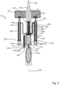
- FIG. 1 to 3 shows a plan view of a first example of an artillery weapon according to the present disclosure in different operational states.
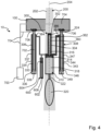
- Figure 4 shows a plan view of a second example of an artillery weapon, in the same state as the first example as shown in figure 1 .
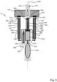
- Figure 5 shows a plan view of a third example of an artillery weapon according to the present disclosure, in the same state as the first example as shown in figure 1 .
- Figure 6 shows a plan view of a fourth example of an artillery weapon according to the present disclosure, in the same state as the first example as shown in figure 1 .
- Each example of the artillery weapon 10 comprises a carriage 100 and an ordnance 200 having a barrel 202.
- the carriage 100 may comprise, or be carried on, a platform for moving the artillery weapon 10, supported from the ground by wheels for transporting the artillery weapon from one location to another.
- the barrel 202 has a barrel axis 204 extending along the length of the barrel 202. That is, the bore of the barrel 202 is centred on the barrel axis 204.
- the barrel 202 is mounted to the carriage 100 such that the barrel 202 is operable to travel along the barrel axis 204 between an in-battery position and an out-of-battery position relative to the carriage 100. That is to say, the barrel 202 is configured to be displaced along the barrel axis 204 from the in-battery position to the out-of-battery position in response to a projectile 400 being fired from the barrel 202.
- “In-battery” defines a forward position of the ordnance 200 before (and ready for) firing.
- the "in-battery” configuration/state of the different examples is shown in figures 1 , 4 , 5 , 6 .
- “Out-of-battery” defines a position of the ordnance 200 when fully recoiled, e.g. after firing.
- the "out-of-battery” configuration/state is shown in figure 3 .
- the cannon moves (i.e. recoils) from an "in-battery” position (as shown in figure 1 ) along the barrel axis 204 to an "out-of-battery” position (as shown in figure 3 ).
- the cannon is then moved from the "out-of-battery” position back along the barrel axis 204 to the "in-battery” position in order to fire again.
- the examples of figures 4 , 5 , 6 work in the same way.
- the artillery weapon 10 comprises a multifunction cylinder 300 mounted to, and moveable with the ordnance 200.
- the multifunction cylinder 300 comprises a regulator unit 302.
- the regulator unit 302 has a fluid housing 304 for retaining a working fluid 306.
- the fluid housing 304 is in fluid communication with a buffer system 308.
- the buffer system 308 is configured to deliver fluid to the fluid housing 304 in response to the barrel 202 moving relative to the carriage 100 when moving from the in-battery position to the out-of-battery position.
- the buffer system 308 is also configured to receive fluid from the fluid housing 304 in response to the barrel 202 moving relative to the carriage 100 when moving from the out-of-battery position to the in-battery position.
- the regulator unit fluid housing 304 is in fluid communication with a hydraulic accumulator chamber 310 via a first flow aperture 312.
- An accumulator piston 314 is provided in, and operable to move along the accumulator chamber 310, to define a first accumulator sub-chamber region 316 on one side of the accumulator piston 314 and a second accumulator sub-chamber region 318 on the other side of the accumulator piston 314.
- the buffer system 308, regulator unit 302, hydraulic accumulator chamber 310 and first flow aperture 312 are configured such that displacement of the barrel 202 along the barrel axis 204 from the in-battery position to the out-of-battery position causes fluid flow from the buffer system 308 to the fluid housing 304, and thereby causes fluid flow through the first flow aperture 312 into the first accumulator sub-chamber region 316, which in turn causes the accumulator piston 314 to move along the accumulator chamber 310 in a first direction and thereby cause gas in the second accumulator sub-chamber region 318 to compress.
- the volume of the first accumulator sub-chamber region 316 and second accumulator sub-chamber region 318 are defined in dependence on the position of the accumulator piston 314 along the accumulator chamber 310.
- the accumulator piston 314 defines a fluid seal between the first accumulator sub-chamber region 316 and second accumulator sub-chamber region 318. Hence the first accumulator sub-chamber region 316 and second accumulator sub-chamber region 318 are fluidly isolated from one another.
- the first flow aperture 312 may be provided as a single orifice in a plate between the regulator unit 302 and accumulator piston 314.
- the first flow aperture 312 may comprise a series of plates, each with an orifice, which define a series of chambers defined by the plates and orifices (orifices same or different sizes), between the regulator unit 302 and accumulator piston 314.
- a control rod 324 extends from the accumulator piston 314 from the first accumulator sub-chamber region 316 through the first flow aperture 312 into the fluid housing 304.
- the diameter of the control rod 324 is smaller than the cross-sectional area of the first flow aperture 312 along at least some of the stroke of the accumulator piston 314. That is to say the diameter of the control rod 324 is smaller than the cross-sectional area of the first flow aperture 312 along at least some of the length of the control rod 324.
- the control rod 324 is moveable with the accumulator piston 314.
- the control rod 324 increases in diameter along its length from the accumulator piston 314.
- the flow area around the control rod 324 decreases to thereby increase resistance to flow of fluid from the fluid housing 304 into the first accumulator sub-chamber region 316 thereby maintaining flow resistance through aperture 312 at the appropriate level as the speed of the recoiling mass slows during the recoil stroke.
- control rod 324 and first flow aperture 312 provides a throttling arrangement for the flow of working fluid during movement of the barrel 202 from the in-battery position to the out-of-battery position.
- the fluid housing 304 defines a fluid housing chamber 360 for retaining the working fluid 306.
- a control rod support piston 326 is mounted to the control rod 324 in, and operable to move along, the fluid housing chamber 360, to define a first fluid housing sub-chamber region 362 on one side of the control rod piston 326 and a second fluid housing sub-chamber region 364 on the other side of the control rod support piston 326.
- the buffer system 308, regulator unit 302, hydraulic accumulator chamber 310 and first flow aperture 312 may be configured such that pressure of compressed gas in the second accumulator sub-chamber region 318 causes the accumulator piston 314 to move along the accumulator chamber 310 in a second direction opposite to the first direction and thereby causes fluid flow through the first flow aperture 312 from the first accumulator sub-chamber region 316 into the fluid housing 304, causing fluid flow from the fluid housing 304 into the buffer system 308.
- Flow in this direction may be un-damped, by allowing it to flow through a larger orifice adjacent to the control orifice. This larger orifice is closed when fluid moves in the first direction, in the manner of a non-return valve.
- This larger orifice is closed when fluid moves in the first direction, in the manner of a non-return valve.
- the first direction and second direction are parallel to the barrel axis 204, and opposite to one another.
- the buffer system 308, regulator unit 302, hydraulic accumulator chamber 310 and first flow aperture 312 are configured such that the pressure of compressed gas in the second accumulator sub-chamber region 318 causes the accumulator piston 314 to move along the accumulator chamber 310 in a second direction to the in-battery position after recoil motion of the barrel 202 is complete.
- the multifunction cylinder 300 thus is configured to act as both the regulator for the buffer system as well as providing a recuperator.
- the recuperator functionality is provided by the second accumulator sub-chamber region 318 which, after recoil, causes the working fluid to flow from the first accumulator sub-chamber region 316 back to the buffer system to cause the ordnance 200 to return to battery.
- the accumulator chamber 310 is in fluid communication with a gas reservoir 320 via a flow passage 322.
- the gas reservoir 320 has a volume configured to limit gas pressure change in the accumulator chamber 310 during recoil to a predetermined value.
- control rod support piston 326 is spaced apart from the accumulator piston 314 along the length of the control rod 324.
- the control rod support piston 326 defines passages 328 for the regulation of fluid flow between the first fluid housing sub-chamber region 362 and the second fluid housing sub-chamber region 364.
- the passages 328 may be configured to allow free passage of fluid.
- the passages 328 may be configured to provide damping to the movement of the control rod 324, and hence the ordnance, for example to prevent a hard stop when the ordnance returns to battery.
- the buffer system 308 comprises a first plain buffer 330 mounted to the carriage 100 on a first side 332 of the ordnance 200 and a second plain buffer 340 mounted to the carriage 100 on a second side 342 of the ordnance 200. That is to say, the buffer system 308 comprises a first plain buffer 330 mounted to the carriage 100 on a first side 332 of the barrel axis 204 and a second plain buffer 340 mounted to the carriage 100 on a second side 342 of the barrel axis 204.
- the first plain buffer 330 and second plain buffer 340 may be mounted in the same plane, wherein the plane may intersect the barrel axis 204 or be offset from the barrel axis 204.
- Each of the first plain buffer 330 and second plain buffer 340 may be hydro pneumatic.
- Each of the first plain buffer 330 and second plain buffer 340 may be a buffer cylinder 334, 344 and a buffer piston 336, 346 slideable within/relative to the buffer cylinder 334, 344. As shown in the figures, a piston rod 333, 343 may extend from each of the pistons 336, 346.
- the first plain buffer cylinder 334 and second plain buffer cylinder 344 are in fluid communication with the fluid housing 304.
- first plain buffer cylinder 334 and second plain buffer cylinder 344 are in fluid communication with the fluid housing 304 via inlets 384, 386 which feed directly in into the first plain buffer cylinder 334 and second plain buffer cylinder 344 respectively.
- first plain buffer cylinder 334 and second plain buffer cylinder 344 are in fluid communication with the fluid housing 304 via flow passages 380, 382 which extend along the buffer piston rods 333, 343 respectively.
- the apparatus is configured such that movement of the ordnance 200 relative to the carriage 100 from the in-battery position to the out-of-battery position results in movement of each buffer cylinder 334, 344 relative to its respective buffer piston 336, 346 to cause fluid flow from the buffer system 308 to the fluid housing 304.
- the buffer cylinder 334, 344 of each of the first plain buffer 330 and second plain buffer 340 define a buffer chamber 337, 347.
- the buffer piston 336, 346 in each of the first plain buffer 330 and second plain buffer 340 is provided in, and operable to move along the respective buffer chamber 336, 346 to define a first buffer sub-chamber 338, 348 on one side of the buffer piston 336, 346 and a second buffer sub-chamber 339, 349 on the other side of the buffer piston 336, 346, and each first buffer sub-chamber 338, 348 is in fluid communication with the fluid housing 304.
- each first buffer sub-chamber 338, 348 and each second buffer sub-chamber 339, 349 are defined in dependence on the position of the respective piston 336, 346 relative to the respective cylinder 334, 344.
- Each buffer cylinder 334, 344 defines a fluid seal between each first buffer sub-chamber 338, 348 and each second buffer sub-chamber 339, 349. Hence each first buffer sub-chamber 338, 348 and each second buffer sub-chamber 339, 349 are fluidly isolated from one another.
- each buffer cylinder 334, 344 is mounted to, and operable to move with, the barrel 202 and each buffer piston 336, 346 is mounted (e.g. coupled / fixed) to the carriage 100. In such examples each buffer piston 336, 346 is mounted (e.g. coupled / fixed) to the carriage 100 via their respective piston rod 333, 343.
- each buffer piston 336, 346 is mounted to, and operable to move with, the barrel 202 and each buffer cylinder 334, 344 is mounted (e.g. coupled / fixed) to the carriage 100. In such examples each buffer piston 336, 346 is mounted (e.g. coupled / fixed) to the barrel 202 via their respective piston rod 333, 343.
- the apparatus of the present disclosure comprises two buffer cylinders arranged on opposite sides of the ordnance.
- the buffer pistons 336, 346 are mounted to the gun carriage (e.g. via their respective piston rods 333, 343), whereas the buffer cylinders are mounted to the ordnance and move with the ordnance as it travels between the in-battery position and out-of-battery position and back again.
- the buffer cylinders are fixed to the carriage, whereas the buffer pistons 336, 346 fixed to the ordnance (e.g. via their respective piston rods 333, 343) and move with the ordnance as it travels between the in-battery position and out-of-battery position and back again.
- the apparatus is thus configured such that movement of the ordnance 200 relative to the carriage 100 from the out-of-battery position to the in-battery position results in movement of each buffer cylinder 334, 344 relative to its respective buffer piston 336, 346 to permit fluid flow from the fluid housing 304 to the buffer system 308.
- each second buffer sub chamber 339, 349 is open to atmosphere via a port 370, 372. That is to say, in the examples of figures 1 to 4 and figure 5 , each second buffer sub chamber 339, 349 is configured to exhaust air to atmosphere, or intake air from the atmosphere, via the port 370, 372.
- the second buffer sub chamber 339, 349 is closed and configured to be in fluid communication with a source 700 of pressurised fluid, such that flow of pressurised fluid into the second buffer sub chamber 339, 349 causes movement of the ordnance 200 relative to the carriage 100 from the in-battery position to the out-of-battery position.
- the second buffer sub chamber 339, 349 is in fluid communication with the source 700 of pressurised fluid via a flow inlet 706 which feeds a flow passage 702 provided in the piston rod 333, 343, such that flow of pressurised fluid into the second buffer sub chamber 339, 349 via the flow inlet 706 and flow passage 702 causes movement of the ordnance 200 relative to the carriage 100 from the in-battery position to the out-of-battery position.
- the second buffer sub chamber 339, 349 is in fluid communication with the source 700 of pressurised fluid via a flow inlet 706 which directly feeds the buffer sub chambers 339, 349 such that flow of pressurised fluid into the second buffer sub chamber 339, 349 via the flow inlet 706 causes movement of the ordnance 200 relative to the carriage 100 from the in-battery position to the out-of-battery position.
- the buffers are linked to a separate hydraulic system which can be used to draw the ordnance out-of-battery, for example to shorten the artillery weapon for transport and/or storage of the gun.
- the separate hydraulic system is compensated as appropriate to account for oil drawn into the buffers on recoil.
- the weapon apparatus 10 may further comprise a free recoil auxiliary cylinder 600 which defines a free recoil chamber 602.
- a free recoil piston 604 is provided in, and operable to move along the free recoil chamber 602 to define a first recoil sub-chamber 606 on one side of the free recoil piston 604 and a second recoil sub-chamber 608 on the other side of the second free recoil piston 604.
- volume of the first recoil sub-chamber 606 and second recoil sub-chamber 608 are defined in dependence on the position of the free recoil piston 604 along the free recoil chamber 602.
- the free recoil piston 604 defines a fluid seal between the first recoil sub-chamber 606 and second recoil sub-chamber 608. Hence the first recoil sub-chamber 606 and second recoil sub-chamber 608 are fluidly isolated from one another.
- the first recoil sub-chamber 606 may define a second fluid flow aperture 610 and the second fluid flow aperture 610 may be in fluid communication with the fluid housing 304.
- the buffer system 308, fluid housing 304 of the multifunction cylinder 300 and the first recoil sub-chamber 606 are fluidly linked by a fluid manifold 500.
- the buffer system 308, fluid housing 304 of the multifunction cylinder 300 and the first recoil sub-chamber 606 are in fluid communication via the fluid manifold 500, such that a pressure change in one cylinder of the system causes change in pressure for all cylinders.
- the second recoil sub-chamber 608 may contains a compressible fluid to provide a resistance to motion of the free recoil piston 604 as the free recoil piston 604 moves along the free recoil chamber 602, the compressible fluid increasing in pressure as the free recoil piston 604 moves along the free recoil chamber 602 such that the force acting on the free recoil piston 604 increases as the free recoil piston 604 moves along the free recoil chamber 602 to increase the resistance to fluid flow into the first recoil sub-chamber 606.
- the pressure in the second recoil sub-chamber 608 may be below a predetermined level and/or while the free recoil piston 604 is moving relative to the free recoil chamber 602, there is no fluid flow from the fluid housing 304 into the first accumulator sub-chamber region 316.
- the predetermined pressure level is set to a value based on a function of mass of the ordnance 200.
- the pressure in the free-recoil cylinder is a function of the mass of the recoiling/moveable components (e.g. the ordnance plus the mass of all the parts of the recoil system that move with it).
- the predetermined pressure level chosen to be sufficiently low so as to require less force to compress (i.e. move piston 604) it than force required to move piston 314.
- the free recoil auxiliary cylinder 600 and free recoil piston 604 thereby a system by which working fluid from the buffers can flow undamped, thereby allowing the ordnance to move undamped during the initial part of a recoil stroke of the ordnance.
- damping only starts when the free recoil piston 604 stops moving relative to the free recoil chamber 602.
- the capacity of the free recoil auxiliary cylinder 600 is chosen such that the projectile has left the gun barrel before the recoil piston 604 stops moving relative to the free recoil chamber 602, and hence before the barrel recoil starts to be damped, ensuring the barrel remains at its desired orientation and elevation to direct the projectile as desired by the user.
- the pressure of compressed gas in the second accumulator sub-chamber region 318 causes the accumulator piston 314 to move along the accumulator chamber 310 in the second direction, thereby displacing fluid from the first accumulator sub-chamber region 316 back into the fluid manifold 500 and buffer system 308 to allow the barrel 202 to return to the in-battery position.
- the configuration of the apparatus of the present disclosure enables for the management of recoil such that the barrel is not caused to move during firing, and therefore improves accuracy during firing and avoids the need for the position of the barrel and/or weapon as a whole to be reset before being refired.
- Throttling of both buffers in a single location results in the recoil load for a symmetrically balanced recoiling mass being balanced symmetrically between the two buffers. This is because the two buffers are not subject to inevitable imbalances in throttling, as would occur if a separate throttle is provided in each buffer (as in examples of the prior art).
- throttling in a single location means that the torque which will be applied to the weapon system (e.g. a gun carriage) is of a more predictable nature, as it is only a function of recoiling mass Centre of Gravity position, not of buffer throttling imbalance between two separately throttled buffers. This predictability may allow for fine adjustment of recoiling mass Centre of Gravity position.
- throttling in a single location means that the two buffers are loaded equally, as they are not subject to the inevitable imbalances of a separate throttle in each buffer.
- recoiling mass CoG position is of a more predictable nature, as it is only a function of recoiling mass CoG position, not of buffer throttling imbalance between two separately throttled buffers. This predictability may allow for fine adjustment of recoiling mass CoG position to correct that imbalance.
- a free recoil auxiliary cylinder enables the projectile to leave the gun barrel before recoil starts to be damped, ensuring the barrel remains at its desired orientation and elevation to direct the projectile as desired by the user.
- the artillery weapon of the present disclosure also provides for variable damping throughout the recoil stroke of the barrel so that the recoil force remains approximately constant as the speed of the recoiling ordnance decreases.
- the artillery weapon of the present disclosure is further advantageous as a substantial part of the recoil system (e.g. the multifunction cylinder 300, and parts of the buffer system 308 for example the buffer cylinders 334, 344 or buffer pistons 336, 346) is mounted on the recoiling ordnance, which thereby increases it recoiling mass and hence reduces recoil force on the carriage. That is to say the arrangement of the present disclosure allows a larger proportion of recoil system to be recoiled, thus increasing recoiling mass and reducing recoil force.
- the recoil system e.g. the multifunction cylinder 300, and parts of the buffer system 308 for example the buffer cylinders 334, 344 or buffer pistons 336, 346
- the arrangement of the present disclosure allows a larger proportion of recoil system to be recoiled, thus increasing recoiling mass and reducing recoil force.
Landscapes
- Engineering & Computer Science (AREA)
- General Engineering & Computer Science (AREA)
- Actuator (AREA)
Abstract
An artillery weapon (10) comprising a carriage (100) and an ordnance (200) having a barrel (202) operable to travel between an in-battery position and an out-of-battery position. The artillery weapon (10) further comprises a multifunction cylinder (300) mounted to, and moveable with the ordnance (200). The multifunction cylinder (300) comprises a regulator unit (302) comprising a fluid housing (304) for retaining a working fluid (306), the fluid housing (304) being in fluid communication with a buffer system (308), the buffer system (308) configured to deliver fluid to, and receive fluid from, the fluid housing (304) in response to the barrel (202) moving relative to the carriage (100). The regulator unit fluid housing (304) is in fluid communication with a hydraulic accumulator chamber (310) via a first flow aperture (312). There is also provided an accumulator piston (314) provided in, and operable to move along the accumulator chamber (310). The buffer system (308), regulator unit (302), hydraulic accumulator chamber (310) and first flow aperture (312) are configured such that displacement of the barrel (202) along the barrel axis (204) from an in-battery position to an out-of-battery position causes fluid flow from the buffer system (308) to the fluid housing (304), and thereby causes fluid flow through the first flow aperture (312) into a first accumulator sub-chamber region (316), causing the accumulator piston (314) to move along the accumulator chamber (310) in a first direction and thereby cause gas in a second accumulator sub-chamber region (318) to compress.
Description
- The present disclosure relates to an artillery weapon.
- In particular the disclosure is concerned with an artillery weapon with a recoil mitigation system.
- It is common for guns, whether towed, fixed, vehicle mounted or otherwise to comprise a recoil system to slow the recoiling ordnance. This slowing over an extended distance reduces the force transmitted to the gun carriage. This attenuation of recoil motion is often performed by hydropneumatic buffers. Conventionally the buffers are mounted to either side of the gun, on the platform (e.g. carriage) that supports the gun.
- It is also common for the recoil system to comprise a recuperator, also mounted to the carriage, which returns the ordnance to its starting position once recoil energy has been dissipated and the ordnance is at the rearward most point in its stroke.
- The buffers comprise flow restrictors to control flow of fluid into and out of the buffers in response to recoil of the gun barrel. If not damping to the same extent, this can cause the damping to be unbalanced and cause a torque which turns the weapon system (and hence the barrel) to one side during firing. This may result in the gun needing to be repositioned before being fired again and/or exerts extra load on the barrel and carriage, reducing their operational life and stability.
- Additionally, conventional systems start to damp the recoil as soon as the weapon is fired (i.e. as soon as the barrel starts to move rearwards and prior to the projectile leaving the barrel), which can cause the barrel to deviate from its set elevation angle, directing the fired projectile off course.
- Hence an artillery weapon which manages recoil such that recoil damping does not cause the weapon system (and hence the barrel) to turn and require to be repositioned before being refired, and which does not cause the barrel to deviate from its set elevation until after the projective being fired has left the barrel, is highly desirable.
- According to the present disclosure there is provided an apparatus and system as set forth in the appended claims. Other features of the invention will be apparent from the dependent claims, and the description which follows.
- Accordingly there may be provided an artillery weapon (10). The artillery weapon (10) may comprise a carriage (100) and an ordnance (200) having a barrel (202) having a barrel axis (204) extending along the length of the barrel (202). The barrel (202) may be mounted to the carriage (100) such that the barrel (202) is operable to travel along the barrel axis (204) between an in-battery position and an out-of-battery position relative to the carriage (100). The artillery weapon (10) may further comprise a multifunction cylinder (300) mounted to, and moveable with the ordnance (200). The multifunction cylinder (300) may comprise a regulator unit (302) comprising a fluid housing (304) for retaining a working fluid (306), the fluid housing (304) being in fluid communication with a buffer system (308). The regulator unit fluid housing (304) may also be in fluid communication with a hydraulic accumulator chamber (310) via a first flow aperture (312). There may be provided an accumulator piston (314) in, and operable to move along, the accumulator chamber (310) to define a first accumulator sub-chamber region (316) on one side of the accumulator piston (314) and a second accumulator sub-chamber region (318) on the other side of the accumulator piston (314). The buffer system (308), regulator unit (302), hydraulic accumulator chamber (310) and first flow aperture (312) may be configured such that displacement of the barrel (202) along the barrel axis (204) from the in-battery position to the out-of-battery position causes fluid flow from the buffer system (308) to the fluid housing (304), and thereby causes fluid flow through the first flow aperture (312) into the first accumulator sub-chamber region (316), causing the accumulator piston (314) to move along the accumulator chamber (310) in a first direction and thereby cause gas in the second accumulator sub-chamber region (318) to compress.
- The buffer system (308) may be configured to deliver fluid to the fluid housing (304) in response to the barrel (202) moving relative to the carriage (100) when moving from the in-battery position to the out-of-battery position. The buffer system (308) may be configured to receive fluid from the fluid housing (304) in response to the barrel (202) moving relative to the carriage (100) when moving from the out-of-battery position to the in-battery position.
- The barrel (202) may be configured to be displaced along the barrel axis (204) from the in-battery position to the out-of-battery position in response to a projectile (400) being fired from the barrel (202), such that recoil energy of the barrel (202) as it moves from the in-battery position to the out-of-battery position is absorbed by gas in the second accumulator sub-chamber region (318).
- The buffer system (308), regulator unit (302), hydraulic accumulator chamber (310) and first flow aperture (312) may be configured such that pressure of compressed gas in the second accumulator sub-chamber region (318) causes the accumulator piston (314) to move along the accumulator chamber (310) in a second direction opposite to the first direction and thereby causes fluid flow through the first flow aperture (312) from the first accumulator sub-chamber region (316) into the fluid housing (304), causing fluid flow from the fluid housing (304) into the buffer system (308) to cause displacement of the barrel (202) along the barrel axis (204) from the out-of-battery position to the in-battery position.
- The buffer system (308), regulator unit (302), hydraulic accumulator chamber (310) and first flow aperture (312) may be configured such that the pressure of compressed gas in the second accumulator sub-chamber region (318) causes the accumulator piston (314) to move along the accumulator chamber (310) in a second direction to the in-battery position after recoil motion of the barrel (202) is complete.
- The accumulator chamber (310) may be in fluid communication with a gas reservoir (320) via a flow passage (322), the gas reservoir (320) having a volume configured to limit gas pressure change in the accumulator chamber (310) during recoil to a predetermined value.
- A control rod (324) may extend from the accumulator piston (314) from the first accumulator sub-chamber region (316) through the first flow aperture (312) into the fluid housing (304). The control rod (324) may be moveable with the accumulator piston (314). The control rod (324) may increase in diameter along its length from the accumulator piston (314). The diameter of the control rod (324) may be smaller than the cross-sectional area of the first flow aperture (312) along at least some of the stroke of the accumulator piston (314) such that as the control rod (324) moves relative to the first flow aperture (312) from the fluid housing (304) into the first accumulator sub-chamber region (316), the flow area around the control rod (324) decreases to thereby increase resistance to flow of fluid from the fluid housing (304) into the first accumulator sub-chamber region (316).
- The fluid housing (304) may define a fluid housing chamber (360) for retaining the working fluid (306). A control rod support piston (326) may be mounted to the control rod (324) in, and operable to move along, the fluid housing chamber (360), to define a first fluid housing sub-chamber region (362) on one side of the control rod piston (326) and a second fluid housing sub-chamber region (364) on the other side of the control rod support piston (326). The control rod support piston (326) may be spaced apart from the accumulator piston (314) along the length of the control rod (324). The control rod support piston (326) may define passages (328) for the regulation of fluid flow between the first fluid housing sub-chamber region (362) and the second fluid housing sub-chamber region (364).
- The buffer system (308) may comprise a first plain buffer (330) mounted to the carriage (100) on a first side (332) of the ordnance (200) and a second plain buffer (340) mounted to the carriage (100) on a second side (342) of the ordnance (200) each of the first plain buffer (330) and second plain buffer (340) being hydro pneumatic and comprising a buffer cylinder (334, 344) and a buffer piston (336, 346) slideable within/relative to the buffer cylinder (334, 344). The first plain buffer cylinder (334) and second plain buffer cylinder (344) may be in fluid communication with the fluid housing (304). Movement of the ordnance (200) relative to the carriage (100) from the in-battery position to the out-of-battery position may result in movement of each buffer cylinder (334, 344) relative to its respective buffer piston (336, 346) to cause fluid flow from the buffer system (308) to the fluid housing (304). Movement of the ordnance (200) relative to the carriage (100) from the out-of-battery position to the in-battery position may result in movement of each buffer cylinder (334, 344) relative to its respective buffer piston (336, 346) to permit fluid flow from the fluid housing (304) to the buffer system (308).
- Each buffer cylinder (334, 344) may be mounted to, and operable to move with, the barrel (202) and each buffer piston (336, 346) may be mounted to the carriage (100).
- Each buffer piston (336, 346) may be mounted to, and operable to move with, the barrel (202) and each buffer cylinder (334, 344) may be mounted to the carriage (100).
- The buffer cylinder (334, 344) of each of the first plain buffer (330) and second plain buffer (340) may define a buffer chamber (337, 347). The buffer piston (336, 346) in each of the first plain buffer (330) and second plain buffer (340) may be provided in, and operable to move along the respective buffer cylinder (334, 344) to define a first buffer sub-chamber (338, 348) on one side of the buffer piston (336, 346) and a second buffer sub-chamber (339, 349) on the other side of the buffer piston (336, 346). Each first buffer sub-chamber (338, 348) may be in fluid communication with the fluid housing (304).
- Each second buffer sub chamber (339, 349) may be open to atmosphere via a port (370, 372).
- The second buffer sub chamber (339, 349) may be closed and configured to be in fluid communication with a source (700) of pressurised fluid, such that flow of pressurised fluid into the second buffer sub chamber (339, 349) causes movement of the ordnance (200) relative to the carriage (100) from the in-battery position to the out-of-battery position.
- The weapon (10) may further comprise a free recoil auxiliary cylinder (600) which defines a free recoil chamber (602). A free recoil piston (604) may be provided in, and operable to move along the free recoil chamber (602) to define a first recoil sub-chamber (606) on one side of the free recoil piston (604) and a second recoil sub-chamber (608) on the other side of the second free recoil piston (604). The first recoil sub-chamber (606) may define a second fluid flow aperture (610) and the second fluid flow aperture (610) may be in fluid communication with the fluid housing (304) such that movement of the ordnance (200) relative to the carriage (100) from the in-battery position to the out-of-battery position results in movement of the free recoil piston (604) relative to the free recoil auxiliary cylinder (600) to permit fluid flow into to the free recoil chamber (602).
- The second recoil sub-chamber (608) may contain a compressible fluid to provide a resistance to motion of the free recoil piston (604) as the free recoil piston (604) moves along the free recoil chamber (602), the compressible fluid increasing in pressure as the free recoil piston (604) moves along the free recoil chamber (602) such that the force acting on the free recoil piston (604) increases as the free recoil piston (604) moves along the free recoil chamber (602) to increase the resistance to fluid flow into the first recoil sub-chamber (606).
- When the pressure in the second recoil sub-chamber (608) is below a predetermined level and/or while the free recoil piston (604) is moving relative to the free recoil chamber (602), there may be no fluid flow from the fluid housing (304) into the first accumulator sub-chamber region (316). When the pressure in the second recoil sub-chamber (608) increases to above a predetermined level and/or the free recoil piston (604) stops moving relative to the free recoil chamber (602), fluid may flow from the fluid housing (304) into the first accumulator sub-chamber region (316).
- The predetermined pressure level may be set to a value based on a function of mass of the ordnance (200).
- The buffer system (308), fluid housing (304) of the multifunction cylinder (300) and the first recoil sub-chamber (606) may be fluidly linked by a fluid manifold (500).
- Hence there is provided an artillery weapon which manages recoil such that the barrel does not deviate from its aimed position set elevation until after the projective being fired has left the barrel, and in which damping does not cause the barrel to move and require to be reset before being refired.
- This is enabled by regulation of fluid flow from the buffer system being provided on the barrel (i.e. in a single location) rather than (as in examples of the related art) the buffer system itself (i.e. in two locations - namely on each of the buffers). This ensures damping provided by the buffer system does not apply a torque to the barrel, and so it is not forced to one side or the other during recoil, such that the position of the barrel does not need to be reset before being fired again.
- Additionally the provision of an free recoil auxiliary cylinder enables the projectile to leave the gun barrel before recoil starts to be damped, ensuring the barrel remains at its desired orientation and elevation to direct the projectile as desired by the user.
- Embodiments of the invention will now be described by way of example only with reference to the figures, in which:
-
Figure 1 shows a plan view of a first example of an artillery weapon according to the present disclosure in an in-battery position; -
Figure 2 shows a plan view of an artillery weapon offigure 1 at the end of free recoil; -
Figure 3 shows a plan view of an artillery weapon offigure 1 in an out-of-battery position; -
Figure 4 shows a plan view of a second example of an artillery weapon according to the present disclosure in an in-battery position; -
Figure 5 shows a plan view of a third example of an artillery weapon according to the present disclosure in an in-battery position; -
Figure 6 shows a plan view of a fourth example of an artillery weapon according to the present disclosure in an in-battery position; - The present disclosure relates to an
artillery weapon 10. Various examples of theartillery weapon 10 of the present disclosure are shown in the figures.Figures 1 to 3 shows a plan view of a first example of an artillery weapon according to the present disclosure in different operational states.Figure 4 shows a plan view of a second example of an artillery weapon, in the same state as the first example as shown infigure 1 .Figure 5 shows a plan view of a third example of an artillery weapon according to the present disclosure, in the same state as the first example as shown infigure 1 .Figure 6 shows a plan view of a fourth example of an artillery weapon according to the present disclosure, in the same state as the first example as shown infigure 1 . - Each example of the
artillery weapon 10 comprises acarriage 100 and anordnance 200 having abarrel 202. Although not shown in the figures, thecarriage 100 may comprise, or be carried on, a platform for moving theartillery weapon 10, supported from the ground by wheels for transporting the artillery weapon from one location to another. - The
barrel 202 has abarrel axis 204 extending along the length of thebarrel 202. That is, the bore of thebarrel 202 is centred on thebarrel axis 204. Thebarrel 202 is mounted to thecarriage 100 such that thebarrel 202 is operable to travel along thebarrel axis 204 between an in-battery position and an out-of-battery position relative to thecarriage 100. That is to say, thebarrel 202 is configured to be displaced along thebarrel axis 204 from the in-battery position to the out-of-battery position in response to a projectile 400 being fired from thebarrel 202. - "In-battery" defines a forward position of the
ordnance 200 before (and ready for) firing. The "in-battery" configuration/state of the different examples is shown infigures 1 ,4 ,5 ,6 . "Out-of-battery" defines a position of theordnance 200 when fully recoiled, e.g. after firing. The "out-of-battery" configuration/state is shown infigure 3 . Hence when fired the cannon moves (i.e. recoils) from an "in-battery" position (as shown infigure 1 ) along thebarrel axis 204 to an "out-of-battery" position (as shown infigure 3 ). The cannon is then moved from the "out-of-battery" position back along thebarrel axis 204 to the "in-battery" position in order to fire again. The examples offigures 4 ,5 ,6 work in the same way. - The
artillery weapon 10 comprises amultifunction cylinder 300 mounted to, and moveable with theordnance 200. Themultifunction cylinder 300 comprises aregulator unit 302. Theregulator unit 302 has afluid housing 304 for retaining a workingfluid 306. - The
fluid housing 304 is in fluid communication with abuffer system 308. Thebuffer system 308 is configured to deliver fluid to thefluid housing 304 in response to thebarrel 202 moving relative to thecarriage 100 when moving from the in-battery position to the out-of-battery position. Thebuffer system 308 is also configured to receive fluid from thefluid housing 304 in response to thebarrel 202 moving relative to thecarriage 100 when moving from the out-of-battery position to the in-battery position. - The regulator unit
fluid housing 304 is in fluid communication with ahydraulic accumulator chamber 310 via afirst flow aperture 312. Anaccumulator piston 314 is provided in, and operable to move along theaccumulator chamber 310, to define a firstaccumulator sub-chamber region 316 on one side of theaccumulator piston 314 and a secondaccumulator sub-chamber region 318 on the other side of theaccumulator piston 314. - The
buffer system 308,regulator unit 302,hydraulic accumulator chamber 310 andfirst flow aperture 312 are configured such that displacement of thebarrel 202 along thebarrel axis 204 from the in-battery position to the out-of-battery position causes fluid flow from thebuffer system 308 to thefluid housing 304, and thereby causes fluid flow through thefirst flow aperture 312 into the firstaccumulator sub-chamber region 316, which in turn causes theaccumulator piston 314 to move along theaccumulator chamber 310 in a first direction and thereby cause gas in the secondaccumulator sub-chamber region 318 to compress. - Hence the volume of the first
accumulator sub-chamber region 316 and secondaccumulator sub-chamber region 318 are defined in dependence on the position of theaccumulator piston 314 along theaccumulator chamber 310. - The
accumulator piston 314 defines a fluid seal between the firstaccumulator sub-chamber region 316 and secondaccumulator sub-chamber region 318. Hence the firstaccumulator sub-chamber region 316 and secondaccumulator sub-chamber region 318 are fluidly isolated from one another. - The
first flow aperture 312 may be provided as a single orifice in a plate between theregulator unit 302 andaccumulator piston 314. Alternatively thefirst flow aperture 312 may comprise a series of plates, each with an orifice, which define a series of chambers defined by the plates and orifices (orifices same or different sizes), between theregulator unit 302 andaccumulator piston 314. - A
control rod 324 extends from theaccumulator piston 314 from the firstaccumulator sub-chamber region 316 through thefirst flow aperture 312 into thefluid housing 304. The diameter of thecontrol rod 324 is smaller than the cross-sectional area of thefirst flow aperture 312 along at least some of the stroke of theaccumulator piston 314. That is to say the diameter of thecontrol rod 324 is smaller than the cross-sectional area of thefirst flow aperture 312 along at least some of the length of thecontrol rod 324. Thecontrol rod 324 is moveable with theaccumulator piston 314. Thecontrol rod 324 increases in diameter along its length from theaccumulator piston 314. - Hence as the
control rod 324 moves relative to thefirst flow aperture 312 from thefluid housing 304 into the firstaccumulator sub-chamber region 316, the flow area around thecontrol rod 324 decreases to thereby increase resistance to flow of fluid from thefluid housing 304 into the firstaccumulator sub-chamber region 316 thereby maintaining flow resistance throughaperture 312 at the appropriate level as the speed of the recoiling mass slows during the recoil stroke.. - Hence the interaction of the
control rod 324 andfirst flow aperture 312 provides a throttling arrangement for the flow of working fluid during movement of thebarrel 202 from the in-battery position to the out-of-battery position. - The
fluid housing 304 defines afluid housing chamber 360 for retaining the workingfluid 306. In some examples, as shown in the figures, a control rod support piston 326 is mounted to thecontrol rod 324 in, and operable to move along, thefluid housing chamber 360, to define a first fluidhousing sub-chamber region 362 on one side of the control rod piston 326 and a second fluidhousing sub-chamber region 364 on the other side of the control rod support piston 326. - The
buffer system 308,regulator unit 302,hydraulic accumulator chamber 310 andfirst flow aperture 312 may be configured such that pressure of compressed gas in the secondaccumulator sub-chamber region 318 causes theaccumulator piston 314 to move along theaccumulator chamber 310 in a second direction opposite to the first direction and thereby causes fluid flow through thefirst flow aperture 312 from the firstaccumulator sub-chamber region 316 into thefluid housing 304, causing fluid flow from thefluid housing 304 into thebuffer system 308. Flow in this direction may be un-damped, by allowing it to flow through a larger orifice adjacent to the control orifice. This larger orifice is closed when fluid moves in the first direction, in the manner of a non-return valve. Thus, when recoil is complete, this results in displacement of thebarrel 202 along thebarrel axis 204 from the out-of-battery position to the in-battery position. - The first direction and second direction are parallel to the
barrel axis 204, and opposite to one another. - Hence the
buffer system 308,regulator unit 302,hydraulic accumulator chamber 310 andfirst flow aperture 312 are configured such that the pressure of compressed gas in the secondaccumulator sub-chamber region 318 causes theaccumulator piston 314 to move along theaccumulator chamber 310 in a second direction to the in-battery position after recoil motion of thebarrel 202 is complete. - The
multifunction cylinder 300 thus is configured to act as both the regulator for the buffer system as well as providing a recuperator. - The recuperator functionality is provided by the second
accumulator sub-chamber region 318 which, after recoil, causes the working fluid to flow from the firstaccumulator sub-chamber region 316 back to the buffer system to cause theordnance 200 to return to battery. - The
accumulator chamber 310 is in fluid communication with agas reservoir 320 via aflow passage 322. Thegas reservoir 320 has a volume configured to limit gas pressure change in theaccumulator chamber 310 during recoil to a predetermined value. - In examples where present, the control rod support piston 326 is spaced apart from the
accumulator piston 314 along the length of thecontrol rod 324. The control rod support piston 326 defines passages 328 for the regulation of fluid flow between the first fluidhousing sub-chamber region 362 and the second fluidhousing sub-chamber region 364. The passages 328 may be configured to allow free passage of fluid. Alternatively the passages 328 may be configured to provide damping to the movement of thecontrol rod 324, and hence the ordnance, for example to prevent a hard stop when the ordnance returns to battery. - The
buffer system 308 comprises a firstplain buffer 330 mounted to thecarriage 100 on afirst side 332 of theordnance 200 and a secondplain buffer 340 mounted to thecarriage 100 on asecond side 342 of theordnance 200. That is to say, thebuffer system 308 comprises a firstplain buffer 330 mounted to thecarriage 100 on afirst side 332 of thebarrel axis 204 and a secondplain buffer 340 mounted to thecarriage 100 on asecond side 342 of thebarrel axis 204. - The first
plain buffer 330 and secondplain buffer 340 may be mounted in the same plane, wherein the plane may intersect thebarrel axis 204 or be offset from thebarrel axis 204. - Each of the first
plain buffer 330 and secondplain buffer 340 may be hydro pneumatic. - Each of the first
plain buffer 330 and secondplain buffer 340 may be abuffer cylinder buffer piston buffer cylinder piston rod pistons plain buffer cylinder 334 and secondplain buffer cylinder 344 are in fluid communication with thefluid housing 304. - In the examples of
figures 1 to 4 , the firstplain buffer cylinder 334 and secondplain buffer cylinder 344 are in fluid communication with thefluid housing 304 viainlets plain buffer cylinder 334 and secondplain buffer cylinder 344 respectively. - In the examples of
figures 5 ,6 , the firstplain buffer cylinder 334 and secondplain buffer cylinder 344 are in fluid communication with thefluid housing 304 viaflow passages buffer piston rods - Hence in all examples, the apparatus is configured such that movement of the
ordnance 200 relative to thecarriage 100 from the in-battery position to the out-of-battery position results in movement of eachbuffer cylinder respective buffer piston buffer system 308 to thefluid housing 304. - The
buffer cylinder plain buffer 330 and secondplain buffer 340 define abuffer chamber buffer piston plain buffer 330 and secondplain buffer 340 is provided in, and operable to move along therespective buffer chamber first buffer sub-chamber buffer piston second buffer sub-chamber buffer piston first buffer sub-chamber fluid housing 304. - Hence the volume of each
first buffer sub-chamber second buffer sub-chamber respective piston respective cylinder - Each
buffer cylinder first buffer sub-chamber second buffer sub-chamber first buffer sub-chamber second buffer sub-chamber - In some examples, as shown in
figures 1 to 4 , eachbuffer cylinder barrel 202 and eachbuffer piston carriage 100. In such examples eachbuffer piston carriage 100 via theirrespective piston rod figures 5 ,6 , eachbuffer piston barrel 202 and eachbuffer cylinder carriage 100. In such examples eachbuffer piston barrel 202 via theirrespective piston rod - That is to say, the apparatus of the present disclosure comprises two buffer cylinders arranged on opposite sides of the ordnance. In the examples of
figures 1 to 4 thebuffer pistons respective piston rods 333, 343), whereas the buffer cylinders are mounted to the ordnance and move with the ordnance as it travels between the in-battery position and out-of-battery position and back again. In the examples offigures 5 ,6 the buffer cylinders are fixed to the carriage, whereas thebuffer pistons respective piston rods 333, 343) and move with the ordnance as it travels between the in-battery position and out-of-battery position and back again. - The apparatus is thus configured such that movement of the
ordnance 200 relative to thecarriage 100 from the out-of-battery position to the in-battery position results in movement of eachbuffer cylinder respective buffer piston fluid housing 304 to thebuffer system 308. - In the examples of
figures 1 to 3 andfigure 5 , each secondbuffer sub chamber port figures 1 to 4 andfigure 5 , each secondbuffer sub chamber port - In the examples of
figures 4 ,6 , the secondbuffer sub chamber source 700 of pressurised fluid, such that flow of pressurised fluid into the secondbuffer sub chamber ordnance 200 relative to thecarriage 100 from the in-battery position to the out-of-battery position. - In the example of
figure 4 , the secondbuffer sub chamber source 700 of pressurised fluid via aflow inlet 706 which feeds aflow passage 702 provided in thepiston rod buffer sub chamber flow inlet 706 and flowpassage 702 causes movement of theordnance 200 relative to thecarriage 100 from the in-battery position to the out-of-battery position. - In the example of
figure 6 , the secondbuffer sub chamber source 700 of pressurised fluid via aflow inlet 706 which directly feeds thebuffer sub chambers buffer sub chamber flow inlet 706 causes movement of theordnance 200 relative to thecarriage 100 from the in-battery position to the out-of-battery position. - That is to say, in the examples of
figures 4 ,6 , the buffers are linked to a separate hydraulic system which can be used to draw the ordnance out-of-battery, for example to shorten the artillery weapon for transport and/or storage of the gun. The separate hydraulic system is compensated as appropriate to account for oil drawn into the buffers on recoil. - As shown in each example of the figures, the
weapon apparatus 10 may further comprise a free recoilauxiliary cylinder 600 which defines afree recoil chamber 602. Afree recoil piston 604 is provided in, and operable to move along thefree recoil chamber 602 to define afirst recoil sub-chamber 606 on one side of thefree recoil piston 604 and asecond recoil sub-chamber 608 on the other side of the secondfree recoil piston 604. - Hence the volume of the
first recoil sub-chamber 606 andsecond recoil sub-chamber 608 are defined in dependence on the position of thefree recoil piston 604 along thefree recoil chamber 602. - The
free recoil piston 604 defines a fluid seal between thefirst recoil sub-chamber 606 andsecond recoil sub-chamber 608. Hence thefirst recoil sub-chamber 606 andsecond recoil sub-chamber 608 are fluidly isolated from one another. - The
first recoil sub-chamber 606 may define a secondfluid flow aperture 610 and the secondfluid flow aperture 610 may be in fluid communication with thefluid housing 304. - In all examples, the
buffer system 308,fluid housing 304 of themultifunction cylinder 300 and thefirst recoil sub-chamber 606 are fluidly linked by afluid manifold 500. - That is to say, the
buffer system 308,fluid housing 304 of themultifunction cylinder 300 and thefirst recoil sub-chamber 606 are in fluid communication via thefluid manifold 500, such that a pressure change in one cylinder of the system causes change in pressure for all cylinders. - Hence movement of the
ordnance 200 relative to thecarriage 100 from the in-battery position to the out-of-battery position results in movement of thefree recoil piston 604 relative to the free recoilauxiliary cylinder 600 to permit fluid flow into to thefree recoil chamber 602. - The
second recoil sub-chamber 608 may contains a compressible fluid to provide a resistance to motion of thefree recoil piston 604 as thefree recoil piston 604 moves along thefree recoil chamber 602, the compressible fluid increasing in pressure as thefree recoil piston 604 moves along thefree recoil chamber 602 such that the force acting on thefree recoil piston 604 increases as thefree recoil piston 604 moves along thefree recoil chamber 602 to increase the resistance to fluid flow into thefirst recoil sub-chamber 606. - The pressure in the
second recoil sub-chamber 608 may be below a predetermined level and/or while thefree recoil piston 604 is moving relative to thefree recoil chamber 602, there is no fluid flow from thefluid housing 304 into the firstaccumulator sub-chamber region 316. - When the pressure in the
second recoil sub-chamber 608 increases to above a predetermined level and/or thefree recoil piston 604 stops moving relative to thefree recoil chamber 602, fluid flows from thefluid housing 304 into the firstaccumulator sub-chamber region 316. - The predetermined pressure level is set to a value based on a function of mass of the
ordnance 200. Hence the pressure in the free-recoil cylinder is a function of the mass of the recoiling/moveable components (e.g. the ordnance plus the mass of all the parts of the recoil system that move with it). The predetermined pressure level chosen to be sufficiently low so as to require less force to compress (i.e. move piston 604) it than force required to movepiston 314. With such an arrangement, the free recoilauxiliary cylinder 600 andfree recoil piston 604 thereby a system by which working fluid from the buffers can flow undamped, thereby allowing the ordnance to move undamped during the initial part of a recoil stroke of the ordnance. Thus damping only starts when thefree recoil piston 604 stops moving relative to thefree recoil chamber 602. The capacity of the free recoilauxiliary cylinder 600 is chosen such that the projectile has left the gun barrel before therecoil piston 604 stops moving relative to thefree recoil chamber 602, and hence before the barrel recoil starts to be damped, ensuring the barrel remains at its desired orientation and elevation to direct the projectile as desired by the user. - Hence, as shown on
figures 1 to 3 (and as equally applies to the examples offigures 4 ,5 ,6 ), on firing of a projectile 400 thebarrel 202 moves from the in-battery position (as shown infigure 1 ) to the out-of-battery position (as shown infigure 3 ) which results in movement of eachbuffer cylinder respective buffer piston buffer system 308 to thefluid housing 304 andmanifold 500. This in turn causes thefree recoil piston 604 to move relative to the free recoilauxiliary cylinder 600 to permit fluid flow into to thefree recoil chamber 602, as shown infigure 2 . Hence during this stage there is no fluid flow from thefluid housing 304 into the firstaccumulator sub-chamber region 316. - When the pressure in the
second recoil sub-chamber 608 increases to above the predetermined level and/or thefree recoil piston 604 stops moving relative to the free recoil chamber 602 (which is timed to be after the projectile 400 has exited the barrel 202), fluid flows from thefluid housing 304 into the firstaccumulator sub-chamber region 316 to move theaccumulator piston 314 in the first direction, and the recoil energy of thebarrel 202 is absorbed by gas in the secondaccumulator sub-chamber region 318 as it is compressed by the movement of theaccumulator piston 314 and by energy lost to heat as the fluid is forced throughorifice 312. - When recoil is complete (as shown in
figure 3 ), the pressure of compressed gas in the secondaccumulator sub-chamber region 318 causes theaccumulator piston 314 to move along theaccumulator chamber 310 in the second direction, thereby displacing fluid from the firstaccumulator sub-chamber region 316 back into thefluid manifold 500 andbuffer system 308 to allow thebarrel 202 to return to the in-battery position. - The configuration of the apparatus of the present disclosure enables for the management of recoil such that the barrel is not caused to move during firing, and therefore improves accuracy during firing and avoids the need for the position of the barrel and/or weapon as a whole to be reset before being refired.
- This is enabled by employment of the free recoil period which allows the ordnance to recoil without with a minimal degree of resistance. This means that a minimal load is applied to the gun structure and therefore it is subject to a minimal deflection prior to shot exit.
- Throttling of both buffers in a single location (i.e. by the
first flow aperture 312 of themultifunction cylinder 300 on the barrel) results in the recoil load for a symmetrically balanced recoiling mass being balanced symmetrically between the two buffers. This is because the two buffers are not subject to inevitable imbalances in throttling, as would occur if a separate throttle is provided in each buffer (as in examples of the prior art). - Put another way, throttling in a single location (i.e. by the
first flow aperture 312 of themultifunction cylinder 300 on the barrel) means that the torque which will be applied to the weapon system (e.g. a gun carriage) is of a more predictable nature, as it is only a function of recoiling mass Centre of Gravity position, not of buffer throttling imbalance between two separately throttled buffers. This predictability may allow for fine adjustment of recoiling mass Centre of Gravity position. - If the recoiling mass is balanced perfectly symmetrically between the two buffers, then throttling in a single location, according to the arrangement of the present disclosure, means that the two buffers are loaded equally, as they are not subject to the inevitable imbalances of a separate throttle in each buffer.
- If the recoiling mass is not balanced perfectly symmetrically between the two buffers, then throttling in a single location, according to the arrangement of the present disclosure, means that the torque which will be applied to the gun carriage is of a more predictable nature, as it is only a function of recoiling mass CoG position, not of buffer throttling imbalance between two separately throttled buffers. This predictability may allow for fine adjustment of recoiling mass CoG position to correct that imbalance.
- Additionally throttling in only one location simplifies manufacture and maintenance.
- Additionally the provision of a free recoil auxiliary cylinder enables the projectile to leave the gun barrel before recoil starts to be damped, ensuring the barrel remains at its desired orientation and elevation to direct the projectile as desired by the user.
- The artillery weapon of the present disclosure also provides for variable damping throughout the recoil stroke of the barrel so that the recoil force remains approximately constant as the speed of the recoiling ordnance decreases.
- The artillery weapon of the present disclosure is further advantageous as a substantial part of the recoil system (e.g. the
multifunction cylinder 300, and parts of thebuffer system 308 for example thebuffer cylinders buffer pistons 336, 346) is mounted on the recoiling ordnance, which thereby increases it recoiling mass and hence reduces recoil force on the carriage. That is to say the arrangement of the present disclosure allows a larger proportion of recoil system to be recoiled, thus increasing recoiling mass and reducing recoil force. - The use of a pneumatic recuperator driven by buffer fluid avoids the need for fragile compensator bladders to account for buffer oil volume changes.
- Attention is directed to all papers and documents which are filed concurrently with or previous to this specification in connection with this application and which are open to public inspection with this specification, and the contents of all such papers and documents are incorporated herein by reference.
- All of the features disclosed in this specification (including any accompanying claims, abstract and drawings), and/or all of the steps of any method or process so disclosed, may be combined in any combination, except combinations where at least some of such features and/or steps are mutually exclusive.
- Each feature disclosed in this specification (including any accompanying claims, abstract and drawings) may be replaced by alternative features serving the same, equivalent or similar purpose, unless expressly stated otherwise. Thus, unless expressly stated otherwise, each feature disclosed is one example only of a generic series of equivalent or similar features.
- The invention is not restricted to the details of the foregoing embodiment(s). The invention extends to any novel one, or any novel combination, of the features disclosed in this specification (including any accompanying claims, abstract and drawings), or to any novel one, or any novel combination, of the steps of any method or process so disclosed.
Claims (15)
- An artillery weapon comprising:a carriage and an ordnance having a barrel having a barrel axis extending along the length of the barrel, the barrel mounted to the carriage such that the barrel is operable to travel along the barrel axis between an in-battery position and an out-of-battery position relative to the carriage;the artillery weapon further comprising a multifunction cylinder mounted to, and moveable with the ordnance; wherein the multifunction cylinder comprises:a regulator unit comprising a fluid housing for retaining a working fluid, the fluid housing being in fluid communication with a buffer system,the regulator unit fluid housing also being in fluid communication with a hydraulic accumulator chamber via a first flow aperture;an accumulator piston being provided in, and operable to move along the accumulator chamber to define a first accumulator sub-chamber region on one side of the accumulator piston and a second accumulator sub-chamber region on the other side of the accumulator piston;the buffer system, regulator unit, hydraulic accumulator chamber and first flow aperture configured such that displacement of the barrel along the barrel axis from the in-battery position to the out-of-battery position causes fluid flow from the buffer system to the fluid housing, and thereby causes fluid flow through the first flow aperture into the first accumulator sub-chamber region, causing the accumulator piston to move along the accumulator chamber in a first direction and thereby cause gas in the second accumulator sub-chamber region to compress.
- An artillery weapon as claimed in claim 1 wherein the buffer system is configured to deliver fluid to the fluid housing in response to the barrel moving relative to the carriage when moving from the in-battery position to the out-of-battery position; and the buffer system is configured to receive fluid from the fluid housing in response to the barrel moving relative to the carriage when moving from the out-of-battery position to the in-battery position.
- An artillery weapon as claimed in claim 1 or claim 2 wherein the barrel is configured to be displaced along the barrel axis from the in-battery position to the out-of-battery position in response to a projectile being fired from the barrel, such that recoil energy of the barrel as it moves from the in-battery position to the out-of-battery position is absorbed by gas in the second accumulator sub-chamber region.
- An artillery weapon as claimed in any one of claims 1 to 3 wherein the buffer system, regulator unit, hydraulic accumulator chamber and first flow aperture are configured such that pressure of compressed gas in the second accumulator sub-chamber region causes the accumulator piston to move along the accumulator chamber in a second direction opposite to the first direction and thereby causes fluid flow through the first flow aperture from the first accumulator sub-chamber region into the fluid housing, causing fluid flow from the fluid housing into the buffer system to cause displacement of the barrel along the barrel axis from the out-of-battery position to the in-battery position.
- An artillery weapon as claimed in claim 4 when dependent on claim 3 wherein the buffer system, regulator unit, hydraulic accumulator chamber and first flow aperture are configured such that the pressure of compressed gas in the second accumulator sub-chamber region causes the accumulator piston to move along the accumulator chamber in a second direction to the in-battery position after recoil motion of the barrel is complete.
- An artillery weapon as claimed in any one of the preceding claims wherein the accumulator chamber is in fluid communication with a gas reservoir via a flow passage, the gas reservoir having a volume configured to limit gas pressure change in the accumulator chamber during recoil to a predetermined value.
- An artillery weapon as claimed in any one of the preceding claims wherein a control rod extends from the accumulator piston from the first accumulator sub-chamber region through the first flow aperture into the fluid housing; the control rod being moveable with the accumulator piston; and the control rod increases in diameter along its length from the accumulator piston; and
the diameter of the control rod is smaller than the cross-sectional area of the first flow aperture along at least some of the stroke of the accumulator piston such that: as the control rod moves relative to the first flow aperture from the fluid housing into the first accumulator sub-chamber region, the flow area around the control rod decreases to thereby increase resistance to flow of fluid from the fluid housing into the first accumulator sub-chamber region. - An artillery weapon as claimed in any one of the preceding claims wherein the fluid housing defines a fluid housing chamber for retaining the working fluid, and a control rod support piston is mounted to the control rod in, and operable to move along, the fluid housing chamber, to define a first fluid housing sub-chamber region on one side of the control rod piston and a second fluid housing sub-chamber region on the other side of the control rod support piston, the control rod support piston being spaced apart from the accumulator piston along the length of the control rod; and the control rod support piston defines passages for the regulation of fluid flow between the first fluid housing sub-chamber region and the second fluid housing sub-chamber region.
- An artillery weapon as claimed in any one of the preceding claims wherein the buffer system comprises a first plain buffer mounted to the carriage on a first side of the ordnance and a second plain buffer mounted to the carriage on a second side of the ordnance each of the first plain buffer and second plain buffer being hydro pneumatic and comprising:a buffer cylinder and a buffer piston slideable within/relative to the buffer cylinder;the first plain buffer cylinder and second plain buffer cylinder being in fluid communication with the fluid housing;such that movement of the ordnance relative to the carriage from the in-battery position to the out-of-battery position results in movement of each buffer cylinder relative to its respective buffer piston to cause fluid flow from the buffer system to the fluid housing; andmovement of the ordnance relative to the carriage from the out-of-battery position to the in-battery position results in movement of each buffer cylinder relative to its respective buffer piston to permit fluid flow from the fluid housing to the buffer system;wherein either:each buffer cylinder is mounted to, and operable to move with, the barrel and each buffer piston is mounted to the carriage; oreach buffer piston is mounted to, and operable to move with, the barrel and each buffer cylinder is mounted to the carriage.
- An artillery weapon as claimed in claim 9 wherein:the buffer cylinder of each of the first plain buffer and second plain buffer define a buffer chamber;the buffer piston in each of the first plain buffer and second plain buffer is provided in, and operable to move along the respective buffer cylinder to define a first buffer sub-chamber on one side of the buffer piston and a second buffer sub-chamber on the other side of the buffer piston, and each first buffer sub-chamber is in fluid communication with the fluid housing.
- An artillery weapon as claimed in claim 10 wherein each second buffer sub chamber is open to atmosphere via a port.
- An artillery weapon as claimed in claim 10 wherein the second buffer sub chamber is closed and configured to be in fluid communication with a source of pressurised fluid, such that flow of pressurised fluid into the second buffer sub chamber causes movement of the ordnance relative to the carriage from the in-battery position to the out-of-battery position.
- An artillery weapon as claimed in any one of the preceding claims wherein the weapon further comprises a free recoil auxiliary cylinder which defines a free recoil chamber;a free recoil piston provided in, and operable to move along the free recoil chamber to define a first recoil sub-chamber on one side of the free recoil piston and a second recoil sub-chamber on the other side of the second free recoil piston;wherein the first recoil sub-chamber defines a second fluid flow aperture and the second fluid flow aperture is in fluid communication with the fluid housing such that movement of the ordnance relative to the carriage from the in-battery position to the out-of-battery position results in movement of the free recoil piston relative to the free recoil auxiliary cylinder to permit fluid flow into to the free recoil chamber; andthe second recoil sub-chamber contains a compressible fluid to provide a resistance to motion of the free recoil piston as the free recoil piston moves along the free recoil chamber, the compressible fluid increasing in pressure as the free recoil piston moves along the free recoil chamber such that the force acting on the free recoil piston increases as the free recoil piston moves along the free recoil chamber to increase the resistance to fluid flow into the first recoil sub-chamber;wherein when the pressure in the second recoil sub-chamber is below a predetermined level and/or while the free recoil piston is moving relative to the free recoil chamber, there is no fluid flow from the fluid housing into the first accumulator sub-chamber region; andwhen the pressure in the second recoil sub-chamber increases to above a predetermined level and/or the free recoil piston stops moving relative to the free recoil chamber, fluid flows from the fluid housing into the first accumulator sub-chamber region.
- An artillery weapon as claimed in claim 13 wherein the predetermined pressure level is set to a value based on a function of mass of the ordnance.
- An artillery weapon as claimed in claim 13 or claim 14 wherein the buffer system, fluid housing of the multifunction cylinder and the first recoil sub-chamber are fluidly linked by a fluid manifold.
Priority Applications (5)
| Application Number | Priority Date | Filing Date | Title |
|---|---|---|---|
| EP22275150.5A EP4379307A1 (en) | 2022-11-30 | 2022-11-30 | Artillery weapon |
| JP2025531835A JP2025539475A (en) | 2022-11-30 | 2023-11-14 | artillery weapons |
| AU2023402505A AU2023402505A1 (en) | 2022-11-30 | 2023-11-14 | Artillery weapon |
| PCT/GB2023/052967 WO2024115876A1 (en) | 2022-11-30 | 2023-11-14 | Artillery weapon |
| EP23809722.4A EP4627283A1 (en) | 2022-11-30 | 2023-11-14 | Artillery weapon |
Applications Claiming Priority (1)
| Application Number | Priority Date | Filing Date | Title |
|---|---|---|---|
| EP22275150.5A EP4379307A1 (en) | 2022-11-30 | 2022-11-30 | Artillery weapon |
Publications (1)
| Publication Number | Publication Date |
|---|---|
| EP4379307A1 true EP4379307A1 (en) | 2024-06-05 |
Family
ID=84537108
Family Applications (1)
| Application Number | Title | Priority Date | Filing Date |
|---|---|---|---|
| EP22275150.5A Pending EP4379307A1 (en) | 2022-11-30 | 2022-11-30 | Artillery weapon |
Country Status (1)
| Country | Link |
|---|---|
| EP (1) | EP4379307A1 (en) |
Citations (5)
| Publication number | Priority date | Publication date | Assignee | Title |
|---|---|---|---|---|
| GB1262150A (en) * | 1968-05-29 | 1972-02-02 | Rheinmetall Gmbh | Gun having a pneumatic barrel recuperator and barrel moving means |
| US6024007A (en) * | 1988-12-14 | 2000-02-15 | Vickers Shipbuilding & Engineering Limited | Field howitzers |
| FR2789760A1 (en) * | 1999-02-16 | 2000-08-18 | Tda Armements Sas | Anti-recoil device for cannons and mortars has main brake containing piston forming imperfect barrier connected to auxiliary device with fluid-tight piston. |
| EP1464912A1 (en) * | 2003-04-03 | 2004-10-06 | Giat Industries | Device for recovering energy produced during the recoil of a weapon |
| DE102017103052A1 (en) * | 2017-02-15 | 2018-08-16 | Rheinmetall Waffe Munition Gmbh | Pipe brake for braking the pipe during the return of a gun |
-
2022
- 2022-11-30 EP EP22275150.5A patent/EP4379307A1/en active Pending
Patent Citations (5)
| Publication number | Priority date | Publication date | Assignee | Title |
|---|---|---|---|---|
| GB1262150A (en) * | 1968-05-29 | 1972-02-02 | Rheinmetall Gmbh | Gun having a pneumatic barrel recuperator and barrel moving means |
| US6024007A (en) * | 1988-12-14 | 2000-02-15 | Vickers Shipbuilding & Engineering Limited | Field howitzers |
| FR2789760A1 (en) * | 1999-02-16 | 2000-08-18 | Tda Armements Sas | Anti-recoil device for cannons and mortars has main brake containing piston forming imperfect barrier connected to auxiliary device with fluid-tight piston. |
| EP1464912A1 (en) * | 2003-04-03 | 2004-10-06 | Giat Industries | Device for recovering energy produced during the recoil of a weapon |
| DE102017103052A1 (en) * | 2017-02-15 | 2018-08-16 | Rheinmetall Waffe Munition Gmbh | Pipe brake for braking the pipe during the return of a gun |
Similar Documents
| Publication | Publication Date | Title |
|---|---|---|
| US8281703B2 (en) | Mitigating recoil in a ballistic robot | |
| US10451375B2 (en) | Soft recoil system | |
| US20060254112A1 (en) | Double air valve recoil dampener for firearms | |
| US6024007A (en) | Field howitzers | |
| CN102374825A (en) | Non-recoil firearm as well as locking mechanism and automatic mode thereof | |
| RU2373474C2 (en) | Operating speed control system | |
| US11054212B2 (en) | External chassis device comprising an internal movable anchoring system for long firearms | |
| GB2624907A (en) | Artillery weapon | |
| WO2024115876A1 (en) | Artillery weapon | |
| EP2400255A2 (en) | Recoil absorber | |
| US5945625A (en) | Tank turret | |
| US20110168007A1 (en) | Conversion kit with recoil delay action and method for transformation of c1 howitzer in a more performent c-3 model | |
| RU2074348C1 (en) | Artillery gun | |
| CN110595266A (en) | Anti-recoil mechanism based on constant force control principle | |
| FI131768B1 (en) | Recoil suppression arrangement and procedure | |
| US12601560B2 (en) | Buffer tube apparatus | |
| US2066319A (en) | Gun | |
| US3199415A (en) | Pneumatic motor | |
| EP4310435A1 (en) | Mobile gun system | |
| Zhang et al. | Design of Combined Buffer on a High-precision Weapon | |
| US4353285A (en) | Recoil force correction for elevation in automatic weapons employing soft recoil | |
| CN121140531A (en) | An active series-parallel low-stability recoil buffer device | |
| GB2620758A (en) | Mobile gun system | |
| EP4558774A1 (en) | Mobile gun system | |
| ROSE | Application of Recuperator Mechanisms to Field Gun Carriages |
Legal Events
| Date | Code | Title | Description |
|---|---|---|---|
| PUAI | Public reference made under article 153(3) epc to a published international application that has entered the european phase |
Free format text: ORIGINAL CODE: 0009012 |
|
| STAA | Information on the status of an ep patent application or granted ep patent |
Free format text: STATUS: THE APPLICATION HAS BEEN PUBLISHED |
|
| AK | Designated contracting states |
Kind code of ref document: A1 Designated state(s): AL AT BE BG CH CY CZ DE DK EE ES FI FR GB GR HR HU IE IS IT LI LT LU LV MC ME MK MT NL NO PL PT RO RS SE SI SK SM TR |