EP4379245A1 - Inter-pipe fixing member, evaporator and refrigerator - Google Patents
Inter-pipe fixing member, evaporator and refrigerator Download PDFInfo
- Publication number
- EP4379245A1 EP4379245A1 EP22847959.8A EP22847959A EP4379245A1 EP 4379245 A1 EP4379245 A1 EP 4379245A1 EP 22847959 A EP22847959 A EP 22847959A EP 4379245 A1 EP4379245 A1 EP 4379245A1
- Authority
- EP
- European Patent Office
- Prior art keywords
- pipeline
- fixing
- inter
- fixing member
- evaporator
- Prior art date
- Legal status (The legal status is an assumption and is not a legal conclusion. Google has not performed a legal analysis and makes no representation as to the accuracy of the status listed.)
- Granted
Links
Images



Classifications
-
- F—MECHANICAL ENGINEERING; LIGHTING; HEATING; WEAPONS; BLASTING
- F25—REFRIGERATION OR COOLING; COMBINED HEATING AND REFRIGERATION SYSTEMS; HEAT PUMP SYSTEMS; MANUFACTURE OR STORAGE OF ICE; LIQUEFACTION SOLIDIFICATION OF GASES
- F25D—REFRIGERATORS; COLD ROOMS; ICE-BOXES; COOLING OR FREEZING APPARATUS NOT OTHERWISE PROVIDED FOR
- F25D23/00—General constructional features
- F25D23/006—General constructional features for mounting refrigerating machinery components
-
- F—MECHANICAL ENGINEERING; LIGHTING; HEATING; WEAPONS; BLASTING
- F16—ENGINEERING ELEMENTS AND UNITS; GENERAL MEASURES FOR PRODUCING AND MAINTAINING EFFECTIVE FUNCTIONING OF MACHINES OR INSTALLATIONS; THERMAL INSULATION IN GENERAL
- F16L—PIPES; JOINTS OR FITTINGS FOR PIPES; SUPPORTS FOR PIPES, CABLES OR PROTECTIVE TUBING; MEANS FOR THERMAL INSULATION IN GENERAL
- F16L3/00—Supports for pipes, cables or protective tubing, e.g. hangers, holders, clamps, cleats, clips, brackets
- F16L3/22—Supports for pipes, cables or protective tubing, e.g. hangers, holders, clamps, cleats, clips, brackets specially adapted for supporting a number of parallel pipes at intervals
-
- F—MECHANICAL ENGINEERING; LIGHTING; HEATING; WEAPONS; BLASTING
- F16—ENGINEERING ELEMENTS AND UNITS; GENERAL MEASURES FOR PRODUCING AND MAINTAINING EFFECTIVE FUNCTIONING OF MACHINES OR INSTALLATIONS; THERMAL INSULATION IN GENERAL
- F16L—PIPES; JOINTS OR FITTINGS FOR PIPES; SUPPORTS FOR PIPES, CABLES OR PROTECTIVE TUBING; MEANS FOR THERMAL INSULATION IN GENERAL
- F16L3/00—Supports for pipes, cables or protective tubing, e.g. hangers, holders, clamps, cleats, clips, brackets
- F16L3/08—Supports for pipes, cables or protective tubing, e.g. hangers, holders, clamps, cleats, clips, brackets substantially surrounding the pipe, cable or protective tubing
- F16L3/10—Supports for pipes, cables or protective tubing, e.g. hangers, holders, clamps, cleats, clips, brackets substantially surrounding the pipe, cable or protective tubing divided, i.e. with two members engaging the pipe, cable or protective tubing
- F16L3/1075—Supports for pipes, cables or protective tubing, e.g. hangers, holders, clamps, cleats, clips, brackets substantially surrounding the pipe, cable or protective tubing divided, i.e. with two members engaging the pipe, cable or protective tubing with two members, the two members being joined with a hinge on one side and fastened together on the other side
-
- F—MECHANICAL ENGINEERING; LIGHTING; HEATING; WEAPONS; BLASTING
- F16—ENGINEERING ELEMENTS AND UNITS; GENERAL MEASURES FOR PRODUCING AND MAINTAINING EFFECTIVE FUNCTIONING OF MACHINES OR INSTALLATIONS; THERMAL INSULATION IN GENERAL
- F16L—PIPES; JOINTS OR FITTINGS FOR PIPES; SUPPORTS FOR PIPES, CABLES OR PROTECTIVE TUBING; MEANS FOR THERMAL INSULATION IN GENERAL
- F16L3/00—Supports for pipes, cables or protective tubing, e.g. hangers, holders, clamps, cleats, clips, brackets
- F16L3/22—Supports for pipes, cables or protective tubing, e.g. hangers, holders, clamps, cleats, clips, brackets specially adapted for supporting a number of parallel pipes at intervals
- F16L3/223—Supports for pipes, cables or protective tubing, e.g. hangers, holders, clamps, cleats, clips, brackets specially adapted for supporting a number of parallel pipes at intervals each support having one transverse base for supporting the pipes
-
- F—MECHANICAL ENGINEERING; LIGHTING; HEATING; WEAPONS; BLASTING
- F16—ENGINEERING ELEMENTS AND UNITS; GENERAL MEASURES FOR PRODUCING AND MAINTAINING EFFECTIVE FUNCTIONING OF MACHINES OR INSTALLATIONS; THERMAL INSULATION IN GENERAL
- F16L—PIPES; JOINTS OR FITTINGS FOR PIPES; SUPPORTS FOR PIPES, CABLES OR PROTECTIVE TUBING; MEANS FOR THERMAL INSULATION IN GENERAL
- F16L3/00—Supports for pipes, cables or protective tubing, e.g. hangers, holders, clamps, cleats, clips, brackets
- F16L3/22—Supports for pipes, cables or protective tubing, e.g. hangers, holders, clamps, cleats, clips, brackets specially adapted for supporting a number of parallel pipes at intervals
- F16L3/223—Supports for pipes, cables or protective tubing, e.g. hangers, holders, clamps, cleats, clips, brackets specially adapted for supporting a number of parallel pipes at intervals each support having one transverse base for supporting the pipes
- F16L3/2235—Supports for pipes, cables or protective tubing, e.g. hangers, holders, clamps, cleats, clips, brackets specially adapted for supporting a number of parallel pipes at intervals each support having one transverse base for supporting the pipes each pipe being supported by a common element fastened to the base
-
- F—MECHANICAL ENGINEERING; LIGHTING; HEATING; WEAPONS; BLASTING
- F16—ENGINEERING ELEMENTS AND UNITS; GENERAL MEASURES FOR PRODUCING AND MAINTAINING EFFECTIVE FUNCTIONING OF MACHINES OR INSTALLATIONS; THERMAL INSULATION IN GENERAL
- F16L—PIPES; JOINTS OR FITTINGS FOR PIPES; SUPPORTS FOR PIPES, CABLES OR PROTECTIVE TUBING; MEANS FOR THERMAL INSULATION IN GENERAL
- F16L55/00—Devices or appurtenances for use in, or in connection with, pipes or pipe systems
- F16L55/02—Energy absorbers; Noise absorbers
- F16L55/033—Noise absorbers
- F16L55/035—Noise absorbers in the form of specially adapted hangers or supports
-
- F—MECHANICAL ENGINEERING; LIGHTING; HEATING; WEAPONS; BLASTING
- F25—REFRIGERATION OR COOLING; COMBINED HEATING AND REFRIGERATION SYSTEMS; HEAT PUMP SYSTEMS; MANUFACTURE OR STORAGE OF ICE; LIQUEFACTION SOLIDIFICATION OF GASES
- F25B—REFRIGERATION MACHINES, PLANTS OR SYSTEMS; COMBINED HEATING AND REFRIGERATION SYSTEMS; HEAT PUMP SYSTEMS
- F25B39/00—Evaporators; Condensers
-
- F—MECHANICAL ENGINEERING; LIGHTING; HEATING; WEAPONS; BLASTING
- F25—REFRIGERATION OR COOLING; COMBINED HEATING AND REFRIGERATION SYSTEMS; HEAT PUMP SYSTEMS; MANUFACTURE OR STORAGE OF ICE; LIQUEFACTION SOLIDIFICATION OF GASES
- F25B—REFRIGERATION MACHINES, PLANTS OR SYSTEMS; COMBINED HEATING AND REFRIGERATION SYSTEMS; HEAT PUMP SYSTEMS
- F25B41/00—Fluid-circulation arrangements
- F25B41/30—Expansion means; Dispositions thereof
- F25B41/37—Capillary tubes
-
- F—MECHANICAL ENGINEERING; LIGHTING; HEATING; WEAPONS; BLASTING
- F25—REFRIGERATION OR COOLING; COMBINED HEATING AND REFRIGERATION SYSTEMS; HEAT PUMP SYSTEMS; MANUFACTURE OR STORAGE OF ICE; LIQUEFACTION SOLIDIFICATION OF GASES
- F25B—REFRIGERATION MACHINES, PLANTS OR SYSTEMS; COMBINED HEATING AND REFRIGERATION SYSTEMS; HEAT PUMP SYSTEMS
- F25B41/00—Fluid-circulation arrangements
- F25B41/40—Fluid line arrangements
-
- F—MECHANICAL ENGINEERING; LIGHTING; HEATING; WEAPONS; BLASTING
- F25—REFRIGERATION OR COOLING; COMBINED HEATING AND REFRIGERATION SYSTEMS; HEAT PUMP SYSTEMS; MANUFACTURE OR STORAGE OF ICE; LIQUEFACTION SOLIDIFICATION OF GASES
- F25B—REFRIGERATION MACHINES, PLANTS OR SYSTEMS; COMBINED HEATING AND REFRIGERATION SYSTEMS; HEAT PUMP SYSTEMS
- F25B39/00—Evaporators; Condensers
- F25B39/02—Evaporators
Definitions
- the present invention relates to the field of refrigeration and freezing devices, and in particular, to an inter-pipe fixing member, an evaporator, and a refrigerator.
- the existing evaporator inter-pipe fixing members mostly utilize gaps between evaporator pipes, leading to displacement and detachment during the transportation and use of the refrigerator, thus failing to fulfill their intended function. Additionally, the material of the current inter-pipe fixing members is prone to cracking. Furthermore, in the refrigeration cycle of the refrigerator, as the refrigerant enters the inlet of the evaporator, the liquid-phase refrigerant starts to vaporize, causing flash evaporation. The vigorous gas-liquid flow tends to generate bubbles, and the bursting of these bubbles causes fluid turbulence. Along with the periodic compression and exhaust of the refrigeration system, pulsating fluid can occur. The discontinuous turbulent two-phase flow impacts the refrigeration pipeline, creating eddy current noise or eruption sound, which significantly affects the user experience due to the loud noise from the evaporator.
- An object of the present invention is to provide an inter-pipe fixing member that can conveniently and stably fix pipelines of an evaporator.
- a further object of the present invention is to reduce the vibration and noise during the operation of the evaporator.
- the present invention is directed to an inter-pipe fixing member, comprising: a fixing portion defining at least two fixing grooves, wherein the fixing grooves are configured to adapt to pipelines, and the at least two fixing grooves are adapted to different pipelines, and/or the at least two fixing grooves are adapted to different sections of the same pipeline.
- inter-pipe fixing member is an integrally formed flexible structure, or at least partially a flexible structure.
- the fixing portion is provided with an insertion port, into which the insertion part is inserted; a part of the insertion part protruding out of the insertion port is further provided with an insertion protrusion.
- the fixing portion comprises a first fixing section and a second fixing section; the second fixing section extends forward from a lower rear side of the first fixing section; the fixing grooves are defined on the first fixing section, the second fixing section, or at an intersection between the first and second fixing sections.
- a front wall of the first fixing section is provided with at least two fixing grooves opening upwards and forwards at intervals along a vertical direction; an upper wall of the second fixing section is provided with a fixing groove opening backwards and upwards; the intersection between the first and second fixing sections is provided with a fixing groove opening upwards and forwards.
- the moving part above the fixing groove on the front wall of the first fixing section is formed with a docking protrusion, ensuring that when the moving part fits against the fixing portion, the docking protrusion cooperates inside the fixing groove.
- the present invention is further directed to an evaporator, comprising:
- the present invention is further directed to a refrigerator having the evaporator.
- the part of the insertion part 403 that protrudes out of the insertion port 412 is further provided with an insertion protrusion 430 to further ensure the stable fixing of the inter-pipe fixing member 400 with the pipelines.
- the fixing grooves 411 are opened in a left-and-right direction, and the insertion port 412 is opened in a front-and-back direction.
- the insertion part 403 can not be inserted into the insertion port 412, and the moving part 402 is far away from the fixing portion 401, and each pipeline is separately inserted into the corresponding fixing groove 411, then the moving part 402 is rotated to approach the fixing portion 401, and the insertion part 403 is inserted into the insertion port 412 and tightened to secure the inter-pipe fixing member 400 with the pipelines.
- the insertion part 403 can be initially inserted into the insertion port 412 but not tightened, and after each pipeline is inserted into its corresponding fixing groove 411, then tightened.
- each fixing groove 411 satisfies the requirement for an interference fit with the corresponding pipeline.
- an inner diameter of the fixing groove 411 is 0.1mm smaller than an outer diameter of the corresponding pipeline, thereby ensuring a secure fit and preventing movement of the pipeline within the fixing groove 411.
- this embodiment of the evaporator 200 comprises an evaporator body, a connecting pipeline, and the inter-pipe fixing member 400.
- the evaporator body comprises multiple fins 201 and a coiled pipeline 202 bent and threaded through the multiple fins 201.
- the coiled pipeline 202 has a refrigerant inlet and a refrigerant outlet; the connecting pipeline is defined between a capillary tube and the refrigerant inlet.
- the aforementioned inter-pipe fixing member 400 is connected with the connecting pipeline via the fixing grooves 411, thereby reducing the noise caused by pipelines resonance during the operation of the evaporator 200.
- the connecting pipeline can be a conventional transition pipe or adopt the structure as shown in FIG. 5 .
- the inter-pipe fixing member 400 can be an integrally formed flexible structure, or at least partially a flexible structure.
- the flexible part of the inter-pipe fixing member 400 can be the part of the inter-pipe fixing member 400 that contacts the pipelines, defined with a flexible structure.
- the material for the flexible structure of the inter-pipe fixing member 400 can be TPE, rubber, or silicone.
- the inter-pipe fixing member 400 can be integrally formed using TPE material with a hardness of HS (A) 35-65.
- Each evaporator 200 is equipped with two inter-pipe fixing members 400.
- An insertion port 412 is provided at an upper part of the first fixing section 441 of the inter-pipe fixing member 400; the moving part 402 is connected to a front end of the second fixing section 442, thereby allowing the pipeline to be inserted into the fixing groove 411, and then by rotating the moving part 402 upwards, the insertion part 403 is inserted into the insertion port 412.
- a front wall of the first fixing section 441 is provided with at least two fixing grooves 411 opening upwards and forwards, and the at least two fixing grooves 411 are spaced apart from each other along the vertical direction.
- An upper wall of the second fixing section 442 is provided with one fixing groove 411 opening backwards and upwards.
- An intersection between the first fixing section 441 and the second fixing section 442 is provided with one fixing groove 411 opening upwards and forwards.
- the moving part 402 of the inter-pipe fixing member 400 has at least two docking protrusions 420 at the positions corresponding to the fixing grooves 411 on the front wall of the first fixing section 441, thus when the moving part 402 abuts against the fixing portion 401, the docking protrusions 420 are received in the relative fixing grooves 411, thereby securing the position of the pipelines within the fixing grooves 411.
- inter-pipe fixing member 400 in this embodiment are smooth without any special protrusions or grooves, thereby ensuring smooth and convenient installation.
- an entire outer contour of the inter-pipe fixing member 400 can be designed as a triangular structure composed of several smooth arcs, thereby making the entire inter-pipe fixing member 400 appear smooth and facilitating installation.
- FIG. 5 is a structural schematic of the connecting pipeline and the evaporator 200 as shown in FIG. 1 .
- the connecting pipeline of the evaporator 200 in this embodiment comprises a first pipeline 301, a second pipeline 302, and an inlet pipeline 203 connected in sequence, the inlet pipeline 203 is connected to the refrigerant inlet, and an inner diameter of the first pipeline 301 is larger than that of the second pipeline 302.
- the inter-pipe fixing member 400 acts as a clamp fixed between the relevant pipelines of the evaporator 200.
- a length of the first pipeline 301 of the connecting pipeline is 0.02m to 1.25m, preferably 0.02m to 0.9m.
- Experimental tests have shown that when the length of the first pipeline 301 is between 0.02m and 1.25m, especially between 0.02m and 0.9m, it effectively reduces noise.
- An upstream portion of the first pipeline 301 of the connecting pipeline in this embodiment is connected to a capillary tube (not shown); an inner diameter of the first pipeline 301 is 0.5-10mm, and a wall thickness is 0.2-3mm.
- the inner diameter of the first pipeline 301 is larger than that of the capillary tube. If the wall of the first pipeline 301 is too thin, the noise reduction effect is poor, but if the wall is too thick, it increases costs; if the inner diameter of the first pipeline 301 is too small, it might lead to other types of noise issues. Therefore, it is preferable to limit the inner diameter of the first pipeline 301 to 0.5-10mm and the wall thickness to 0.2-3mm.
- the fixation technique between the first pipeline 301, the second pipeline 302, and the inlet pipeline 203 of the connecting pipeline in this embodiment is strongly related to the noise reduction effect. If not designed properly, it may lead to low-frequency noise problems.
- the connecting pipeline of this embodiment optimizes the connection manner between every two neighboring pipelines.
- the first pipeline 301 is fixed to the second pipeline 302 either by welding or by being integrally drawn; similarly, the second pipeline 302 is fixed to the inlet pipeline 203 either by welding or by being integrally drawn.
- FIG. 6 illustrates another structural schematic of the connecting pipeline and the evaporator 200 as shown in FIG. 1 . In FIG.
- the second pipeline 302 is welded to both the first pipeline 301 and the inlet pipeline 203.
- an inlet end of the second pipeline 302 is inserted into the first pipeline 301, and an outlet end of the second pipeline 302 is inserted into the inlet pipeline 203.
- a length of insertion of the inlet end of the second pipeline 302 into the first pipeline 301 is 10-30mm; similarly, a length of insertion of the outlet end of the second pipeline 302 into the inlet pipeline 203 is 10-30mm.
- An insertion part 320 is marked in FIG. 6.
- FIG. 7 illustrates another structural schematic of the connecting pipeline and the evaporator 200 as shown in FIG. 1 ; FIG.
- FIG. 8 is another structural schematic of the connecting pipeline and the evaporator 200 as shown in FIG. 1
- FIG. 9 is another structural schematic of the connecting pipeline and the evaporator 200 as shown in FIG. 1
- the first pipeline 301 is fixed to the second pipeline 302 being integrally drawn
- the second pipeline 302 is fixed to the inlet pipeline 203 by welding
- the integrally drawing of the second pipeline 302 and the first pipeline 301 can reduce the fluid resistance of the refrigerant in the connection pipeline from coarse to fine, thus reducing the noise.
- the second pipeline 302 is welded to the first pipeline 301, while the second pipeline 302 and the inlet pipeline 203 are integrally drawn.
- the integral drawing of the second pipeline 302 with the inlet pipeline 203 reduces the fluid resistance when the refrigerant in the connecting pipeline transitions from coarse to fine, thereby reducing noise.
- the second pipeline 302 is integrally drawn with both the first pipeline 301 and the inlet pipeline 203.
- the outlet pipeline 204 of the evaporator 200 in this embodiment is welded to a return pipe of the refrigerator (not shown), and the outlet pipeline 204 is threaded through one of the fixing grooves 411 of the inter-pipe fixing member 400.
- each inter-pipe fixing member 400 is divided into three parts for modal constraints, constraining the upper, middle, and lower parts of the " S" shaped pipeline. After welding the outlet pipeline 204 to the return pipe of the refrigerator, the outlet pipeline 204 can be considered as a fixed constraint.
- This embodiment of the inter-pipe fixing member 400 is set in the area 45-55mm in front of and behind a diameter transition point between the first pipeline 301 and the second pipeline 302; and/or the inter-pipe fixing member 400 is set in the area 45-55mm in front of and behind a diameter transition point between the second pipeline 302 and the inlet pipeline 203.
- the locations suitable for installing the inter-pipe fixing member 400 are indicated with square brackets in FIGS. 6 and 7 .
- the choice of different positions for the inter-pipe fixing member 400 is crucial. The right position segment can effectively suppress pipeline vibration and change the pipeline mode, avoiding resonance. If the inter-pipe fixing member 400 is placed at the modal node position, it will have no effect, and if placed at some other positions, the vibration might be amplified.
- This embodiment of the invention further provides a refrigerator having the aforementioned evaporator 200.
- the refrigerator of this embodiment includes a cabinet, a door (not shown), and a compression refrigeration system.
- An inner liner of the cabinet defines storage compartments. Depending on the preservation temperature, the storage compartments can be divided into refrigeration compartments, freezer compartments, and variable temperature compartments, among others.
- the compression refrigeration system includes a compressor, the aforementioned evaporator 200, a condenser, and a capillary tube, among others.
- the evaporator 200 is used to provide cooling for the storage compartments.
- first,” “second,” etc. are used only for descriptive purposes and should not be interpreted as indicating or implying relative importance or implicitly specifying the number of technical features indicated. Therefore, features labeled “first,” “second,” etc., can explicitly or implicitly include one or more of such features.
Landscapes
- Engineering & Computer Science (AREA)
- General Engineering & Computer Science (AREA)
- Mechanical Engineering (AREA)
- Physics & Mathematics (AREA)
- Thermal Sciences (AREA)
- Chemical & Material Sciences (AREA)
- Combustion & Propulsion (AREA)
- Heat-Exchange Devices With Radiators And Conduit Assemblies (AREA)
Abstract
Description
- The present invention relates to the field of refrigeration and freezing devices, and in particular, to an inter-pipe fixing member, an evaporator, and a refrigerator.
- The existing evaporator inter-pipe fixing members mostly utilize gaps between evaporator pipes, leading to displacement and detachment during the transportation and use of the refrigerator, thus failing to fulfill their intended function. Additionally, the material of the current inter-pipe fixing members is prone to cracking. Furthermore, in the refrigeration cycle of the refrigerator, as the refrigerant enters the inlet of the evaporator, the liquid-phase refrigerant starts to vaporize, causing flash evaporation. The vigorous gas-liquid flow tends to generate bubbles, and the bursting of these bubbles causes fluid turbulence. Along with the periodic compression and exhaust of the refrigeration system, pulsating fluid can occur. The discontinuous turbulent two-phase flow impacts the refrigeration pipeline, creating eddy current noise or eruption sound, which significantly affects the user experience due to the loud noise from the evaporator.
- An object of the present invention is to provide an inter-pipe fixing member that can conveniently and stably fix pipelines of an evaporator.
- A further object of the present invention is to reduce the vibration and noise during the operation of the evaporator.
- In particular, the present invention is directed to an inter-pipe fixing member, comprising:
a fixing portion defining at least two fixing grooves, wherein the fixing grooves are configured to adapt to pipelines, and the at least two fixing grooves are adapted to different pipelines, and/or the at least two fixing grooves are adapted to different sections of the same pipeline. - Further, the inter-pipe fixing member is an integrally formed flexible structure, or at least partially a flexible structure.
- Further, the inter-pipe fixing member further comprising:
- a moving part, movably connected to the fixing portion; and
- an insertion part, connecting with the moving part and movably connected to the fixing portion, such that the pipeline inserted into the fixing groove, and pulling the insertion part brings the moving part closer to the fixing portion to secure the inter-pipe fixing member with the pipeline.
- Further, the fixing portion is provided with an insertion port, into which the insertion part is inserted; a part of the insertion part protruding out of the insertion port is further provided with an insertion protrusion.
- Further, the fixing portion comprises a first fixing section and a second fixing section; the second fixing section extends forward from a lower rear side of the first fixing section; the fixing grooves are defined on the first fixing section, the second fixing section, or at an intersection between the first and second fixing sections.
- Further, a front wall of the first fixing section is provided with at least two fixing grooves opening upwards and forwards at intervals along a vertical direction; an upper wall of the second fixing section is provided with a fixing groove opening backwards and upwards; the intersection between the first and second fixing sections is provided with a fixing groove opening upwards and forwards.
- Further, the moving part above the fixing groove on the front wall of the first fixing section is formed with a docking protrusion, ensuring that when the moving part fits against the fixing portion, the docking protrusion cooperates inside the fixing groove.
- The present invention is further directed to an evaporator, comprising:
- an evaporator body, with its coiled pipeline having a refrigerant inlet and a refrigerant outlet;
- a connecting pipeline defined between a capillary tube and the refrigerant inlet; and
- the inter-pipe fixing member connected with the connecting pipeline via the fixing grooves, to reduce the noise caused by pipelines resonance during the operation of the evaporator.
- Further, the refrigerant outlet is connected to an outlet pipeline; the connecting pipeline comprises a first pipeline, a second pipeline, and an inlet pipeline connected in sequence, the inlet pipeline is connected to the refrigerant inlet, and an inner diameter of the first pipeline is larger than that of the second pipeline; the inter-pipe fixing member is connected with at least two of the first pipeline, second pipeline, inlet pipeline, and outlet pipeline via at least two fixing grooves, and the pipelines fit with the fixing grooves in an interference fit.
- The present invention is further directed to a refrigerator having the evaporator.
- The inter-pipe fixing member according to the present invention defines the fixing portion with at least two fixing grooves, and the at least two fixing grooves are adapted to different pipelines, and/or the at least two fixing grooves are adapted to different sections of the same pipeline, to ensure the fixation of different pipelines and/or different sections of the same pipeline, thereby maintaining a certain distance between the pipelines of the evaporator and preventing collisions.
- Further, the inter-pipe fixing member according to the present invention defines the fixing portion, the moving part and the insertion part, and the inter-pipe fixing member itself adopts a similar zip-tie fastening manner, so that the pipelines are not easy to fall off, the fastness and stability of the pipelines installation can be ensured and the structure of the whole inter-pipe fixing member is simple, thus it's easy to be processed and molded, and easy to be assembled with the pipelines.
- Further, the invention's evaporator defines the inter-pipe fixing member, and the inter-pipe fixing member connects at least two of the first pipeline, second pipeline, inlet pipeline, and outlet pipeline via at least two fixing grooves, thereby effectively reducing noise caused by pipelines resonance during operation.
- The above and other objects, advantages and features of the present invention will become more apparent to those skilled in the art from the following detailed description of specific embodiments thereof taken in conjunction with the accompanying drawings.
- Some specific embodiments of the invention will be described in detail hereinafter by way of example and not by way of limitation with reference to the accompanying drawings. The same reference numerals identify the same or similar components or parts in the drawings. Those skilled in the art should appreciate that the drawings are not necessarily drawn to scale. In the drawings:
-
FIG. 1 is a schematic structural diagram of an evaporator with an inter-pipe fixing member according to an embodiment of the present invention; -
FIG. 2 is a sectional view of the evaporator shown inFIG. 1 ; -
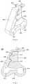
FIG. 3 is a structural schematic of an inter-pipe fixing member; -
FIG. 4 is a sectional view of the inter-pipe fixing member; -
FIG. 5 is a structural schematic of a connecting pipeline and the evaporator as shown inFIG. 1 ; -
FIG. 6 is another structural schematic of the connecting pipeline and the evaporator as shown inFIG. 1 ; -
FIG. 7 is another structural schematic of the connecting pipeline and the evaporator as shown inFIG. 1 ; -
FIG. 8 is another structural schematic of the connecting pipeline and the evaporator as shown inFIG. 1 ; and -
FIG. 9 is another structural schematic of the connecting pipeline and the evaporator as shown inFIG. 1 . -
FIG. 1 illustrates the structure of anevaporator 200 with aninter-pipe fixing member 400 according to an embodiment of this invention.FIG. 2 is a sectional view of theevaporator 200 shown inFIG. 1 . Theinter-pipe fixing member 400 comprises afixing portion 401 with at least twofixing grooves 411 configured to adapt to pipelines, and the at least twofixing grooves 411 are adapted to different pipelines and/or different sections of the same pipeline. This embodiment of theinter-pipe fixing member 400 comprises afixing portion 401 having at least twofixing grooves 411, the at least twofixing grooves 411 are adapted to different pipelines and/or different sections of the same pipeline, thus ensuring the fixation between different pipelines and/or different sections of the same pipeline. When applied to theevaporator 200, it maintains a certain distance between the pipelines of theevaporator 200 without collisions. As shown inFIG. 3 , a front wall of thefixing portion 401 has twofixing grooves 411 opening upwards and forwards, and the twofixing grooves 411 are spaced apart from each other along a vertical direction, to allow the pipeline to be threaded through thefixing grooves 411. - In some embodiments, the
inter-pipe fixing member 400 further comprises a movingpart 402 and aninsertion part 403. Themoving part 402 is movably connected to thefixing portion 401. Theinsertion part 403 is connecting with themoving part 402 and movably connected to thefixing portion 401, so that when the pipelines are inserted into thefixing grooves 411, pulling theinsertion part 403 can bring themoving part 402 closer to thefixing portion 401, thereby securing theinter-pipe fixing member 400 with the pipelines. Specifically, thefixing portion 401 is further provided with aninsertion port 412 into which theinsertion part 403 is inserted. The part of theinsertion part 403 that protrudes out of theinsertion port 412 is further provided with aninsertion protrusion 430 to further ensure the stable fixing of theinter-pipe fixing member 400 with the pipelines. As shown inFIG. 3 , thefixing grooves 411 are opened in a left-and-right direction, and theinsertion port 412 is opened in a front-and-back direction. In the application of this embodiment of theinter-pipe fixing member 400, theinsertion part 403 can not be inserted into theinsertion port 412, and themoving part 402 is far away from thefixing portion 401, and each pipeline is separately inserted into thecorresponding fixing groove 411, then themoving part 402 is rotated to approach thefixing portion 401, and theinsertion part 403 is inserted into theinsertion port 412 and tightened to secure theinter-pipe fixing member 400 with the pipelines. Alternatively, theinsertion part 403 can be initially inserted into theinsertion port 412 but not tightened, and after each pipeline is inserted into itscorresponding fixing groove 411, then tightened. This embodiment of theinter-pipe fixing member 400 comprises thefixing portion 401, the movingpart 402, and theinsertion part 403, and theinter-pipe fixing member 400 adopts a zip-tie-like fastening manner, thus ensuring the pipelines do not easily detach, maintaining the tightness and stability of the pipeline installation. The entire structure of theinter-pipe fixing member 400 is simple, easy to process and shape, and convenient for assembly with pipelines. - Furthermore, the size of each
fixing groove 411 satisfies the requirement for an interference fit with the corresponding pipeline. For instance, an inner diameter of thefixing groove 411 is 0.1mm smaller than an outer diameter of the corresponding pipeline, thereby ensuring a secure fit and preventing movement of the pipeline within thefixing groove 411. - As shown in
FIG. 1 , this embodiment of theevaporator 200 comprises an evaporator body, a connecting pipeline, and theinter-pipe fixing member 400. The evaporator body comprisesmultiple fins 201 and acoiled pipeline 202 bent and threaded through themultiple fins 201. The coiledpipeline 202 has a refrigerant inlet and a refrigerant outlet; the connecting pipeline is defined between a capillary tube and the refrigerant inlet. The aforementionedinter-pipe fixing member 400 is connected with the connecting pipeline via the fixinggrooves 411, thereby reducing the noise caused by pipelines resonance during the operation of theevaporator 200. The connecting pipeline can be a conventional transition pipe or adopt the structure as shown inFIG. 5 . - In some embodiments, the
inter-pipe fixing member 400 can be an integrally formed flexible structure, or at least partially a flexible structure. The flexible part of theinter-pipe fixing member 400 can be the part of theinter-pipe fixing member 400 that contacts the pipelines, defined with a flexible structure. The material for the flexible structure of theinter-pipe fixing member 400 can be TPE, rubber, or silicone. For example, theinter-pipe fixing member 400 can be integrally formed using TPE material with a hardness of HS (A) 35-65. Eachevaporator 200 is equipped with twointer-pipe fixing members 400. -
FIG. 3 is a structural schematic of theinter-pipe fixing member 400.FIG. 4 is a sectional view of theinter-pipe fixing member 400. In some embodiments, the fixingportion 401 of theinter-pipe fixing member 400 comprises afirst fixing section 441 and asecond fixing section 442; thesecond fixing section 442 extends forward from the lower rear side of thefirst fixing section 441. The fixinggrooves 411 are defined on thefirst fixing section 441, thesecond fixing section 442, or at an intersection between the first and second fixingsections insertion port 412 is provided at an upper part of thefirst fixing section 441 of theinter-pipe fixing member 400; the movingpart 402 is connected to a front end of thesecond fixing section 442, thereby allowing the pipeline to be inserted into the fixinggroove 411, and then by rotating the movingpart 402 upwards, theinsertion part 403 is inserted into theinsertion port 412. - As shown in
FIG. 3 and 4 , a front wall of thefirst fixing section 441 is provided with at least two fixinggrooves 411 opening upwards and forwards, and the at least two fixinggrooves 411 are spaced apart from each other along the vertical direction. An upper wall of thesecond fixing section 442 is provided with one fixinggroove 411 opening backwards and upwards. An intersection between thefirst fixing section 441 and thesecond fixing section 442 is provided with one fixinggroove 411 opening upwards and forwards. By defining different orientations for the fixinggrooves 411 at different positions, further assurance is provided for the fixation of the pipelines within the fixinggrooves 411, and preventing the pipelines from detaching from the fixinggrooves 411. - In some embodiments, the moving
part 402 of theinter-pipe fixing member 400 has at least two dockingprotrusions 420 at the positions corresponding to the fixinggrooves 411 on the front wall of thefirst fixing section 441, thus when the movingpart 402 abuts against the fixingportion 401, thedocking protrusions 420 are received in therelative fixing grooves 411, thereby securing the position of the pipelines within the fixinggrooves 411. - Through the above innovative design, structurally, the
inter-pipe fixing member 400 can tightly cooperate with each pipeline, thereby preventing loosening and displacement during the transportation and use of the refrigerator, and meeting the requirements for stability. About materiality, theinter-pipe fixing member 400 is resistant to high temperatures, low temperatures, corrosion, and aging, and is tough and not prone to breakage. In installation, theinter-pipe fixing member 400 is easy to install, thereby saving installation time and labor costs. In manufacturing, theinter-pipe fixing member 400 is easy to form and process, and the position of the fixinggroove 411 is stable, thereby ensuring the pipeline does not easily detach and maintaining the stability of the pipeline gap. Additionally, all parts of theinter-pipe fixing member 400 in this embodiment are smooth without any special protrusions or grooves, thereby ensuring smooth and convenient installation. Furthermore, an entire outer contour of theinter-pipe fixing member 400 can be designed as a triangular structure composed of several smooth arcs, thereby making the entireinter-pipe fixing member 400 appear smooth and facilitating installation. -
FIG. 5 is a structural schematic of the connecting pipeline and theevaporator 200 as shown inFIG. 1 . As illustrated inFIG. 5 , the connecting pipeline of theevaporator 200 in this embodiment comprises afirst pipeline 301, asecond pipeline 302, and aninlet pipeline 203 connected in sequence, theinlet pipeline 203 is connected to the refrigerant inlet, and an inner diameter of thefirst pipeline 301 is larger than that of thesecond pipeline 302. The refrigerant outlet of theevaporator 200 is connected to anoutlet pipeline 204; theinter-pipe fixing member 400 is connected to at least two of thefirst pipeline 301,second pipeline 302,inlet pipeline 203, andoutlet pipeline 204 via at least two fixinggrooves 411, and each pipeline fits with therelative fixing groove 411 in an interference fit, thereby reducing the noise caused by pipelines resonance during the operation of theevaporator 200. By setting theinter-pipe fixing member 400, which is made of flexible material, theinter-pipe fixing member 400 is connecting with at least two of thefirst pipeline 301,second pipeline 302,inlet pipeline 203, andoutlet pipeline 204 via at least two fixinggrooves 411, thereby effectively reducing the noise caused by pipelines resonance during the operation of theevaporator 200. Due to the pipelines have a longer length, wrapping only one pipeline results in a higher modal frequency may make them prone to resonance. Therefore, it is considered to set theinter-pipe fixing member 400 to constrain multiple cantilevered pipelines, thereby achieving better noise reduction. Specifically, during the operation of theevaporator 200, the flow of the refrigerant between the pipelines of theevaporator 200 causes strong vibration of the pipelines of theevaporator 200, thus generating significant noise. If the pipelines collide, it will exacerbate the noise and also affect the performance of theevaporator 200 and create safety hazards. Theinter-pipe fixing member 400 acts as a clamp fixed between the relevant pipelines of theevaporator 200. By setting theinter-pipe fixing member 400, the relative positions of each pipeline of theevaporator 200 can be ensured, thereby preventing contact collisions, and reducing the noise during the operation of theevaporator 200 and enhancing safety performance. - In some embodiments of this invention, a length of the
first pipeline 301 of the connecting pipeline is 0.02m to 1.25m, preferably 0.02m to 0.9m. Experimental tests have shown that when the length of thefirst pipeline 301 is between 0.02m and 1.25m, especially between 0.02m and 0.9m, it effectively reduces noise. - An upstream portion of the
first pipeline 301 of the connecting pipeline in this embodiment is connected to a capillary tube (not shown); an inner diameter of thefirst pipeline 301 is 0.5-10mm, and a wall thickness is 0.2-3mm. The inner diameter of thefirst pipeline 301 is larger than that of the capillary tube. If the wall of thefirst pipeline 301 is too thin, the noise reduction effect is poor, but if the wall is too thick, it increases costs; if the inner diameter of thefirst pipeline 301 is too small, it might lead to other types of noise issues. Therefore, it is preferable to limit the inner diameter of thefirst pipeline 301 to 0.5-10mm and the wall thickness to 0.2-3mm. - In the process of resolving spray noise, the fixation technique between the
first pipeline 301, thesecond pipeline 302, and theinlet pipeline 203 of the connecting pipeline in this embodiment is strongly related to the noise reduction effect. If not designed properly, it may lead to low-frequency noise problems. To ensure consistency in the process, the connecting pipeline of this embodiment optimizes the connection manner between every two neighboring pipelines. In some embodiments, thefirst pipeline 301 is fixed to thesecond pipeline 302 either by welding or by being integrally drawn; similarly, thesecond pipeline 302 is fixed to theinlet pipeline 203 either by welding or by being integrally drawn.FIG. 6 illustrates another structural schematic of the connecting pipeline and theevaporator 200 as shown inFIG. 1 . InFIG. 6 , thesecond pipeline 302 is welded to both thefirst pipeline 301 and theinlet pipeline 203. To ensure a certain strength of the welding, an inlet end of thesecond pipeline 302 is inserted into thefirst pipeline 301, and an outlet end of thesecond pipeline 302 is inserted into theinlet pipeline 203. In some embodiments, a length of insertion of the inlet end of thesecond pipeline 302 into thefirst pipeline 301 is 10-30mm; similarly, a length of insertion of the outlet end of thesecond pipeline 302 into theinlet pipeline 203 is 10-30mm. Aninsertion part 320 is marked inFIG. 6. FIG. 7 illustrates another structural schematic of the connecting pipeline and theevaporator 200 as shown inFIG. 1 ;FIG. 8 is another structural schematic of the connecting pipeline and theevaporator 200 as shown inFIG. 1 ;FIG. 9 is another structural schematic of the connecting pipeline and theevaporator 200 as shown inFIG. 1 . InFIG.7 , thefirst pipeline 301 is fixed to thesecond pipeline 302 being integrally drawn, thesecond pipeline 302 is fixed to theinlet pipeline 203 by welding, the integrally drawing of thesecond pipeline 302 and thefirst pipeline 301 can reduce the fluid resistance of the refrigerant in the connection pipeline from coarse to fine, thus reducing the noise. InFIG.8 , thesecond pipeline 302 is welded to thefirst pipeline 301, while thesecond pipeline 302 and theinlet pipeline 203 are integrally drawn. The integral drawing of thesecond pipeline 302 with theinlet pipeline 203 reduces the fluid resistance when the refrigerant in the connecting pipeline transitions from coarse to fine, thereby reducing noise. InFIG. 9 , thesecond pipeline 302 is integrally drawn with both thefirst pipeline 301 and theinlet pipeline 203. - The
outlet pipeline 204 of theevaporator 200 in this embodiment is welded to a return pipe of the refrigerator (not shown), and theoutlet pipeline 204 is threaded through one of the fixinggrooves 411 of theinter-pipe fixing member 400. As shown inFIG. 1 , eachinter-pipe fixing member 400 is divided into three parts for modal constraints, constraining the upper, middle, and lower parts of the " S" shaped pipeline. After welding theoutlet pipeline 204 to the return pipe of the refrigerator, theoutlet pipeline 204 can be considered as a fixed constraint. By setting one of the fixinggrooves 411 of theinter-pipe fixing member 400 to thread theoutlet pipeline 204, theinter-pipe fixing member 400 can utilize the external force of the fixedoutlet pipeline 204 to fix the thinnerfirst pipeline 301 and thesecond pipeline 302, thereby suppressing the vertical vibration of the S-shaped connecting pipeline. - This embodiment of the
inter-pipe fixing member 400 is set in the area 45-55mm in front of and behind a diameter transition point between thefirst pipeline 301 and thesecond pipeline 302; and/or theinter-pipe fixing member 400 is set in the area 45-55mm in front of and behind a diameter transition point between thesecond pipeline 302 and theinlet pipeline 203. The locations suitable for installing theinter-pipe fixing member 400 are indicated with square brackets inFIGS. 6 and 7 . The choice of different positions for theinter-pipe fixing member 400 is crucial. The right position segment can effectively suppress pipeline vibration and change the pipeline mode, avoiding resonance. If theinter-pipe fixing member 400 is placed at the modal node position, it will have no effect, and if placed at some other positions, the vibration might be amplified. When the refrigerant in the pipelines of theevaporator 200 flows from thefirst pipeline 301 to thesecond pipeline 302, throttling occurs at the diameter transition point due to increased resistance, causing intense fluid vibration. Adding theinter-pipe fixing member 400 at this position segment has a good damping effect. When the refrigerant flows from thesecond pipeline 302 to theinlet pipeline 203, a spray phenomenon occurs at the diameter transition point, where the vibration is most intense, and adding theinter-pipe fixing member 400 in this position segment will have a good damping effect. - This embodiment of the invention further provides a refrigerator having the
aforementioned evaporator 200. The refrigerator of this embodiment includes a cabinet, a door (not shown), and a compression refrigeration system. An inner liner of the cabinet defines storage compartments. Depending on the preservation temperature, the storage compartments can be divided into refrigeration compartments, freezer compartments, and variable temperature compartments, among others. The compression refrigeration system includes a compressor, theaforementioned evaporator 200, a condenser, and a capillary tube, among others. Theevaporator 200 is used to provide cooling for the storage compartments. - In the description of this embodiment, it should be understood that the terms "up," "down," "front," "back," "left," "right," and similar directional or positional terms are based on the orientations or positions shown in the drawings. They are used only to facilitate the description of the invention and to simplify the explanation, rather than to indicate or imply that the apparatus or components must have a specific orientation, be constructed and operated in a specific orientation, and thus should not be construed as limiting the invention.
- The terms "first," "second," etc., are used only for descriptive purposes and should not be interpreted as indicating or implying relative importance or implicitly specifying the number of technical features indicated. Therefore, features labeled "first," "second," etc., can explicitly or implicitly include one or more of such features.
- It should be noted that if the embodiment of the invention involves directional indications (such as up, down, left, right, front, back), these indications are only used to explain the relative position relationships, motion situations, etc., of the components in a certain posture (as shown in the drawings). If this specific posture changes, then the directional indications will accordingly change.
- So far, it should be appreciated by those skilled in the art that while various exemplary embodiments of the invention have been shown and described in detail herein, many other variations or modifications which are consistent with the principles of this invention may be determined or derived directly from the disclosure of the present invention without departing from the spirit and scope of the invention. Accordingly, the scope of the invention should be understood and interpreted to cover all such other variations or modifications.
Claims (10)
- An inter-pipe fixing member, comprising:
a fixing portion defining at least two fixing grooves, wherein the fixing grooves are configured to adapt to pipelines, and the at least two fixing grooves are adapted to different pipelines, and/or the at least two fixing grooves are adapted to different sections of the same pipeline. - The inter-pipe fixing member according to claim 1, wherein the inter-pipe fixing member is an integrally formed flexible structure, or at least partially a flexible structure.
- The inter-pipe fixing member according to claim 1 or 2, further comprising:a moving part, movably connected to the fixing portion; andan insertion part, connecting with the moving part and movably connected to the fixing portion, such that the pipeline inserted into the fixing groove, and pulling the insertion part brings the moving part closer to the fixing portion to secure the inter-pipe fixing member with the pipeline.
- The inter-pipe fixing member according to claim 3, wherein the fixing portion is provided with an insertion port, into which the insertion part is inserted; a part of the insertion part protruding out of the insertion port is further provided with an insertion protrusion.
- The inter-pipe fixing member according to claim 3, wherein the fixing portion comprises a first fixing section and a second fixing section; the second fixing section extends forward from a lower rear side of the first fixing section; the fixing grooves are defined on the first fixing section, the second fixing section, or at an intersection between the first and second fixing sections.
- The inter-pipe fixing member according to claim 5, wherein a front wall of the first fixing section is provided with at least two fixing grooves opening upwards and forwards at intervals along a vertical direction; an upper wall of the second fixing section is provided with a fixing groove opening backwards and upwards; the intersection between the first and second fixing sections is provided with a fixing groove opening upwards and forwards.
- The inter-pipe fixing member according to claim 6, wherein the moving part above the fixing groove on the front wall of the first fixing section is formed with a docking protrusion, ensuring that when the moving part fits against the fixing portion, the docking protrusion cooperates inside the fixing groove.
- An evaporator, comprising:an evaporator body, with its coiled pipeline having a refrigerant inlet and a refrigerant outlet;a connecting pipeline defined between a capillary tube and the refrigerant inlet; andthe inter-pipe fixing member according to any one of claims 1-7, connected with the connecting pipeline via the fixing grooves, to reduce the noise caused by pipelines resonance during the operation of the evaporator.
- The evaporator according to claim 8, wherein the refrigerant outlet is connected to an outlet pipeline; the connecting pipeline comprises a first pipeline, a second pipeline, and an inlet pipeline connected in sequence, the inlet pipeline is connected to the refrigerant inlet, and an inner diameter of the first pipeline is larger than that of the second pipeline; the inter-pipe fixing member is connected with at least two of the first pipeline, second pipeline, inlet pipeline, and outlet pipeline via at least two fixing grooves, and the pipelines fit with the fixing grooves in an interference fit.
- A refrigerator, having the evaporator according to claim 8 or 9.
Applications Claiming Priority (2)
| Application Number | Priority Date | Filing Date | Title |
|---|---|---|---|
| CN202121705667.3U CN216114849U (en) | 2021-07-26 | 2021-07-26 | Intertube fixing piece, evaporator and refrigerator |
| PCT/CN2022/092478 WO2023005346A1 (en) | 2021-07-26 | 2022-05-12 | Inter-pipe fixing member, evaporator and refrigerator |
Publications (4)
| Publication Number | Publication Date |
|---|---|
| EP4379245A1 true EP4379245A1 (en) | 2024-06-05 |
| EP4379245A4 EP4379245A4 (en) | 2024-10-30 |
| EP4379245C0 EP4379245C0 (en) | 2025-12-03 |
| EP4379245B1 EP4379245B1 (en) | 2025-12-03 |
Family
ID=80723347
Family Applications (1)
| Application Number | Title | Priority Date | Filing Date |
|---|---|---|---|
| EP22847959.8A Active EP4379245B1 (en) | 2021-07-26 | 2022-05-12 | Inter-pipe fixing member, evaporator and refrigerator |
Country Status (5)
| Country | Link |
|---|---|
| US (1) | US12669195B2 (en) |
| EP (1) | EP4379245B1 (en) |
| CN (1) | CN216114849U (en) |
| AU (1) | AU2022317695B9 (en) |
| WO (1) | WO2023005346A1 (en) |
Families Citing this family (2)
| Publication number | Priority date | Publication date | Assignee | Title |
|---|---|---|---|---|
| CN216114849U (en) * | 2021-07-26 | 2022-03-22 | 合肥海尔电冰箱有限公司 | Intertube fixing piece, evaporator and refrigerator |
| CN115682469B (en) * | 2021-07-26 | 2026-01-09 | 合肥海尔电冰箱有限公司 | Evaporator connection pipes, evaporator and refrigerator |
Family Cites Families (24)
| Publication number | Priority date | Publication date | Assignee | Title |
|---|---|---|---|---|
| US4163372A (en) * | 1977-10-25 | 1979-08-07 | Carrier Corporation | Capillary retainer clip |
| US4408467A (en) * | 1981-11-23 | 1983-10-11 | Carrier Corporation | Noise suppressing feeder tube for a refrigerant circuit |
| US20050247827A1 (en) * | 2004-04-27 | 2005-11-10 | David Moher | Conduit securement clip |
| DE202006007921U1 (en) * | 2006-04-28 | 2007-08-30 | Liebherr-Hausgeräte Lienz Gmbh | Fridge and / or freezer |
| FR2915263A1 (en) * | 2007-04-18 | 2008-10-24 | Flowserve Polyvalves Sas Soc P | DEVICE FOR MAINTAINING CONDUITS OF BODY EVENTS OF VALVE TYPE VALVE VALVES. |
| ITMI20071419A1 (en) * | 2007-07-16 | 2009-01-17 | Ilpea Ind Spa | COOLING CIRCUIT |
| CN203273032U (en) * | 2013-04-28 | 2013-11-06 | 上海汽车集团股份有限公司 | Pipe clamp for electric vehicle power battery cooler pipes |
| CN103672174B (en) * | 2013-10-18 | 2016-03-30 | 浙江吉利控股集团有限公司 | A kind of pipe clamp of easy combination |
| AU2016200271A1 (en) * | 2014-08-01 | 2016-02-18 | Caldwell, Elissa MS | Clamp device |
| CN204254053U (en) * | 2014-11-07 | 2015-04-08 | 亚普汽车部件股份有限公司 | The built-in multidigit pipe clamp of a kind of plastic fuel tank |
| CN204612322U (en) * | 2015-03-06 | 2015-09-02 | 青岛海尔股份有限公司 | Pipeline fixing support and there is the refrigerator of this pipeline fixing support |
| CN108204479B (en) * | 2018-01-11 | 2024-02-09 | 珠海格力电器股份有限公司 | Pipeline fixing structure and air conditioner comprising same |
| CN207989893U (en) * | 2018-02-06 | 2018-10-19 | 珠海格力电器股份有限公司 | Pipeline fixing structure and air conditioner including same |
| CN109732265A (en) * | 2018-08-28 | 2019-05-10 | 广东志高暖通设备股份有限公司 | Copper pipe pipe clamp |
| CN210320535U (en) * | 2019-07-18 | 2020-04-14 | 宁波奥克斯电气股份有限公司 | Pipeline fixed block and air conditioner |
| CN110925495B (en) * | 2019-12-06 | 2021-11-16 | 吉利汽车研究院(宁波)有限公司 | Pipeline fixing device and vehicle with same |
| CN111089199A (en) * | 2019-12-12 | 2020-05-01 | 格力电器(合肥)有限公司 | Self-locking device |
| CN211372618U (en) * | 2019-12-30 | 2020-08-28 | Tcl空调器(中山)有限公司 | Air conditioner noise reduction structure and air conditioner |
| CN113944820B (en) * | 2020-06-30 | 2025-11-11 | 青岛海尔智能技术研发有限公司 | Vibration and noise reduction device and pipeline vibration and noise reduction structure |
| CN112283453B (en) * | 2020-09-15 | 2022-05-31 | 神龙汽车有限公司 | Vehicle-mounted air conditioner pipeline vibration reduction connecting structure and mounting method thereof |
| CN215260656U (en) * | 2021-04-21 | 2021-12-21 | 青岛海尔电冰箱有限公司 | Throttling pipeline vibration reduction fixing piece, refrigerating system and refrigerating electrical appliance |
| CN216114849U (en) * | 2021-07-26 | 2022-03-22 | 合肥海尔电冰箱有限公司 | Intertube fixing piece, evaporator and refrigerator |
| CN215763666U (en) * | 2021-08-11 | 2022-02-08 | 格力电器(合肥)有限公司 | Pipe clamp assembly and air conditioner |
| CN113819306A (en) * | 2021-09-29 | 2021-12-21 | 广西玉柴机器股份有限公司 | Spatial combined pipe clamp structure of engine |
-
2021
- 2021-07-26 CN CN202121705667.3U patent/CN216114849U/en active Active
-
2022
- 2022-05-12 WO PCT/CN2022/092478 patent/WO2023005346A1/en not_active Ceased
- 2022-05-12 US US18/290,701 patent/US12669195B2/en active Active
- 2022-05-12 EP EP22847959.8A patent/EP4379245B1/en active Active
- 2022-05-12 AU AU2022317695A patent/AU2022317695B9/en active Active
Also Published As
| Publication number | Publication date |
|---|---|
| AU2022317695B2 (en) | 2025-05-15 |
| CN216114849U (en) | 2022-03-22 |
| EP4379245C0 (en) | 2025-12-03 |
| AU2022317695B9 (en) | 2025-05-29 |
| US12669195B2 (en) | 2026-06-30 |
| WO2023005346A1 (en) | 2023-02-02 |
| AU2022317695A1 (en) | 2024-01-25 |
| US20250092965A1 (en) | 2025-03-20 |
| EP4379245A4 (en) | 2024-10-30 |
| EP4379245B1 (en) | 2025-12-03 |
Similar Documents
| Publication | Publication Date | Title |
|---|---|---|
| US20250092965A1 (en) | Inter-pipe fixing member, Evaporator, and Refrigerator | |
| EP4379246A1 (en) | Fixing clip and refrigerator | |
| WO2022121468A1 (en) | Support structure, pipeline assembly, outdoor unit, and air conditioner | |
| AU2022317931B2 (en) | Connecting pipeline of evaporator, evaporator and refrigerator | |
| CN116447372A (en) | Electronic expansion valves and refrigeration equipment | |
| CN216114791U (en) | Connecting pipeline of evaporator, evaporator and refrigerator | |
| BRPI1103019A2 (en) | connector for airtight compressors | |
| RU2468311C2 (en) | Heat exchanger and refrigerating device | |
| CN105180524A (en) | Connecting tube assembly and refrigerator | |
| CN223137315U (en) | An integrated three-way connector that is easy to install | |
| KR102269483B1 (en) | Connector for refrigerant pipe | |
| CN223941547U (en) | Steel pipe silencer for refrigeration equipment | |
| KR101391839B1 (en) | Refrigerant pipe fixing device of a air conditioner | |
| CN110017644A (en) | Refrigerator | |
| CN212179281U (en) | Condenser, air-conditioning system, and pipe joints | |
| KR200217614Y1 (en) | A accumulator of cooling equipment | |
| KR100701346B1 (en) | Heat exchanger | |
| CN107421012B (en) | Shock-proof pipe of air conditioning system and air conditioning system | |
| KR200238516Y1 (en) | Refrigerant pipe connecting structure of a refrigerator | |
| CN115371297A (en) | Flow guide device for condenser, condenser with flow guide device and refrigeration system | |
| CN107328484A (en) | Sensor fastening device, heat-exchanging component and air temperature modification equipment | |
| CN109708342A (en) | Pipe-line system and refrigerator with it | |
| KR20020035687A (en) | An expansion valve of heat exchange cycle | |
| KR20020080853A (en) | Refrigerant pipe connecting structure of a refrigerator and connecting method thereof | |
| KR19980014141U (en) | Hot pipe fixing structure of the refrigerator |
Legal Events
| Date | Code | Title | Description |
|---|---|---|---|
| STAA | Information on the status of an ep patent application or granted ep patent |
Free format text: STATUS: THE INTERNATIONAL PUBLICATION HAS BEEN MADE |
|
| PUAI | Public reference made under article 153(3) epc to a published international application that has entered the european phase |
Free format text: ORIGINAL CODE: 0009012 |
|
| STAA | Information on the status of an ep patent application or granted ep patent |
Free format text: STATUS: REQUEST FOR EXAMINATION WAS MADE |
|
| 17P | Request for examination filed |
Effective date: 20240115 |
|
| AK | Designated contracting states |
Kind code of ref document: A1 Designated state(s): AL AT BE BG CH CY CZ DE DK EE ES FI FR GB GR HR HU IE IS IT LI LT LU LV MC MK MT NL NO PL PT RO RS SE SI SK SM TR |
|
| A4 | Supplementary search report drawn up and despatched |
Effective date: 20240927 |
|
| DAV | Request for validation of the european patent (deleted) | ||
| DAX | Request for extension of the european patent (deleted) | ||
| RIC1 | Information provided on ipc code assigned before grant |
Ipc: F16L 55/035 20060101ALI20240923BHEP Ipc: F25D 11/00 20060101ALI20240923BHEP Ipc: F25B 39/02 20060101ALI20240923BHEP Ipc: F16L 3/10 20060101AFI20240923BHEP |
|
| GRAP | Despatch of communication of intention to grant a patent |
Free format text: ORIGINAL CODE: EPIDOSNIGR1 |
|
| STAA | Information on the status of an ep patent application or granted ep patent |
Free format text: STATUS: GRANT OF PATENT IS INTENDED |
|
| INTG | Intention to grant announced |
Effective date: 20250703 |
|
| GRAS | Grant fee paid |
Free format text: ORIGINAL CODE: EPIDOSNIGR3 |
|
| GRAA | (expected) grant |
Free format text: ORIGINAL CODE: 0009210 |
|
| STAA | Information on the status of an ep patent application or granted ep patent |
Free format text: STATUS: THE PATENT HAS BEEN GRANTED |
|
| AK | Designated contracting states |
Kind code of ref document: B1 Designated state(s): AL AT BE BG CH CY CZ DE DK EE ES FI FR GB GR HR HU IE IS IT LI LT LU LV MC MK MT NL NO PL PT RO RS SE SI SK SM TR |
|
| RAP3 | Party data changed (applicant data changed or rights of an application transferred) |
Owner name: HEFEI HAIER REFRIGERATOR CO., LTD Owner name: QINGDAO HAIER REFRIGERATOR CO., LTD. Owner name: HAIER SMART HOME CO., LTD. |
|
| REG | Reference to a national code |
Ref country code: CH Ref legal event code: F10 Free format text: ST27 STATUS EVENT CODE: U-0-0-F10-F00 (AS PROVIDED BY THE NATIONAL OFFICE) Effective date: 20251203 Ref country code: GB Ref legal event code: FG4D |
|
| REG | Reference to a national code |
Ref country code: DE Ref legal event code: R096 Ref document number: 602022026312 Country of ref document: DE |
|
| REG | Reference to a national code |
Ref country code: IE Ref legal event code: FG4D |
|
| U01 | Request for unitary effect filed |
Effective date: 20251219 |
|
| U07 | Unitary effect registered |
Designated state(s): AT BE BG DE DK EE FI FR IT LT LU LV MT NL PT RO SE SI Effective date: 20260105 |
|
| PG25 | Lapsed in a contracting state [announced via postgrant information from national office to epo] |
Ref country code: ES Free format text: LAPSE BECAUSE OF FAILURE TO SUBMIT A TRANSLATION OF THE DESCRIPTION OR TO PAY THE FEE WITHIN THE PRESCRIBED TIME-LIMIT Effective date: 20251203 |
|
| PG25 | Lapsed in a contracting state [announced via postgrant information from national office to epo] |
Ref country code: NO Free format text: LAPSE BECAUSE OF FAILURE TO SUBMIT A TRANSLATION OF THE DESCRIPTION OR TO PAY THE FEE WITHIN THE PRESCRIBED TIME-LIMIT Effective date: 20260303 |
|
| PG25 | Lapsed in a contracting state [announced via postgrant information from national office to epo] |
Ref country code: HR Free format text: LAPSE BECAUSE OF FAILURE TO SUBMIT A TRANSLATION OF THE DESCRIPTION OR TO PAY THE FEE WITHIN THE PRESCRIBED TIME-LIMIT Effective date: 20251203 |
|
| PG25 | Lapsed in a contracting state [announced via postgrant information from national office to epo] |
Ref country code: RS Free format text: LAPSE BECAUSE OF FAILURE TO SUBMIT A TRANSLATION OF THE DESCRIPTION OR TO PAY THE FEE WITHIN THE PRESCRIBED TIME-LIMIT Effective date: 20260303 |
|
| PG25 | Lapsed in a contracting state [announced via postgrant information from national office to epo] |
Ref country code: PL Free format text: LAPSE BECAUSE OF FAILURE TO SUBMIT A TRANSLATION OF THE DESCRIPTION OR TO PAY THE FEE WITHIN THE PRESCRIBED TIME-LIMIT Effective date: 20251203 |
|
| U20 | Renewal fee for the european patent with unitary effect paid |
Year of fee payment: 5 Effective date: 20260428 |
|
| PG25 | Lapsed in a contracting state [announced via postgrant information from national office to epo] |
Ref country code: SM Free format text: LAPSE BECAUSE OF FAILURE TO SUBMIT A TRANSLATION OF THE DESCRIPTION OR TO PAY THE FEE WITHIN THE PRESCRIBED TIME-LIMIT Effective date: 20251203 |
|
| PG25 | Lapsed in a contracting state [announced via postgrant information from national office to epo] |
Ref country code: IS Free format text: LAPSE BECAUSE OF FAILURE TO SUBMIT A TRANSLATION OF THE DESCRIPTION OR TO PAY THE FEE WITHIN THE PRESCRIBED TIME-LIMIT Effective date: 20260403 |
|
| PG25 | Lapsed in a contracting state [announced via postgrant information from national office to epo] |
Ref country code: CZ Free format text: LAPSE BECAUSE OF FAILURE TO SUBMIT A TRANSLATION OF THE DESCRIPTION OR TO PAY THE FEE WITHIN THE PRESCRIBED TIME-LIMIT Effective date: 20251203 |
|
| PG25 | Lapsed in a contracting state [announced via postgrant information from national office to epo] |
Ref country code: SK Free format text: LAPSE BECAUSE OF FAILURE TO SUBMIT A TRANSLATION OF THE DESCRIPTION OR TO PAY THE FEE WITHIN THE PRESCRIBED TIME-LIMIT Effective date: 20251203 |