EP4379237A1 - Speed reducer - Google Patents
Speed reducer Download PDFInfo
- Publication number
- EP4379237A1 EP4379237A1 EP22849527.1A EP22849527A EP4379237A1 EP 4379237 A1 EP4379237 A1 EP 4379237A1 EP 22849527 A EP22849527 A EP 22849527A EP 4379237 A1 EP4379237 A1 EP 4379237A1
- Authority
- EP
- European Patent Office
- Prior art keywords
- axial direction
- speed reducer
- bearings
- carrier
- planetary gear
- Prior art date
- Legal status (The legal status is an assumption and is not a legal conclusion. Google has not performed a legal analysis and makes no representation as to the accuracy of the status listed.)
- Pending
Links
- 239000003638 chemical reducing agent Substances 0.000 title claims abstract description 86
- 230000008878 coupling Effects 0.000 claims description 34
- 238000010168 coupling process Methods 0.000 claims description 34
- 238000005859 coupling reaction Methods 0.000 claims description 34
- 230000004048 modification Effects 0.000 description 51
- 238000012986 modification Methods 0.000 description 51
- 238000000034 method Methods 0.000 description 6
- 230000002093 peripheral effect Effects 0.000 description 4
- 238000003780 insertion Methods 0.000 description 1
- 230000037431 insertion Effects 0.000 description 1
- 230000002452 interceptive effect Effects 0.000 description 1
Images








Classifications
-
- H—ELECTRICITY
- H02—GENERATION; CONVERSION OR DISTRIBUTION OF ELECTRIC POWER
- H02K—DYNAMO-ELECTRIC MACHINES
- H02K7/00—Arrangements for handling mechanical energy structurally associated with dynamo-electric machines, e.g. structural association with mechanical driving motors or auxiliary dynamo-electric machines
- H02K7/10—Structural association with clutches, brakes, gears, pulleys or mechanical starters
- H02K7/116—Structural association with clutches, brakes, gears, pulleys or mechanical starters with gears
-
- F—MECHANICAL ENGINEERING; LIGHTING; HEATING; WEAPONS; BLASTING
- F16—ENGINEERING ELEMENTS AND UNITS; GENERAL MEASURES FOR PRODUCING AND MAINTAINING EFFECTIVE FUNCTIONING OF MACHINES OR INSTALLATIONS; THERMAL INSULATION IN GENERAL
- F16H—GEARING
- F16H1/00—Toothed gearings for conveying rotary motion
- F16H1/28—Toothed gearings for conveying rotary motion with gears having orbital motion
-
- F—MECHANICAL ENGINEERING; LIGHTING; HEATING; WEAPONS; BLASTING
- F16—ENGINEERING ELEMENTS AND UNITS; GENERAL MEASURES FOR PRODUCING AND MAINTAINING EFFECTIVE FUNCTIONING OF MACHINES OR INSTALLATIONS; THERMAL INSULATION IN GENERAL
- F16H—GEARING
- F16H57/00—General details of gearing
- F16H57/02—Gearboxes; Mounting gearing therein
- F16H57/021—Shaft support structures, e.g. partition walls, bearing eyes, casing walls or covers with bearings
- F16H57/022—Adjustment of gear shafts or bearings
-
- F—MECHANICAL ENGINEERING; LIGHTING; HEATING; WEAPONS; BLASTING
- F16—ENGINEERING ELEMENTS AND UNITS; GENERAL MEASURES FOR PRODUCING AND MAINTAINING EFFECTIVE FUNCTIONING OF MACHINES OR INSTALLATIONS; THERMAL INSULATION IN GENERAL
- F16H—GEARING
- F16H57/00—General details of gearing
- F16H57/12—Arrangements for adjusting or for taking-up backlash not provided for elsewhere
-
- F—MECHANICAL ENGINEERING; LIGHTING; HEATING; WEAPONS; BLASTING
- F16—ENGINEERING ELEMENTS AND UNITS; GENERAL MEASURES FOR PRODUCING AND MAINTAINING EFFECTIVE FUNCTIONING OF MACHINES OR INSTALLATIONS; THERMAL INSULATION IN GENERAL
- F16H—GEARING
- F16H1/00—Toothed gearings for conveying rotary motion
- F16H1/28—Toothed gearings for conveying rotary motion with gears having orbital motion
- F16H1/46—Systems consisting of a plurality of gear trains each with orbital gears, i.e. systems having three or more central gears
-
- F—MECHANICAL ENGINEERING; LIGHTING; HEATING; WEAPONS; BLASTING
- F16—ENGINEERING ELEMENTS AND UNITS; GENERAL MEASURES FOR PRODUCING AND MAINTAINING EFFECTIVE FUNCTIONING OF MACHINES OR INSTALLATIONS; THERMAL INSULATION IN GENERAL
- F16H—GEARING
- F16H1/00—Toothed gearings for conveying rotary motion
- F16H1/28—Toothed gearings for conveying rotary motion with gears having orbital motion
- F16H2001/2881—Toothed gearings for conveying rotary motion with gears having orbital motion comprising two axially spaced central gears, i.e. ring or sun gear, engaged by at least one common orbital gear wherein one of the central gears is forming the output
-
- F—MECHANICAL ENGINEERING; LIGHTING; HEATING; WEAPONS; BLASTING
- F16—ENGINEERING ELEMENTS AND UNITS; GENERAL MEASURES FOR PRODUCING AND MAINTAINING EFFECTIVE FUNCTIONING OF MACHINES OR INSTALLATIONS; THERMAL INSULATION IN GENERAL
- F16H—GEARING
- F16H55/00—Elements with teeth or friction surfaces for conveying motion; Worms, pulleys or sheaves for gearing mechanisms
- F16H55/02—Toothed members; Worms
- F16H55/17—Toothed wheels
- F16H2055/176—Ring gears with inner teeth
-
- F—MECHANICAL ENGINEERING; LIGHTING; HEATING; WEAPONS; BLASTING
- F16—ENGINEERING ELEMENTS AND UNITS; GENERAL MEASURES FOR PRODUCING AND MAINTAINING EFFECTIVE FUNCTIONING OF MACHINES OR INSTALLATIONS; THERMAL INSULATION IN GENERAL
- F16H—GEARING
- F16H57/00—General details of gearing
- F16H57/02—Gearboxes; Mounting gearing therein
- F16H57/021—Shaft support structures, e.g. partition walls, bearing eyes, casing walls or covers with bearings
- F16H57/022—Adjustment of gear shafts or bearings
- F16H2057/0221—Axial adjustment
-
- F—MECHANICAL ENGINEERING; LIGHTING; HEATING; WEAPONS; BLASTING
- F16—ENGINEERING ELEMENTS AND UNITS; GENERAL MEASURES FOR PRODUCING AND MAINTAINING EFFECTIVE FUNCTIONING OF MACHINES OR INSTALLATIONS; THERMAL INSULATION IN GENERAL
- F16H—GEARING
- F16H57/00—General details of gearing
- F16H57/08—General details of gearing of gearings with members having orbital motion
- F16H2057/085—Bearings for orbital gears
-
- F—MECHANICAL ENGINEERING; LIGHTING; HEATING; WEAPONS; BLASTING
- F16—ENGINEERING ELEMENTS AND UNITS; GENERAL MEASURES FOR PRODUCING AND MAINTAINING EFFECTIVE FUNCTIONING OF MACHINES OR INSTALLATIONS; THERMAL INSULATION IN GENERAL
- F16H—GEARING
- F16H57/00—General details of gearing
- F16H57/12—Arrangements for adjusting or for taking-up backlash not provided for elsewhere
- F16H2057/125—Adjustment of backlash during mounting or assembly of gearing
-
- F—MECHANICAL ENGINEERING; LIGHTING; HEATING; WEAPONS; BLASTING
- F16—ENGINEERING ELEMENTS AND UNITS; GENERAL MEASURES FOR PRODUCING AND MAINTAINING EFFECTIVE FUNCTIONING OF MACHINES OR INSTALLATIONS; THERMAL INSULATION IN GENERAL
- F16H—GEARING
- F16H57/00—General details of gearing
- F16H57/08—General details of gearing of gearings with members having orbital motion
- F16H57/082—Planet carriers
Definitions
- the present invention relates to a speed reducer.
- the size of the bearings at the output side may be made smaller than the inner diameter of the internal gear or the outer diameter of the plurality of planetary gears.
- the two bearings have different sizes, the rigidity cannot be ensured, and pressure application to the planetary gears may be difficult to adjust.
- a speed reducer capable of improving rigidity is to be provided.
- a speed reducer in one aspect, includes a sun gear, an internal gear, and a planetary gear meshing with the sun gear and the internal gear.
- the speed reducer includes two bearings disposed to sandwich the planetary gear in an axial direction. At least one of the two bearings is pressed against the planetary gear in an axial direction by an engaging member.
- rigidity can be improved.
- each drawing may illustrate a coordinate system.
- an extending direction of an output shaft 98 to be described below is defined as an axial direction and a rotation direction of the output shaft 98 is defined as a circumferential direction.
- FIG. 1 is a perspective view illustrating an example of a drive device according to a first embodiment.
- the drive device 1 according to the present embodiment includes a speed reducer 2 and a motor 9.
- the speed reducer 2 includes a coupling part 10 and a main body part 20.
- the side of the location of the motor 9 may be referred to as a negative direction side in the axial direction
- the side of the location of the speed reducer 2 may be referred to as a positive direction side in the axial direction.
- the main body part 20 of the speed reducer 2 is coupled to the motor 9 via the coupling part 10. More specifically, the coupling part 10 is fixed to the motor 9 by a plurality of first screws 91 illustrated in FIGS. 1 to 3 , and is fixed to the main body part 20 by a plurality of second screws 92.
- FIG. 2 is a perspective view illustrating an example of the speed reducer according to the first embodiment.
- FIG. 3 is a side cross-sectional view illustrating an example of the speed reducer according to the first embodiment.
- FIG. 3 illustrates a cross section cut along the plane PA illustrated in FIG. 2 . Note that, in the following description, four first screws 91 may be indicated as first screws 91a to 91d to distinguish them from each other, and eight second screws 92 may be indicated as second screws 92a to 92h to distinguish them from each other.
- the first screws 91 are inserted into through holes 19 formed in the coupling part 10 and fixed to screw grooves 99 formed in the motor 9 shown in FIG. 1 .
- the second screws 92 are inserted into through holes 1u formed in the coupling part 10 and are fixed to the screw grooves 2v formed in the main body part 20.
- through holes 29 are formed in the main body part 20 at a position facing the through holes 19 of the coupling part 10 in the axial direction as illustrated in FIG. 3 .
- a size (length in the axial direction) L3 of the first screw 91 is smaller than an interval I1 between the through hole 19 of the coupling part 10 and the through hole 29 of the main body part 20 in the axial direction as illustrated in FIG. 3 , for example.
- the length of the interval I1 is 5 mm
- the length L3 of the first screw 91 is 16 mm.
- the coupling part 10 and the main body part 20 are fixed to each other after the four first screws 91 are inserted into the through holes 19 of the coupling part 10, for example.
- the through holes 29 are formed such that the positions of the through holes 29 in a radial direction and the circumferential direction are substantially the same as the positions of the through holes 19 in the radial direction and the circumferential direction.
- the first screws 91 can be fastened after the coupling part 10 and the main body part 20 are fixed to each other by inserting a tool T00 into a through hole 29 from the positive direction side in the axial direction as illustrated in FIG. 3 .
- the length in the axial direction can be reduced, particularly in a speed reducer 2 with only one planetary gear stage.
- the speed reducer 2 can be fixed to the motor 9 without using a special tool or going through a special process.
- an inner diameter R1 of the through hole 29 is, for example, greater than an outer diameter of the tool T00 and smaller than an inner diameter R2 of the through hole 19.
- FIG. 4 is a cross-sectional perspective view illustrating an example of the drive device according to the first embodiment.
- FIG. 1 illustrates a cross section cut along the line A-A in FIG. 4 .
- An adapter 89 illustrated in FIG. 4 rotatably connects an output shaft 98 of the motor 9 to a sun gear 84.
- a driving force of the motor 9 is transmitted to the sun gear 84 via the output shaft 98 and the adapter 89.
- the adapter 89 is disposed, for example, on an inner peripheral side of the coupling part 10 as illustrated in FIG. 4 .
- the output shaft of the motor may be coupled to the sun gear 84, for example, in the form of being press-fitted into a radially inner side of the sun gear 84.
- the output shaft of the motor and the sun gear 84 may be integrally formed by gear-cutting an end portion of the output shaft in the axial direction.
- FIG. 5 is another side cross-sectional view illustrating an example of the speed reducer according to the first embodiment.
- FIG. 5 illustrates a cross section cut along the line A-A in FIG. 1 .
- the planetary gear 40 is rotatably held by the carrier 30 via a planetary shaft 48 as illustrated in FIG. 5 .
- the planetary gear 40 is rotatably supported by the planetary shaft 48 via a bearing 41 as illustrated in FIG. 5 .
- a roller bearing is used as the bearing 41.
- the bearing 41 may be, for example, a full roller bearing with no cage.
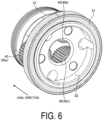
- FIG. 6 is a view illustrating an example of the carrier equipped with the bearing according to the first embodiment.
- three planetary gears 40 are held by the carrier 30. Note that, the three planetary gears 40 may be described below as a planetary gear 40a to a planetary gear 40c to distinguish them from each other.
- the carrier 30 of the present embodiment includes a first member 31 and a second member 32 as illustrated in FIG. 6 .
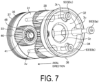
- the first member 31 and the second member 32 are assembled to face each other in the axial direction as illustrated in FIG. 7.
- FIG. 7 is an exploded perspective view illustrating an example of the carrier according to the first embodiment.
- the first member 31 includes an outer ring 33 and a coupling surface 37 as illustrated in FIG. 7 .
- the second member 32 includes an outer ring 34 and a strut 38.
- the strut 38 is formed at a position adjacent to the planetary gears 40 in the circumferential direction as illustrated in FIG. 7 .
- the three planetary gears 40 in the present embodiment are held by the carrier 30 after the bearing 51 is mounted at the carrier 30. More specifically, the bearing 51 is mounted at the outer ring 34 of the second member 32 of the carrier 30 from the positive direction side in the axial direction. The first member 31 and the second member 32 are assembled after the bearing 51 is mounted at the second member 32. According to this configuration, the bearing 51 can be formed such that the outer diameter of the bearing 51 is positioned at the outer diameter side of the tooth tips of the planetary gears 40 in the radial direction.
- a through hole 3s and a screw groove 3v are formed in the first member 31, and through holes 3u, 3t, and 3z are formed in the second member 32 as illustrated in FIG. 5 .
- the through hole 3u is formed to pass through the strut 38 in the axial direction as illustrated in FIG. 7 .
- the planetary shafts 48 illustrated in FIG. 5 are inserted into the through holes 3s and 3t.
- the first member 31 and the second member 32 are positioned by the planetary shafts 48 to be assembled.
- An internal gear 24 is formed at the inner peripheral side of the main body part 20 as illustrated FIG. 5 .
- the planetary gears 40 rotating in conjunction with the sun gear 84 mesh with the internal gear 24 to revolve along the internal gear 24.
- the carrier 30 holding the planetary gears 40 via the planetary shafts 48 rotates in conjunction with the revolution of the planetary gears 40.
- the internal gear 24 in the present embodiment is fixed to the main body part 20 and does not rotate regardless of the revolution or rotation of the planetary gears 40.
- An external screw 35 is formed on the outer ring 33 of the first member 31, and a flange 36 is formed on the outer ring 34 of the second member 32 as illustrated in FIG. 7 .
- a nut 53 illustrated in FIG. 5 is mounted at the external screw 35.
- a bearing 51 mounted from the positive direction side in the axial direction is supported by the flange 36.
- the first member 31 and the second member 32 are fixed by third screws 93 as illustrated in FIG. 7 .
- the three third screws 93a to 93c are inserted into the through holes 3u formed in the second member 32 and are respectively fixed to the screw grooves 3v formed in the first member 31.
- the third screws 93 are an example of a locking member.
- the carrier 30 of the present embodiment is constituted by two members, namely, the first member 31 and the second member 32 as described above.
- the first member 31 and the second member 32 are positioned by the planetary shafts 48. According to this configuration, workability and assemblability of the carrier 30 are improved, and a decrease in the accuracy of the planetary gears 40 can be curbed.
- FIG. 8 is an exploded perspective view illustrating an example of a speed reducer assembly process according to the first embodiment.
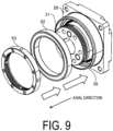
- a portion including the external screw 35 of the first member 31 of the carrier 30 inserted into the main body part 20 protrudes further toward the positive direction side in the axial direction than the end portion of the main body part 20 at the positive direction side in the axial direction as illustrated in FIG. 9.
- FIG. 9 is an exploded perspective view illustrating an example of the speed reducer assembly process according to the first embodiment. Then, a bearing 52 and a nut 53 are further attached to the first member 31 of the carrier 30 inserted into the main body part 20 as indicated by the arrows in FIG. 9 .
- the bearing 52 is attached to the outer ring 33 of the first member 31 from the positive direction side in the axial direction.
- the bearings 51 and 52 are formed to have substantially the same size in the radial direction.
- the nut 53 is further mounted at the carrier 30 with the bearing 52 mounted. Note that the nut 35 is an example of an engaging member.
- the carrier 30 holding the planetary gears 40 and further having the bearings 51 and 52 and the nut 53 mounted may be referred to as a revolving part 50.
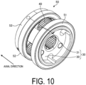
- FIG. 10 is a perspective view illustrating an example of the revolving part according to the first embodiment.
- the planetary gears 40 are interposed between the bearing 51 and the bearing 52 in the axial direction as illustrated in FIG. 10 .
- the bearing 52 is mounted at the carrier 30 such that the internal gear 24 of the main body part 20 is interposed between the bearing 52 and the bearing 51 in the axial direction.
- the nut 53 presses the bearings 51 and 52 toward the negative direction side in the axial direction.
- the bearing 51 positioned at the input side (the negative direction side in the axial direction) is pressed against a receiving part 25 of the main body part 20 and the flange 36 of the second member 32 by the nut 53.
- the bearing 52 positioned at the output side (the positive direction side in the axial direction) is pressed by the nut 53 against the planetary gears 40, the receiving part 26 of the main body part 20, and the internal gear 24.
- the inner rings of the two bearings 51 and 52 are in contact with the internal gear 24 in the axial direction and are both supported by the main body part 20 in the radial direction. As a result, the occurrence of warping or the like due to a load caused by rotation of the carrier 30 is curbed.
- a part of the coupling part 10 at the positive direction side in the axial direction is positioned further at the positive direction side in the axial direction than the end portion of the bearing 51 at the negative direction side in the axial direction. That is, the receiving part 15 formed in the coupling part 10 faces the bearing 51 in the radial direction as illustrated in FIG. 5 .
- a part of the bearing 51 is further supported by the receiving part 15 of the coupling part 10 in the axial direction and the radial direction. According to this configuration, loads of the carrier 30 are dispersed to the coupling part 10 in addition to the main body part 20.
- grooves 3r for fixing a driving target are formed in the coupling surface 37 of the first member as illustrated in FIG. 4 .
- a driving target such as a robot arm is fixed to the first member 31 by a screw or the like, to rotate in conjunction with the carrier 30.
- a spigot part 21 to be coupled to a driving object or the like is formed on the outer peripheral surface of the main body part 20 as illustrated in FIGS. 4 and 5 .
- the bearings 51 and 52 are assembled to sandwich the internal gear 24 in the axial direction in the present embodiment.
- the outer diameter of the bearing 52 at the output side (the positive direction side in the axial direction) can be made the same as the outer diameter of the bearing 51 at the input side (the positive direction side in the axial direction).
- the bearing 51 can tolerate a sufficient amount of load.
- the amount of pressure applied to the bearings 51 and 52 can be appropriately adjusted by adjusting the degree of tightening by the nut 53, tilting of the gears can be reduced, backlash can be reduced, and the durability of the gears can be improved.
- the carrier 30 includes the second member 32 with the bearing 51 mounted and the first member 31 with the bearing 52 mounted. For this reason, the assemblability and processability of the carrier 30 supported at both sides by the two bearings can be improved. In addition, since the first member 31 and the second member 32 are reinforced by the third screw 93, loosening of the first member 31 and the second member 32 in the axial direction is curbed.
- the speed reducer 2 includes the sun gear 84, the internal gear 24, and the planetary gears 40 meshing with the sun gear 84 and the internal gear 24.
- the speed reducer 2 includes the two bearings 51 and 52 disposed to sandwich the planetary gears 40 in the axial direction. At least one of the two bearings 51 and 52 is pressed against the planetary gears 40 in the axial direction by the engaging member 53. Furthermore, the two bearings 51 and 52 have the same size in the radial direction. According to this configuration, since the carrier 30 holding the planetary gears 40 is supported at both sides by the two bearings 51 and 52 having substantially the same size in the radial direction, the rigidity of the speed reducer 2 can be improved. In addition, since the amount of pressure applied to the bearings 51 and 52 varies depending on the degree of tightening of the nut 53, the amount of pressure can be easily adjusted.
- the embodiment is not limited to such configurations.
- the strut 38 may be formed on the first member 31 of the carrier 30, instead of the second member 32.
- the number of struts 38 is not limited to that described above and may be different from the number of planetary gears 40 included in the carrier 30.
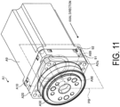
- FIG. 11 is a perspective view illustrating an example of a speed reducer according to a first modification.
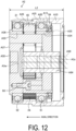
- FIG. 12 is a side cross-sectional view illustrating an example of the speed reducer according to the first modification.
- FIG. 13 is a cross-sectional perspective view illustrating an example of a revolving part according to the first modification.
- FIG. 14 is a perspective view illustrating an example of a carrier according to the first modification.
- FIGS. 12 and 13 illustrates a cross section cut along the plane PB illustrated in FIG. 11 .
- a drive device A1 in the first modification includes a motor A9 and a speed reducer A2 as illustrated in FIG. 11 .
- a carrier A30 in the first modification includes a first member A31 and a second member A32 as illustrated in FIG. 14 .
- a flange A36 is formed on an outer ring A33 of the first member A31
- an external screw A35 is formed on an outer ring A34 of the second member A32.
- the first member A31 further includes a coupling surface A37, and a recessed portion A3w is further formed at a central portion of the first member A31 in the radial direction. Note that, although FIG.
- FIG 14 illustrates the carrier A30 with no bearing 52 mounted, when a speed reducer A2 is assembled, the bearing 52 is attached to the first member A31, and thus the second member A32 is fixed to the first member A31 such that the planetary gears 40 are held between the first member A31 and the second member A32.
- the bearing 52 is mounted at the carrier A30 before the bearing 51 is mounted.
- the bearing 52 is mounted at the outer ring A33 of the first member A31 from the negative direction side in the axial direction. Then, the first member A31 and the second member A32 are combined to hold the three planetary gears 40.
- the carrier A30 with the bearing 52 mounted is inserted into the main body part A20 from the positive direction side in the axial direction. Then, the bearing 51 and the nut 54 are further mounted at the carrier A30 inserted into the main body part A20 from the negative direction side in the axial direction as illustrated in FIG. 13 .
- the bearing 52 is supported in the radial direction by a receiving part A26 formed in the main body part A20.
- the bearing 51 is supported in the radial direction by a receiving part A25 formed in the main body part A20 and a receiving part A15 formed in the coupling part A10. Note that, in FIG. 13 , illustration of an internal gear A24 sandwiched between the bearing 51 and the bearing 52 in the axial direction is omitted.
- an output shaft A98 of a motor A9 illustrated in FIG. 11 is press-fitted to the radially inner side of a sun gear A84 as illustrated in FIG. 12 .
- the sun gear A84 is inserted into a through hole A3z of the carrier A30 and is supported by the recessed portion A3w.
- a driving force of the motor A9 is transmitted to the planetary gears 40 via the sun gear A84.
- the first screws 91 inserted into the coupling part A10 are fixed to screw grooves A99 formed in the motor A9 as illustrated in FIG. 11 .
- a thickness (length in the axial direction) L2 of the speed reducer A2 illustrated in FIG. 12 can be made smaller than a thickness L1 of the speed reducer 2 illustrated in FIG. 5 while the length of the sun gear A84 is maintained.
- the nut 54 protrudes toward the coupling part A10 side in the axial direction as illustrated in FIG. 12 .
- the coupling part A10 is fixed to the motor A9, the nut 54 is not visible. According to this configuration, the nut 54 can be prevented from being subjected to an unintended operation such as disassembly after the speed reducer A2 has been assembled.
- the length of the speed reducer A2 in the axial direction can be reduced.
- the output shaft A98 is desirably inserted into the sun gear A84. According to this configuration, the length of the speed reducer A2 in the axial direction can be further reduced while maintaining the length of the sun gear A84 in the axial direction.
- a through hole A2q for insertion of the second screw 92 may be formed in the main body part A20 instead of a screw groove 2v in the first embodiment as illustrated in FIG. 11 . Since the thicknesses (lengths in the axial direction) of the main body part A20 can be reduced due to this configuration as will be described later, the length of the speed reducer A2 in the axial direction can be further reduced.
- each member such as each of the planetary gears 40 described in the first embodiment may be attached with the term "first” such as in the case of "first planetary gear 40".
- FIG. 15 is a cross-sectional perspective view illustrating an example of the speed reducer according to the second embodiment.
- the speed reducer B2 according to the second embodiment further includes a second main body part B0 between a coupling part B10 and a first main body part 20 in the axial direction as illustrated in FIG. 15 .
- a second screw 92 is further inserted into, for example, a through hole (not illustrated) formed in the second main body part B0.
- the coupling part B 10 the second main body part B0, and the first main body part B20 are fixed to each other.
- the bearing 51 may be supported by a receiving part B5 formed in the second main body part B0 as illustrated in FIG. 15 , instead of the receiving part 15 of the coupling part 10 in the first embodiment.
- the speed reducer B2 further includes a second carrier 60 holding the three second planetary gears 70 in addition to the revolving part 50 including a first carrier 30 holding the first planetary gears 40.
- a second sun gear 85 is inserted into the second carrier 60 from the negative direction side in the axial direction as illustrated in FIG. 15 .
- the second planetary gears 70 rotate in conjunction with the second sun gear 85.
- an adapter B89 is connected to the second sun gear 85.
- the adapter B89 is mounted at an output shaft of a motor not illustrated. Thus, a driving force of the motor is transmitted to the second sun gear 85 via the adapter B89.
- a second internal gear B7 is formed at the inner peripheral side of the second main body part B0.
- the second planetary gears 70 rotate in conjunction with the second sun gear 85 to mesh with the second internal gear B7 and revolve around the second internal gear B7.
- the second carrier 60 holding the second planetary gears 70 rotates in accordance with the revolution of the second planetary gears 70.
- a first sun gear B84 inserted into the revolving part 50 rotates in conjunction with the second carrier 60.
- the second carrier 60 disposed at the input side may be a so-called float type self-aligning carrier without support of a bearing because the influence of the second carrier on the backlash is smaller than the influence of the first carrier 30.
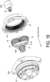
- the second carrier 60 includes a base part 61 and a bushing 62 as illustrated in FIGS. 16 and 17 .
- FIG. 16 is an exploded perspective view illustrating an example of the speed reducer according to the second embodiment.
- FIG. 17 is a perspective view illustrating an example of attachment of the second carrier to the first carrier according to the second embodiment.
- Through holes 6p and a through hole 69 are formed in the base part 61 as illustrated in FIGS. 16 and 17 .
- Through holes 6q and a through hole 6z are formed in the bushing 62.
- Second planetary shafts 78 are inserted into the through holes 6p and the through holes 6q.
- the bushing 62 is press-fitted into the base part 61 via the second planetary shafts 78.
- the adapter B89 is press-fitted into the through hole 6z, and the first sun gear B84 is press-fitted into the through hole 69.
- the second carrier 60 rotates in conjunction with the rotation of the adapter B89.
- the first sun gear B84 rotates in conjunction with the rotation of the second carrier 60.
- the base part 61 and the bushing 62 are examples of a pair of support members.
- FIG. 18 is a perspective view illustrating an example of the second carrier attached to the first carrier according to the second embodiment.
- the end part of the base part 61 at the positive direction side in the axial direction protrudes further toward the positive direction side in the axial direction than the end part 5P of the revolving part 50 at the negative direction side in the axial direction by a length P1 as illustrated in FIG. 18 .
- the base part 61 faces the bearing 51 in the radial direction.
- the length of the speed reducer including the two-staged planetary gears in the axial direction can be reduced.
- the relationship between the length P1 and the height of the base part 61 is not limited to the configuration, and for example, only a part of the base part 61 may protrude from the end part 5P, or a part of the second planetary gears 70 may also protrude from the end part 5P.
- the second planetary gears 70 are supported by the second planetary shafts 78 via a pair of bearings 72 and 73 in the radial direction, for example, as illustrated in FIG. 19 .
- the bearings 72 and 73 are further supported by wave washers 77 in addition to washers 74 and 75.
- FIG. 19 is an exploded perspective view illustrating an example of the second carrier according to the second embodiment.
- bearings 72 and 73 bearings having a diameter smaller than the diameter of the bearing 41, for example, are used.
- the bearings 72 and 73 are ball bearings, for example.
- the bearings 72 and 73 may also have flanges in the axial direction, for example.
- the three washers 74 are disposed between the base part 61 of the second carrier 60 and the bearings 72 in the axial direction as illustrated in FIG. 19 .
- the three washers 75 are disposed between the bearings 73 and the bushing 62 in the axial direction.
- the wave washers 77 are further disposed between the bushing 62 and the washers 75 in the axial direction as illustrated in FIG. 19 .
- the wave washers 77 are deformed by being pressed toward the positive direction side in the axial direction by the bushing 62. Accordingly, since the bearings 72 and 73 support the planetary gears 70 having no gap in the axial direction, the support accuracy for the planetary gears 70 is improved, the durability of the gears can be improved, and backlash can be reduced.
- the speed reducer B2 includes the first carrier 30 located at one side in the axial direction and the second carrier 60 located at the other side in the axial direction.
- a plurality of first planetary gears 40 are accommodated in the first carrier 30.
- a plurality of second planetary gears 70 are accommodated in the second carrier 60.
- the base part 61 corresponding to an end part at one side of the second carrier 60 in the axial direction protrudes further toward one side in the axial direction than the end part 5P of the first carrier 30 at the other side in the axial direction.
- the embodiments are not limited to the configuration.
- the wave washers 77 may be disposed between the base part 61 and the washers 74 at the positive direction side in the axial direction.
- the inner diameter R1 of the through hole 29 is smaller than the inner diameter R2 of the through hole 19, the embodiment is not limited to this, and the inner diameter R1 and the inner diameter R2 may be substantially the same, or the inner diameter R1 may be greater than the inner diameter R2.
- a spigot part having substantially the same shape as the spigot part 21 of the main body part 20 in the first embodiment is formed.
- the second screw 92 is fixed to a screw groove having substantially the same shape as the screw groove 2v illustrated in FIG. 3 .
- the shape of the first main body part is not limited to the above-described shape.
- a spigot part C21 may have a shape cut out in the radial direction, or may have a through hole C2q instead of the screw groove 2v as illustrated in FIGS. 20 to 22 .
- FIG. 20 is a cross-sectional view illustrating an example of a speed reducer according to a second modification.
- FIG. 21 is a cross-sectional perspective view illustrating the example of the speed reducer according to the second modification.
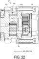
- FIG. 22 is a side cross-sectional view illustrating an example of the speed reducer according to the second modification.
- FIG. 21 illustrates a cross section cut along the plane PC illustrated in FIG. 20 .
- FIG. 22 illustrates a cross section cut along the plane PD illustrated in FIG. 20 .
- the outer diameter of a second sun gear C85 in the second modification is greater than the outer diameter of the second sun gear 85 in the second embodiment as illustrated in FIG. 21 .
- an adapter C89 is also formed to mesh with the second sun gear C85.
- the spigot part C21 formed in the first main body part C20 in the second modification further includes a cutout part C22 having a size in the radial direction smaller than the size of other parts as illustrated in FIG. 21 .
- a depth Da (a size in the radial direction) of the cutout part C22 illustrated in FIG. 22 is, for example, equal to or greater than 2 mm, and is in a range ensuring a strength of a first internal gear C24 illustrated in FIG. 21 .
- the speed reducer C2 can be reduced in weight.
- a second screw 92 is fixed to a through hole C2q formed in the first main body part C20.
- an effective screw length (a meshing length between the second screw 92 and the first main body part C20) can be sufficiently secured even when the first main body part C20 is reduced in thickness (length in the axial direction) T1 as compared with the case of having the screw groove 2v.
- the cutout part C22 is formed in the spigot part C21, even when the second screw 92 protrudes from the through hole C2q toward the positive direction side in the axial direction, the second screw 92 can be prevented from interfering with the spigot part C21.
- the speed reducer C2 can be further reduced in weight.
- the second planetary gears 70 ball bearings having a flange as described above may be used in order to ensure the size of the bearings.
- the length of the flange portion of the ball bearings needs to be checked in addition to the lengths of the planetary gears 70 in the axial direction, the length of the speed reducer in the axial direction is increased.
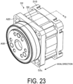
- FIG. 23 is a perspective view illustrating an example of a speed reducer according to the third modification.
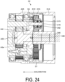
- FIG. 24 is a side cross-sectional view illustrating an example of the speed reducer according to the third modification.
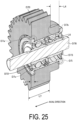
- FIG. 25 is a cross-sectional perspective view illustrating an example of a planetary gear according to the third modification.
- FIGS. 24 and 25 illustrate a cross section cut along line D-D in FIG. 23 .
- the speed reducer D2 in the third modification includes a coupling part D 10, a first main body part A20, and a second main body part D0 as illustrated in FIG. 24 .
- a second planetary gear D70 of the third modification includes a recessed portion D7a cut out from the positive direction side in the axial direction toward the negative direction side in the axial direction and a projecting portion D7b protruding toward the negative direction side in the axial direction as illustrated in FIG. 24 .
- the recessed portion D7a is cut out by a depth (size in the axial direction) L5, and the projecting portion D7b protrudes by a length (size in the axial direction) L4 as illustrated in FIG. 25 .
- the second planetary gear D70 meshes with a second internal gear D7 formed in the second main body part D0.
- a bearing D72 in the third modification includes a flange D7o protruding radially outward at the output side (positive direction side in the axial direction) as illustrated in FIG. 25 .
- a bearing D73 includes a flange D7i protruding radially outward at the input side (negative direction side in the axial direction).
- the bearings D72 and D73 may be pressed by wave washers or the like.
- a second planetary shaft D78 rotatably supporting a second planetary gear 70 via the bearings D72 and D73 is press-fitted into a base part D61 and a bushing D62 of a second carrier D60.
- the recessed portion D7a of the second planetary gear D70 holds the flange D7o of the bearing D72 in the axial direction as illustrated in FIG. 25 .
- the projecting portion D7b of the second planetary gear D70 holds the flange D7i of the bearing D73 in the axial direction.
- an interval L6 between the flanges of the two bearings D72 and D73 in the axial direction can be made greater than a length L7 of the tooth tip of the second planetary gear D70 in the axial direction. This allows a larger-sized bearing to be used.
- the speed reducer D2 according to the third modification may include a revolving part A50 having a nut 54 mounted from the negative direction side in the axial direction as in the first modification as illustrated in FIG. 24 , and the output shaft of a motor A9 may be press-fitted to the radially inner side of a second sun gear D85.
- a through hole D2q allowing the second screw 92 to be fixed may be formed in the first main body part D20 in the third modification as illustrated in FIG. 23 , as in the first and second modifications. According to this configuration, the thicknesses (sizes in the axial direction) of the speed reducer D2 can be further reduced, similarly to the first and second modifications.
- the positions of the recessed portion D7a and the projecting portion D7b formed in the second planetary gear D70 illustrated in the third modification are merely examples, and for example, the projecting portion may be formed at the positive direction side in the axial direction and the recessed portion may be formed at the negative direction side in the axial direction.
Landscapes
- Engineering & Computer Science (AREA)
- General Engineering & Computer Science (AREA)
- Mechanical Engineering (AREA)
- Power Engineering (AREA)
- Retarders (AREA)
Abstract
Description
- The present invention relates to a speed reducer.
- In a speed reducer employing a planetary gear mechanism, there is known a technique to support a carrier holding the planetary gears in a double support structure by disposing bearings to sandwich the planetary gears in the axial direction.
-
- Patent Document 1:
JP 2020-180670 A - Patent Document 2:
JP 2-9352 - Patent Document 3:
JP 5561940 B - In order to insert the carrier from the input side in the speed reducer with the double support structure, the size of the bearings at the output side may be made smaller than the inner diameter of the internal gear or the outer diameter of the plurality of planetary gears. In this case, since the two bearings have different sizes, the rigidity cannot be ensured, and pressure application to the planetary gears may be difficult to adjust.
- In one aspect, a speed reducer capable of improving rigidity is to be provided.
- In one aspect, a speed reducer includes a sun gear, an internal gear, and a planetary gear meshing with the sun gear and the internal gear. The speed reducer includes two bearings disposed to sandwich the planetary gear in an axial direction. At least one of the two bearings is pressed against the planetary gear in an axial direction by an engaging member.
- According to one aspect, rigidity can be improved.
-
-
FIG. 1 is a perspective view illustrating an example of a drive device according to a first embodiment. -
FIG. 2 is a perspective view illustrating one example of a speed reducer according to the first embodiment. -
FIG. 3 is a side cross-sectional view illustrating an example of the speed reducer according to the first embodiment. -
FIG. 4 is a cross-sectional perspective view illustrating an example of the drive device according to the first embodiment. -
FIG. 5 is another side cross-sectional view illustrating an example of the speed reducer according to the first embodiment. -
FIG. 6 is a view illustrating an example of a carrier equipped with a bearing according to the first embodiment. -
FIG. 7 is an exploded perspective view illustrating an example of the carrier according to the first embodiment. -
FIG. 8 is an exploded perspective view illustrating an example of a speed reducer assembly process according to the first embodiment. -
FIG. 9 is an exploded perspective view illustrating an example of the speed reducer assembly process according to the first embodiment. -
FIG. 10 is a perspective view illustrating an example of a revolving part according to the first embodiment. -
FIG. 11 is a perspective view illustrating an example of a speed reducer according to a first modification. -
FIG. 12 is a side cross-sectional view illustrating an example of the speed reducer according to the first modification. -
FIG. 13 is a cross-sectional perspective view illustrating an example of a revolving part according to a first modification. -
FIG. 14 is a perspective view illustrating an example of a carrier according to the first modification. -
FIG. 15 is a cross-sectional perspective view illustrating an example of a speed reducer according to a second embodiment. -
FIG. 16 is an exploded perspective view illustrating an example of the speed reducer according to the second embodiment. -
FIG. 17 is a perspective view illustrating an example of attachment of a second carrier to a first carrier according to the second embodiment. -
FIG. 18 is a perspective view illustrating an example of the second carrier attached to the first carrier according to the second embodiment. -
FIG. 19 is an exploded perspective view illustrating an example of the second carrier according to the second embodiment. -
FIG. 20 is a cross-sectional view illustrating an example of a speed reducer according to a second modification. -
FIG. 21 is a cross-sectional perspective view illustrating the example of the speed reducer according to the second modification. -
FIG. 22 is a side cross-sectional view illustrating an example of the speed reducer according to the second modification. -
FIG. 23 is a perspective view illustrating an example of a speed reducer according to a third modification. -
FIG. 24 is a side cross-sectional view illustrating an example of the speed reducer according to the third modification. -
FIG. 25 is a cross-sectional perspective view illustrating an example of a planetary gear according to the third modification. - Embodiments of a speed reducer disclosed in the present application will be described below in detail with reference to the drawings. Note that dimensional relationships between elements and scales of elements in the drawings may differ from actual configurations. The drawings may include parts having mutually different dimensional relationships and scales. In order to make the description easier to understand, each drawing may illustrate a coordinate system. In the coordinate system, an extending direction of an
output shaft 98 to be described below is defined as an axial direction and a rotation direction of theoutput shaft 98 is defined as a circumferential direction. - First, a drive device according to a first embodiment will be described with reference to
FIG. 1. FIG. 1 is a perspective view illustrating an example of a drive device according to a first embodiment. As illustrated inFIG. 1 , thedrive device 1 according to the present embodiment includes aspeed reducer 2 and amotor 9. Thespeed reducer 2 includes acoupling part 10 and amain body part 20. In the following description, the side of the location of themotor 9 may be referred to as a negative direction side in the axial direction, and the side of the location of thespeed reducer 2 may be referred to as a positive direction side in the axial direction. - The
main body part 20 of thespeed reducer 2 is coupled to themotor 9 via thecoupling part 10. More specifically, thecoupling part 10 is fixed to themotor 9 by a plurality offirst screws 91 illustrated inFIGS. 1 to 3 , and is fixed to themain body part 20 by a plurality ofsecond screws 92.FIG. 2 is a perspective view illustrating an example of the speed reducer according to the first embodiment.FIG. 3 is a side cross-sectional view illustrating an example of the speed reducer according to the first embodiment.FIG. 3 illustrates a cross section cut along the plane PA illustrated inFIG. 2 . Note that, in the following description, fourfirst screws 91 may be indicated asfirst screws 91a to 91d to distinguish them from each other, and eightsecond screws 92 may be indicated assecond screws 92a to 92h to distinguish them from each other. - As illustrated in
FIG. 3 , thefirst screws 91 are inserted into throughholes 19 formed in thecoupling part 10 and fixed toscrew grooves 99 formed in themotor 9 shown inFIG. 1 . In addition, thesecond screws 92 are inserted into throughholes 1u formed in thecoupling part 10 and are fixed to thescrew grooves 2v formed in themain body part 20. In addition, in the present embodiment, throughholes 29 are formed in themain body part 20 at a position facing the throughholes 19 of thecoupling part 10 in the axial direction as illustrated inFIG. 3 . - In the present embodiment, a size (length in the axial direction) L3 of the
first screw 91 is smaller than an interval I1 between the throughhole 19 of thecoupling part 10 and the throughhole 29 of themain body part 20 in the axial direction as illustrated inFIG. 3 , for example. In the present embodiment, for example, the length of the interval I1 is 5 mm, and the length L3 of thefirst screw 91 is 16 mm. In this case, thecoupling part 10 and themain body part 20 are fixed to each other after the fourfirst screws 91 are inserted into the throughholes 19 of thecoupling part 10, for example. In addition, the throughholes 29 are formed such that the positions of the throughholes 29 in a radial direction and the circumferential direction are substantially the same as the positions of the throughholes 19 in the radial direction and the circumferential direction. - In this configuration, the
first screws 91 can be fastened after thecoupling part 10 and themain body part 20 are fixed to each other by inserting a tool T00 into a throughhole 29 from the positive direction side in the axial direction as illustrated inFIG. 3 . According to such a configuration, the length in the axial direction can be reduced, particularly in aspeed reducer 2 with only one planetary gear stage. In this case, since the interval I1 is sufficiently smaller than the size of the tool T00, thespeed reducer 2 can be fixed to themotor 9 without using a special tool or going through a special process. Note that an inner diameter R1 of the throughhole 29 is, for example, greater than an outer diameter of the tool T00 and smaller than an inner diameter R2 of the throughhole 19. - Next, a configuration for transmitting a driving force in the present embodiment will be described.
FIG. 4 is a cross-sectional perspective view illustrating an example of the drive device according to the first embodiment.FIG. 1 illustrates a cross section cut along the line A-A inFIG. 4 . Anadapter 89 illustrated inFIG. 4 rotatably connects anoutput shaft 98 of themotor 9 to asun gear 84. Thus, a driving force of themotor 9 is transmitted to thesun gear 84 via theoutput shaft 98 and theadapter 89. - The
adapter 89 according to the present embodiment is disposed, for example, on an inner peripheral side of thecoupling part 10 as illustrated inFIG. 4 . Note that, as will be described below, the output shaft of the motor may be coupled to thesun gear 84, for example, in the form of being press-fitted into a radially inner side of thesun gear 84. In addition, the output shaft of the motor and thesun gear 84 may be integrally formed by gear-cutting an end portion of the output shaft in the axial direction. - The
sun gear 84 is engaged with aplanetary gear 40 illustrated inFIG. 5 to transmit a driving force to theplanetary gear 40.FIG. 5 is another side cross-sectional view illustrating an example of the speed reducer according to the first embodiment.FIG. 5 illustrates a cross section cut along the line A-A inFIG. 1 . In the present embodiment, theplanetary gear 40 is rotatably held by thecarrier 30 via aplanetary shaft 48 as illustrated inFIG. 5 . Theplanetary gear 40 is rotatably supported by theplanetary shaft 48 via abearing 41 as illustrated inFIG. 5 . In the present embodiment, for example, a roller bearing is used as thebearing 41. Note that thebearing 41 may be, for example, a full roller bearing with no cage. - A bearing 51 illustrated in
FIG. 6 is mounted at thecarrier 30 illustrated inFIG. 5 .FIG. 6 is a view illustrating an example of the carrier equipped with the bearing according to the first embodiment. In the present embodiment, threeplanetary gears 40 are held by thecarrier 30. Note that, the threeplanetary gears 40 may be described below as aplanetary gear 40a to aplanetary gear 40c to distinguish them from each other. - The
carrier 30 of the present embodiment includes afirst member 31 and asecond member 32 as illustrated inFIG. 6 . Thefirst member 31 and thesecond member 32 are assembled to face each other in the axial direction as illustrated inFIG. 7. FIG. 7 is an exploded perspective view illustrating an example of the carrier according to the first embodiment. Thefirst member 31 includes anouter ring 33 and acoupling surface 37 as illustrated inFIG. 7 . Thesecond member 32 includes anouter ring 34 and astrut 38. Thestrut 38 is formed at a position adjacent to theplanetary gears 40 in the circumferential direction as illustrated inFIG. 7 . - The three
planetary gears 40 in the present embodiment are held by thecarrier 30 after thebearing 51 is mounted at thecarrier 30. More specifically, thebearing 51 is mounted at theouter ring 34 of thesecond member 32 of thecarrier 30 from the positive direction side in the axial direction. Thefirst member 31 and thesecond member 32 are assembled after thebearing 51 is mounted at thesecond member 32. According to this configuration, the bearing 51 can be formed such that the outer diameter of thebearing 51 is positioned at the outer diameter side of the tooth tips of theplanetary gears 40 in the radial direction. - In addition, a through
hole 3s and ascrew groove 3v are formed in thefirst member 31, and throughholes second member 32 as illustrated inFIG. 5 . The throughhole 3u is formed to pass through thestrut 38 in the axial direction as illustrated inFIG. 7 . Theplanetary shafts 48 illustrated inFIG. 5 are inserted into the throughholes first member 31 and thesecond member 32 are positioned by theplanetary shafts 48 to be assembled. - An
internal gear 24 is formed at the inner peripheral side of themain body part 20 as illustratedFIG. 5 . Theplanetary gears 40 rotating in conjunction with thesun gear 84 mesh with theinternal gear 24 to revolve along theinternal gear 24. At this time, thecarrier 30 holding theplanetary gears 40 via theplanetary shafts 48 rotates in conjunction with the revolution of the planetary gears 40. Note that theinternal gear 24 in the present embodiment is fixed to themain body part 20 and does not rotate regardless of the revolution or rotation of the planetary gears 40. - An
external screw 35 is formed on theouter ring 33 of thefirst member 31, and aflange 36 is formed on theouter ring 34 of thesecond member 32 as illustrated inFIG. 7 . Anut 53 illustrated inFIG. 5 is mounted at theexternal screw 35. A bearing 51 mounted from the positive direction side in the axial direction is supported by theflange 36. - In the present embodiment, the
first member 31 and thesecond member 32 are fixed bythird screws 93 as illustrated inFIG. 7 . The threethird screws 93a to 93c are inserted into the throughholes 3u formed in thesecond member 32 and are respectively fixed to thescrew grooves 3v formed in thefirst member 31. Note that thethird screws 93 are an example of a locking member. - The
carrier 30 of the present embodiment is constituted by two members, namely, thefirst member 31 and thesecond member 32 as described above. In addition, thefirst member 31 and thesecond member 32 are positioned by theplanetary shafts 48. According to this configuration, workability and assemblability of thecarrier 30 are improved, and a decrease in the accuracy of theplanetary gears 40 can be curbed. - The
carrier 30 is assembled in a state of having the bearing 51 mounted as illustrated inFIG. 6 and theplanetary gears 40 being positioned, and then thecarrier 30 is inserted into themain body part 20 from the negative direction side in the axial direction as indicated by the arrow inFIG. 8. FIG. 8 is an exploded perspective view illustrating an example of a speed reducer assembly process according to the first embodiment. A portion including theexternal screw 35 of thefirst member 31 of thecarrier 30 inserted into themain body part 20 protrudes further toward the positive direction side in the axial direction than the end portion of themain body part 20 at the positive direction side in the axial direction as illustrated inFIG. 9. FIG. 9 is an exploded perspective view illustrating an example of the speed reducer assembly process according to the first embodiment. Then, abearing 52 and anut 53 are further attached to thefirst member 31 of thecarrier 30 inserted into themain body part 20 as indicated by the arrows inFIG. 9 . - In the present embodiment, the
bearing 52 is attached to theouter ring 33 of thefirst member 31 from the positive direction side in the axial direction. In the present embodiment, thebearings nut 53 is further mounted at thecarrier 30 with the bearing 52 mounted. Note that thenut 35 is an example of an engaging member. In addition, in the following description, thecarrier 30 holding theplanetary gears 40 and further having thebearings nut 53 mounted may be referred to as a revolvingpart 50. -
FIG. 10 is a perspective view illustrating an example of the revolving part according to the first embodiment. Theplanetary gears 40 are interposed between the bearing 51 and thebearing 52 in the axial direction as illustrated inFIG. 10 . Note that, although not illustrated inFIG. 10 , thebearing 52 is mounted at thecarrier 30 such that theinternal gear 24 of themain body part 20 is interposed between the bearing 52 and thebearing 51 in the axial direction. - The
nut 53 presses thebearings part 25 of themain body part 20 and theflange 36 of thesecond member 32 by thenut 53. In addition, the bearing 52 positioned at the output side (the positive direction side in the axial direction) is pressed by thenut 53 against theplanetary gears 40, the receivingpart 26 of themain body part 20, and theinternal gear 24. - According to this configuration, the inner rings of the two
bearings internal gear 24 in the axial direction and are both supported by themain body part 20 in the radial direction. As a result, the occurrence of warping or the like due to a load caused by rotation of thecarrier 30 is curbed. - In the present embodiment, in order to reduce the interval I1 illustrated in
FIG. 3 , a part of thecoupling part 10 at the positive direction side in the axial direction is positioned further at the positive direction side in the axial direction than the end portion of thebearing 51 at the negative direction side in the axial direction. That is, the receivingpart 15 formed in thecoupling part 10 faces the bearing 51 in the radial direction as illustrated inFIG. 5 . Thus, a part of thebearing 51 is further supported by the receivingpart 15 of thecoupling part 10 in the axial direction and the radial direction. According to this configuration, loads of thecarrier 30 are dispersed to thecoupling part 10 in addition to themain body part 20. - Note that, for example,
grooves 3r for fixing a driving target are formed in thecoupling surface 37 of the first member as illustrated inFIG. 4 . In the present embodiment, for example, a driving target (not illustrated) such as a robot arm is fixed to thefirst member 31 by a screw or the like, to rotate in conjunction with thecarrier 30. In addition, in the present embodiment, aspigot part 21 to be coupled to a driving object or the like is formed on the outer peripheral surface of themain body part 20 as illustrated inFIGS. 4 and5 . - As described above, the
bearings internal gear 24 in the axial direction in the present embodiment. In this configuration, the outer diameter of thebearing 52 at the output side (the positive direction side in the axial direction) can be made the same as the outer diameter of thebearing 51 at the input side (the positive direction side in the axial direction). Thus, the bearing 51 can tolerate a sufficient amount of load. In addition, since the amount of pressure applied to thebearings nut 53, tilting of the gears can be reduced, backlash can be reduced, and the durability of the gears can be improved. - In the present embodiment, the
carrier 30 includes thesecond member 32 with the bearing 51 mounted and thefirst member 31 with the bearing 52 mounted. For this reason, the assemblability and processability of thecarrier 30 supported at both sides by the two bearings can be improved. In addition, since thefirst member 31 and thesecond member 32 are reinforced by thethird screw 93, loosening of thefirst member 31 and thesecond member 32 in the axial direction is curbed. - As described above, the
speed reducer 2 according to the present embodiment includes thesun gear 84, theinternal gear 24, and theplanetary gears 40 meshing with thesun gear 84 and theinternal gear 24. Thespeed reducer 2 includes the twobearings planetary gears 40 in the axial direction. At least one of the twobearings planetary gears 40 in the axial direction by the engagingmember 53. Furthermore, the twobearings carrier 30 holding theplanetary gears 40 is supported at both sides by the twobearings speed reducer 2 can be improved. In addition, since the amount of pressure applied to thebearings nut 53, the amount of pressure can be easily adjusted. - Although the configurations of the present embodiment have been described above, the embodiment is not limited to such configurations. For example, the
strut 38 may be formed on thefirst member 31 of thecarrier 30, instead of thesecond member 32. In addition, the number ofstruts 38 is not limited to that described above and may be different from the number ofplanetary gears 40 included in thecarrier 30. - In addition, although the
nut 53 for pressing thebearings FIGS. 11 to 14 .FIG. 11 is a perspective view illustrating an example of a speed reducer according to a first modification.FIG. 12 is a side cross-sectional view illustrating an example of the speed reducer according to the first modification.FIG. 13 is a cross-sectional perspective view illustrating an example of a revolving part according to the first modification.FIG. 14 is a perspective view illustrating an example of a carrier according to the first modification.FIGS. 12 and13 illustrates a cross section cut along the plane PB illustrated inFIG. 11 . Note that, in the following modifications and embodiments, parts identical to the parts illustrated in the drawings described previously are designated by the same reference numerals, and duplicate description will be omitted. - A drive device A1 in the first modification includes a motor A9 and a speed reducer A2 as illustrated in
FIG. 11 . A carrier A30 in the first modification includes a first member A31 and a second member A32 as illustrated inFIG. 14 . In the first modification, a flange A36 is formed on an outer ring A33 of the first member A31, and an external screw A35 is formed on an outer ring A34 of the second member A32. In addition, the first member A31 further includes a coupling surface A37, and a recessed portion A3w is further formed at a central portion of the first member A31 in the radial direction. Note that, althoughFIG. 14 illustrates the carrier A30 with no bearing 52 mounted, when a speed reducer A2 is assembled, thebearing 52 is attached to the first member A31, and thus the second member A32 is fixed to the first member A31 such that theplanetary gears 40 are held between the first member A31 and the second member A32. - In the first modification, the
bearing 52 is mounted at the carrier A30 before thebearing 51 is mounted. In the first modification, thebearing 52 is mounted at the outer ring A33 of the first member A31 from the negative direction side in the axial direction. Then, the first member A31 and the second member A32 are combined to hold the threeplanetary gears 40. - The carrier A30 with the bearing 52 mounted is inserted into the main body part A20 from the positive direction side in the axial direction. Then, the
bearing 51 and thenut 54 are further mounted at the carrier A30 inserted into the main body part A20 from the negative direction side in the axial direction as illustrated inFIG. 13 . In the first modification, thebearing 52 is supported in the radial direction by a receiving part A26 formed in the main body part A20. In addition, thebearing 51 is supported in the radial direction by a receiving part A25 formed in the main body part A20 and a receiving part A15 formed in the coupling part A10. Note that, inFIG. 13 , illustration of an internal gear A24 sandwiched between the bearing 51 and thebearing 52 in the axial direction is omitted. - Furthermore, in the first modification, an output shaft A98 of a motor A9 illustrated in
FIG. 11 is press-fitted to the radially inner side of a sun gear A84 as illustrated inFIG. 12 . The sun gear A84 is inserted into a through hole A3z of the carrier A30 and is supported by the recessed portion A3w. With this configuration, a driving force of the motor A9 is transmitted to theplanetary gears 40 via the sun gear A84. Note that thefirst screws 91 inserted into the coupling part A10 are fixed to screw grooves A99 formed in the motor A9 as illustrated inFIG. 11 . - In this configuration according to the first modification, the portion of the sun gear A84 at the negative direction side in the axial direction is suppressed from protruding from the end part of a revolving part A50 at the negative direction side in the axial direction. As a result, a thickness (length in the axial direction) L2 of the speed reducer A2 illustrated in
FIG. 12 can be made smaller than a thickness L1 of thespeed reducer 2 illustrated inFIG. 5 while the length of the sun gear A84 is maintained. - In addition, in the first modification, the
nut 54 protrudes toward the coupling part A10 side in the axial direction as illustrated inFIG. 12 . In this case, when the coupling part A10 is fixed to the motor A9, thenut 54 is not visible. According to this configuration, thenut 54 can be prevented from being subjected to an unintended operation such as disassembly after the speed reducer A2 has been assembled. - Furthermore, in the first modification, even when the length of the
adapter 89 in the axial direction is increased in order to maintain the slip torque of the sun gear A84, the length of the speed reducer A2 in the axial direction can be reduced. However, in the first modification, the output shaft A98 is desirably inserted into the sun gear A84. According to this configuration, the length of the speed reducer A2 in the axial direction can be further reduced while maintaining the length of the sun gear A84 in the axial direction. - Furthermore, a through hole A2q for insertion of the
second screw 92 may be formed in the main body part A20 instead of ascrew groove 2v in the first embodiment as illustrated inFIG. 11 . Since the thicknesses (lengths in the axial direction) of the main body part A20 can be reduced due to this configuration as will be described later, the length of the speed reducer A2 in the axial direction can be further reduced. - Although the configuration of the
speed reducer 2 provided with only one stage of theplanetary gears 40 in the first embodiment is described, the embodiment is not limited to the above-described configuration. For example, two or more stages of theplanetary gears 40 may be included. Note that, in the following description, each member such as each of theplanetary gears 40 described in the first embodiment may be attached with the term "first" such as in the case of "firstplanetary gear 40". - In a second embodiment, a speed reducer further including second
planetary gears 70 in addition to the firstplanetary gears 40 as illustrated inFIG. 15 will be described.FIG. 15 is a cross-sectional perspective view illustrating an example of the speed reducer according to the second embodiment. The speed reducer B2 according to the second embodiment further includes a second main body part B0 between a coupling part B10 and a firstmain body part 20 in the axial direction as illustrated inFIG. 15 . In the second embodiment, asecond screw 92 is further inserted into, for example, a through hole (not illustrated) formed in the second main body part B0. As a result, thecoupling part B 10, the second main body part B0, and the first main body part B20 are fixed to each other. Note that, in the second embodiment, the bearing 51 may be supported by a receiving part B5 formed in the second main body part B0 as illustrated inFIG. 15 , instead of the receivingpart 15 of thecoupling part 10 in the first embodiment. - The speed reducer B2 further includes a
second carrier 60 holding the three secondplanetary gears 70 in addition to the revolvingpart 50 including afirst carrier 30 holding the first planetary gears 40. Asecond sun gear 85 is inserted into thesecond carrier 60 from the negative direction side in the axial direction as illustrated inFIG. 15 . The secondplanetary gears 70 rotate in conjunction with thesecond sun gear 85. In addition, an adapter B89 is connected to thesecond sun gear 85. The adapter B89 is mounted at an output shaft of a motor not illustrated. Thus, a driving force of the motor is transmitted to thesecond sun gear 85 via the adapter B89. - A second internal gear B7 is formed at the inner peripheral side of the second main body part B0. The second
planetary gears 70 rotate in conjunction with thesecond sun gear 85 to mesh with the second internal gear B7 and revolve around the second internal gear B7. Thesecond carrier 60 holding the secondplanetary gears 70 rotates in accordance with the revolution of the second planetary gears 70. In addition, in the second embodiment, a first sun gear B84 inserted into the revolvingpart 50 rotates in conjunction with thesecond carrier 60. In the second embodiment, thesecond carrier 60 disposed at the input side (negative direction side in the axial direction) may be a so-called float type self-aligning carrier without support of a bearing because the influence of the second carrier on the backlash is smaller than the influence of thefirst carrier 30. - In the second embodiment, the
second carrier 60 includes abase part 61 and abushing 62 as illustrated inFIGS. 16 and17 .FIG. 16 is an exploded perspective view illustrating an example of the speed reducer according to the second embodiment.FIG. 17 is a perspective view illustrating an example of attachment of the second carrier to the first carrier according to the second embodiment. Throughholes 6p and a throughhole 69 are formed in thebase part 61 as illustrated inFIGS. 16 and17 . Throughholes 6q and a throughhole 6z are formed in thebushing 62. Secondplanetary shafts 78 are inserted into the throughholes 6p and the throughholes 6q. Thebushing 62 is press-fitted into thebase part 61 via the secondplanetary shafts 78. The adapter B89 is press-fitted into the throughhole 6z, and the first sun gear B84 is press-fitted into the throughhole 69. Thus, thesecond carrier 60 rotates in conjunction with the rotation of the adapter B89. Furthermore, the first sun gear B84 rotates in conjunction with the rotation of thesecond carrier 60. Note that thebase part 61 and thebushing 62 are examples of a pair of support members. - A part of the
base part 61 protrudes further toward the positive direction side in the axial direction than the end part of the revolvingpart 50 at the negative direction side in the axial direction as illustrated inFIG. 18. FIG. 18 is a perspective view illustrating an example of the second carrier attached to the first carrier according to the second embodiment. The end part of thebase part 61 at the positive direction side in the axial direction protrudes further toward the positive direction side in the axial direction than theend part 5P of the revolvingpart 50 at the negative direction side in the axial direction by a length P1 as illustrated inFIG. 18 . In this case, for example, thebase part 61 faces the bearing 51 in the radial direction. In this configuration, the length of the speed reducer including the two-staged planetary gears in the axial direction can be reduced. Note that, although an example of the length P1 substantially equal to the thickness (size in the axial direction) of thebase part 61 has been described, the relationship between the length P1 and the height of thebase part 61 is not limited to the configuration, and for example, only a part of thebase part 61 may protrude from theend part 5P, or a part of the secondplanetary gears 70 may also protrude from theend part 5P. - The second
planetary gears 70 are supported by the secondplanetary shafts 78 via a pair ofbearings FIG. 19 . In addition, thebearings wave washers 77 in addition towashers FIG. 19 is an exploded perspective view illustrating an example of the second carrier according to the second embodiment. In the second embodiment, for thebearings bearing 41, for example, are used. Thebearings bearings - The three
washers 74 are disposed between thebase part 61 of thesecond carrier 60 and thebearings 72 in the axial direction as illustrated inFIG. 19 . The threewashers 75 are disposed between thebearings 73 and thebushing 62 in the axial direction. - In addition, the
wave washers 77 are further disposed between thebushing 62 and thewashers 75 in the axial direction as illustrated inFIG. 19 . The wave washers 77 are deformed by being pressed toward the positive direction side in the axial direction by thebushing 62. Accordingly, since thebearings planetary gears 70 having no gap in the axial direction, the support accuracy for theplanetary gears 70 is improved, the durability of the gears can be improved, and backlash can be reduced. - As described above, the speed reducer B2 according to the second embodiment includes the
first carrier 30 located at one side in the axial direction and thesecond carrier 60 located at the other side in the axial direction. A plurality of firstplanetary gears 40 are accommodated in thefirst carrier 30. A plurality of secondplanetary gears 70 are accommodated in thesecond carrier 60. Thebase part 61 corresponding to an end part at one side of thesecond carrier 60 in the axial direction protrudes further toward one side in the axial direction than theend part 5P of thefirst carrier 30 at the other side in the axial direction. With this configuration, the length of the speed reducer B2 in the axial direction can be reduced. - Although the configuration of each of the embodiments has been described above, the embodiments are not limited to the configuration. For example, the
wave washers 77 may be disposed between thebase part 61 and thewashers 74 at the positive direction side in the axial direction. In addition, although, in the embodiment, the inner diameter R1 of the throughhole 29 is smaller than the inner diameter R2 of the throughhole 19, the embodiment is not limited to this, and the inner diameter R1 and the inner diameter R2 may be substantially the same, or the inner diameter R1 may be greater than the inner diameter R2. - In addition, in the first
main body part 20 in the second embodiment, for example, a spigot part having substantially the same shape as thespigot part 21 of themain body part 20 in the first embodiment is formed. In addition, in the firstmain body part 20, thesecond screw 92 is fixed to a screw groove having substantially the same shape as thescrew groove 2v illustrated inFIG. 3 . However, the shape of the first main body part is not limited to the above-described shape. For example, in a first main body part C20, a spigot part C21 may have a shape cut out in the radial direction, or may have a through hole C2q instead of thescrew groove 2v as illustrated inFIGS. 20 to 22 . -
FIG. 20 is a cross-sectional view illustrating an example of a speed reducer according to a second modification.FIG. 21 is a cross-sectional perspective view illustrating the example of the speed reducer according to the second modification.FIG. 22 is a side cross-sectional view illustrating an example of the speed reducer according to the second modification.FIG. 21 illustrates a cross section cut along the plane PC illustrated inFIG. 20 .FIG. 22 illustrates a cross section cut along the plane PD illustrated inFIG. 20 . Note that the outer diameter of a second sun gear C85 in the second modification is greater than the outer diameter of thesecond sun gear 85 in the second embodiment as illustrated inFIG. 21 . In addition, an adapter C89 is also formed to mesh with the second sun gear C85. - The spigot part C21 formed in the first main body part C20 in the second modification further includes a cutout part C22 having a size in the radial direction smaller than the size of other parts as illustrated in
FIG. 21 . Note that, in the second modification, a depth Da (a size in the radial direction) of the cutout part C22 illustrated inFIG. 22 is, for example, equal to or greater than 2 mm, and is in a range ensuring a strength of a first internal gear C24 illustrated inFIG. 21 . According to this configuration, since the weight of the first main body part C20 can be reduced (for example, about 5% of the entire weight of the speed reducer C2), the speed reducer C2 can be reduced in weight. - In addition, in the second modification, a
second screw 92 is fixed to a through hole C2q formed in the first main body part C20. According to this configuration, an effective screw length (a meshing length between thesecond screw 92 and the first main body part C20) can be sufficiently secured even when the first main body part C20 is reduced in thickness (length in the axial direction) T1 as compared with the case of having thescrew groove 2v. In addition, since the cutout part C22 is formed in the spigot part C21, even when thesecond screw 92 protrudes from the through hole C2q toward the positive direction side in the axial direction, thesecond screw 92 can be prevented from interfering with the spigot part C21. Thus, the speed reducer C2 can be further reduced in weight. - In addition, for the second
planetary gears 70, ball bearings having a flange as described above may be used in order to ensure the size of the bearings. However, since the length of the flange portion of the ball bearings needs to be checked in addition to the lengths of theplanetary gears 70 in the axial direction, the length of the speed reducer in the axial direction is increased. - Therefore, in a third modification, a configuration of the second planetary gears provided with a projecting portion and a recessed portion will be described.
FIG. 23 is a perspective view illustrating an example of a speed reducer according to the third modification.FIG. 24 is a side cross-sectional view illustrating an example of the speed reducer according to the third modification.FIG. 25 is a cross-sectional perspective view illustrating an example of a planetary gear according to the third modification.FIGS. 24 and25 illustrate a cross section cut along line D-D inFIG. 23 . The speed reducer D2 in the third modification includes acoupling part D 10, a first main body part A20, and a second main body part D0 as illustrated inFIG. 24 . - A second planetary gear D70 of the third modification includes a recessed portion D7a cut out from the positive direction side in the axial direction toward the negative direction side in the axial direction and a projecting portion D7b protruding toward the negative direction side in the axial direction as illustrated in
FIG. 24 . The recessed portion D7a is cut out by a depth (size in the axial direction) L5, and the projecting portion D7b protrudes by a length (size in the axial direction) L4 as illustrated inFIG. 25 . The second planetary gear D70 meshes with a second internal gear D7 formed in the second main body part D0. - A bearing D72 in the third modification includes a flange D7o protruding radially outward at the output side (positive direction side in the axial direction) as illustrated in
FIG. 25 . In addition, a bearing D73 includes a flange D7i protruding radially outward at the input side (negative direction side in the axial direction). Note that, like thebearings planetary gear 70 via the bearings D72 and D73 is press-fitted into a base part D61 and a bushing D62 of a second carrier D60. - In this configuration, the recessed portion D7a of the second planetary gear D70 holds the flange D7o of the bearing D72 in the axial direction as illustrated in
FIG. 25 . In addition, the projecting portion D7b of the second planetary gear D70 holds the flange D7i of the bearing D73 in the axial direction. - According to this configuration, an interval L6 between the flanges of the two bearings D72 and D73 in the axial direction can be made greater than a length L7 of the tooth tip of the second planetary gear D70 in the axial direction. This allows a larger-sized bearing to be used.
- In addition, the speed reducer D2 according to the third modification may include a revolving part A50 having a
nut 54 mounted from the negative direction side in the axial direction as in the first modification as illustrated inFIG. 24 , and the output shaft of a motor A9 may be press-fitted to the radially inner side of a second sun gear D85. In addition, a through hole D2q allowing thesecond screw 92 to be fixed may be formed in the first main body part D20 in the third modification as illustrated inFIG. 23 , as in the first and second modifications. According to this configuration, the thicknesses (sizes in the axial direction) of the speed reducer D2 can be further reduced, similarly to the first and second modifications. - Note that, the positions of the recessed portion D7a and the projecting portion D7b formed in the second planetary gear D70 illustrated in the third modification are merely examples, and for example, the projecting portion may be formed at the positive direction side in the axial direction and the recessed portion may be formed at the negative direction side in the axial direction.
- Although the present invention has been described above based on the embodiments and the modifications, the present invention is not limited to the embodiments and the modifications, and it goes without saying that various changes can be made without departing from the gist of the present invention. Various modifications within a scope not departing from the gist are also included in the technical scope of the present invention, and this is obvious to a person having skill in the art from the description of the claims.
- 1, A1 Drive device, 2, A2, B2, C2, D2 Speed reducer, 9, A9 Motor, 10, A10, B10, D10 Coupling part, 15, A15 Receiving part, 19, 1u Through hole, 20, A20, B20, C20 Main body part (first main body part), 21, C21 Spigot part, C22 Cutout part, 24, A24, C24 Internal gear (first internal gear), 25, 26, B5 Receiving part, 29, A2q, C2q, D2q Through hole, 2v Screw groove, 30, A30 Carrier (first carrier), 31, A31 First member, 32, A32 Second member, 33, A33, 34, A34 Outer ring, 35, A35 Outer screw, 36, A36 Flange, 37, A37 Coupling surface, 38 Strut, 3t, 3x, 3u, 3z, A3z Through hole, A3w Recessed portion, 3v Screw groove, 40 Planetary gear (first planetary gear), 41 Bearing (first bearing), 48 Planetary shaft (first planetary shaft), 50, A50 Revolving part, 51, 52 Bearing, 53, 54 Nut, 60, D60 Second carrier, 61, D61 Base part, 62 Bushing, 69, 6p, 6q, 6z Through hole, 70, D70 Second planetary gear, 72, 73, D72, D73 Bearing, 74, 75 Washer, 77 Wave washer, 78, D78 Second planetary shaft, 84, A84, B84 Sun gear (first sun gear), 85, C85, D85 Second sun gear, 89, B89, C89 Adapter, 91 First screw, 92 Second screw, 93 Third screw, 98, A98 Output shaft, 99, A99 Screw groove, B0, D0 Second main body part, B7, D7 Second internal gear, T00 Tool
Claims (16)
- A speed reducer comprising:a sun gear;an internal gear;a first planetary gear meshing with the sun gear and the internal gear; andtwo bearings disposed to sandwich the first planetary gear in an axial direction,wherein at least one of the two bearings is pressed against the first planetary gear in an axial direction by an engaging member.
- The speed reducer according to claim 1,wherein a main body part on which the internal gear is formed supports at least one of the two bearings in a radial direction, andthe two bearings have a same size in a radial direction.
- The speed reducer according to claim 2,
wherein a portion having an outer diameter smaller than an outer diameter of another portion in an axial direction of the main body part is formed at a position in the main body part facing the first planetary gear in a radial direction. - The speed reducer according to claim 2, further comprising:a coupling part fixed to a drive device,wherein the coupling part supports at least one of the bearings, which is supported by the main body part, in a radial direction.
- The speed reducer according to claim 4, further comprising:a joining member bonding the drive device and the coupling part,wherein a length of the joining member in an axial direction is larger than an interval between the coupling part and the main body part in an axial direction.
- The speed reducer according to claim 5,wherein the coupling part includes a hole part enabling the joining member to be inserted,the main body part includes a hole part formed at a position facing the hole part in an axial direction, andan inner diameter of the hole part formed in the main body part is smaller than an inner diameter of the hole part formed in the coupling part.
- The speed reducer according to any one of claims 4 to 6,
wherein the engaging member is positioned at a side closer to the drive device in an axial direction, and presses the bearing positioned at a side closer to the drive device among the two bearings against the first planetary gear. - The speed reducer according to any one of claims 2 to 6, wherein the main body part supports both of the two bearings in a radial direction.
- The speed reducer according to any one of claims 1 to 6,wherein a tooth tip of the internal gear is positioned at a radially inner side of an outer ring of the two bearings in a radial direction, andan inner ring of the two bearings is positioned at a radially outer side of a tooth tip of the first planetary gear in a radial direction.
- The speed reducer according to any one of claims 1 to 6, further comprising:a first carrier including a first member formed at one side of the first planetary gear in an axial direction; and a second member formed at the other side of the first planetary gear in an axial direction and facing the first member with the first planetary gear sandwiched between the first member and the second member in an axial direction,wherein the first member and the second member are coupled by a planetary shaft supporting the first planetary gear, andthe first carrier is supported by the two bearings facing each other having the first planetary gear sandwiched between the bearings in an axial direction.
- The speed reducer according to claim 10,wherein the second member includes at least one strut, the strut being adjacent to the first planetary gear in a circumferential direction, being in contact with the first member in an axial direction, and protruding toward one side in an axial direction, andthe first member and the second member are fixed to each other by a locking member inserted into the strut.
- The speed reducer according to claim 10,wherein the first member includes at least one strut, the strut being adjacent to the first planetary gear in a circumferential direction, being in contact with the second member in an axial direction, and protruding toward the other side in an axial direction, andthe first member and the second member are fixed to each other by a locking member inserted into the strut.
- The speed reducer according to claim 10, further comprising:a first carrier positioned at one side in an axial direction; anda second carrier positioned at the other side in an axial direction,wherein the first carrier holds a plurality of the first planetary gears,the second carrier holds a plurality of second planetary gears, andan end part of the second carrier at the one side in an axial direction protrudes further toward the one side in an axial direction than an end part of the first carrier at the other side in an axial direction.
- The speed reducer according to claim 13,wherein the first carrier is supported by two bearings, the two bearings being disposed at a radially outer side of the first carrier and facing in an axial direction, andat least a portion of the second carrier in an axial direction faces at least one of the two bearings in a radial direction.
- The speed reducer according to claim 13,wherein the second carrier includesa planetary shaft inserted into a center of the second planetary gear in a radial direction and supporting the second planetary gear,a pair of bearings disposed between the second planetary gear and the planetary shaft in a radial direction, anda pair of support members supporting the second planetary gear from both sides in an axial direction,wherein a wave washer is disposed between, in an axial direction, one of the pair of bearings at one side in an axial direction and one of the pair of the support members at the second carrier at the one side in an axial direction.
- The speed reducer according to claim 13, wherein the second carrier includesa planetary shaft inserted into a center of the second planetary gear in a radial direction and supporting the second planetary gear, anda pair of bearings disposed between the second planetary gear and the planetary shaft in a radial direction,wherein the second planetary gear includes, in a radially inner side, a projecting portion protruding toward one side in an axial direction and a recessed portion cut out from another side in an axial direction toward the one side in an axial direction,the pair of bearings includes a flange protruding radially outward, andthe flange of one of the pair of bearings positioned at the one side in an axial direction faces the projecting portion in an axial direction, and the flange of the other bearing positioned at the another side in an axial direction faces the recessed portion in an axial direction.
Applications Claiming Priority (3)
| Application Number | Priority Date | Filing Date | Title |
|---|---|---|---|
| JP2021125779A JP7671202B2 (en) | 2021-07-30 | 2021-07-30 | Gearbox |
| JP2021125778A JP2023020421A (en) | 2021-07-30 | 2021-07-30 | Decelerator |
| PCT/JP2022/028892 WO2023008466A1 (en) | 2021-07-30 | 2022-07-27 | Speed reducer |
Publications (2)
| Publication Number | Publication Date |
|---|---|
| EP4379237A1 true EP4379237A1 (en) | 2024-06-05 |
| EP4379237A4 EP4379237A4 (en) | 2025-05-07 |
Family
ID=85087735
Family Applications (1)
| Application Number | Title | Priority Date | Filing Date |
|---|---|---|---|
| EP22849527.1A Pending EP4379237A4 (en) | 2021-07-30 | 2022-07-27 | SPEED REDUCER |
Country Status (3)
| Country | Link |
|---|---|
| US (1) | US12297893B2 (en) |
| EP (1) | EP4379237A4 (en) |
| WO (1) | WO2023008466A1 (en) |
Families Citing this family (2)
| Publication number | Priority date | Publication date | Assignee | Title |
|---|---|---|---|---|
| US12483093B2 (en) * | 2023-10-12 | 2025-11-25 | Deere & Company | Rotor for electric machine |
| US12519369B2 (en) | 2023-10-12 | 2026-01-06 | Deere & Company | Electric machine |
Family Cites Families (22)
| Publication number | Priority date | Publication date | Assignee | Title |
|---|---|---|---|---|
| JPS6224157U (en) | 1985-07-29 | 1987-02-14 | ||
| JPH029352U (en) | 1988-06-30 | 1990-01-22 | ||
| DE3885445T2 (en) | 1987-08-20 | 1994-02-24 | Ichiko Industries Ltd | DRIVE MECHANISM FOR ELECTRICALLY OPERATED REAR VIEW MIRROR. |
| JPH029352A (en) | 1987-12-01 | 1990-01-12 | Takahashi Kogyo Kk | Device for loosening and transporting cooked rice |
| DE19612144C2 (en) * | 1995-05-09 | 2003-11-06 | Alpha Getriebebau Gmbh | Two-stage planetary gear transmission |
| DE19956789A1 (en) | 1999-11-25 | 2001-05-31 | Zahnradfabrik Friedrichshafen | Planetary gear for mounting on electric motor, has sealing element between sun wheel shaft, and housing arranged axially outside output shaft accommodation region in reduced diameter section |
| JP3955435B2 (en) * | 2000-12-11 | 2007-08-08 | 住友重機械工業株式会社 | Reducer output flange structure |
| JP4353735B2 (en) | 2003-06-20 | 2009-10-28 | 株式会社ハーモニック・ドライブ・システムズ | Planetary gear set |
| US8523451B2 (en) | 2005-09-01 | 2013-09-03 | Ntn Corporation | Roller bearing |
| JP4808569B2 (en) | 2006-03-03 | 2011-11-02 | Ntn株式会社 | Planetary gear unit and speed increaser for wind power generator |
| JP2006234177A (en) * | 2006-06-08 | 2006-09-07 | Harmonic Drive Syst Ind Co Ltd | Planetary gear set |
| CN101485553B (en) | 2008-01-18 | 2011-09-21 | 德昌电机(深圳)有限公司 | Device for automatically turning cover |
| JP2009197882A (en) | 2008-02-21 | 2009-09-03 | Nsk Ltd | Rolling bearing for supporting planetary gear and planetary gear device |
| KR100966915B1 (en) | 2010-03-11 | 2010-06-30 | 한월숙 | A speed reducer of a detailed planetary gear |
| JP5807401B2 (en) | 2011-06-15 | 2015-11-10 | 日産自動車株式会社 | Planetary gear mechanism |
| JP5846954B2 (en) | 2012-02-20 | 2016-01-20 | 株式会社不二工機 | Planetary gear assembly for reduction gear and motor-operated valve using the same |
| JP6148509B2 (en) * | 2013-03-22 | 2017-06-14 | オリエンタルモーター株式会社 | Reducer motor |
| US9776483B2 (en) * | 2014-11-24 | 2017-10-03 | Magna Closures Inc. | Electromechanical strut with motor-gearbox assembly having dual stage planetary gearbox |
| JP2018066451A (en) * | 2016-10-21 | 2018-04-26 | 株式会社ジェイテクト | Planetary gear device and method of manufacturing planetary gear device |
| JP6949581B2 (en) | 2017-06-27 | 2021-10-13 | ナブテスコ株式会社 | Decelerator |
| JP2019039545A (en) * | 2017-08-29 | 2019-03-14 | ミネベアミツミ株式会社 | Reduction gear and driving device |
| JP2020180670A (en) | 2019-04-26 | 2020-11-05 | ミネベアミツミ株式会社 | Speed reducer and driving device |
-
2022
- 2022-07-27 WO PCT/JP2022/028892 patent/WO2023008466A1/en not_active Ceased
- 2022-07-27 US US18/292,624 patent/US12297893B2/en active Active
- 2022-07-27 EP EP22849527.1A patent/EP4379237A4/en active Pending
Also Published As
| Publication number | Publication date |
|---|---|
| WO2023008466A1 (en) | 2023-02-02 |
| EP4379237A4 (en) | 2025-05-07 |
| US12297893B2 (en) | 2025-05-13 |
| US20240288050A1 (en) | 2024-08-29 |
Similar Documents
| Publication | Publication Date | Title |
|---|---|---|
| JP4847892B2 (en) | Oscillating intermeshing planetary gear device and manufacturing method of eccentric shaft thereof | |
| TWI550211B (en) | An internal gear unit with a composite rolling bearing and a harmonic gear device | |
| EP2381130A2 (en) | Speed change gear | |
| US11835113B2 (en) | Gear pair and nutation reducer | |
| EP2639477B1 (en) | Planetary gear reducer | |
| EP2749789A1 (en) | Gear device | |
| US12297893B2 (en) | Speed reducer | |
| CN105121901B (en) | Decelerator | |
| US11788606B2 (en) | Transmission mechanism | |
| US11353090B2 (en) | Speed reducer | |
| EP2730804B1 (en) | Epicyclic reduction gear | |
| JPH09317833A (en) | Planetary gear | |
| JPH05296300A (en) | Series of speed increaser and reducer employing internal meshing type epicyclic gear structure | |
| WO2020015589A1 (en) | Planetary gear mechanism without backlash and planetary reducer | |
| JP2888674B2 (en) | Inner mesh planetary gear structure | |
| JP7671202B2 (en) | Gearbox | |
| JP2003074646A (en) | Internal gear structure for internal meshing planetary gears | |
| JP2023020421A (en) | Decelerator | |
| TWI694217B (en) | A power transmission apparatus with an inscribed cam and cylinderical pinions | |
| CN115523264A (en) | Cycloidal pin gear speed reducer | |
| CN217422054U (en) | Reduction gear and robot | |
| CN217713522U (en) | Cydariform tooth planet cycloid speed reducer and power device | |
| CN112081897A (en) | Support portion structure of transmission gear, speed reducer, and rotary device | |
| CN224214641U (en) | RV speed reduction structure with high input precision | |
| CN111981106B (en) | Input shaft and reducer |
Legal Events
| Date | Code | Title | Description |
|---|---|---|---|
| STAA | Information on the status of an ep patent application or granted ep patent |
Free format text: STATUS: THE INTERNATIONAL PUBLICATION HAS BEEN MADE |
|
| PUAI | Public reference made under article 153(3) epc to a published international application that has entered the european phase |
Free format text: ORIGINAL CODE: 0009012 |
|
| STAA | Information on the status of an ep patent application or granted ep patent |
Free format text: STATUS: REQUEST FOR EXAMINATION WAS MADE |
|
| 17P | Request for examination filed |
Effective date: 20240228 |
|
| AK | Designated contracting states |
Kind code of ref document: A1 Designated state(s): AL AT BE BG CH CY CZ DE DK EE ES FI FR GB GR HR HU IE IS IT LI LT LU LV MC MK MT NL NO PL PT RO RS SE SI SK SM TR |
|
| DAV | Request for validation of the european patent (deleted) | ||
| DAX | Request for extension of the european patent (deleted) | ||
| P01 | Opt-out of the competence of the unified patent court (upc) registered |
Free format text: CASE NUMBER: APP_52599/2024 Effective date: 20240919 |
|
| A4 | Supplementary search report drawn up and despatched |
Effective date: 20250409 |
|
| RIC1 | Information provided on ipc code assigned before grant |
Ipc: F16H 57/023 20120101ALI20250403BHEP Ipc: H02K 7/116 20060101ALI20250403BHEP Ipc: F16H 1/46 20060101ALI20250403BHEP Ipc: F16H 1/28 20060101AFI20250403BHEP |