EP4379180A1 - Hood assembly for a work vehicle - Google Patents
Hood assembly for a work vehicle Download PDFInfo
- Publication number
- EP4379180A1 EP4379180A1 EP23213543.4A EP23213543A EP4379180A1 EP 4379180 A1 EP4379180 A1 EP 4379180A1 EP 23213543 A EP23213543 A EP 23213543A EP 4379180 A1 EP4379180 A1 EP 4379180A1
- Authority
- EP
- European Patent Office
- Prior art keywords
- hood
- linear actuator
- assembly
- pivot joint
- pivotally coupled
- Prior art date
- Legal status (The legal status is an assumption and is not a legal conclusion. Google has not performed a legal analysis and makes no representation as to the accuracy of the status listed.)
- Pending
Links
- 230000007246 mechanism Effects 0.000 claims abstract description 37
- 239000000853 adhesive Substances 0.000 description 5
- 230000001070 adhesive effect Effects 0.000 description 5
- 239000000463 material Substances 0.000 description 4
- 230000008901 benefit Effects 0.000 description 2
- 238000001816 cooling Methods 0.000 description 2
- 230000008878 coupling Effects 0.000 description 2
- 238000010168 coupling process Methods 0.000 description 2
- 238000005859 coupling reaction Methods 0.000 description 2
- 238000013461 design Methods 0.000 description 2
- 238000004519 manufacturing process Methods 0.000 description 2
- 238000000034 method Methods 0.000 description 2
- 230000008569 process Effects 0.000 description 2
- 229920000049 Carbon (fiber) Polymers 0.000 description 1
- 229920002430 Fibre-reinforced plastic Polymers 0.000 description 1
- 241001124569 Lycaenidae Species 0.000 description 1
- 229910000831 Steel Inorganic materials 0.000 description 1
- 229910052782 aluminium Inorganic materials 0.000 description 1
- XAGFODPZIPBFFR-UHFFFAOYSA-N aluminium Chemical compound [Al] XAGFODPZIPBFFR-UHFFFAOYSA-N 0.000 description 1
- 230000005540 biological transmission Effects 0.000 description 1
- 239000004917 carbon fiber Substances 0.000 description 1
- 239000002131 composite material Substances 0.000 description 1
- 230000008602 contraction Effects 0.000 description 1
- 239000011151 fibre-reinforced plastic Substances 0.000 description 1
- 239000011152 fibreglass Substances 0.000 description 1
- 229910052751 metal Inorganic materials 0.000 description 1
- 239000002184 metal Substances 0.000 description 1
- VNWKTOKETHGBQD-UHFFFAOYSA-N methane Chemical compound C VNWKTOKETHGBQD-UHFFFAOYSA-N 0.000 description 1
- 238000012986 modification Methods 0.000 description 1
- 230000004048 modification Effects 0.000 description 1
- 239000012858 resilient material Substances 0.000 description 1
- 239000007787 solid Substances 0.000 description 1
- 239000010959 steel Substances 0.000 description 1
Images




Classifications
-
- B—PERFORMING OPERATIONS; TRANSPORTING
- B62—LAND VEHICLES FOR TRAVELLING OTHERWISE THAN ON RAILS
- B62D—MOTOR VEHICLES; TRAILERS
- B62D25/00—Superstructure or monocoque structure sub-units; Parts or details thereof not otherwise provided for
- B62D25/08—Front or rear portions
- B62D25/10—Bonnets or lids, e.g. for trucks, tractors, busses, work vehicles
- B62D25/12—Parts or details thereof
-
- B—PERFORMING OPERATIONS; TRANSPORTING
- B62—LAND VEHICLES FOR TRAVELLING OTHERWISE THAN ON RAILS
- B62D—MOTOR VEHICLES; TRAILERS
- B62D25/00—Superstructure or monocoque structure sub-units; Parts or details thereof not otherwise provided for
- B62D25/08—Front or rear portions
- B62D25/10—Bonnets or lids, e.g. for trucks, tractors, busses, work vehicles
-
- E—FIXED CONSTRUCTIONS
- E05—LOCKS; KEYS; WINDOW OR DOOR FITTINGS; SAFES
- E05C—BOLTS OR FASTENING DEVICES FOR WINGS, SPECIALLY FOR DOORS OR WINDOWS
- E05C17/00—Devices for holding wings open; Devices for limiting opening of wings or for holding wings open by a movable member extending between frame and wing; Braking devices, stops or buffers, combined therewith
- E05C17/02—Devices for holding wings open; Devices for limiting opening of wings or for holding wings open by a movable member extending between frame and wing; Braking devices, stops or buffers, combined therewith by mechanical means
- E05C17/04—Devices for holding wings open; Devices for limiting opening of wings or for holding wings open by a movable member extending between frame and wing; Braking devices, stops or buffers, combined therewith by mechanical means with a movable bar or equivalent member extending between frame and wing
- E05C17/30—Devices for holding wings open; Devices for limiting opening of wings or for holding wings open by a movable member extending between frame and wing; Braking devices, stops or buffers, combined therewith by mechanical means with a movable bar or equivalent member extending between frame and wing of extensible, e.g. telescopic, construction
-
- E—FIXED CONSTRUCTIONS
- E05—LOCKS; KEYS; WINDOW OR DOOR FITTINGS; SAFES
- E05C—BOLTS OR FASTENING DEVICES FOR WINGS, SPECIALLY FOR DOORS OR WINDOWS
- E05C17/00—Devices for holding wings open; Devices for limiting opening of wings or for holding wings open by a movable member extending between frame and wing; Braking devices, stops or buffers, combined therewith
- E05C17/02—Devices for holding wings open; Devices for limiting opening of wings or for holding wings open by a movable member extending between frame and wing; Braking devices, stops or buffers, combined therewith by mechanical means
- E05C17/04—Devices for holding wings open; Devices for limiting opening of wings or for holding wings open by a movable member extending between frame and wing; Braking devices, stops or buffers, combined therewith by mechanical means with a movable bar or equivalent member extending between frame and wing
- E05C17/32—Devices for holding wings open; Devices for limiting opening of wings or for holding wings open by a movable member extending between frame and wing; Braking devices, stops or buffers, combined therewith by mechanical means with a movable bar or equivalent member extending between frame and wing consisting of two or more pivoted rods
-
- E—FIXED CONSTRUCTIONS
- E05—LOCKS; KEYS; WINDOW OR DOOR FITTINGS; SAFES
- E05F—DEVICES FOR MOVING WINGS INTO OPEN OR CLOSED POSITION; CHECKS FOR WINGS; WING FITTINGS NOT OTHERWISE PROVIDED FOR, CONCERNED WITH THE FUNCTIONING OF THE WING
- E05F15/00—Power-operated mechanisms for wings
- E05F15/60—Power-operated mechanisms for wings using electrical actuators
- E05F15/603—Power-operated mechanisms for wings using electrical actuators using rotary electromotors
- E05F15/611—Power-operated mechanisms for wings using electrical actuators using rotary electromotors for swinging wings
- E05F15/616—Power-operated mechanisms for wings using electrical actuators using rotary electromotors for swinging wings operated by push-pull mechanisms
-
- E—FIXED CONSTRUCTIONS
- E05—LOCKS; KEYS; WINDOW OR DOOR FITTINGS; SAFES
- E05F—DEVICES FOR MOVING WINGS INTO OPEN OR CLOSED POSITION; CHECKS FOR WINGS; WING FITTINGS NOT OTHERWISE PROVIDED FOR, CONCERNED WITH THE FUNCTIONING OF THE WING
- E05F15/00—Power-operated mechanisms for wings
- E05F15/60—Power-operated mechanisms for wings using electrical actuators
- E05F15/603—Power-operated mechanisms for wings using electrical actuators using rotary electromotors
- E05F15/611—Power-operated mechanisms for wings using electrical actuators using rotary electromotors for swinging wings
- E05F15/63—Power-operated mechanisms for wings using electrical actuators using rotary electromotors for swinging wings operated by swinging arms
-
- E—FIXED CONSTRUCTIONS
- E05—LOCKS; KEYS; WINDOW OR DOOR FITTINGS; SAFES
- E05F—DEVICES FOR MOVING WINGS INTO OPEN OR CLOSED POSITION; CHECKS FOR WINGS; WING FITTINGS NOT OTHERWISE PROVIDED FOR, CONCERNED WITH THE FUNCTIONING OF THE WING
- E05F15/00—Power-operated mechanisms for wings
- E05F15/70—Power-operated mechanisms for wings with automatic actuation
-
- E—FIXED CONSTRUCTIONS
- E05—LOCKS; KEYS; WINDOW OR DOOR FITTINGS; SAFES
- E05F—DEVICES FOR MOVING WINGS INTO OPEN OR CLOSED POSITION; CHECKS FOR WINGS; WING FITTINGS NOT OTHERWISE PROVIDED FOR, CONCERNED WITH THE FUNCTIONING OF THE WING
- E05F15/00—Power-operated mechanisms for wings
- E05F15/50—Power-operated mechanisms for wings using fluid-pressure actuators
- E05F15/53—Power-operated mechanisms for wings using fluid-pressure actuators for swinging wings
-
- E—FIXED CONSTRUCTIONS
- E05—LOCKS; KEYS; WINDOW OR DOOR FITTINGS; SAFES
- E05Y—INDEXING SCHEME ASSOCIATED WITH SUBCLASSES E05D AND E05F, RELATING TO CONSTRUCTION ELEMENTS, ELECTRIC CONTROL, POWER SUPPLY, POWER SIGNAL OR TRANSMISSION, USER INTERFACES, MOUNTING OR COUPLING, DETAILS, ACCESSORIES, AUXILIARY OPERATIONS NOT OTHERWISE PROVIDED FOR, APPLICATION THEREOF
- E05Y2201/00—Constructional elements; Accessories therefor
- E05Y2201/20—Brakes; Disengaging means; Holders; Stops; Valves; Accessories therefor
- E05Y2201/218—Holders
- E05Y2201/22—Locks
-
- E—FIXED CONSTRUCTIONS
- E05—LOCKS; KEYS; WINDOW OR DOOR FITTINGS; SAFES
- E05Y—INDEXING SCHEME ASSOCIATED WITH SUBCLASSES E05D AND E05F, RELATING TO CONSTRUCTION ELEMENTS, ELECTRIC CONTROL, POWER SUPPLY, POWER SIGNAL OR TRANSMISSION, USER INTERFACES, MOUNTING OR COUPLING, DETAILS, ACCESSORIES, AUXILIARY OPERATIONS NOT OTHERWISE PROVIDED FOR, APPLICATION THEREOF
- E05Y2201/00—Constructional elements; Accessories therefor
- E05Y2201/40—Motors; Magnets; Springs; Weights; Accessories therefor
- E05Y2201/47—Springs
- E05Y2201/478—Gas springs
-
- E—FIXED CONSTRUCTIONS
- E05—LOCKS; KEYS; WINDOW OR DOOR FITTINGS; SAFES
- E05Y—INDEXING SCHEME ASSOCIATED WITH SUBCLASSES E05D AND E05F, RELATING TO CONSTRUCTION ELEMENTS, ELECTRIC CONTROL, POWER SUPPLY, POWER SIGNAL OR TRANSMISSION, USER INTERFACES, MOUNTING OR COUPLING, DETAILS, ACCESSORIES, AUXILIARY OPERATIONS NOT OTHERWISE PROVIDED FOR, APPLICATION THEREOF
- E05Y2201/00—Constructional elements; Accessories therefor
- E05Y2201/60—Suspension or transmission members; Accessories therefor
- E05Y2201/622—Suspension or transmission members elements
- E05Y2201/624—Arms
-
- E—FIXED CONSTRUCTIONS
- E05—LOCKS; KEYS; WINDOW OR DOOR FITTINGS; SAFES
- E05Y—INDEXING SCHEME ASSOCIATED WITH SUBCLASSES E05D AND E05F, RELATING TO CONSTRUCTION ELEMENTS, ELECTRIC CONTROL, POWER SUPPLY, POWER SIGNAL OR TRANSMISSION, USER INTERFACES, MOUNTING OR COUPLING, DETAILS, ACCESSORIES, AUXILIARY OPERATIONS NOT OTHERWISE PROVIDED FOR, APPLICATION THEREOF
- E05Y2400/00—Electronic control; Electrical power; Power supply; Power or signal transmission; User interfaces
- E05Y2400/10—Electronic control
- E05Y2400/30—Electronic control of motors
- E05Y2400/3013—Electronic control of motors during manual wing operation
-
- E—FIXED CONSTRUCTIONS
- E05—LOCKS; KEYS; WINDOW OR DOOR FITTINGS; SAFES
- E05Y—INDEXING SCHEME ASSOCIATED WITH SUBCLASSES E05D AND E05F, RELATING TO CONSTRUCTION ELEMENTS, ELECTRIC CONTROL, POWER SUPPLY, POWER SIGNAL OR TRANSMISSION, USER INTERFACES, MOUNTING OR COUPLING, DETAILS, ACCESSORIES, AUXILIARY OPERATIONS NOT OTHERWISE PROVIDED FOR, APPLICATION THEREOF
- E05Y2900/00—Application of doors, windows, wings or fittings thereof
- E05Y2900/50—Application of doors, windows, wings or fittings thereof for vehicles
- E05Y2900/518—Application of doors, windows, wings or fittings thereof for vehicles for working vehicles
-
- E—FIXED CONSTRUCTIONS
- E05—LOCKS; KEYS; WINDOW OR DOOR FITTINGS; SAFES
- E05Y—INDEXING SCHEME ASSOCIATED WITH SUBCLASSES E05D AND E05F, RELATING TO CONSTRUCTION ELEMENTS, ELECTRIC CONTROL, POWER SUPPLY, POWER SIGNAL OR TRANSMISSION, USER INTERFACES, MOUNTING OR COUPLING, DETAILS, ACCESSORIES, AUXILIARY OPERATIONS NOT OTHERWISE PROVIDED FOR, APPLICATION THEREOF
- E05Y2900/00—Application of doors, windows, wings or fittings thereof
- E05Y2900/50—Application of doors, windows, wings or fittings thereof for vehicles
- E05Y2900/53—Type of wing
- E05Y2900/536—Hoods
Definitions
- the present disclosure relates generally to a hood assembly for a work vehicle.
- Certain work vehicles such as tractors, harvesters, and sprayers, have a hood assembly including a hood configured to facilitate access to certain components of the work vehicle, such as the engine, the cooling system, components of the hydraulic system, etc.
- the hood assembly may include one or more gas struts to offset a portion of the weight of the hood, thereby reducing operator effort in moving the hood from a closed position to an open position.
- the strut(s) may extend from a chassis of the work vehicle to the hood, and the strut(s) may urge the hood toward the open position.
- the force applied by the strut(s) may be reduced.
- the force sufficient to drive the hood from the closed position to the open position may be increased, thereby increasing operator effort in opening the hood.
- the force applied by the strut(s) may be increased.
- the force sufficient to drive the hood from the open position to the closed position may be increased, thereby increasing operator effort in closing the hood.
- a hood assembly for a work vehicle includes a hood and a hood pivot joint configured to pivotally couple the hood to a chassis of the work vehicle.
- the hood pivot joint is configured to enable the hood to rotate between an open position and a closed position.
- the hood assembly also includes a lift mechanism having a linkage assembly pivotally coupled to the hood and configured to pivotally couple to the chassis of the work vehicle.
- the lift mechanism includes a linear actuator coupled to the linkage assembly. The linear actuator is configured to drive the linkage assembly to rotate the hood between the open and closed positions.
- FIG. 1 is a perspective view of an embodiment of a work vehicle 10 having an embodiment of a hood assembly 12.
- the work vehicle 10 includes a cab 14 configured to house an operator.
- a steering wheel 16 is disposed within the cab 14 to facilitate control of the work vehicle 10.
- the cab 14 may also house additional controls to enable the operator to control various functions of the work vehicle (e.g., movement of a tool coupled to the work vehicle, speed of the work vehicle, etc.).
- the work vehicle 10 includes a chassis 18 configured to support an engine, a transmission, the hood assembly 12, other systems of the work vehicle 10, or a combination thereof.
- the work vehicle 10 includes wheels 20 configured to be driven by the engine, thereby driving the work vehicle 10 through a field.
- the work vehicle 10 includes wheels 20 in the illustrated embodiment, in other embodiments, the work vehicle may include tracks or a combination of wheels and tracks. Furthermore, while the work vehicle 10 is a tractor in the illustrated embodiment, in other embodiments, the work vehicle may be a harvester, a sprayer, a bulldozer, or any other suitable type of work vehicle.
- the hood assembly 12 includes a hood 22 and a hood pivot joint configured to pivotally couple the hood 22 to the chassis 18 of the work vehicle 10.
- the hood pivot joint is configured to enable the hood 22 to pivot between an open position and a closed position. Rotating the hood 22 to the open position facilitates access to certain component(s) of the work vehicle 10, such as the engine, a cooling system, component(s) of a hydraulic system, other suitable component(s), or a combination thereof.
- the hood 22 while the hood 22 is in the closed position, access to the component(s) is blocked, and the hood 22 may substantially reduce dirt and/or debris from collecting on the component(s).
- the hood assembly 12 includes a lift mechanism having a linkage assembly and a linear actuator.
- the linkage assembly is pivotally coupled to the hood 22 and to the chassis 18 of the work vehicle 10.
- the linear actuator is coupled (e.g., pivotally coupled) to the linkage assembly, and the linear actuator is configured to drive the linkage assembly to rotate the hood between the open and closed positions. Because the linear actuator is configured to drive the hood to rotate between the open and closed positions, operator effort associated with manually moving the hood between the open and closed positions may be substantially reduced or eliminated, thereby facilitating the hood opening and closing processes.
- FIG. 2 is a perspective view of the hood assembly 12 of FIG. 1 , in which the hood 22 of the hood assembly 12 is in the open position.
- the hood assembly 12 includes the hood 22 and a hood pivot joint 24.
- the hood pivot joint 24 is configured to pivotally couple the hood 22 to the chassis of the work vehicle, thereby enabling the hood 22 to rotate between the illustrated open position and the closed position.
- the hood assembly 12 also includes a lift mechanism 26 having a linkage assembly 28 and a linear actuator 30.
- the linkage assembly 28 is pivotally coupled to the hood 22 and to the chassis of the work vehicle.
- the linear actuator 30 is coupled (e.g., pivotally coupled) to the linkage assembly 28, and the linear actuator 30 is configured to drive the linkage assembly 28 to rotate the hood 22 between the open and closed positions. Because the linear actuator is configured to drive the hood to rotate between the open and closed positions, operator effort associated with manually moving the hood between the open and closed positions may be substantially reduced or eliminated, thereby facilitating the hood opening and closing processes. In addition, because the lift mechanism 26 drives the hood 22 to rotate between the open and closed positions, the opening angle of the hood 22 may not be limited by the reach of an operator, thereby facilitating a larger opening angle, which may enhance access to the component(s) under the hood 22.
- the linkage assembly 28 has a lower link 32 and an upper link 34.
- the lower link 32 is pivotally coupled to the chassis of the work vehicle, and the upper link 34 is pivotally coupled to the hood 22.
- the lower link 32 and the upper link 34 are pivotally coupled to one another.
- the linear actuator 30 is pivotally coupled to the lower link 32 and to the upper link 34. Accordingly, extension of the linear actuator 30 drives the lower and upper links to rotate away from one another, thereby driving the hood 22 to rotate toward the illustrated open position. In addition, retraction of the linear actuator 30 drives the lower and upper links to pivot toward one another, thereby driving the hood 22 to rotate toward the closed position.
- a relatively small extension or retraction of the linear actuator 30 drives the hood 22 to rotate through a relatively large angle, thereby enabling a large opening angle of the hood 22 with a relatively short/compact linear actuator 30.
- the linear actuator 30 is pivotally coupled to the lower link 32 and to the upper link 34 in the illustrated embodiment, in other embodiments, the linear actuator may be coupled to other suitable structure(s) to drive the hood to rotate between the open and closed positions.
- the linear actuator may be pivotally coupled to the chassis of the work vehicle (e.g., directly or via a mount/mounting structure).
- the linear actuator may be pivotally coupled to the hood of the hood assembly (e.g., directly or via a mount/mounting structure).
- the linear actuator may be pivotally coupled to the chassis and to the hood, the linear actuator may be pivotally coupled to the lower link and to the hood, or the linear actuator may be pivotally coupled to the chassis and to the upper link.
- the lift mechanism 26 includes a single linear actuator 30 in the illustrated embodiment, in other embodiments, the lift mechanism may include multiple linear actuators (e.g., 2, 3, 4, or more), and each linear actuator may be pivotally coupled to any of the structures disclosed above and/or to any other suitable structure(s).
- the linear actuator may be omitted.
- the linear actuator 30 is an electric linear actuator having a body 36 and an actuating rod 38.
- the body 36 is configured to house a driver, such as an electric motor, and the driver is configured to drive the actuating rod 38 to move relative to the body 36, thereby driving the linear actuator 30 to extend and retract.
- the body 36 of the linear actuator 30 is pivotally coupled to the lower link 32, and the actuating rod 38 is pivotally coupled to the upper link 34.
- the body of the linear actuator may be pivotally coupled to the upper link or to another suitable structure, and the actuating rod may be pivotally coupled to the lower link or to another suitable structure.
- the linear actuator is an electric linear actuator in the illustrated embodiment, in other embodiments, the linear actuator may be a pneumatic linear actuator (e.g., pneumatic cylinder, air bag, etc.), a hydraulic linear actuator (e.g., hydraulic cylinder, etc.), or another suitable type of linear actuator.
- the lift mechanism includes a linear actuator in the illustrated embodiment, in other embodiments, the lift mechanism may include a rotary actuator (e.g., electric motor, pneumatic motor, hydraulic motor, etc.) coupled to the upper and lower links and configured to drive the upper and lower links to rotate relative to one another.
- each link of the linkage assembly 28 is substantially rigid.
- Each link may be formed from any suitable material to establish the substantially rigid link, such as steel, aluminum, polymeric material, composite material (e.g., fiberglass, carbon fiber, fiber reinforced plastic, etc.), other suitable material(s), or a combination thereof.
- the linkage assembly 28 includes two links (e.g., only two links) in the illustrated embodiment, in other embodiments, the linkage assembly may include one or more additional links.
- the linkage assembly may include 3, 4, 5, 6, or more links, and the links may be pivotally coupled to one another.
- the lower link 32 is configured to rotate about an axis substantially parallel to a lateral axis 40 of the hood assembly 12 relative to the chassis of the work vehicle.
- the upper link 34 is configured to rotate about an axis substantially parallel to the lateral axis 40 relative to the hood 22.
- the lower link 32 and the upper link 34 are configured to rotate about an axis substantially parallel to the lateral axis 40 relative to one another.
- the links may be configured to rotate about other suitable axes.
- the links may be configured to rotate about respective axes substantially parallel to a longitudinal axis of the hood assembly, or the links may be configured to rotate about respective axes substantially parallel to an axis angled relative to the lateral axis and/or the longitudinal axis of the hood assembly.
- each strut 42 is a gas strut (e.g., pneumatic strut).
- at least one strut may be a hydraulic strut, a mechanical strut (e.g., including a spring), or another suitable type of strut.
- the struts 42 are positioned on opposite lateral sides of the lower and upper links (e.g., opposite sides along the lateral axis 40). However, in other embodiments, the struts may be positioned on the same lateral side of the lower and upper links, or at least one strut may be positioned between the lower and upper links along the lateral axis. Furthermore, while the lift mechanism 26 includes two struts 42 in the illustrated embodiment, in other embodiments, the lift mechanism may include more or fewer struts (e.g., 0, 1, 3, 4, 5, 6, or more), and the struts may be positioned in any suitable location(s). For example, in certain embodiments, the struts may be omitted.
- the lift mechanism may include other suitable biasing element(s) (e.g., alone or in combination with the strut(s)) configured to urge the hood toward the open position, such as coil spring(s) positioned at the hood pivot joint.
- suitable biasing element(s) e.g., alone or in combination with the strut(s)
- coil spring(s) positioned at the hood pivot joint.
- each strut 42 is pivotally coupled to the lower link 32 and to the upper link 34. Accordingly, the struts 42 urge the lower and upper links to rotate away from one another, thereby urging the hood 22 to rotate toward the illustrated open position. Furthermore, in the illustrated embodiment, each strut 42 includes a body 44 and an actuating rod 46 extending from the body 44. The actuating rod 46 is urged way from the body 44 (e.g., due to air pressure, hydraulic pressure, etc.), thereby urging the strut 42 to extend. In the illustrated embodiment, the body 44 of each strut 42 is pivotally coupled to the upper link 34, and the actuating rod 46 of each strut 42 is pivotally coupled to the lower link 32.
- the body of at least one strut may be pivotally coupled to the lower link, and the corresponding actuating rod(s) may be pivotally coupled to the upper link.
- at least one strut may not include a body and/or an actuating rod, such as a mechanical strut (e.g., including a spring).
- each strut 42 is pivotally coupled to the lower link 32 and to the upper link 34 in the illustrated embodiment, in other embodiments, at least one strut may be coupled to other suitable structure(s) to urge the hood to rotate toward the open position.
- at least one strut may be pivotally coupled to the chassis of the work vehicle (e.g., directly or via a mount/mounting structure).
- at least one strut may be pivotally coupled to the hood of the hood assembly (e.g., directly or via a mount/mounting structure).
- At least one strut may be pivotally coupled to the chassis and to the hood, at least one strut may be pivotally coupled to the lower link and to the hood, at least one strut may be pivotally coupled to the chassis and to the upper link, or a combination thereof.
- the hood pivot joint 24 is positioned at a rear portion 48 of the hood 22 relative to a longitudinal axis 50 of the hood assembly 12.
- the linkage assembly 28 e.g., the upper link 34 of the linkage assembly 28
- the lift mechanism 26 is configured to drive the front portion 52 of the hood 22 upwardly relative to a vertical axis 54 of the hood assembly 12 to rotate the hood 22 to the open position
- the lift mechanism 26 is configured to drive the front portion 52 of the hood 22 downwardly relative to the vertical axis 54 to rotate the hood 22 to the closed position.
- the longitudinal stability of the hood 22 may be enhanced (e.g., as compared to a hood assembly in which the pivot joint is positioned at the rear portion of the hood and the linkage assembly is pivotally coupled to the rear portion of the hood). While the hood pivot joint 24 is positioned at the rear portion 48 of the hood 22 and the linkage assembly 28 is pivotally coupled to the front portion 52 of the hood 22 in the illustrated embodiment, in other embodiments, the hood pivot joint may be positioned at another suitable portion of the hood and the linkage assembly may be pivotally coupled to another suitable portion of the hood.
- the hood pivot joint may be positioned at the front portion of the hood, and the linkage assembly may be pivotally coupled to the rear portion of the hood.
- the hood pivot joint may be positioned at the rear portion of the hood, and the linkage assembly may be pivotally coupled to the rear portion of the hood.
- the hood pivot joint may be positioned at the front portion of the hood, and the linkage assembly may be pivotally coupled to the front portion of the hood.
- the front portion is positioned forward of a longitudinal center of the hood (e.g., center of the hood along the longitudinal axis while the hood is in the closed position), and the rear portion is positioned rearward of the longitudinal center of the hood (e.g., center of the hood along the longitudinal axis while the hood is in the closed position).
- a longitudinal center of the hood e.g., center of the hood along the longitudinal axis while the hood is in the closed position
- the rear portion is positioned rearward of the longitudinal center of the hood (e.g., center of the hood along the longitudinal axis while the hood is in the closed position).
- the lift mechanism 26 includes a switch 53 communicatively coupled to the linear actuator 30 (e.g., electric linear actuator).
- the switch 53 is configured to control the linear actuator 30 to move the hood 22 from the illustrated open position to the closed position and to move the hood 22 from the closed position to the illustrated open position based on operator input.
- the switch 53 may be located at or near the hood 22 on an exterior of the work vehicle, or the switch 53 may be located within the cab of the work vehicle.
- the switch 53 may be integrated with a latch release mechanism 55, which is configured to release latch(es) that secure the hood 22 in the closed position.
- a handle of the latch release mechanism 55 may be located within the cab of the work vehicle, and the operator may activate the latch release mechanism 55 using the handle to disengage the latch(es) and control the linear actuator 30 to move the hood from the closed position to the open position.
- the operator may use the handle to activate the latch release mechanism 55 to control the linear actuator 30 to move the hood from the open position to the closed position.
- FIG. 3 is a perspective view of a portion of the hood assembly 12 of FIG. 1 .
- the hood assembly 12 includes a support structure 56 coupled to the hood 22 and pivotally coupled to the upper link 34 of the linkage assembly 28. Accordingly, the upper link 34 is pivotally coupled to the hood 22 via the support structure 56.
- the support structure 56 is configured to enhance the lateral stability of the hood 22 (e.g., stability of the hood 22 along the lateral axis 40), thereby reducing rotation/wobble of the hood 22 (e.g., generally about the longitudinal axis 50) while the hood 22 is in the illustrated open position.
- the support structure 56 is configured to distribute the load applied by the lift mechanism 26 to the hood 22 over a larger area of the hood 22, thereby reducing stress within the hood 22.
- the support structure 56 is coupled to the hood 22 by a fastener connection, which includes fastener(s) 58.
- the support structure may be coupled to the hood by other suitable types of connection(s) (e.g., alone or in combination with the fastener connection), such as an adhesive connection, a welded connection, other suitable type(s) of connection(s), or a combination thereof.
- the upper link 34 is pivotally coupled to the support structure 56 by an upper link pivot joint 60.
- the upper link pivot joint 60 includes a pin 62 that extends through openings in the upper link 34 and the support structure 56.
- the pin 62 may be secured by any suitable type(s) of fastener(s), such as cotter pin(s), nut(s), clip(s), etc.
- one or more bushings and/or one or more bearings may be disposed about the pin to facilitate rotation of the upper link relative to the support structure.
- the upper link pivot joint 60 includes the pin 62 in the illustrated embodiment, in other embodiments, the upper link pivot joint may include any other suitable element(s) (e.g., alone or in combination with the pin) to establish the pivotal connection between the upper link and the support structure.
- the hood assembly 12 includes the support structure 56 in the illustrated embodiment, in other embodiments, the support structure may be omitted. In such embodiments, the upper link may be directly pivotally coupled to the hood, or the upper link may be pivotally coupled to the hood via other suitable structure(s).
- the lift mechanism 26 includes a pivot assembly 64 that forms a linear actuator pivot joint 66 (e.g., first linear actuator pivot joint, linear actuator/upper link pivot joint) between the linear actuator 30 (e.g., the actuating rod 38 of the linear actuator 30) and the upper link 34.
- the pivot assembly 64 pivotally couples the linear actuator 30 (e.g., the actuating rod 38 of the linear actuator 30) to the upper link 34, such that the linear actuator 30 (e.g., the actuating rod 38 of the linear actuator 30) is pivotally coupled to the upper link 34 at the linear actuator pivot joint 66.
- the pivot assembly 64 includes a pin 68 that extends through openings in the linear actuator 30 (e.g., the actuating rod 38 of the linear actuator 30) and the pivot assembly 64.
- the pin 68 may be secured by any suitable type(s) of fastener(s), such as cotter pin(s), nut(s), clip(s), etc.
- the pivot assembly 64 includes the pin 68 in the illustrated embodiment, in other embodiments, the pivot assembly may include any other suitable element(s) (e.g., alone or in combination with the pin) to establish the pivotal connection between the upper link and the linear actuator.
- the pivot assembly 64 includes resilient bushings 70 configured to facilitate movement of an end of the linear actuator 30 relative to the upper link 34, thereby enabling the linear actuator 30 to fully retract while the hood is in the closed position.
- the linear actuator 30 may be controlled to fully retract to rotate the hood from the open position to the closed position. Once the hood is closed, further rotation of the upper and lower links is blocked. However, the linear actuator may not be fully retracted (e.g., due to tolerance stacking of components, thermal expansion/contraction of component(s), etc.). Accordingly, the resilient bushings 70 enable the linear actuator to fully retract while the hood is in the closed position.
- the resilient bushings 70 are disposed between the pin 68 and a support structure 72 of the pivot assembly 64. While the pivot assembly 64 includes two resilient bushings 70 in the illustrated embodiment, in other embodiments, the pivot assembly may include more or fewer resilient bushings (e.g., based on the configuration of the pivot assembly). Furthermore, in embodiments of the pivot assembly in which the pin is omitted, the resilient bushing(s) may be disposed about the other suitable element(s) configured to establish the pivotal connection between the upper link and the linear actuator. Furthermore, in certain embodiments, the resilient bushing(s) may be omitted, and/or the pivot assembly may include bearing(s).
- the support structure 72 of the pivot assembly 64 is coupled to the upper link 34 by a fastener connection, which includes fastener(s) 74.
- the support structure of the pivot assembly may be coupled to the upper link by other suitable types of connection(s) (e.g., alone or in combination with the fastener connection), such as an adhesive connection, a welded connection, other suitable type(s) of connection(s), or a combination thereof.
- the support structure of the pivot assembly may be integrally formed with the upper link.
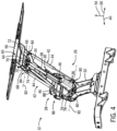
- FIG. 4 is another perspective view of a portion of the hood assembly 12 of FIG. 1 .
- the linear actuator 30 e.g., the body 36 of the linear actuator 30
- the linear actuator pivot joint 76 e.g., second linear actuator pivot joint, linear actuator/lower link pivot joint.
- the linear actuator pivot joint 76 includes a releasable pin 78 that extends through openings in the lower link 32 and the linear actuator 30 (e.g., the body 36 of the linear actuator 30).
- the releasable pin 78 may be secured by any suitable type(s) of fastener(s), such as cotter pin(s), nut(s), clip(s), etc.
- one end of the releasable pin may include a head, and the other end of the releasable pin may include a feature (e.g., groove, threads, aperture, etc.) configured to receive a fastener.
- the fastener may be disengaged from the releasable pin, and the releasable pin may be extracted from the openings in the lower link and the linear actuator, thereby releasing the linear actuator from the lower link.
- the hood may be manually rotated from the closed position to the open position.
- the hood includes opening(s) configured to facilitate access to the releasable pin while the hood is in the closed position.
- the releasable pin may be removed, and the hood may be manually rotated to the open position (e.g., with the assistance of the strut(s)).
- one or more bushing and/or one or more bearings may be disposed about the releasable pin to facilitate rotation of the linear actuator relative to the lower link.
- the opening(s) in the lower link 32 that receive the releasable pin 78 are formed within a mounting portion of the lower link 32.
- the mounting portion may be integrally formed with a body of the lower link, or the mounting portion may be coupled to the body of the lower link (e.g., by a fastener connection, by a welded connection, by an adhesive connection, etc.). While the linear actuator pivot joint 76 includes the releasable pin 78 in the illustrated embodiment, in other embodiments, the linear actuator pivot joint may include any other suitable element(s) (e.g., alone or in combination with the releasable pin) to establish the pivotal connection between the linear actuator and the lower link.
- each strut 42 (e.g., the actuating rod 46 of each strut 42) is pivotally coupled to the lower link 32 at a respective strut pivot joint 80.
- Each strut pivot joint 80 may include any suitable component(s) configured to facilitate rotation of the respective strut 42 relative to the lower link 32 (e.g., including a ball joint).
- the linear actuator 30 (e.g., the body 36 of the linear actuator 30) is pivotally coupled to the lower link 32 at the linear actuator pivot joint 76.
- the strut pivot joints 80 and the linear actuator pivot joint 76 are substantially coaxial.
- substantially coaxial refers to pivot joints having pivot axes 82 that are substantially aligned with one another.
- substantially aligned refers to an angular variation between pivot axes less than a threshold angle and a offset distance between pivot axes less than a threshold offset distance.
- the threshold angle may be 5 degrees, 4 degrees, 3 degrees, 2 degrees, 1 degree, 0.5 degrees, or 0.1 degrees.
- the threshold offset distance may be 15 mm, 10 mm, 5 mm, 1 mm, 0.5 mm, or 0.1 mm.
- each strut 42 (e.g., the body 44 of each strut 42) is pivotally coupled to the upper link 34 at a respective strut pivot joint 84.
- Each strut pivot joint 84 may include any suitable component(s) configured to facilitate rotation of the respective strut 42 relative to the upper link 34 (e.g., including a ball joint).
- the linear actuator 30 (e.g., the actuating rod 38 of the linear actuator 30) is pivotally coupled to the upper link 34 at the first linear actuator pivot joint 66.
- the strut pivot j oints 84 and the first linear actuator pivot j oint 66 are substantially coaxial.
- At least one pivot joint may be angularly and/or translationally offset from at least one other pivot joint.
- the linear actuator may be pivotally coupled to the lower link, and at least one strut may be pivotally coupled to the chassis of the work vehicle.
- the strut pivot joints 84 and the first linear actuator pivot joint 66 are substantially coaxial in the illustrated embodiment, in other embodiments, at least one pivot joint may be angularly and/or translationally offset from at least one other pivot joint.
- the linear actuator may be pivotally coupled to the upper link, and at least one strut may be pivotally coupled to the hood.
- the upper link 34 is pivotally coupled to the lower link 32 by a link interconnection pivot joint 86.
- the link interconnection pivot joint 86 includes a pin 88 that extends through openings in the upper link 34 and the lower link 32.
- the pin 88 may be secured by any suitable type(s) of fastener(s), such as cotter pin(s), nut(s), clip(s), etc.
- one or more bushings and/or one or more bearings may be disposed about the pin to facilitate rotation of the upper link relative to the lower link.
- the link interconnection pivot joint 86 includes the pin 88 in the illustrated embodiment
- the link interconnection pivot joint may include any other suitable element(s) (e.g., alone or in combination with the pin) to establish the pivotal connection between the upper link and the lower link.
- the second linear actuator pivot joint 76 is positioned proximate to the link interconnection pivot joint 86 relative to the longitudinal axis 50, a relatively small extension or retraction of the linear actuator 30 drives the hood to rotate through a relatively large angle, thereby enabling a large opening angle of the hood with a relatively short/compact linear actuator 30.
- each linear actuator pivot joint may be positioned at any suitable location (e.g., relative to the longitudinal axis) relative to the link interconnection pivot joint.
- FIG. 5 is a further perspective view of a portion of the hood assembly 12 of FIG. 1 .
- the hood assembly 12 includes a mount 90 coupled to the chassis of the work vehicle and pivotally coupled to the lower link 32 of the linkage assembly 28. Accordingly, the lower link 32 is pivotally coupled to the chassis of the work vehicle via the mount 90.
- the mount 90 is configured to distribute the load applied by the lift mechanism 26 to the work vehicle chassis over a larger area of the work vehicle chassis, thereby reducing stress within the work vehicle chassis.
- the mount 90 is coupled to the work vehicle chassis by a fastener connection, which includes fastener(s).
- the mount may be coupled to the work vehicle chassis by other suitable types of connection(s) (e.g., alone or in combination with the fastener connection), such as an adhesive connection, a welded connection, other suitable type(s) of connection(s), or a combination thereof.
- suitable types of connection(s) e.g., alone or in combination with the fastener connection
- an adhesive connection e.g., a welded connection, other suitable type(s) of connection(s), or a combination thereof.
- the lower link 32 is pivotally coupled to the mount 90 by a lower link pivot joint 92.
- the lower link pivot joint 92 includes a pin 94 that extends through openings in the lower link 32 and the mount 90.
- the pin 94 may be secured by any suitable type(s) of fastener(s), such as cotter pin(s), nut(s), clip(s), etc.
- one or more bushings and/or one or more bearings may be disposed about the pin to facilitate rotation of the lower link relative to the mount.
- the lower link pivot joint 92 includes the pin 94 in the illustrated embodiment, in other embodiments, the lower link pivot joint may include any other suitable element(s) (e.g., alone or in combination with the pin) to establish the pivotal connection between the lower link and the mount.
- the hood assembly 12 includes the mount 90 in the illustrated embodiment, in other embodiments, the mount may be omitted. In such embodiments, the lower link may be directly pivotally coupled to the work vehicle chassis, or the lower link may be pivotally coupled to the work vehicle chassis via other suitable structure(s).
- FIG. 6 is a perspective view of a portion of the hood assembly 12 of FIG. 1 , in which the hood 22 of the hood assembly 12 is in the closed position.
- the linkage assembly 28 is folded to a relatively small height relative to the vertical axis 54 (e.g., as compared to the linkage assembly 28 while the hood 22 is in the open position), thereby reducing the space utilized by the linkage assembly 28 under the hood 22.
- the lower link 32 has an opening 96 configured to receive a portion of the linear actuator 30 (e.g., a portion of the body 36 of the linear actuator 30) while the hood 22 is in the illustrated closed position.
- the height of the lift mechanism 26 relative to the vertical axis 54 may be reduced.
- the opening in the lower link may be omitted, and the linear actuator may be positioned above the lower link while the hood is in the closed position.
- the upper link 34 has recess(es) 98 configured to receive the mount 90 while the hood 22 is in the illustrated closed position.
- the height of the lift mechanism 26 relative to the vertical axis 54 may be reduced.
- the recess(es) in the upper link may be omitted, and/or the mount may have recess(es) configured to receive the upper link.
- the hood assembly 12 includes a base structure 100 coupled to the work vehicle chassis and configured to support a portion of the linkage assembly 28 while the hood 22 is in the closed position.
- the base structure 100 is coupled to the chassis of the work vehicle by a fastener connection, which includes fastener(s), in the illustrated embodiment.
- the base structure may be coupled to the work vehicle chassis by any other suitable type(s) of connection(s) (e.g., alone or in combination with the fastener connection), such as a welded connection, an adhesive connection, other suitable type(s) of connection(s), or a combination thereof.
- the hood assembly 12 includes stop(s) 102 coupled to the base structure 100.
- the stop(s) 102 are configured to engage the lower link 32 while the hood 22 is in the illustrated closed position, thereby supporting a portion of the linkage assembly 28. As a result, movement of the hood 22 past the closed position (e.g., movement of the hood beyond the closed position along a direction from the open position toward the closed position) may be blocked.
- the stop(s) 102 may be formed from a resilient material, such as rubber and/or a polymeric material, to dissipate the energy associated with contact between the lower link 32 and the stop(s) 102.
- each stop 102 includes a magnet configured to magnetically engage the lower link 32 (e.g., metal structure of the lower link, magnet(s) coupled to the lower link, etc.), thereby coupling the lower link 32 to the base structure 100.
- the hood 22 may be secured in the closed position, thereby substantially reducing or eliminating unintentional opening of the hood 22 (e.g., opening of the hood without use of the linear actuator 30) during operation of the work vehicle.
- the hood 22 may be secured in the closed position by other suitable device(s) (e.g., alone or in combination with the magnet(s)), such as the linear actuator 30, one or more latches (e.g., releasable by the latch release mechanism), other suitable device(s), or a combination thereof.
- suitable device(s) e.g., alone or in combination with the magnet(s)
- the linear actuator 30 one or more latches (e.g., releasable by the latch release mechanism), other suitable device(s), or a combination thereof.
- the magnet(s) of the stop(s) may be omitted.
- the stop(s) may be omitted, and/or movement of the hood past the closed position (e.g., movement of the hood beyond the closed position along a direction from the open position toward the closed position) may be blocked by other suitable structure(s).
- FIG. 7 is another perspective view of a portion of the hood assembly 12 of FIG. 1 .
- the linear actuator 30 e.g., the body 36 of the linear actuator 30
- the releasable pin 78 of the linear actuator pivot joint 76 extends through openings in the lower link 32 and the linear actuator 30 (e.g., the body 36 of the linear actuator 30).
- the hood 22 includes two openings 104 configured to facilitate access to the releasable pin 78 while the hood 22 is in the illustrated closed position.
- the hood 22 includes two openings 104 in the illustrated embodiment, in other embodiments, the hood may include more or fewer openings (e.g., 1, 3, 4, or more).
- an access panel may be disposed over each opening to block dirt and/or debris from passing through the hood while the access panel is engaged with the hood (e.g., closed).
- each access panel may be removable/openable to facilitate access to the releasable pin.
- At least one access panel includes a lip positioned at a first end of the access panel and configured to engage a corresponding slot in the hood.
- the lip may be engaged with the slot, and one or more fasteners may couple a second end of the access panel to the hood. Accordingly, to remove the access panel from the hood, the fasteners may be disengaged, and the lip may be removed from the slot (e.g., by sliding the access panel away from the slot).
- At least one access panel may be selectively coupled to the hood by any other suitable type(s) of releasable connection(s) (e.g., alone or in combination with the fastener(s) and/or the lip/slot connection), such as latch(es), magnet(s), other suitable type(s) of releasable connection(s), or a combination thereof.
- at least one access panel may be configured to rotate and/or translate between open and closed positions to selectively facilitate access to the releasable pin.
- one or more releasable connections may secure the access panel in the closed position.
- at least one access panel may be solid to block dirt and/or debris from passing through the hood while the access panel is engaged with the hood.
- at least one access panel may include aperture(s) to enable air to flow through the hood.
- at least one access panel may be omitted, and the respective opening(s) in the hood may remain open during operation of the work vehicle.
- the access panel(s), if present, may be removed/opened.
- a fastener may then be disengaged from the releasable pin, and the releasable pin may be extracted from the openings in the lower link and the linear actuator, thereby releasing the linear actuator from the lower link.
- the hood may be manually rotated from the closed position to the open position. Accordingly, while the hood is in the illustrated closed position and the linear actuator is non-operational (e.g., due to interruption of electrical power to the electric linear actuator), the releasable pin may be removed, and the hood may be manually rotated to the open position (e.g., with the assistance of the strut(s)).
- releasable pin is used to selectively disconnect an end of the linear actuator in the illustrated embodiment
- other suitable device(s)/element(s) may be used to disconnect an end of the linear actuator to enable the hood to be manually rotated to the open position.
- an end of the linear actuator may be disconnected by uncoupling the mounting portion from the body.
- the end of the linear actuator coupled to the upper link may be disconnected to enable the hood to be manually rotated to the open position.
Landscapes
- Engineering & Computer Science (AREA)
- Mechanical Engineering (AREA)
- Chemical & Material Sciences (AREA)
- Combustion & Propulsion (AREA)
- Transportation (AREA)
- Superstructure Of Vehicle (AREA)
Abstract
A hood assembly (12) for a work vehicle (10) includes a hood (22) and a hood pivot joint (24) configured to pivotally couple the hood (22) to a chassis (18) of the work vehicle (10). The hood pivot joint (24) is configured to enable the hood (22) to rotate between an open position and a closed position. The hood assembly (12) also includes a lift mechanism (26) having a linkage assembly (28) pivotally coupled to the hood (22) and configured to pivotally couple to the chassis (18) of the work vehicle (10). In addition, the lift mechanism (26) includes a linear actuator (30) coupled to the linkage assembly (28). The linear actuator (30) is configured to drive the linkage assembly (28) to rotate the hood (22) between the open and closed positions.
Description
- The present disclosure relates generally to a hood assembly for a work vehicle.
- Certain work vehicles, such as tractors, harvesters, and sprayers, have a hood assembly including a hood configured to facilitate access to certain components of the work vehicle, such as the engine, the cooling system, components of the hydraulic system, etc. Due to the weight of the hood, the hood assembly may include one or more gas struts to offset a portion of the weight of the hood, thereby reducing operator effort in moving the hood from a closed position to an open position. The strut(s) may extend from a chassis of the work vehicle to the hood, and the strut(s) may urge the hood toward the open position. Unfortunately, during cold weather conditions, the force applied by the strut(s) may be reduced. As a result, the force sufficient to drive the hood from the closed position to the open position may be increased, thereby increasing operator effort in opening the hood. In addition, during warm weather conditions, the force applied by the strut(s) may be increased. As a result, the force sufficient to drive the hood from the open position to the closed position may be increased, thereby increasing operator effort in closing the hood.
- This summary is provided to introduce a selection of concepts that are further described below in the detailed description. This summary is not intended to identify key or essential features of the claimed subject matter, nor is it intended to be used as an aid in limiting the scope of the claimed subject matter.
- In certain embodiments, a hood assembly for a work vehicle includes a hood and a hood pivot joint configured to pivotally couple the hood to a chassis of the work vehicle. The hood pivot joint is configured to enable the hood to rotate between an open position and a closed position. The hood assembly also includes a lift mechanism having a linkage assembly pivotally coupled to the hood and configured to pivotally couple to the chassis of the work vehicle. In addition, the lift mechanism includes a linear actuator coupled to the linkage assembly. The linear actuator is configured to drive the linkage assembly to rotate the hood between the open and closed positions.
- These and other features, aspects, and advantages of the present disclosure will become better understood when the following detailed description is read with reference to the accompanying drawings in which like characters represent like parts throughout the drawings, wherein:
-
FIG. 1 is a perspective view of an embodiment of a work vehicle having an embodiment of a hood assembly; -
FIG. 2 is a perspective view of the hood assembly ofFIG. 1 , in which a hood of the hood assembly is in an open position; -
FIG. 3 is a perspective view of a portion of the hood assembly ofFIG. 1 ; -
FIG. 4 is another perspective view of a portion of the hood assembly ofFIG. 1 ; -
FIG. 5 is a further perspective view of a portion of the hood assembly ofFIG. 1 ; -
FIG. 6 is a perspective view of a portion of the hood assembly ofFIG. 1 , in which the hood of the hood assembly is in a closed position; and -
FIG. 7 is another perspective view of a portion of the hood assembly ofFIG. 1 . - One or more specific embodiments of the present disclosure will be described below. In an effort to provide a concise description of these embodiments, all features of an actual implementation may not be described in the specification. It should be appreciated that in the development of any such actual implementation, as in any engineering or design project, numerous implementation-specific decisions must be made to achieve the developers' specific goals, such as compliance with system-related and business-related constraints, which may vary from one implementation to another. Moreover, it should be appreciated that such a development effort might be complex and time consuming, but would nevertheless be a routine undertaking of design, fabrication, and manufacture for those of ordinary skill having the benefit of this disclosure.
-
FIG. 1 is a perspective view of an embodiment of awork vehicle 10 having an embodiment of ahood assembly 12. In the illustrated embodiment, thework vehicle 10 includes acab 14 configured to house an operator. Asteering wheel 16 is disposed within thecab 14 to facilitate control of thework vehicle 10. Thecab 14 may also house additional controls to enable the operator to control various functions of the work vehicle (e.g., movement of a tool coupled to the work vehicle, speed of the work vehicle, etc.). In the illustrated embodiment, thework vehicle 10 includes achassis 18 configured to support an engine, a transmission, thehood assembly 12, other systems of thework vehicle 10, or a combination thereof. In addition, thework vehicle 10 includeswheels 20 configured to be driven by the engine, thereby driving thework vehicle 10 through a field. While thework vehicle 10 includeswheels 20 in the illustrated embodiment, in other embodiments, the work vehicle may include tracks or a combination of wheels and tracks. Furthermore, while thework vehicle 10 is a tractor in the illustrated embodiment, in other embodiments, the work vehicle may be a harvester, a sprayer, a bulldozer, or any other suitable type of work vehicle. - As discussed in detail below, the
hood assembly 12 includes ahood 22 and a hood pivot joint configured to pivotally couple thehood 22 to thechassis 18 of thework vehicle 10. The hood pivot joint is configured to enable thehood 22 to pivot between an open position and a closed position. Rotating thehood 22 to the open position facilitates access to certain component(s) of thework vehicle 10, such as the engine, a cooling system, component(s) of a hydraulic system, other suitable component(s), or a combination thereof. Furthermore, while thehood 22 is in the closed position, access to the component(s) is blocked, and thehood 22 may substantially reduce dirt and/or debris from collecting on the component(s). Furthermore, as discussed in detail below, thehood assembly 12 includes a lift mechanism having a linkage assembly and a linear actuator. The linkage assembly is pivotally coupled to thehood 22 and to thechassis 18 of thework vehicle 10. In addition, the linear actuator is coupled (e.g., pivotally coupled) to the linkage assembly, and the linear actuator is configured to drive the linkage assembly to rotate the hood between the open and closed positions. Because the linear actuator is configured to drive the hood to rotate between the open and closed positions, operator effort associated with manually moving the hood between the open and closed positions may be substantially reduced or eliminated, thereby facilitating the hood opening and closing processes. -
FIG. 2 is a perspective view of thehood assembly 12 ofFIG. 1 , in which thehood 22 of thehood assembly 12 is in the open position. As previously discussed, thehood assembly 12 includes thehood 22 and ahood pivot joint 24. Thehood pivot joint 24 is configured to pivotally couple thehood 22 to the chassis of the work vehicle, thereby enabling thehood 22 to rotate between the illustrated open position and the closed position. Thehood assembly 12 also includes alift mechanism 26 having alinkage assembly 28 and alinear actuator 30. Thelinkage assembly 28 is pivotally coupled to thehood 22 and to the chassis of the work vehicle. In addition, thelinear actuator 30 is coupled (e.g., pivotally coupled) to thelinkage assembly 28, and thelinear actuator 30 is configured to drive thelinkage assembly 28 to rotate thehood 22 between the open and closed positions. Because the linear actuator is configured to drive the hood to rotate between the open and closed positions, operator effort associated with manually moving the hood between the open and closed positions may be substantially reduced or eliminated, thereby facilitating the hood opening and closing processes. In addition, because thelift mechanism 26 drives thehood 22 to rotate between the open and closed positions, the opening angle of thehood 22 may not be limited by the reach of an operator, thereby facilitating a larger opening angle, which may enhance access to the component(s) under thehood 22. - In the illustrated embodiment, the
linkage assembly 28 has alower link 32 and anupper link 34. Thelower link 32 is pivotally coupled to the chassis of the work vehicle, and theupper link 34 is pivotally coupled to thehood 22. In addition, thelower link 32 and theupper link 34 are pivotally coupled to one another. Furthermore, in the illustrated embodiment, thelinear actuator 30 is pivotally coupled to thelower link 32 and to theupper link 34. Accordingly, extension of thelinear actuator 30 drives the lower and upper links to rotate away from one another, thereby driving thehood 22 to rotate toward the illustrated open position. In addition, retraction of thelinear actuator 30 drives the lower and upper links to pivot toward one another, thereby driving thehood 22 to rotate toward the closed position. Due to the coupling locations of thelinear actuator 30, a relatively small extension or retraction of thelinear actuator 30 drives thehood 22 to rotate through a relatively large angle, thereby enabling a large opening angle of thehood 22 with a relatively short/compactlinear actuator 30. - While the
linear actuator 30 is pivotally coupled to thelower link 32 and to theupper link 34 in the illustrated embodiment, in other embodiments, the linear actuator may be coupled to other suitable structure(s) to drive the hood to rotate between the open and closed positions. For example, in certain embodiments, the linear actuator may be pivotally coupled to the chassis of the work vehicle (e.g., directly or via a mount/mounting structure). Additionally or alternatively, in certain embodiments, the linear actuator may be pivotally coupled to the hood of the hood assembly (e.g., directly or via a mount/mounting structure). For example, in certain embodiments, the linear actuator may be pivotally coupled to the chassis and to the hood, the linear actuator may be pivotally coupled to the lower link and to the hood, or the linear actuator may be pivotally coupled to the chassis and to the upper link. Furthermore, while thelift mechanism 26 includes a singlelinear actuator 30 in the illustrated embodiment, in other embodiments, the lift mechanism may include multiple linear actuators (e.g., 2, 3, 4, or more), and each linear actuator may be pivotally coupled to any of the structures disclosed above and/or to any other suitable structure(s). In addition, in certain embodiments, the linear actuator may be omitted. - In the illustrated embodiment, the
linear actuator 30 is an electric linear actuator having abody 36 and anactuating rod 38. Thebody 36 is configured to house a driver, such as an electric motor, and the driver is configured to drive the actuatingrod 38 to move relative to thebody 36, thereby driving thelinear actuator 30 to extend and retract. In the illustrated embodiment, thebody 36 of thelinear actuator 30 is pivotally coupled to thelower link 32, and theactuating rod 38 is pivotally coupled to theupper link 34. However, in other embodiments, the body of the linear actuator may be pivotally coupled to the upper link or to another suitable structure, and the actuating rod may be pivotally coupled to the lower link or to another suitable structure. While the linear actuator is an electric linear actuator in the illustrated embodiment, in other embodiments, the linear actuator may be a pneumatic linear actuator (e.g., pneumatic cylinder, air bag, etc.), a hydraulic linear actuator (e.g., hydraulic cylinder, etc.), or another suitable type of linear actuator. Furthermore, while the lift mechanism includes a linear actuator in the illustrated embodiment, in other embodiments, the lift mechanism may include a rotary actuator (e.g., electric motor, pneumatic motor, hydraulic motor, etc.) coupled to the upper and lower links and configured to drive the upper and lower links to rotate relative to one another. - In the illustrated embodiment, each link of the
linkage assembly 28 is substantially rigid. Each link may be formed from any suitable material to establish the substantially rigid link, such as steel, aluminum, polymeric material, composite material (e.g., fiberglass, carbon fiber, fiber reinforced plastic, etc.), other suitable material(s), or a combination thereof. Furthermore, while thelinkage assembly 28 includes two links (e.g., only two links) in the illustrated embodiment, in other embodiments, the linkage assembly may include one or more additional links. For example, in certain embodiments, the linkage assembly may include 3, 4, 5, 6, or more links, and the links may be pivotally coupled to one another. - In the illustrated embodiment, the
lower link 32 is configured to rotate about an axis substantially parallel to alateral axis 40 of thehood assembly 12 relative to the chassis of the work vehicle. In addition, theupper link 34 is configured to rotate about an axis substantially parallel to thelateral axis 40 relative to thehood 22. Furthermore, thelower link 32 and theupper link 34 are configured to rotate about an axis substantially parallel to thelateral axis 40 relative to one another. However, in other embodiments, the links may be configured to rotate about other suitable axes. For example, in certain embodiments, the links may be configured to rotate about respective axes substantially parallel to a longitudinal axis of the hood assembly, or the links may be configured to rotate about respective axes substantially parallel to an axis angled relative to the lateral axis and/or the longitudinal axis of the hood assembly. - In the illustrated embodiment, the
lift mechanism 26 includes twostruts 42 configured to urge thehood 22 toward the open position, thereby reducing the load on thelinear actuator 30. Accordingly, a smaller/less powerfullinear actuator 30 may be used to drive thehood 22 to rotate between the open and closed positions, thereby reducing the cost of thelift mechanism 26. In certain embodiments, eachstrut 42 is a gas strut (e.g., pneumatic strut). However, in other embodiments, at least one strut may be a hydraulic strut, a mechanical strut (e.g., including a spring), or another suitable type of strut. In the illustrated embodiment, thestruts 42 are positioned on opposite lateral sides of the lower and upper links (e.g., opposite sides along the lateral axis 40). However, in other embodiments, the struts may be positioned on the same lateral side of the lower and upper links, or at least one strut may be positioned between the lower and upper links along the lateral axis. Furthermore, while thelift mechanism 26 includes twostruts 42 in the illustrated embodiment, in other embodiments, the lift mechanism may include more or fewer struts (e.g., 0, 1, 3, 4, 5, 6, or more), and the struts may be positioned in any suitable location(s). For example, in certain embodiments, the struts may be omitted. Furthermore, in certain embodiments, the lift mechanism may include other suitable biasing element(s) (e.g., alone or in combination with the strut(s)) configured to urge the hood toward the open position, such as coil spring(s) positioned at the hood pivot joint. - In the illustrated embodiment, each
strut 42 is pivotally coupled to thelower link 32 and to theupper link 34. Accordingly, thestruts 42 urge the lower and upper links to rotate away from one another, thereby urging thehood 22 to rotate toward the illustrated open position. Furthermore, in the illustrated embodiment, eachstrut 42 includes abody 44 and anactuating rod 46 extending from thebody 44. The actuatingrod 46 is urged way from the body 44 (e.g., due to air pressure, hydraulic pressure, etc.), thereby urging thestrut 42 to extend. In the illustrated embodiment, thebody 44 of eachstrut 42 is pivotally coupled to theupper link 34, and theactuating rod 46 of eachstrut 42 is pivotally coupled to thelower link 32. However, in other embodiments, the body of at least one strut may be pivotally coupled to the lower link, and the corresponding actuating rod(s) may be pivotally coupled to the upper link. Furthermore, in certain embodiments, at least one strut may not include a body and/or an actuating rod, such as a mechanical strut (e.g., including a spring). - While each
strut 42 is pivotally coupled to thelower link 32 and to theupper link 34 in the illustrated embodiment, in other embodiments, at least one strut may be coupled to other suitable structure(s) to urge the hood to rotate toward the open position. For example, in certain embodiments, at least one strut may be pivotally coupled to the chassis of the work vehicle (e.g., directly or via a mount/mounting structure). Additionally or alternatively, in certain embodiments, at least one strut may be pivotally coupled to the hood of the hood assembly (e.g., directly or via a mount/mounting structure). For example, in certain embodiments, at least one strut may be pivotally coupled to the chassis and to the hood, at least one strut may be pivotally coupled to the lower link and to the hood, at least one strut may be pivotally coupled to the chassis and to the upper link, or a combination thereof. - In the illustrated embodiment, the hood pivot joint 24 is positioned at a
rear portion 48 of thehood 22 relative to alongitudinal axis 50 of thehood assembly 12. In addition, the linkage assembly 28 (e.g., theupper link 34 of the linkage assembly 28) is pivotally coupled to thehood 22 at afront portion 52 of thehood 22 relative to thelongitudinal axis 50. Accordingly, thelift mechanism 26 is configured to drive thefront portion 52 of thehood 22 upwardly relative to avertical axis 54 of thehood assembly 12 to rotate thehood 22 to the open position, and thelift mechanism 26 is configured to drive thefront portion 52 of thehood 22 downwardly relative to thevertical axis 54 to rotate thehood 22 to the closed position. Because the hood pivot joint 24 is positioned at arear portion 48 of thehood 22 and thelinkage assembly 28 is pivotally coupled to thefront portion 52 of thehood 22, the longitudinal stability of thehood 22 may be enhanced (e.g., as compared to a hood assembly in which the pivot joint is positioned at the rear portion of the hood and the linkage assembly is pivotally coupled to the rear portion of the hood). While the hood pivot joint 24 is positioned at therear portion 48 of thehood 22 and thelinkage assembly 28 is pivotally coupled to thefront portion 52 of thehood 22 in the illustrated embodiment, in other embodiments, the hood pivot joint may be positioned at another suitable portion of the hood and the linkage assembly may be pivotally coupled to another suitable portion of the hood. For example, in certain embodiments, the hood pivot joint may be positioned at the front portion of the hood, and the linkage assembly may be pivotally coupled to the rear portion of the hood. Furthermore, in certain embodiments, the hood pivot joint may be positioned at the rear portion of the hood, and the linkage assembly may be pivotally coupled to the rear portion of the hood. In addition, in certain embodiments, the hood pivot joint may be positioned at the front portion of the hood, and the linkage assembly may be pivotally coupled to the front portion of the hood. With regard to the front and rear portions of the hood, the front portion is positioned forward of a longitudinal center of the hood (e.g., center of the hood along the longitudinal axis while the hood is in the closed position), and the rear portion is positioned rearward of the longitudinal center of the hood (e.g., center of the hood along the longitudinal axis while the hood is in the closed position). - Furthermore, in the illustrated embodiment, the
lift mechanism 26 includes aswitch 53 communicatively coupled to the linear actuator 30 (e.g., electric linear actuator). Theswitch 53 is configured to control thelinear actuator 30 to move thehood 22 from the illustrated open position to the closed position and to move thehood 22 from the closed position to the illustrated open position based on operator input. Theswitch 53 may be located at or near thehood 22 on an exterior of the work vehicle, or theswitch 53 may be located within the cab of the work vehicle. Furthermore, in certain embodiments, theswitch 53 may be integrated with alatch release mechanism 55, which is configured to release latch(es) that secure thehood 22 in the closed position. For example, a handle of thelatch release mechanism 55 may be located within the cab of the work vehicle, and the operator may activate thelatch release mechanism 55 using the handle to disengage the latch(es) and control thelinear actuator 30 to move the hood from the closed position to the open position. In addition, the operator may use the handle to activate thelatch release mechanism 55 to control thelinear actuator 30 to move the hood from the open position to the closed position. -
FIG. 3 is a perspective view of a portion of thehood assembly 12 ofFIG. 1 . In the illustrated embodiment, thehood assembly 12 includes asupport structure 56 coupled to thehood 22 and pivotally coupled to theupper link 34 of thelinkage assembly 28. Accordingly, theupper link 34 is pivotally coupled to thehood 22 via thesupport structure 56. Thesupport structure 56 is configured to enhance the lateral stability of the hood 22 (e.g., stability of thehood 22 along the lateral axis 40), thereby reducing rotation/wobble of the hood 22 (e.g., generally about the longitudinal axis 50) while thehood 22 is in the illustrated open position. In addition, thesupport structure 56 is configured to distribute the load applied by thelift mechanism 26 to thehood 22 over a larger area of thehood 22, thereby reducing stress within thehood 22. In the illustrated embodiment, thesupport structure 56 is coupled to thehood 22 by a fastener connection, which includes fastener(s) 58. However, in other embodiments, the support structure may be coupled to the hood by other suitable types of connection(s) (e.g., alone or in combination with the fastener connection), such as an adhesive connection, a welded connection, other suitable type(s) of connection(s), or a combination thereof. - As illustrated, the
upper link 34 is pivotally coupled to thesupport structure 56 by an upper link pivot joint 60. In the illustrated embodiment, the upper link pivot joint 60 includes apin 62 that extends through openings in theupper link 34 and thesupport structure 56. Thepin 62 may be secured by any suitable type(s) of fastener(s), such as cotter pin(s), nut(s), clip(s), etc. Furthermore, in certain embodiments, one or more bushings and/or one or more bearings may be disposed about the pin to facilitate rotation of the upper link relative to the support structure. While the upper link pivot joint 60 includes thepin 62 in the illustrated embodiment, in other embodiments, the upper link pivot joint may include any other suitable element(s) (e.g., alone or in combination with the pin) to establish the pivotal connection between the upper link and the support structure. Furthermore, while thehood assembly 12 includes thesupport structure 56 in the illustrated embodiment, in other embodiments, the support structure may be omitted. In such embodiments, the upper link may be directly pivotally coupled to the hood, or the upper link may be pivotally coupled to the hood via other suitable structure(s). - In the illustrated embodiment, the
lift mechanism 26 includes apivot assembly 64 that forms a linear actuator pivot joint 66 (e.g., first linear actuator pivot joint, linear actuator/upper link pivot joint) between the linear actuator 30 (e.g., the actuatingrod 38 of the linear actuator 30) and theupper link 34. Thepivot assembly 64 pivotally couples the linear actuator 30 (e.g., the actuatingrod 38 of the linear actuator 30) to theupper link 34, such that the linear actuator 30 (e.g., the actuatingrod 38 of the linear actuator 30) is pivotally coupled to theupper link 34 at the linear actuator pivot joint 66. In the illustrated embodiment, thepivot assembly 64 includes apin 68 that extends through openings in the linear actuator 30 (e.g., the actuatingrod 38 of the linear actuator 30) and thepivot assembly 64. Thepin 68 may be secured by any suitable type(s) of fastener(s), such as cotter pin(s), nut(s), clip(s), etc. While thepivot assembly 64 includes thepin 68 in the illustrated embodiment, in other embodiments, the pivot assembly may include any other suitable element(s) (e.g., alone or in combination with the pin) to establish the pivotal connection between the upper link and the linear actuator. - Furthermore, in the illustrated embodiment, the
pivot assembly 64 includesresilient bushings 70 configured to facilitate movement of an end of thelinear actuator 30 relative to theupper link 34, thereby enabling thelinear actuator 30 to fully retract while the hood is in the closed position. For example, thelinear actuator 30 may be controlled to fully retract to rotate the hood from the open position to the closed position. Once the hood is closed, further rotation of the upper and lower links is blocked. However, the linear actuator may not be fully retracted (e.g., due to tolerance stacking of components, thermal expansion/contraction of component(s), etc.). Accordingly, theresilient bushings 70 enable the linear actuator to fully retract while the hood is in the closed position. In the illustrated embodiment, theresilient bushings 70 are disposed between thepin 68 and asupport structure 72 of thepivot assembly 64. While thepivot assembly 64 includes tworesilient bushings 70 in the illustrated embodiment, in other embodiments, the pivot assembly may include more or fewer resilient bushings (e.g., based on the configuration of the pivot assembly). Furthermore, in embodiments of the pivot assembly in which the pin is omitted, the resilient bushing(s) may be disposed about the other suitable element(s) configured to establish the pivotal connection between the upper link and the linear actuator. Furthermore, in certain embodiments, the resilient bushing(s) may be omitted, and/or the pivot assembly may include bearing(s). - In the illustrated embodiment, the
support structure 72 of thepivot assembly 64 is coupled to theupper link 34 by a fastener connection, which includes fastener(s) 74. However, in other embodiments, the support structure of the pivot assembly may be coupled to the upper link by other suitable types of connection(s) (e.g., alone or in combination with the fastener connection), such as an adhesive connection, a welded connection, other suitable type(s) of connection(s), or a combination thereof. Furthermore, in certain embodiments, the support structure of the pivot assembly may be integrally formed with the upper link. -
FIG. 4 is another perspective view of a portion of thehood assembly 12 ofFIG. 1 . As illustrated, the linear actuator 30 (e.g., thebody 36 of the linear actuator 30) is pivotally coupled to thelower link 32 at a linear actuator pivot joint 76 (e.g., second linear actuator pivot joint, linear actuator/lower link pivot joint). In the illustrated embodiment, the linear actuator pivot joint 76 includes areleasable pin 78 that extends through openings in thelower link 32 and the linear actuator 30 (e.g., thebody 36 of the linear actuator 30). Thereleasable pin 78 may be secured by any suitable type(s) of fastener(s), such as cotter pin(s), nut(s), clip(s), etc. For example, one end of the releasable pin may include a head, and the other end of the releasable pin may include a feature (e.g., groove, threads, aperture, etc.) configured to receive a fastener. To remove the releasable pin, the fastener may be disengaged from the releasable pin, and the releasable pin may be extracted from the openings in the lower link and the linear actuator, thereby releasing the linear actuator from the lower link. As a result, the hood may be manually rotated from the closed position to the open position. As discussed in detail below, the hood includes opening(s) configured to facilitate access to the releasable pin while the hood is in the closed position. Accordingly, while the hood is in the closed position and the linear actuator is non-operational (e.g., due to interruption of electrical power to the electric linear actuator), the releasable pin may be removed, and the hood may be manually rotated to the open position (e.g., with the assistance of the strut(s)). In certain embodiments, one or more bushing and/or one or more bearings may be disposed about the releasable pin to facilitate rotation of the linear actuator relative to the lower link. Furthermore, the opening(s) in thelower link 32 that receive thereleasable pin 78 are formed within a mounting portion of thelower link 32. The mounting portion may be integrally formed with a body of the lower link, or the mounting portion may be coupled to the body of the lower link (e.g., by a fastener connection, by a welded connection, by an adhesive connection, etc.). While the linear actuator pivot joint 76 includes thereleasable pin 78 in the illustrated embodiment, in other embodiments, the linear actuator pivot joint may include any other suitable element(s) (e.g., alone or in combination with the releasable pin) to establish the pivotal connection between the linear actuator and the lower link. - In the illustrated embodiment, each strut 42 (e.g., the actuating
rod 46 of each strut 42) is pivotally coupled to thelower link 32 at a respective strut pivot joint 80. Each strut pivot joint 80 may include any suitable component(s) configured to facilitate rotation of therespective strut 42 relative to the lower link 32 (e.g., including a ball joint). In addition, as previously discussed, the linear actuator 30 (e.g., thebody 36 of the linear actuator 30) is pivotally coupled to thelower link 32 at the linear actuator pivot joint 76. In the illustrated embodiment, the strut pivot joints 80 and the linear actuator pivot joint 76 are substantially coaxial. As used herein with regard to pivot joints, "substantially coaxial" refers to pivot joints having pivot axes 82 that are substantially aligned with one another. Furthermore, as used herein with regard to pivot axes, "substantially aligned" refers to an angular variation between pivot axes less than a threshold angle and a offset distance between pivot axes less than a threshold offset distance. In certain embodiments, the threshold angle may be 5 degrees, 4 degrees, 3 degrees, 2 degrees, 1 degree, 0.5 degrees, or 0.1 degrees. Furthermore, in certain embodiments, the threshold offset distance may be 15 mm, 10 mm, 5 mm, 1 mm, 0.5 mm, or 0.1 mm. - Furthermore, in the illustrated embodiment, each strut 42 (e.g., the
body 44 of each strut 42) is pivotally coupled to theupper link 34 at a respective strut pivot joint 84. Each strut pivot joint 84 may include any suitable component(s) configured to facilitate rotation of therespective strut 42 relative to the upper link 34 (e.g., including a ball joint). In addition, as previously discussed, the linear actuator 30 (e.g., the actuatingrod 38 of the linear actuator 30) is pivotally coupled to theupper link 34 at the first linear actuator pivot joint 66. In the illustrated embodiment, the strut pivot j oints 84 and the first linear actuatorpivot j oint 66 are substantially coaxial. While the strut pivot joints 80 and the second linear actuator pivot joint 76 are coaxial in the illustrated embodiment, in other embodiments, at least one pivot joint may be angularly and/or translationally offset from at least one other pivot joint. For example, the linear actuator may be pivotally coupled to the lower link, and at least one strut may be pivotally coupled to the chassis of the work vehicle. Furthermore, while the strut pivot joints 84 and the first linear actuator pivot joint 66 are substantially coaxial in the illustrated embodiment, in other embodiments, at least one pivot joint may be angularly and/or translationally offset from at least one other pivot joint. For example, the linear actuator may be pivotally coupled to the upper link, and at least one strut may be pivotally coupled to the hood. - As illustrated, the
upper link 34 is pivotally coupled to thelower link 32 by a link interconnection pivot joint 86. In the illustrated embodiment, the link interconnection pivot joint 86 includes apin 88 that extends through openings in theupper link 34 and thelower link 32. Thepin 88 may be secured by any suitable type(s) of fastener(s), such as cotter pin(s), nut(s), clip(s), etc. Furthermore, in certain embodiments, one or more bushings and/or one or more bearings may be disposed about the pin to facilitate rotation of the upper link relative to the lower link. While the link interconnection pivot joint 86 includes thepin 88 in the illustrated embodiment, in other embodiments, the link interconnection pivot joint may include any other suitable element(s) (e.g., alone or in combination with the pin) to establish the pivotal connection between the upper link and the lower link. Furthermore, because the second linear actuator pivot joint 76 is positioned proximate to the link interconnection pivot joint 86 relative to thelongitudinal axis 50, a relatively small extension or retraction of thelinear actuator 30 drives the hood to rotate through a relatively large angle, thereby enabling a large opening angle of the hood with a relatively short/compactlinear actuator 30. However, in other embodiments, each linear actuator pivot joint may be positioned at any suitable location (e.g., relative to the longitudinal axis) relative to the link interconnection pivot joint. -
FIG. 5 is a further perspective view of a portion of thehood assembly 12 ofFIG. 1 . In the illustrated embodiment, thehood assembly 12 includes amount 90 coupled to the chassis of the work vehicle and pivotally coupled to thelower link 32 of thelinkage assembly 28. Accordingly, thelower link 32 is pivotally coupled to the chassis of the work vehicle via themount 90. Themount 90 is configured to distribute the load applied by thelift mechanism 26 to the work vehicle chassis over a larger area of the work vehicle chassis, thereby reducing stress within the work vehicle chassis. In the illustrated embodiment, themount 90 is coupled to the work vehicle chassis by a fastener connection, which includes fastener(s). However, in other embodiments, the mount may be coupled to the work vehicle chassis by other suitable types of connection(s) (e.g., alone or in combination with the fastener connection), such as an adhesive connection, a welded connection, other suitable type(s) of connection(s), or a combination thereof. - As illustrated, the
lower link 32 is pivotally coupled to themount 90 by a lower link pivot joint 92. In the illustrated embodiment, the lower link pivot joint 92 includes apin 94 that extends through openings in thelower link 32 and themount 90. Thepin 94 may be secured by any suitable type(s) of fastener(s), such as cotter pin(s), nut(s), clip(s), etc. Furthermore, in certain embodiments, one or more bushings and/or one or more bearings may be disposed about the pin to facilitate rotation of the lower link relative to the mount. While the lower link pivot joint 92 includes thepin 94 in the illustrated embodiment, in other embodiments, the lower link pivot joint may include any other suitable element(s) (e.g., alone or in combination with the pin) to establish the pivotal connection between the lower link and the mount. Furthermore, while thehood assembly 12 includes themount 90 in the illustrated embodiment, in other embodiments, the mount may be omitted. In such embodiments, the lower link may be directly pivotally coupled to the work vehicle chassis, or the lower link may be pivotally coupled to the work vehicle chassis via other suitable structure(s). -
FIG. 6 is a perspective view of a portion of thehood assembly 12 ofFIG. 1 , in which thehood 22 of thehood assembly 12 is in the closed position. As illustrated, with thehood 22 in the closed position, thelinkage assembly 28 is folded to a relatively small height relative to the vertical axis 54 (e.g., as compared to thelinkage assembly 28 while thehood 22 is in the open position), thereby reducing the space utilized by thelinkage assembly 28 under thehood 22. Furthermore, in the illustrated embodiment, thelower link 32 has anopening 96 configured to receive a portion of the linear actuator 30 (e.g., a portion of thebody 36 of the linear actuator 30) while thehood 22 is in the illustrated closed position. As a result, the height of thelift mechanism 26 relative to thevertical axis 54 may be reduced. However, in other embodiments, the opening in the lower link may be omitted, and the linear actuator may be positioned above the lower link while the hood is in the closed position. In addition, in the illustrated embodiment, theupper link 34 has recess(es) 98 configured to receive themount 90 while thehood 22 is in the illustrated closed position. As a result, the height of thelift mechanism 26 relative to thevertical axis 54 may be reduced. However, in other embodiments, the recess(es) in the upper link may be omitted, and/or the mount may have recess(es) configured to receive the upper link. - In the illustrated embodiment, the
hood assembly 12 includes abase structure 100 coupled to the work vehicle chassis and configured to support a portion of thelinkage assembly 28 while thehood 22 is in the closed position. Thebase structure 100 is coupled to the chassis of the work vehicle by a fastener connection, which includes fastener(s), in the illustrated embodiment. However, in other embodiments, the base structure may be coupled to the work vehicle chassis by any other suitable type(s) of connection(s) (e.g., alone or in combination with the fastener connection), such as a welded connection, an adhesive connection, other suitable type(s) of connection(s), or a combination thereof. Furthermore, in the illustrated embodiment, thehood assembly 12 includes stop(s) 102 coupled to thebase structure 100. The stop(s) 102 are configured to engage thelower link 32 while thehood 22 is in the illustrated closed position, thereby supporting a portion of thelinkage assembly 28. As a result, movement of thehood 22 past the closed position (e.g., movement of the hood beyond the closed position along a direction from the open position toward the closed position) may be blocked. In certain embodiments, the stop(s) 102 may be formed from a resilient material, such as rubber and/or a polymeric material, to dissipate the energy associated with contact between thelower link 32 and the stop(s) 102. - In certain embodiments, each
stop 102 includes a magnet configured to magnetically engage the lower link 32 (e.g., metal structure of the lower link, magnet(s) coupled to the lower link, etc.), thereby coupling thelower link 32 to thebase structure 100. As a result, thehood 22 may be secured in the closed position, thereby substantially reducing or eliminating unintentional opening of the hood 22 (e.g., opening of the hood without use of the linear actuator 30) during operation of the work vehicle. In certain embodiments, thehood 22 may be secured in the closed position by other suitable device(s) (e.g., alone or in combination with the magnet(s)), such as thelinear actuator 30, one or more latches (e.g., releasable by the latch release mechanism), other suitable device(s), or a combination thereof. For example, in certain embodiments, the magnet(s) of the stop(s) may be omitted. In addition, in certain embodiments, the stop(s) may be omitted, and/or movement of the hood past the closed position (e.g., movement of the hood beyond the closed position along a direction from the open position toward the closed position) may be blocked by other suitable structure(s). -
FIG. 7 is another perspective view of a portion of thehood assembly 12 ofFIG. 1 . As previously discussed, the linear actuator 30 (e.g., thebody 36 of the linear actuator 30) is pivotally coupled to thelower link 32 at the linear actuator pivot joint 76. In addition, thereleasable pin 78 of the linear actuator pivot joint 76 extends through openings in thelower link 32 and the linear actuator 30 (e.g., thebody 36 of the linear actuator 30). Furthermore, in the illustrated embodiment, thehood 22 includes twoopenings 104 configured to facilitate access to thereleasable pin 78 while thehood 22 is in the illustrated closed position. While thehood 22 includes twoopenings 104 in the illustrated embodiment, in other embodiments, the hood may include more or fewer openings (e.g., 1, 3, 4, or more). Furthermore, in certain embodiments, an access panel may be disposed over each opening to block dirt and/or debris from passing through the hood while the access panel is engaged with the hood (e.g., closed). In addition, each access panel may be removable/openable to facilitate access to the releasable pin. - In certain embodiments, at least one access panel includes a lip positioned at a first end of the access panel and configured to engage a corresponding slot in the hood. In such embodiments, the lip may be engaged with the slot, and one or more fasteners may couple a second end of the access panel to the hood. Accordingly, to remove the access panel from the hood, the fasteners may be disengaged, and the lip may be removed from the slot (e.g., by sliding the access panel away from the slot). Furthermore, in certain embodiments, at least one access panel may be selectively coupled to the hood by any other suitable type(s) of releasable connection(s) (e.g., alone or in combination with the fastener(s) and/or the lip/slot connection), such as latch(es), magnet(s), other suitable type(s) of releasable connection(s), or a combination thereof. In addition, in certain embodiments, at least one access panel may be configured to rotate and/or translate between open and closed positions to selectively facilitate access to the releasable pin. In such embodiments, while the access panel is closed, one or more releasable connections (e.g., magnet(s), latch(es), etc.) may secure the access panel in the closed position. In addition, in certain embodiments, at least one access panel may be solid to block dirt and/or debris from passing through the hood while the access panel is engaged with the hood. Additionally or alternatively, at least one access panel may include aperture(s) to enable air to flow through the hood. Furthermore, in certain embodiments, at least one access panel may be omitted, and the respective opening(s) in the hood may remain open during operation of the work vehicle.
- To remove the releasable pin, the access panel(s), if present, may be removed/opened. A fastener may then be disengaged from the releasable pin, and the releasable pin may be extracted from the openings in the lower link and the linear actuator, thereby releasing the linear actuator from the lower link. As a result, the hood may be manually rotated from the closed position to the open position. Accordingly, while the hood is in the illustrated closed position and the linear actuator is non-operational (e.g., due to interruption of electrical power to the electric linear actuator), the releasable pin may be removed, and the hood may be manually rotated to the open position (e.g., with the assistance of the strut(s)). While the releasable pin is used to selectively disconnect an end of the linear actuator in the illustrated embodiment, in other embodiments, other suitable device(s)/element(s) may be used to disconnect an end of the linear actuator to enable the hood to be manually rotated to the open position. For example, in embodiments in which the mounting portion of the lower link is coupled to the body of the lower link, an end of the linear actuator may be disconnected by uncoupling the mounting portion from the body. Furthermore, in certain embodiments, the end of the linear actuator coupled to the upper link may be disconnected to enable the hood to be manually rotated to the open position.
- While only certain features have been illustrated and described herein, many modifications and changes will occur to those skilled in the art.
Claims (15)
- A hood assembly (12) for a work vehicle (10), comprising:a hood (22);a hood pivot joint (24) configured to pivotally couple the hood (22) to a chassis (18) of the work vehicle (10), wherein the hood pivot joint (24) is configured to enable the hood (22) to rotate between an open position and a closed position; anda lift mechanism (26), comprising:a linkage assembly (28) pivotally coupled to the hood (22) and configured to pivotally couple to the chassis (18) of the work vehicle (10); anda linear actuator (30) coupled to the linkage assembly (28), wherein the linear actuator (30) is configured to drive the linkage assembly (28) to rotate the hood (22) between the open and closed positions.
- The hood assembly (12) of claim 1, wherein the linkage assembly (28) comprises:a lower link (32) configured to pivotally couple to the chassis (18) of the work vehicle (10); andan upper link (34) pivotally coupled to the hood (22), wherein the lower link (32) and the upper link (34) are pivotally coupled to one another.
- The hood assembly (12) of claim 2, wherein the hood pivot joint (24) is positioned at a rear portion of the hood (22).
- The hood assembly (12) of any of claims 2 or 3, wherein the linear actuator (30) is pivotally coupled to the lower link (32) and to the upper link (34).
- The hood assembly (12) of claim 4, wherein the lift mechanism (26) comprises a pivot assembly (64) configured to pivotally couple the linear actuator (30) to the upper link (34), and the pivot assembly (64) comprises a resilient bushing (70).
- The hood assembly (12) of any of claims 2 to 5, wherein the lift mechanism (26) comprises a strut (42) pivotally coupled to the lower link (32) and to the upper link (34).
- The hood assembly (12) of any preceding claim, wherein the lift mechanism (26) comprises a pin (88) configured to selectively release the linear actuator (30) to enable the hood (22) to be manually rotated from the closed position to the open position, and the hood (22) has an opening (96) configured to facilitate access to the pin (88) while the hood (22) is in the closed position.
- The hood assembly (12) of any preceding claim, wherein the linear actuator (30) comprises an electric linear actuator.
- The hood assembly (12) of any preceding claim, wherein the lift mechanism (26) comprises a switch (53) communicatively coupled to the linear actuator (30), wherein the switch (53) is configured to control the linear actuator (30) to drive the linkage assembly (28) to rotate the hood (22) between the open and closed positions, and the switch (53) is integrated within a latch release mechanism (55).
- The hood assembly (12) of any of claims 6 to 9, wherein the strut (42) is pivotally coupled to the lower link (32) at a strut pivot joint (80), the linear actuator (30) is pivotally coupled to the lower link (32) at a linear actuator pivot joint (24), and the strut pivot joint (80) and the linear actuator pivot joint (24) are substantially coaxial; and
wherein the strut (42) is pivotally coupled to the upper link (34) at a strut pivot joint (80), the linear actuator (30) is pivotally coupled to the upper link (34) at a linear actuator pivot joint (24), and the strut pivot joint (80) and the linear actuator pivot joint (24) are substantially coaxial. - The hood assembly (12) of any of claims 2 to 10, wherein the lower link (32) has an opening (96) configured to receive a portion of the linear actuator (30) while the hood (22) is in the closed position.
- The hood assembly (12) of any of claims 2 to 11, wherein the linear actuator (30) is pivotally coupled to the lower link (32) at a linear actuator pivot joint (24), the linear actuator pivot joint (24) comprises a pin (88) configured to selectively release the linear actuator (30) from the lower link (32) to enable the hood (22) to be manually rotated from the closed position to the open position, and the hood (22) has an opening (96) configured to facilitate access to the pin (88) while the hood (22) is in the closed position.
- The hood assembly (12) of any of claims 2 to 12, wherein the upper link (34) has a recess (98) configured to receive a mount (90) configured to couple to the chassis (18) while the hood (22) is in the closed position.
- The hood assembly (12) of any of claims 2 to 13, wherein the lift mechanism (26) comprises a pivot assembly (64) configured to pivotally couple the linear actuator (30) to the upper link (34), and the pivot assembly (64) comprises a resilient bushing (70).
- The hood assembly (12) of any of claims 6 to 15, wherein the lift mechanism (26) comprises a second strut (42) pivotally coupled to the lower link (32) and to the upper link (34), wherein the first and second struts (42) are positioned on opposite lateral sides of the upper and lower links.
Applications Claiming Priority (1)
| Application Number | Priority Date | Filing Date | Title |
|---|---|---|---|
| US18/072,198 US12391316B2 (en) | 2022-11-30 | 2022-11-30 | Hood assembly for a work vehicle |
Publications (1)
| Publication Number | Publication Date |
|---|---|
| EP4379180A1 true EP4379180A1 (en) | 2024-06-05 |
Family
ID=89029738
Family Applications (1)
| Application Number | Title | Priority Date | Filing Date |
|---|---|---|---|
| EP23213543.4A Pending EP4379180A1 (en) | 2022-11-30 | 2023-11-30 | Hood assembly for a work vehicle |
Country Status (3)
| Country | Link |
|---|---|
| US (1) | US12391316B2 (en) |
| EP (1) | EP4379180A1 (en) |
| CN (1) | CN118107667A (en) |
Families Citing this family (2)
| Publication number | Priority date | Publication date | Assignee | Title |
|---|---|---|---|---|
| JP2023103180A (en) * | 2022-01-13 | 2023-07-26 | フェラーリ エッセ.ピー.アー. | automotive hood |
| US12391316B2 (en) * | 2022-11-30 | 2025-08-19 | Cnh Industrial America Llc | Hood assembly for a work vehicle |
Citations (3)
| Publication number | Priority date | Publication date | Assignee | Title |
|---|---|---|---|---|
| DE10307120A1 (en) * | 2003-02-12 | 2004-08-26 | Hoerbiger Hydraulik Gmbh | Actuating arrangement for moving parts on vehicles |
| DE102007015965A1 (en) * | 2007-04-03 | 2008-10-09 | Dr. Ing. H.C. F. Porsche Aktiengesellschaft | Opening and closing mechanism for luggage space flap of motor vehicle body, has four arms connected with each other in articulated manner to form four-joint and lift or drive cylinder for driving four-joint |
| WO2016075572A1 (en) * | 2014-11-12 | 2016-05-19 | Same Deutz-Fahr Group S.P.A. | Tractor with openable bonnet |
Family Cites Families (14)
| Publication number | Priority date | Publication date | Assignee | Title |
|---|---|---|---|---|
| US5564514A (en) * | 1994-09-09 | 1996-10-15 | New Holland North America, Inc. | Adjustable tractor hood lift mechanism |
| US5890556A (en) * | 1996-05-01 | 1999-04-06 | Paccar Inc | Vehicle hood mounting system |
| US5749425A (en) * | 1996-06-07 | 1998-05-12 | Ford Global Technologies, Inc. | Vehicle hood check and damping mechanism |
| US6487754B1 (en) * | 2000-09-14 | 2002-12-03 | Deere & Company | Spring loaded hood support |
| US7909125B1 (en) * | 2001-07-13 | 2011-03-22 | Deere & Company | Dual pivoting hood support |
| US7036618B2 (en) * | 2004-07-01 | 2006-05-02 | Cnh America Llc | Hood assembly |
| US9663981B2 (en) * | 2014-04-02 | 2017-05-30 | Ford Global Technologies, Llc | Vehicle closure member power actuator control |
| US10094159B2 (en) * | 2016-05-24 | 2018-10-09 | Ford Global Technologies Llc | Power closure panel system performance optimizer |
| JP7143237B2 (en) * | 2019-03-11 | 2022-09-28 | 本田技研工業株式会社 | Hood pop-up structure |
| JP7630403B2 (en) * | 2021-09-30 | 2025-02-17 | 株式会社クボタ | Tractor |
| JP7770262B2 (en) * | 2022-06-23 | 2025-11-14 | 株式会社クボタ | Work vehicle |
| JP2024021242A (en) * | 2022-08-03 | 2024-02-16 | ヤンマーホールディングス株式会社 | working machine |
| US12391316B2 (en) * | 2022-11-30 | 2025-08-19 | Cnh Industrial America Llc | Hood assembly for a work vehicle |
| DE102023109933B3 (en) * | 2023-04-19 | 2024-05-16 | Edscha Engineering Gmbh | Drive device with coupling device for a vehicle flap |
-
2022
- 2022-11-30 US US18/072,198 patent/US12391316B2/en active Active
-
2023
- 2023-11-28 CN CN202311608977.7A patent/CN118107667A/en active Pending
- 2023-11-30 EP EP23213543.4A patent/EP4379180A1/en active Pending
Patent Citations (3)
| Publication number | Priority date | Publication date | Assignee | Title |
|---|---|---|---|---|
| DE10307120A1 (en) * | 2003-02-12 | 2004-08-26 | Hoerbiger Hydraulik Gmbh | Actuating arrangement for moving parts on vehicles |
| DE102007015965A1 (en) * | 2007-04-03 | 2008-10-09 | Dr. Ing. H.C. F. Porsche Aktiengesellschaft | Opening and closing mechanism for luggage space flap of motor vehicle body, has four arms connected with each other in articulated manner to form four-joint and lift or drive cylinder for driving four-joint |
| WO2016075572A1 (en) * | 2014-11-12 | 2016-05-19 | Same Deutz-Fahr Group S.P.A. | Tractor with openable bonnet |
Also Published As
| Publication number | Publication date |
|---|---|
| US20240174297A1 (en) | 2024-05-30 |
| CN118107667A (en) | 2024-05-31 |
| US12391316B2 (en) | 2025-08-19 |
Similar Documents
| Publication | Publication Date | Title |
|---|---|---|
| US12391316B2 (en) | Hood assembly for a work vehicle | |
| US11661720B2 (en) | Attachment system for a work vehicle implement | |
| US6988451B2 (en) | Rail car mover apparatus for loader vehicle | |
| US20140260149A1 (en) | Rotary Cutter Implement for Power Machine | |
| US20180112374A1 (en) | Work vehicle | |
| AU2019275524B2 (en) | Improved work tool attachment for a work machine | |
| US6991055B2 (en) | Motorized cover system and method of use thereof | |
| US6276476B1 (en) | Right hand drive steering system and conversion method from left hand drive vehicle | |
| US12103608B2 (en) | Traction control for steering articulated power machine | |
| US7937858B2 (en) | Hitch assembly and tractor scraper using same | |
| CN116588183B (en) | Compound steering articulated tractor and steering method thereof | |
| JP4773314B2 (en) | Mower | |
| BR102023024825A2 (en) | HOOD ASSEMBLY FOR A WORK VEHICLE | |
| JP2010264800A (en) | Agricultural tractor | |
| CA3060557C (en) | Mechanical drive control for loaders | |
| US11306459B2 (en) | Accessory mounting system for a work vehicle | |
| US12312768B2 (en) | Removable cab toe box for a work machine | |
| KR102572963B1 (en) | mechanically controlled linkages | |
| JP7641260B2 (en) | Work vehicles | |
| US20250146246A1 (en) | Power delivery system for powering power machine implements | |
| CN207311617U (en) | Dynamic power machine | |
| JP2024175925A (en) | Work Machine | |
| JP2678421B2 (en) | Cargo handling vehicle with push-pull |
Legal Events
| Date | Code | Title | Description |
|---|---|---|---|
| PUAI | Public reference made under article 153(3) epc to a published international application that has entered the european phase |
Free format text: ORIGINAL CODE: 0009012 |
|
| STAA | Information on the status of an ep patent application or granted ep patent |
Free format text: STATUS: THE APPLICATION HAS BEEN PUBLISHED |
|
| AK | Designated contracting states |
Kind code of ref document: A1 Designated state(s): AL AT BE BG CH CY CZ DE DK EE ES FI FR GB GR HR HU IE IS IT LI LT LU LV MC ME MK MT NL NO PL PT RO RS SE SI SK SM TR |
|
| STAA | Information on the status of an ep patent application or granted ep patent |
Free format text: STATUS: REQUEST FOR EXAMINATION WAS MADE |
|
| 17P | Request for examination filed |
Effective date: 20241205 |