EP4379153A1 - Detection device - Google Patents
Detection device Download PDFInfo
- Publication number
- EP4379153A1 EP4379153A1 EP22849473.8A EP22849473A EP4379153A1 EP 4379153 A1 EP4379153 A1 EP 4379153A1 EP 22849473 A EP22849473 A EP 22849473A EP 4379153 A1 EP4379153 A1 EP 4379153A1
- Authority
- EP
- European Patent Office
- Prior art keywords
- detection device
- substrate
- power supply
- supply means
- sensor unit
- Prior art date
- Legal status (The legal status is an assumption and is not a legal conclusion. Google has not performed a legal analysis and makes no representation as to the accuracy of the status listed.)
- Pending
Links
Images



Classifications
-
- H—ELECTRICITY
- H04—ELECTRIC COMMUNICATION TECHNIQUE
- H04B—TRANSMISSION
- H04B1/00—Details of transmission systems, not covered by a single one of groups H04B3/00 - H04B13/00; Details of transmission systems not characterised by the medium used for transmission
- H04B1/02—Transmitters
- H04B1/04—Circuits
-
- H—ELECTRICITY
- H01—ELECTRIC ELEMENTS
- H01M—PROCESSES OR MEANS, e.g. BATTERIES, FOR THE DIRECT CONVERSION OF CHEMICAL ENERGY INTO ELECTRICAL ENERGY
- H01M50/00—Constructional details or processes of manufacture of the non-active parts of electrochemical cells other than fuel cells, e.g. hybrid cells
- H01M50/20—Mountings; Secondary casings or frames; Racks, modules or packs; Suspension devices; Shock absorbers; Transport or carrying devices; Holders
- H01M50/204—Racks, modules or packs for multiple batteries or multiple cells
- H01M50/207—Racks, modules or packs for multiple batteries or multiple cells characterised by their shape
- H01M50/213—Racks, modules or packs for multiple batteries or multiple cells characterised by their shape adapted for cells having curved cross-section, e.g. round or elliptic
-
- E—FIXED CONSTRUCTIONS
- E02—HYDRAULIC ENGINEERING; FOUNDATIONS; SOIL SHIFTING
- E02F—DREDGING; SOIL-SHIFTING
- E02F9/00—Component parts of dredgers or soil-shifting machines, not restricted to one of the kinds covered by groups E02F3/00 - E02F7/00
- E02F9/26—Indicating devices
- E02F9/264—Sensors and their calibration for indicating the position of the work tool
Definitions
- the present invention relates to a detection device disposed in a movable portion such as a boom, an arm, or a bucket provided in a work machine, for example.
- a detection device described in the following Patent Document 1 for example, a detection device described in the following Patent Document 1 is known.
- the detection device as an inertial sensor described in Patent Document 1 detects a posture of a movable portion such as a boom, an arm, or a bucket provided in a construction machine (work machine), and is provided in the vicinity of a rotation shaft of the movable portion in such a way that a dynamic acceleration at a time of operation of the movable portion is unlikely to act.
- Patent Document 1 Japanese Unexamined Patent Application Publication No. 2019-132038
- a detection device disposed in the above-described movable portion (a boom, an arm, or a bucket) is operated by being supplied with electric power from a power supply device mounted on, for example, a main body (such as a swing structure) of a construction machine via a power supply cable.
- a power supply cable is installed along a movable portion in view of a structure of a construction machine.
- a large-scale wiring operation using the power supply cable is required, and a compact configuration of a detection device that does not require the wiring operation is desired.
- the present invention has been made in view of the above-described circumstances, and an object of the present invention is to provide a detection device that can be made compact.
- a detection device includes: a sensor unit that acquires information related to movement of a movable portion provided in a movable body, and transmits the acquired information related to movement by data communication using a wireless communication unit; a power supply means that supplies electric power to the sensor unit; and a case member that accommodates the wireless communication unit, the sensor unit, and the power supply means.
- a detection device is that, in the detection device according to the first aspect, the sensor unit is mounted on a substrate disposed inside the case member.
- a detection device is that, in the detection device according to the second aspect, the case member includes a first wall portion facing the substrate, a second wall portion surrounding the power supply means, and an opening portion associated with the first wall portion, and a cover member is disposed on the second wall portion in such a way as to close the opening portion.
- a detection device is that, in the detection device according to any one of the first to the third aspects, the power supply means includes a battery serving as a power source for supplying the electric power, and a battery case that accommodates the battery.
- a detection device is that, in the detection device according to any one of the second to the fourth aspects, the substrate and the power supply means are disposed inside the case member in such a way as to overlap each other.
- a detection device further includes, in the detection device according to any one of the second to the fifth aspects, a holding member interposed between the substrate and the power supply means, wherein the substrate and the power supply means are held by the holding member.
- a detection device is that, in the detection device according to the sixth aspect, the holding member is formed with a positioning portion for positioning and fixing an outer peripheral portion of the substrate.
- a detection device is that, in the detection device according to any one of the third to the seventh aspects, the cover member includes a mounted portion to be placed on the second wall portion, and one of the second wall portion and the mounted portion is formed with a recess portion, the other thereof is formed with a projection portion entering into the recess portion, and an airtight member is disposed in an empty space to be formed between the recess portion and the projection portion.
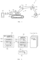
- Fig. 1 is a diagram illustrating a work support system 1 according to an embodiment of the present invention
- Fig. 2 is a block diagram of the work support system 1.
- the work support system 1 supports work of an operator operating a hydraulic shovel 2, which is a construction machine (movable body), by a function of machine guidance.
- a boom 4, an arm 5, and a bucket 6, which are movable portions are sequentially provided on a main body 3 which travels along an endless track.
- the work support system 1 is not limited to the hydraulic shovel 2, and can be widely applied to various work machines used for civil engineering, construction, and agricultural work, for example, such as a construction machine used for ground improvement.
- the boom 4, the arm 5, and the bucket 6 may be referred to as movable portions.
- the work support system 1 mainly includes detection devices 11a, 11b, and 11c, a main body device 12, a mobile information terminal device 13, and a notification unit 14.
- the detection devices 11a, 11b, and 11c are respectively provided in the boom 4, the arm 5, and the bucket 6 included in the hydraulic shovel 2, acquire information (for example, posture information of a movable portion) related to movement of a movable portion by a sensor unit to be described later, and transmit the information related to movement of the movable portion to the main body device 12 by data communication using a wireless communication unit to be described later.
- the posture information is information capable of detecting a posture of each movable portion, and in this embodiment, three-dimensional acceleration information and angular velocity information are applied.
- the detection devices 11a, 11b, and 11c are described. Note that, in the case of the present embodiment, since the detection device 11a, the detection device 11b, and the detection device 11c have the same configuration, hereinafter, a configuration of the detection device 11a is described, and description of the detection devices 11b and 11c is omitted.
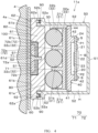
- the detection device 11a is provided on the boom 4, and, as illustrated in Figs. 3 and 4 , includes a substrate 20, a power supply means 30, a holding member 40, a case member 50, a cover member 60, a magnetic member 70, an attachment member 80, and an airtight member 90.
- the substrate 20 is a wiring substrate on which a predetermined wiring pattern is formed, and is disposed inside the case member 50.
- a sensor unit 21 and a control unit 22 are mounted on one surface P1 of the substrate 20 facing the bottom-portion side of the case member 50, which will be described later, and a wireless communication unit 23 to be connected to the control unit 22 is mounted on the other surface P2 of the substrate 20 which is opposite to the one surface P1.
- a six-axis inertial measurement unit (IMU) sensor in which a three-dimensional acceleration sensor and an angular velocity sensor are combined can be applied to the sensor unit 21, and the sensor unit 21 detects a three dimensional acceleration and an angular velocity.
- the sensor unit 21 is not limited to the above-described IMU sensor, and various configurations capable of detecting a posture of a movable portion, such as an acceleration sensor, an angular velocity sensor, and a geomagnetic sensor, can be widely applied.
- a measurement result by the sensor unit 21 is processed by the control unit 22 having a built-in arithmetic processing circuit, whereby posture information of the associated movable portion can be acquired.
- an antenna circuit pattern formed on the other surface P2 of the substrate 20 can be applied to the wireless communication unit 23, and the wireless communication unit 23 can transmit posture information of a movable portion processed by the control unit 22 to the main body device 12 by data communication using wireless communication.
- a communication unit having an antenna can be applied to the wireless communication unit 23, instead of the antenna circuit pattern.
- the power supply means 30 includes a battery 31 serving as a power source for supplying electric power to the substrate 20 (the sensor unit 21, the control unit 22, and the wireless communication unit 23), and a battery case 32 for accommodating the battery 31.
- a battery 31 serving as a power source for supplying electric power to the substrate 20 (the sensor unit 21, the control unit 22, and the wireless communication unit 23)
- a battery case 32 for accommodating the battery 31.
- the battery 31 three dry batteries 31a to 31c arranged side by side are used, and the substrate 20 is operated by electric power to be supplied from the battery 31, and transmits posture information of a movable portion processed by the control unit 22 to the main body device 12 by the wireless communication unit 23.
- the battery case 32 is formed of, for example, a resin material, and includes a base portion 32a formed in such a way as to be in parallel with the substrate 20, a peripheral wall 32b rising from a peripheral edge of the base portion 32a, and a partition wall 32c for partitioning between the dry cell 31a and the dry cell 31b, and between the dry cell 31b and the dry cell 31c. Focusing on a positional relationship between the substrate 20 and the power supply means 30, the substrate 20 and the power supply means 30 are disposed inside the case member 50 in such a way as to overlap each other.
- the holding member 40 is a substantially flat plate-shaped resin case (inner case) that holds the substrate 20 and the power supply means 30, and is disposed inside the case member 50 (a space portion to be described later) in such a way as to be interposed between the substrate 20 and the power supply means 30.
- the holding member 40 is provided with a flat plate portion 41 formed in such a way to be in parallel with the substrate 20, four protruding portions 42 protruding toward the substrate-20 side, and three positioning portions 43 (see Fig. 5 ) for positioning and fixing an outer peripheral portion 24 of the substrate 20.
- the flat plate portion 41 is joined to the battery case 32 by a double-sided tape 44.
- the battery case 32 power supply means 30
- the flat plate portion 41 holding member 40.
- the battery case 32 is located directly above the flat portion 41 (on the cover-member-60 side), when the battery 31 does not function (runs out), the battery 31 accommodated in the battery case 32 can be easily exchanged by removing the cover member 60 from the case member 50.
- the protruding portion 42 is formed with a screwing portion into which a screw S is screwed, and the substrate 20 is formed with a screw hole through which the screw S passes.
- the substrate 20 is fixed to the holding member 40 by fixing the screw S using the screw hole and the screwing portion. In other words, this means a configuration in which the substrate 20 is held by the protruding portion 42 (holding member 40).
- the positioning portion 43 is, for example, a positioning rib for positioning and fixing the outer peripheral portion 24 of the substrate 20 at three positions, and is provided, for example, at two positions along a longitudinal direction of the substrate 20 and at one position along a direction substantially orthogonal to the longitudinal direction in Fig. 5 .
- the positioning portion 43 is provided to suppress positional deviation of the substrate 20.
- the battery case 32 is joined to the flat plate portion 41, and the substrate 20 is fixed to the protruding portion 42 with the screws S, whereby the substrate 20 and the power supply means 30 are held on the front and rear surfaces of the holding member 40.
- the case member 50 is formed of, for example, a resin material, and accommodates, in a space portion H therein, the substrate 20 including the sensor unit 21, the wireless communication unit 23, and the like, the power supply means 30, the holding member 40, and a part of a main body portion of the cover member 60, which will be described later.
- the case member 50 includes a bottom portion 51 as a first wall portion to be formed in such a way as to face the substrate 20, a substantially frame-shaped side portion 52 as a second wall portion surrounding the substrate 20, the power supply means 30, and the holding member 40, and an opening portion 53 to be formed in such a way as to be associated with the bottom portion 51.
- the side portion 52 is formed into a substantially frame-shaped thick side portion 52a in which a portion located on the opening-portion-53 side has a thicker shape than other portions, and the thick side portion 52a (side portion 52) is formed with a recess portion 52b formed of a frame-shaped groove portion at a position associated with a mounted portion of the cover member 60, which will be described later.
- the reference sign 54 denotes six substantially semi-annular first bulging portions bulging outward of the thick side portion 52a (see Fig. 6 ), and the first bulging portion 54 has a hole 54a for passing a bolt T indicated by dotted lines in Fig. 7 , and is formed at four corners of the case member 50, namely, at each of the middle on the upper end side, and the middle on the lower end side in Fig. 6 .
- the cover member 60 is formed of, for example, a resin material, and is disposed on the thick side portion 52a (side portion 52) in such a way as to close the opening portion 53.
- the cover member 60 includes a main body portion 61 constituting main parts thereof, a mounted portion 62 formed around the main body portion 61, and placed on the thick side portion 52a (side portion 52), a pair of bulging portions 63 bulging in the left-right direction of the mounted portion 62 in such a way as not to overlap the case member 50, and six substantially semi-annular second bulging portions 64 bulging outward of the mounted portion 62 in such a way as to be associated with the first bulging portions 54.
- the main body portion 61 includes a flat surface 61a facing the battery-31 side, and an exposed surface 61b located on a side opposite to the flat surface 61a, the flat surface 61a is formed in such a way as to come into contact with the battery 31, and the exposed surface 61b is formed with a housing portion 61c at two positions, each of which has a substantially concave cross-sectional shape for accommodating the magnetic member 70.
- the reference sign 61d denotes a screw engagement portion formed from the housing portion 61c toward the battery-31 side, and the screw engagement portion 61d is used when the cover member 60 and the magnetic member 70 are fixed to each other by screws.
- the flat surface 61a and the battery 31 are in contact with each other.
- a clearance may be formed between the flat surface 61a and the battery 31, and a buffer member such as sponge may be interposed to fill the clearance.
- the mounted portion 62 is formed with a substantially frame-shaped projection portion 62a entering into the recess portion 52b.
- a positioning hole 63 a in which a positioning pin of the attachment member 80 to be described later is positioned is formed in the bulging portion 63 (see Fig. 8 ).
- the second bulging portion 64 has a hole 64a associated with the hole 54a as illustrated in Fig. 7 , and the cover member 60 is fastened and fixed to the case member 50 by fixing the bolt T into the holes 64a and 54a.
- the magnetic member 70 includes a magnet 71 and a yoke 72 that accommodates the magnet 71 therein, both of which are formed of a magnetic material.
- the magnet 71 is formed, for example, into a substantially annular shape, and includes a first exposed portion 71b located on the attachment-member-80 side, an associated portion 71a formed in such a way as to be associated with (face) the first exposed portion 71a, and a side surface portion 71c that connects the first exposed portion 71a and the associated portion 71b, as illustrated in Figs. 4 and 9 .
- the first exposed portion 71a is configured as an annular exposed surface
- the associated portion 71b is configured as an annular surface
- the side surface portion 71c is configured as a curved side surface.
- a hole 71d having a substantially inverted V-shape through which a fixing screw to be described later passes is formed in a central portion of the magnet 71.
- the magnet 71 may have a shape other than an
- the yoke 72 formed of an iron-based material is formed with a base portion 72a located on the associated-portion-71b side, and a surrounding portion 72b surrounding the side surface portion 71c, and a hole 72c communicating with the hole 71d is formed in a central portion of the base portion 72a.
- the first exposed portion 71a configured as an annular exposed surface is located on the substantially same plane as the exposed surface 61b of the main body portion 61, and the first exposed portion 71a and the exposed surface 61b are located at a position one step lower than a second exposed portion 72d of the yoke 72 located on the distal-end side (the attachment-member-80 side) of the surrounding portion 72b.
- the second exposed portion 72d is configured as an annular exposed surface.
- the magnetic member 70 configured as described above is fixed to the cover member 60 by an adhesive S1 and a fixing screw S2.
- the base portion 72a (magnetic member 70) and the main body portion 61 ( cover member 60) are joined by the adhesive S1 interposed between a surface portion X1 of the base portion 72a and an opposing surface X2 of the housing portion 61c facing thereto, and the magnetic member 70 and the main body portion 61 (cover member 60) are fixed by the fixing screw S2 that sequentially passes through the holes 71d and 72c, and is engaged with the screw engagement portion 61d.
- the attachment member 80 is a thin plate-like attachment plate formed of a magnetic material and capable of being coupled (fixed) to the second exposed portion 72d of the yoke 72 by a magnetic force.
- the attachment member 80 herein is coupled to the magnetic member 70 by the second exposed portion 72d, and a gap portion G is formed between the attachment member 80 and the first exposed portion 71a, and between the attachment member 80 and the exposed surface 61b.
- a pair of positioning pins 81 are formed to protrude toward the case-member-50 side at the middle on the left end side and at the middle on the right end side of the attachment member 80 in Fig. 6 (see Figs. 4 , 6 , and 8 ).
- the pair of positioning pins 81 are positioned and fixed to a pair of positioning holes 63a of the bulging portion 63, respectively, and are located on an imaginary line L that vertically divides the attachment member 80 (cover member 60) into two parts in Fig. 6 .
- the magnetic member 70 (housing portion 61c) is located on the imaginary line L, in addition to the positioning pins 81 (positioning holes 63a).
- a substantially frame-shaped (substantially quadrangular shape in cross section) rubber seal disposed in an empty space 91 to be formed between the projection portion 62a and the recess portion 52b can be applied to the airtight member 90.
- the air-tight member 90 is embedded in the recess portion 52b in a state of being compressed by the projection portion 62a. Providing the airtight member 90 in this manner enables to maintain the airtight state of the space portion H surrounded by the case member 50 and the cover member 60 in a favorable manner, and prevent foreign matter such as moisture or dust from entering into the space portion H.
- the detection device 11a is configured by the above-described components.
- a flat surface 82 of the attachment member 80 located on a side opposite to the positioning pin 81, and an outer surface 4a of the boom 4 facing the flat surface 82 are joined by a double-sided tape 100 as a joining means, whereby the detection device 11a is fixed to the boom 4 (see Fig. 4 ).
- the main body device 12 is provided in the main body 3 of the hydraulic shovel 2, transmits posture information by data communication using wireless communication by acquiring the posture information from the detection devices 11a, 11b, and 11c, and outputs support information to the notification unit 14 by receiving the support information by data communication using wireless communication.
- the main body device 12 includes a detection unit 12a, a microcomputer 12b, and a communication unit 12c that transmits and receives various pieces of data between the detection devices 1 1a, 11b, and 11c, and the mobile information terminal device 13 by data communication using wireless communication.
- the detection unit 12a is configured in the same manner as the detection devices 1 1a, 11b, and 11c, and acquires posture information of the main body 3.
- the microcomputer 12b controls an operation of each unit by executing a control program related to the main body device 12 by a built-in arithmetic processing circuit.
- the microcomputer 12b acquires posture information of the main body 3 by processing a measurement result to be output from the detection unit 12a in response to an instruction of the mobile information terminal device 13, and acquires posture information from the detection devices 1 1a, 11b, and 11c.
- the microcomputer 12b transmits these pieces of posture information to the mobile information terminal device 13 by data communication using wireless communication. Further, the microcomputer 12b receives support information to be transmitted from the mobile information terminal device 13, and outputs the support information to the notification unit 14. Note that, the support information herein means support information for supporting an operation of the operator. In addition, when it is practically sufficient, the detection unit 12a may be omitted as necessary.
- the mobile information terminal device 13 is a so-called smartphone or tablet terminal, and generates support information for supporting an operation of the operator, based on posture information by the detection devices 11a, 11b, and 11c to be acquired via the main body device 12, and posture information to be acquired by the detection unit 12a by executing application software related to the work support system 1.
- a difference (a movable amount to a work target) with respect to a work target in the hydraulic shovel 2 is assigned to the support information, whereby work can be performed easily and securely by the support information.
- the mobile information terminal device 13 includes a microcomputer 13a, a communication unit 13b, and a display unit 13c.
- the mobile information terminal device 13 acquires posture information from the main body device 12 by data communication using wireless communication with use of the communication unit 13b, and outputs support information for supporting an operation of the operator to the main body device 12. Further, the mobile information terminal device 13 acquires application software related to the work support system 1 from a server on a network.
- the mobile information terminal device 13 causes the microcomputer 13a to execute the application software acquired by the communication unit 13b, and detects a posture of the main body 3, based on posture information to be acquired in a reference posture (for example, a posture in which the bucket 6 is placed on the ground surface when work is started). Further, the mobile information terminal device 13 computes a current position of the bucket 6 by computing a change (movable amount) in the posture of each movable portion, based on a change in each piece of posture information from the reference posture.
- a reference posture for example, a posture in which the bucket 6 is placed on the ground surface when work is started.
- the microcomputer 13a successively computes a current position of the bucket 6, based on posture information to be sequentially input from the main body device 12 in such a way as to receive settings on a work target in advance, and computes a movable amount to the work target by computing a deviation (difference value) from the work target.
- the microcomputer 13a outputs the computed movable amount to the work target by the notification unit 14, as support information from the communication unit 13b via the main body device 12.
- the microcomputer 13a performs processing of successively displaying a computation result of a movable amount to a work target on the display unit 13c constituted of a display medium such as, for example, a liquid crystal display panel. Note that, in this case, display equivalent to a display content of the display unit 13c may be performed on the notification unit 14.
- the notification unit 14 notifies the operator of support information for supporting an operation of the operator to be input from the main body device 12 at an operator's seat of the hydraulic shovel 2.
- the notification unit 14 displays, for example, a movable amount to a work target by segment display using light emitting diodes.
- the notification unit 14 may be constituted of an image display panel or the like.
- various methods such as a case where notification is performed by display of a numerical value, a case where notification is performed by display of a meter, and the like can be applied.
- notification may be performed by an audio sound or an alarm sound, instead of segment display or display by an image display panel.
- the notification unit 14 may be directly driven by the mobile information terminal device 13.
- the present embodiment includes the sensor unit 21 that acquires information (posture information) related to movement of a movable portion provided in the hydraulic shovel 2, and transmits the acquired information (posture information) related to movement by data communication using the wireless communication unit 23, the power supply means 30 that supplies electric power to the sensor unit 21, and the case member 50 that accommodates the wireless communication unit 23, the sensor unit 21, and the power supply means 30.
- posture information is acquired by the sensor unit 21 by power supply from the power supply means 30 provided in the space portion H of the case member 50, it is not necessary to install a power supply cable along a movable portion as in the conventional art. Therefore, according to the configuration of the present invention, it is possible to provide a compact detection device in which a wiring operation using a power supply cable is eliminated, and the power supply cable is not necessary. Further, in this case, since the wireless communication unit 23 is formed on the substrate 20 provided in the space portion H, it is not necessary to wire and connect a cable for data communication to the main body device 12. Therefore, it is possible to provide a more compact detection device which does not require any cables.
- the substrate 20 and the power supply means 30 are disposed in such a way as to overlap each other inside the case member 50, which is the space portion H.
- the substrate 20 and the power supply means 30 are disposed in such a way as to overlap each other inside the case member 50, which is the space portion H.
- the three positioning portions 43 for positioning and fixing the outer peripheral portion 24 of the substrate 20 are formed on the holding member 40, it is possible to fix the substrate 20 and the holding member 40 by the screws S in a state that the outer peripheral portion 24 is temporarily fixed by the positioning portions 43, which is advantageous in improving assembling workability.
- three positioning portions 43 for positioning and fixing the outer peripheral portion (side surface portion) 24 of the substrate 20 are formed on the holding member 40, but the number of the positioning portions 43 may be one or two.
- the cross-sectional shape of the airtight member 90 disposed in the empty space 91 is a quadrangular shape
- the airtight member 90 may have any shape as long as the airtight state of the space portion H is favorably maintained.
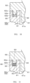
- a convex portion 62b may be further formed on the projection portion 62a, and a concave portion 92 which is fitted to the convex portion 62b in a concave-convex manner may be formed in the airtight member 90, or as illustrated in Fig.
- the airtight member 90 in which four grooves 93 in total, specifically, two grooves 93 on the upper side and two grooves 93 on the lower side are formed may be applied.
- a configuration in which the concave-convex relationship is reversed specifically, a configuration in which a concave portion is formed in the projection portion 62a, and a convex portion capable of fitting to the concave portion formed in the projection portion 62a in a concave-convex manner is formed on the airtight member 90 may be adopted.
- the concave portion 92 is formed on the upper side of the airtight member 90, but a concave portion may be formed on the upper and lower sides of the airtight member 90.
- the recess portion 52b is formed in the thick side portion 52a (side portion 52), the projection portion 62a entering into the recess portion 52b is formed on the mounted portion 62, and the airtight member 90 is disposed in the empty space 91 to be formed between the recess portion 52b and the projection portion 62a.
- a recess portion may be formed in the mounted portion 62, a projection portion entering into the recess portion may be formed on the thick side portion 52a (side portion 52), and the airtight member 90 may be disposed in an empty space to be formed between the recess portion and the projection portion.
Landscapes
- Engineering & Computer Science (AREA)
- Computer Networks & Wireless Communication (AREA)
- Signal Processing (AREA)
- Chemical & Material Sciences (AREA)
- Chemical Kinetics & Catalysis (AREA)
- Electrochemistry (AREA)
- General Chemical & Material Sciences (AREA)
- Component Parts Of Construction Machinery (AREA)
- Arrangements For Transmission Of Measured Signals (AREA)
- Measurement Of Length, Angles, Or The Like Using Electric Or Magnetic Means (AREA)
Abstract
Description
- The present invention relates to a detection device disposed in a movable portion such as a boom, an arm, or a bucket provided in a work machine, for example.
- Conventionally, as this type of detection device, for example, a detection device described in the following Patent Document 1 is known. The detection device as an inertial sensor described in Patent Document 1 detects a posture of a movable portion such as a boom, an arm, or a bucket provided in a construction machine (work machine), and is provided in the vicinity of a rotation shaft of the movable portion in such a way that a dynamic acceleration at a time of operation of the movable portion is unlikely to act.
- Patent Document 1:
Japanese Unexamined Patent Application Publication No. 2019-132038 - A detection device disposed in the above-described movable portion (a boom, an arm, or a bucket) is operated by being supplied with electric power from a power supply device mounted on, for example, a main body (such as a swing structure) of a construction machine via a power supply cable. For example, it is conceived that a power supply cable is installed along a movable portion in view of a structure of a construction machine. However, in such a configuration, since a power supply cable is required to operate the detection device, a large-scale wiring operation using the power supply cable is required, and a compact configuration of a detection device that does not require the wiring operation is desired.
- The present invention has been made in view of the above-described circumstances, and an object of the present invention is to provide a detection device that can be made compact.
- A detection device according to a first aspect includes: a sensor unit that acquires information related to movement of a movable portion provided in a movable body, and transmits the acquired information related to movement by data communication using a wireless communication unit; a power supply means that supplies electric power to the sensor unit; and a case member that accommodates the wireless communication unit, the sensor unit, and the power supply means.
- A detection device according to a second aspect is that, in the detection device according to the first aspect, the sensor unit is mounted on a substrate disposed inside the case member.
- A detection device according to a third aspect is that, in the detection device according to the second aspect, the case member includes a first wall portion facing the substrate, a second wall portion surrounding the power supply means, and an opening portion associated with the first wall portion, and a cover member is disposed on the second wall portion in such a way as to close the opening portion.
- A detection device according to a fourth aspect is that, in the detection device according to any one of the first to the third aspects, the power supply means includes a battery serving as a power source for supplying the electric power, and a battery case that accommodates the battery.
- A detection device according to a fifth aspect is that, in the detection device according to any one of the second to the fourth aspects, the substrate and the power supply means are disposed inside the case member in such a way as to overlap each other.
- A detection device according to a sixth aspect further includes, in the detection device according to any one of the second to the fifth aspects, a holding member interposed between the substrate and the power supply means, wherein the substrate and the power supply means are held by the holding member.
- A detection device according to a seventh aspect is that, in the detection device according to the sixth aspect, the holding member is formed with a positioning portion for positioning and fixing an outer peripheral portion of the substrate.
- A detection device according to an eighth aspect is that, in the detection device according to any one of the third to the seventh aspects, the cover member includes a mounted portion to be placed on the second wall portion, and one of the second wall portion and the mounted portion is formed with a recess portion, the other thereof is formed with a projection portion entering into the recess portion, and an airtight member is disposed in an empty space to be formed between the recess portion and the projection portion.
- According to the present invention, it is possible to provide a detection device that can be made compact.
-
-
Fig. 1 is a diagram illustrating a work support system according to an embodiment of the present invention. -
Fig. 2 is a block diagram of the work support system according to the embodiment. -
Fig. 3 is a front view of a detection device according to the embodiment. -
Fig. 4 is a cross-sectional view taken along the line A-A inFig. 3 . -
Fig. 5 is a diagram illustrating a substrate and a support portion when viewed from the direction of the arrow B inFig. 4 . -
Fig. 6 is a rear view of the detection device when an attachment member is viewed from the case-member side inFig. 4 . -
Fig. 7 is a cross-sectional view taken along the line B-B inFig. 3 . -
Fig. 8 is a cross-sectional view taken along the line C-C inFig. 3 . -
Fig. 9 is an enlarged cross-sectional view of main parts illustrating a cover member, a magnetic member, and the attachment member according to the embodiment. -
Fig. 10 is an enlarged cross-sectional view of main parts of a detection device according to a modification of the embodiment. -
Fig. 11 is an enlarged cross-sectional view of main parts of a detection device according to another modification of the embodiment. - In the following, an embodiment in which a detection device according to the present invention is applied to a work support system is described with reference to
Figs. 1 to 9 . -
Fig. 1 is a diagram illustrating a work support system 1 according to an embodiment of the present invention, andFig. 2 is a block diagram of the work support system 1. - The work support system 1 supports work of an operator operating a
hydraulic shovel 2, which is a construction machine (movable body), by a function of machine guidance. Herein, in thehydraulic shovel 2, aboom 4, anarm 5, and abucket 6, which are movable portions, are sequentially provided on amain body 3 which travels along an endless track. Note that, the work support system 1 is not limited to thehydraulic shovel 2, and can be widely applied to various work machines used for civil engineering, construction, and agricultural work, for example, such as a construction machine used for ground improvement. Further, in the following description, theboom 4, thearm 5, and thebucket 6 may be referred to as movable portions. - As illustrated in
Fig. 2 , the work support system 1 mainly includesdetection devices main body device 12, a mobileinformation terminal device 13, and anotification unit 14. Herein, thedetection devices boom 4, thearm 5, and thebucket 6 included in thehydraulic shovel 2, acquire information (for example, posture information of a movable portion) related to movement of a movable portion by a sensor unit to be described later, and transmit the information related to movement of the movable portion to themain body device 12 by data communication using a wireless communication unit to be described later. Herein, the posture information is information capable of detecting a posture of each movable portion, and in this embodiment, three-dimensional acceleration information and angular velocity information are applied. - Next, the
detection devices detection device 11a, thedetection device 11b, and thedetection device 11c have the same configuration, hereinafter, a configuration of thedetection device 11a is described, and description of thedetection devices - The
detection device 11a is provided on theboom 4, and, as illustrated inFigs. 3 and4 , includes asubstrate 20, a power supply means 30, aholding member 40, acase member 50, acover member 60, amagnetic member 70, anattachment member 80, and anairtight member 90. - The
substrate 20 is a wiring substrate on which a predetermined wiring pattern is formed, and is disposed inside thecase member 50. In addition, in this case, asensor unit 21 and acontrol unit 22 are mounted on one surface P1 of thesubstrate 20 facing the bottom-portion side of thecase member 50, which will be described later, and awireless communication unit 23 to be connected to thecontrol unit 22 is mounted on the other surface P2 of thesubstrate 20 which is opposite to the one surface P1. - For example, a six-axis inertial measurement unit (IMU) sensor in which a three-dimensional acceleration sensor and an angular velocity sensor are combined can be applied to the
sensor unit 21, and thesensor unit 21 detects a three dimensional acceleration and an angular velocity. Note that, thesensor unit 21 is not limited to the above-described IMU sensor, and various configurations capable of detecting a posture of a movable portion, such as an acceleration sensor, an angular velocity sensor, and a geomagnetic sensor, can be widely applied. Further, a measurement result by thesensor unit 21 is processed by thecontrol unit 22 having a built-in arithmetic processing circuit, whereby posture information of the associated movable portion can be acquired. - For example, an antenna circuit pattern formed on the other surface P2 of the
substrate 20 can be applied to thewireless communication unit 23, and thewireless communication unit 23 can transmit posture information of a movable portion processed by thecontrol unit 22 to themain body device 12 by data communication using wireless communication. Note that, a communication unit having an antenna can be applied to thewireless communication unit 23, instead of the antenna circuit pattern. - The power supply means 30 includes a
battery 31 serving as a power source for supplying electric power to the substrate 20 (thesensor unit 21, thecontrol unit 22, and the wireless communication unit 23), and abattery case 32 for accommodating thebattery 31. As thebattery 31, threedry batteries 31a to 31c arranged side by side are used, and thesubstrate 20 is operated by electric power to be supplied from thebattery 31, and transmits posture information of a movable portion processed by thecontrol unit 22 to themain body device 12 by thewireless communication unit 23. - The
battery case 32 is formed of, for example, a resin material, and includes abase portion 32a formed in such a way as to be in parallel with thesubstrate 20, aperipheral wall 32b rising from a peripheral edge of thebase portion 32a, and apartition wall 32c for partitioning between thedry cell 31a and thedry cell 31b, and between thedry cell 31b and thedry cell 31c. Focusing on a positional relationship between thesubstrate 20 and the power supply means 30, thesubstrate 20 and the power supply means 30 are disposed inside thecase member 50 in such a way as to overlap each other. - The
holding member 40 is a substantially flat plate-shaped resin case (inner case) that holds thesubstrate 20 and the power supply means 30, and is disposed inside the case member 50 (a space portion to be described later) in such a way as to be interposed between thesubstrate 20 and the power supply means 30. Theholding member 40 is provided with aflat plate portion 41 formed in such a way to be in parallel with thesubstrate 20, fourprotruding portions 42 protruding toward the substrate-20 side, and three positioning portions 43 (seeFig. 5 ) for positioning and fixing an outerperipheral portion 24 of thesubstrate 20. - The
flat plate portion 41 is joined to thebattery case 32 by a double-sided tape 44. Thus, the battery case 32 (power supply means 30) is held by the flat plate portion 41 (holding member 40). In addition, since thebattery case 32 is located directly above the flat portion 41 (on the cover-member-60 side), when thebattery 31 does not function (runs out), thebattery 31 accommodated in thebattery case 32 can be easily exchanged by removing thecover member 60 from thecase member 50. - Although not illustrated in detail herein, the
protruding portion 42 is formed with a screwing portion into which a screw S is screwed, and thesubstrate 20 is formed with a screw hole through which the screw S passes. Thesubstrate 20 is fixed to the holdingmember 40 by fixing the screw S using the screw hole and the screwing portion. In other words, this means a configuration in which thesubstrate 20 is held by the protruding portion 42 (holding member 40). - The positioning
portion 43 is, for example, a positioning rib for positioning and fixing the outerperipheral portion 24 of thesubstrate 20 at three positions, and is provided, for example, at two positions along a longitudinal direction of thesubstrate 20 and at one position along a direction substantially orthogonal to the longitudinal direction inFig. 5 . At a time of screw fixing work of thesubstrate 20 and the holdingmember 40 using the screws S, the positioningportion 43 is provided to suppress positional deviation of thesubstrate 20. Further, in the present example, thebattery case 32 is joined to theflat plate portion 41, and thesubstrate 20 is fixed to the protrudingportion 42 with the screws S, whereby thesubstrate 20 and the power supply means 30 are held on the front and rear surfaces of the holdingmember 40. - The
case member 50 is formed of, for example, a resin material, and accommodates, in a space portion H therein, thesubstrate 20 including thesensor unit 21, thewireless communication unit 23, and the like, the power supply means 30, the holdingmember 40, and a part of a main body portion of thecover member 60, which will be described later. Thecase member 50 includes abottom portion 51 as a first wall portion to be formed in such a way as to face thesubstrate 20, a substantially frame-shapedside portion 52 as a second wall portion surrounding thesubstrate 20, the power supply means 30, and the holdingmember 40, and anopening portion 53 to be formed in such a way as to be associated with thebottom portion 51. - The
side portion 52 is formed into a substantially frame-shapedthick side portion 52a in which a portion located on the opening-portion-53 side has a thicker shape than other portions, and thethick side portion 52a (side portion 52) is formed with arecess portion 52b formed of a frame-shaped groove portion at a position associated with a mounted portion of thecover member 60, which will be described later. Note that, thereference sign 54 denotes six substantially semi-annular first bulging portions bulging outward of thethick side portion 52a (seeFig. 6 ), and the first bulgingportion 54 has ahole 54a for passing a bolt T indicated by dotted lines inFig. 7 , and is formed at four corners of thecase member 50, namely, at each of the middle on the upper end side, and the middle on the lower end side inFig. 6 . - The
cover member 60 is formed of, for example, a resin material, and is disposed on thethick side portion 52a (side portion 52) in such a way as to close the openingportion 53. As illustrated inFigs. 3 to 7 , thecover member 60 includes amain body portion 61 constituting main parts thereof, a mountedportion 62 formed around themain body portion 61, and placed on thethick side portion 52a (side portion 52), a pair of bulgingportions 63 bulging in the left-right direction of the mountedportion 62 in such a way as not to overlap thecase member 50, and six substantially semi-annular second bulgingportions 64 bulging outward of the mountedportion 62 in such a way as to be associated with the first bulgingportions 54. - The
main body portion 61 includes aflat surface 61a facing the battery-31 side, and an exposedsurface 61b located on a side opposite to theflat surface 61a, theflat surface 61a is formed in such a way as to come into contact with thebattery 31, and the exposedsurface 61b is formed with ahousing portion 61c at two positions, each of which has a substantially concave cross-sectional shape for accommodating themagnetic member 70. In addition, thereference sign 61d denotes a screw engagement portion formed from thehousing portion 61c toward the battery-31 side, and thescrew engagement portion 61d is used when thecover member 60 and themagnetic member 70 are fixed to each other by screws. - Note that, in the case of the present embodiment, the
flat surface 61a and thebattery 31 are in contact with each other. However, for example, a clearance may be formed between theflat surface 61a and thebattery 31, and a buffer member such as sponge may be interposed to fill the clearance. - The mounted
portion 62 is formed with a substantially frame-shapedprojection portion 62a entering into therecess portion 52b. Apositioning hole 63 a in which a positioning pin of theattachment member 80 to be described later is positioned is formed in the bulging portion 63 (seeFig. 8 ). The second bulgingportion 64 has ahole 64a associated with thehole 54a as illustrated inFig. 7 , and thecover member 60 is fastened and fixed to thecase member 50 by fixing the bolt T into theholes - The
magnetic member 70 includes amagnet 71 and ayoke 72 that accommodates themagnet 71 therein, both of which are formed of a magnetic material. Themagnet 71 is formed, for example, into a substantially annular shape, and includes a first exposedportion 71b located on the attachment-member-80 side, an associatedportion 71a formed in such a way as to be associated with (face) the first exposedportion 71a, and aside surface portion 71c that connects the first exposedportion 71a and the associatedportion 71b, as illustrated inFigs. 4 and9 . The first exposedportion 71a is configured as an annular exposed surface, the associatedportion 71b is configured as an annular surface, and theside surface portion 71c is configured as a curved side surface. In addition, ahole 71d having a substantially inverted V-shape through which a fixing screw to be described later passes is formed in a central portion of themagnet 71. Note that, themagnet 71 may have a shape other than an annular shape. - Meanwhile, the
yoke 72 formed of an iron-based material is formed with abase portion 72a located on the associated-portion-71b side, and a surroundingportion 72b surrounding theside surface portion 71c, and ahole 72c communicating with thehole 71d is formed in a central portion of thebase portion 72a. Further, in this case, the first exposedportion 71a configured as an annular exposed surface is located on the substantially same plane as the exposedsurface 61b of themain body portion 61, and the first exposedportion 71a and the exposedsurface 61b are located at a position one step lower than a second exposed portion 72d of theyoke 72 located on the distal-end side (the attachment-member-80 side) of the surroundingportion 72b. The second exposed portion 72d is configured as an annular exposed surface. - The
magnetic member 70 configured as described above is fixed to thecover member 60 by an adhesive S1 and a fixing screw S2. Specifically, in this case, thebase portion 72a (magnetic member 70) and the main body portion 61 ( cover member 60) are joined by the adhesive S1 interposed between a surface portion X1 of thebase portion 72a and an opposing surface X2 of thehousing portion 61c facing thereto, and themagnetic member 70 and the main body portion 61 (cover member 60) are fixed by the fixing screw S2 that sequentially passes through theholes screw engagement portion 61d. - The
attachment member 80 is a thin plate-like attachment plate formed of a magnetic material and capable of being coupled (fixed) to the second exposed portion 72d of theyoke 72 by a magnetic force. In other words, theattachment member 80 herein is coupled to themagnetic member 70 by the second exposed portion 72d, and a gap portion G is formed between theattachment member 80 and the first exposedportion 71a, and between theattachment member 80 and the exposedsurface 61b. - Further, in the
attachment member 80 provided in such a way as to be interposed between a movable portion (boom 4) and thecover 60, a pair of positioning pins 81 are formed to protrude toward the case-member-50 side at the middle on the left end side and at the middle on the right end side of theattachment member 80 inFig. 6 (seeFigs. 4 ,6 , and8 ). In this case, the pair of positioning pins 81 are positioned and fixed to a pair ofpositioning holes 63a of the bulgingportion 63, respectively, and are located on an imaginary line L that vertically divides the attachment member 80 (cover member 60) into two parts inFig. 6 . Note that, the magnetic member 70 (housing portion 61c) is located on the imaginary line L, in addition to the positioning pins 81 (positioning holes 63a). - As illustrated in
Fig. 7 , a substantially frame-shaped (substantially quadrangular shape in cross section) rubber seal disposed in anempty space 91 to be formed between theprojection portion 62a and therecess portion 52b can be applied to theairtight member 90. Specifically, in this case, the air-tight member 90 is embedded in therecess portion 52b in a state of being compressed by theprojection portion 62a. Providing theairtight member 90 in this manner enables to maintain the airtight state of the space portion H surrounded by thecase member 50 and thecover member 60 in a favorable manner, and prevent foreign matter such as moisture or dust from entering into the space portion H. Thedetection device 11a is configured by the above-described components. Then, aflat surface 82 of theattachment member 80 located on a side opposite to thepositioning pin 81, and anouter surface 4a of theboom 4 facing theflat surface 82 are joined by a double-sided tape 100 as a joining means, whereby thedetection device 11a is fixed to the boom 4 (seeFig. 4 ). - The
main body device 12 is provided in themain body 3 of thehydraulic shovel 2, transmits posture information by data communication using wireless communication by acquiring the posture information from thedetection devices notification unit 14 by receiving the support information by data communication using wireless communication. For this reason, as illustrated inFig. 2 , themain body device 12 includes adetection unit 12a, amicrocomputer 12b, and acommunication unit 12c that transmits and receives various pieces of data between the detection devices 1 1a, 11b, and 11c, and the mobileinformation terminal device 13 by data communication using wireless communication. - The
detection unit 12a is configured in the same manner as the detection devices 1 1a, 11b, and 11c, and acquires posture information of themain body 3. Themicrocomputer 12b controls an operation of each unit by executing a control program related to themain body device 12 by a built-in arithmetic processing circuit. Thus, themicrocomputer 12b acquires posture information of themain body 3 by processing a measurement result to be output from thedetection unit 12a in response to an instruction of the mobileinformation terminal device 13, and acquires posture information from the detection devices 1 1a, 11b, and 11c. - Further, the
microcomputer 12b transmits these pieces of posture information to the mobileinformation terminal device 13 by data communication using wireless communication. Further, themicrocomputer 12b receives support information to be transmitted from the mobileinformation terminal device 13, and outputs the support information to thenotification unit 14. Note that, the support information herein means support information for supporting an operation of the operator. In addition, when it is practically sufficient, thedetection unit 12a may be omitted as necessary. - The mobile
information terminal device 13 is a so-called smartphone or tablet terminal, and generates support information for supporting an operation of the operator, based on posture information by thedetection devices main body device 12, and posture information to be acquired by thedetection unit 12a by executing application software related to the work support system 1. In this embodiment, a difference (a movable amount to a work target) with respect to a work target in thehydraulic shovel 2 is assigned to the support information, whereby work can be performed easily and securely by the support information. - The mobile
information terminal device 13 includes amicrocomputer 13a, acommunication unit 13b, and adisplay unit 13c. The mobileinformation terminal device 13 acquires posture information from themain body device 12 by data communication using wireless communication with use of thecommunication unit 13b, and outputs support information for supporting an operation of the operator to themain body device 12. Further, the mobileinformation terminal device 13 acquires application software related to the work support system 1 from a server on a network. - The mobile
information terminal device 13 causes themicrocomputer 13a to execute the application software acquired by thecommunication unit 13b, and detects a posture of themain body 3, based on posture information to be acquired in a reference posture (for example, a posture in which thebucket 6 is placed on the ground surface when work is started). Further, the mobileinformation terminal device 13 computes a current position of thebucket 6 by computing a change (movable amount) in the posture of each movable portion, based on a change in each piece of posture information from the reference posture. - The
microcomputer 13a successively computes a current position of thebucket 6, based on posture information to be sequentially input from themain body device 12 in such a way as to receive settings on a work target in advance, and computes a movable amount to the work target by computing a deviation (difference value) from the work target. In addition, themicrocomputer 13a outputs the computed movable amount to the work target by thenotification unit 14, as support information from thecommunication unit 13b via themain body device 12. - In addition, the
microcomputer 13a performs processing of successively displaying a computation result of a movable amount to a work target on thedisplay unit 13c constituted of a display medium such as, for example, a liquid crystal display panel. Note that, in this case, display equivalent to a display content of thedisplay unit 13c may be performed on thenotification unit 14. - The
notification unit 14 notifies the operator of support information for supporting an operation of the operator to be input from themain body device 12 at an operator's seat of thehydraulic shovel 2. In this embodiment, thenotification unit 14 displays, for example, a movable amount to a work target by segment display using light emitting diodes. - Note that, the
notification unit 14 may be constituted of an image display panel or the like. In addition, in notification using an image display panel or the like as described above, various methods such as a case where notification is performed by display of a numerical value, a case where notification is performed by display of a meter, and the like can be applied. Further, notification may be performed by an audio sound or an alarm sound, instead of segment display or display by an image display panel. Alternatively, thenotification unit 14 may be directly driven by the mobileinformation terminal device 13. - As described above, the present embodiment includes the
sensor unit 21 that acquires information (posture information) related to movement of a movable portion provided in thehydraulic shovel 2, and transmits the acquired information (posture information) related to movement by data communication using thewireless communication unit 23, the power supply means 30 that supplies electric power to thesensor unit 21, and thecase member 50 that accommodates thewireless communication unit 23, thesensor unit 21, and the power supply means 30. - Since posture information is acquired by the
sensor unit 21 by power supply from the power supply means 30 provided in the space portion H of thecase member 50, it is not necessary to install a power supply cable along a movable portion as in the conventional art. Therefore, according to the configuration of the present invention, it is possible to provide a compact detection device in which a wiring operation using a power supply cable is eliminated, and the power supply cable is not necessary. Further, in this case, since thewireless communication unit 23 is formed on thesubstrate 20 provided in the space portion H, it is not necessary to wire and connect a cable for data communication to themain body device 12. Therefore, it is possible to provide a more compact detection device which does not require any cables. - In addition, in the present embodiment, the
substrate 20 and the power supply means 30 are disposed in such a way as to overlap each other inside thecase member 50, which is the space portion H. Thus, an increase in the size of the shape of theside portion 52 of thecase member 50 is suppressed, and it is possible to provide a compact detection device. - Further, in the present embodiment, since the three
positioning portions 43 for positioning and fixing the outerperipheral portion 24 of thesubstrate 20 are formed on the holdingmember 40, it is possible to fix thesubstrate 20 and the holdingmember 40 by the screws S in a state that the outerperipheral portion 24 is temporarily fixed by thepositioning portions 43, which is advantageous in improving assembling workability. - Note that, the present invention is not limited to the above embodiment and the drawings. Modifications (including deletion of constituent elements) may be appropriately added to the embodiment and the drawings as long as the gist of the present invention is not changed.
- For example, in the above embodiment, three
positioning portions 43 for positioning and fixing the outer peripheral portion (side surface portion) 24 of thesubstrate 20 are formed on the holdingmember 40, but the number of thepositioning portions 43 may be one or two. - Further, in the above embodiment, although the cross-sectional shape of the
airtight member 90 disposed in theempty space 91 is a quadrangular shape, theairtight member 90 may have any shape as long as the airtight state of the space portion H is favorably maintained. For example, as illustrated inFig. 10 , aconvex portion 62b may be further formed on theprojection portion 62a, and aconcave portion 92 which is fitted to theconvex portion 62b in a concave-convex manner may be formed in theairtight member 90, or as illustrated inFig. 11 , theairtight member 90 in which fourgrooves 93 in total, specifically, twogrooves 93 on the upper side and twogrooves 93 on the lower side are formed may be applied. Note that, inFig. 10 , a configuration in which the concave-convex relationship is reversed, specifically, a configuration in which a concave portion is formed in theprojection portion 62a, and a convex portion capable of fitting to the concave portion formed in theprojection portion 62a in a concave-convex manner is formed on theairtight member 90 may be adopted. Further, inFig. 10 , theconcave portion 92 is formed on the upper side of theairtight member 90, but a concave portion may be formed on the upper and lower sides of theairtight member 90. - Further, in the above embodiment, the
recess portion 52b is formed in thethick side portion 52a (side portion 52), theprojection portion 62a entering into therecess portion 52b is formed on the mountedportion 62, and theairtight member 90 is disposed in theempty space 91 to be formed between therecess portion 52b and theprojection portion 62a. However, conversely, a recess portion may be formed in the mountedportion 62, a projection portion entering into the recess portion may be formed on thethick side portion 52a (side portion 52), and theairtight member 90 may be disposed in an empty space to be formed between the recess portion and the projection portion. -
- 1 Work support system
- 2 Hydraulic shovel (movable body)
- 3 Main body
- 4 Boom (movable portion)
- 5 Arm (movable portion)
- 6 Bucket (movable portion)
- 11a, 11b, 11c Detection device
- 12 Main body device
- 13 Mobile information terminal device
- 14 Notification unit
- 20 Substrate
- 21 Sensor unit
- 23 Wireless communication unit
- 30 Power supply means
- 31 Battery
- 32 Battery case
- 40 Holding member
- 41 Flat plate portion
- 42 Protruding portion
- 43 Positioning portion
- 50 Case member
- 51 Bottom portion (first wall portion)
- 52 Side portion (second wall portion)
- 52a Thick side portion
- 53 Opening portion
- 60 Cover member
- 61 Main body portion
- 61c Housing portion
- 62 Mounted portion
- 70 Magnetic member
- 71 Magnet
- 72 Yoke
- 80 Attachment member
- 90 Airtight member
Claims (8)
- A detection device comprising:a sensor unit that acquires information related to movement of a movable portion provided in a movable body, and transmits the acquired information related to movement by data communication using a wireless communication unit;power supply means that supplies electric power to the sensor unit; anda case member that accommodates the wireless communication unit, the sensor unit, and the power supply means.
- The detection device according to claim 1, wherein
the sensor unit is mounted on a substrate disposed inside the case member. - The detection device according to claim 2, whereinthe case member includes a first wall portion facing the substrate, a second wall portion surrounding the power supply means, and an opening portion associated with the first wall portion, anda cover member is disposed on the second wall portion in such a way as to close the opening portion.
- The detection device according to claim 1, wherein
the power supply means includes a battery serving as a power source for supplying the electric power, and a battery case that accommodates the battery. - The detection device according to any one of claims 2 to 4, wherein
the substrate and the power supply means are disposed inside the case member in such a way as to overlap each other. - The detection device according to claim 5, further comprisinga holding member interposed between the substrate and the power supply means, whereinthe substrate and the power supply means are held by the holding member.
- The detection device according to claim 6, wherein
the holding member is formed with a positioning portion for positioning and fixing an outer peripheral portion of the substrate. - The detection device according to claim 3, whereinthe cover member includes a mounted portion to be placed on the second wall portion, andone of the second wall portion and the mounted portion is formed with a recess portion, the other thereof is formed with a projection portion entering into the recess portion, and an airtight member is disposed in an empty space to be formed between the recess portion and the projection portion.
Applications Claiming Priority (2)
| Application Number | Priority Date | Filing Date | Title |
|---|---|---|---|
| JP2021122256 | 2021-07-27 | ||
| PCT/JP2022/028730 WO2023008412A1 (en) | 2021-07-27 | 2022-07-26 | Detection device |
Publications (2)
| Publication Number | Publication Date |
|---|---|
| EP4379153A1 true EP4379153A1 (en) | 2024-06-05 |
| EP4379153A4 EP4379153A4 (en) | 2025-07-16 |
Family
ID=85087655
Family Applications (1)
| Application Number | Title | Priority Date | Filing Date |
|---|---|---|---|
| EP22849473.8A Pending EP4379153A4 (en) | 2021-07-27 | 2022-07-26 | DETECTION DEVICE |
Country Status (6)
| Country | Link |
|---|---|
| US (1) | US20240322850A1 (en) |
| EP (1) | EP4379153A4 (en) |
| JP (1) | JPWO2023008412A1 (en) |
| CN (1) | CN117813432A (en) |
| CA (1) | CA3227693A1 (en) |
| WO (1) | WO2023008412A1 (en) |
Family Cites Families (5)
| Publication number | Priority date | Publication date | Assignee | Title |
|---|---|---|---|---|
| FR2915279B1 (en) * | 2007-04-20 | 2009-10-02 | Agatec Soc Par Actions Simplif | AUTONOMOUS POSITION SENSOR AND POSITION DETERMINATION SYSTEM OF WORK MACHINE TOOL VIA POSITION SENSORS. |
| JP6636806B2 (en) * | 2016-01-08 | 2020-01-29 | 株式会社アコーズ | Animal behavior analyzer |
| JP7396784B2 (en) | 2018-01-31 | 2023-12-12 | 住友重機械工業株式会社 | excavator |
| JP2019200123A (en) * | 2018-05-16 | 2019-11-21 | セイコーエプソン株式会社 | Sensor unit, construction machine, and structure monitoring device |
| JP7218512B2 (en) * | 2018-07-30 | 2023-02-07 | セイコーエプソン株式会社 | Sensor modules, electronic devices and mobile objects |
-
2022
- 2022-07-26 JP JP2023538540A patent/JPWO2023008412A1/ja active Pending
- 2022-07-26 EP EP22849473.8A patent/EP4379153A4/en active Pending
- 2022-07-26 CA CA3227693A patent/CA3227693A1/en active Pending
- 2022-07-26 US US18/580,590 patent/US20240322850A1/en active Pending
- 2022-07-26 WO PCT/JP2022/028730 patent/WO2023008412A1/en not_active Ceased
- 2022-07-26 CN CN202280051968.XA patent/CN117813432A/en active Pending
Also Published As
| Publication number | Publication date |
|---|---|
| EP4379153A4 (en) | 2025-07-16 |
| CA3227693A1 (en) | 2023-02-02 |
| CN117813432A (en) | 2024-04-02 |
| WO2023008412A1 (en) | 2023-02-02 |
| US20240322850A1 (en) | 2024-09-26 |
| JPWO2023008412A1 (en) | 2023-02-02 |
Similar Documents
| Publication | Publication Date | Title |
|---|---|---|
| US11441927B2 (en) | Sensor unit, construction machine, and structure monitoring device | |
| US10908692B2 (en) | Touchpad module | |
| WO2020122387A1 (en) | Electronic device including acoustic module | |
| US20210078160A1 (en) | Mounting mechanism and robot | |
| US20220171150A1 (en) | Lens driving device | |
| KR20150108401A (en) | Construction machinery display device and construction machinery | |
| US20240322850A1 (en) | Detection device | |
| KR20200116693A (en) | Method for controlling display and electronic deivce thereof | |
| CN112577486A (en) | Inertial measurement unit | |
| EP3928178A1 (en) | Electronic device including battery | |
| WO2021251463A1 (en) | Work assist system and work assist method | |
| JP6685259B2 (en) | Rolling control equipment for rolling machines | |
| JP2023030234A (en) | detector | |
| JP2016134548A (en) | Electronic apparatus | |
| JP7746739B2 (en) | Detection Device | |
| CN111216111A (en) | Module unit and modular robot | |
| EP4207799A1 (en) | Electronic apparatus | |
| WO2020116933A1 (en) | Electronic apparatus comprising spherical mobile apparatus and second apparatus capable of moving on spherical mobile apparatus, and method for controlling posture of second apparatus | |
| WO2021006990A1 (en) | Operating status identification system for machine | |
| JP5962093B2 (en) | Visual axis control device, gyro detection correction method for visual axis control device, and gyro detection correction program thereof | |
| US11561101B2 (en) | Physical quantity sensor, inertia measurement device, vehicle positioning device, electronic apparatus, and vehicle | |
| US9826127B2 (en) | Display device and method of manufacturing display devices | |
| KR101533382B1 (en) | System for measuring and assembling center of gravity for 2-axis driving apparatus | |
| KR200498650Y1 (en) | Detecting sensor mounted in vehicle | |
| CN119523640B (en) | Mechanical arm mechanism and surgical robot |
Legal Events
| Date | Code | Title | Description |
|---|---|---|---|
| STAA | Information on the status of an ep patent application or granted ep patent |
Free format text: STATUS: THE INTERNATIONAL PUBLICATION HAS BEEN MADE |
|
| PUAI | Public reference made under article 153(3) epc to a published international application that has entered the european phase |
Free format text: ORIGINAL CODE: 0009012 |
|
| STAA | Information on the status of an ep patent application or granted ep patent |
Free format text: STATUS: REQUEST FOR EXAMINATION WAS MADE |
|
| 17P | Request for examination filed |
Effective date: 20240201 |
|
| AK | Designated contracting states |
Kind code of ref document: A1 Designated state(s): AL AT BE BG CH CY CZ DE DK EE ES FI FR GB GR HR HU IE IS IT LI LT LU LV MC MK MT NL NO PL PT RO RS SE SI SK SM TR |
|
| DAV | Request for validation of the european patent (deleted) | ||
| DAX | Request for extension of the european patent (deleted) | ||
| A4 | Supplementary search report drawn up and despatched |
Effective date: 20250617 |
|
| RIC1 | Information provided on ipc code assigned before grant |
Ipc: E02F 9/26 20060101AFI20250611BHEP Ipc: H01M 50/204 20210101ALI20250611BHEP Ipc: H01M 50/249 20210101ALI20250611BHEP Ipc: H01M 50/284 20210101ALI20250611BHEP |
|
| STAA | Information on the status of an ep patent application or granted ep patent |
Free format text: STATUS: THE APPLICATION IS DEEMED TO BE WITHDRAWN |