EP4379146A1 - Work vehicle - Google Patents
Work vehicle Download PDFInfo
- Publication number
- EP4379146A1 EP4379146A1 EP22911044.0A EP22911044A EP4379146A1 EP 4379146 A1 EP4379146 A1 EP 4379146A1 EP 22911044 A EP22911044 A EP 22911044A EP 4379146 A1 EP4379146 A1 EP 4379146A1
- Authority
- EP
- European Patent Office
- Prior art keywords
- towing pin
- support plate
- detection device
- bracket
- towing
- Prior art date
- Legal status (The legal status is an assumption and is not a legal conclusion. Google has not performed a legal analysis and makes no representation as to the accuracy of the status listed.)
- Pending
Links
Images



Classifications
-
- E—FIXED CONSTRUCTIONS
- E02—HYDRAULIC ENGINEERING; FOUNDATIONS; SOIL SHIFTING
- E02F—DREDGING; SOIL-SHIFTING
- E02F9/00—Component parts of dredgers or soil-shifting machines, not restricted to one of the kinds covered by groups E02F3/00 - E02F7/00
- E02F9/08—Superstructures; Supports for superstructures
- E02F9/0858—Arrangement of component parts installed on superstructures not otherwise provided for, e.g. electric components, fenders, air-conditioning units
-
- B—PERFORMING OPERATIONS; TRANSPORTING
- B60—VEHICLES IN GENERAL
- B60D—VEHICLE CONNECTIONS
- B60D1/00—Traction couplings; Hitches; Draw-gear; Towing devices
- B60D1/01—Traction couplings or hitches characterised by their type
- B60D1/02—Bolt or shackle-type couplings
- B60D1/025—Bolt or shackle-type couplings comprising release or locking lever pins
-
- B—PERFORMING OPERATIONS; TRANSPORTING
- B60—VEHICLES IN GENERAL
- B60D—VEHICLE CONNECTIONS
- B60D1/00—Traction couplings; Hitches; Draw-gear; Towing devices
- B60D1/48—Traction couplings; Hitches; Draw-gear; Towing devices characterised by the mounting
- B60D1/485—Traction couplings; Hitches; Draw-gear; Towing devices characterised by the mounting mounted by means of transversal members attached to the frame of a vehicle
-
- E—FIXED CONSTRUCTIONS
- E02—HYDRAULIC ENGINEERING; FOUNDATIONS; SOIL SHIFTING
- E02F—DREDGING; SOIL-SHIFTING
- E02F9/00—Component parts of dredgers or soil-shifting machines, not restricted to one of the kinds covered by groups E02F3/00 - E02F7/00
- E02F9/08—Superstructures; Supports for superstructures
- E02F9/0858—Arrangement of component parts installed on superstructures not otherwise provided for, e.g. electric components, fenders, air-conditioning units
- E02F9/0866—Engine compartment, e.g. heat exchangers, exhaust filters, cooling devices, silencers, mufflers, position of hydraulic pumps in the engine compartment
-
- E—FIXED CONSTRUCTIONS
- E02—HYDRAULIC ENGINEERING; FOUNDATIONS; SOIL SHIFTING
- E02F—DREDGING; SOIL-SHIFTING
- E02F9/00—Component parts of dredgers or soil-shifting machines, not restricted to one of the kinds covered by groups E02F3/00 - E02F7/00
- E02F9/16—Cabins, platforms, or the like, for drivers
-
- E—FIXED CONSTRUCTIONS
- E02—HYDRAULIC ENGINEERING; FOUNDATIONS; SOIL SHIFTING
- E02F—DREDGING; SOIL-SHIFTING
- E02F9/00—Component parts of dredgers or soil-shifting machines, not restricted to one of the kinds covered by groups E02F3/00 - E02F7/00
- E02F9/18—Counterweights
-
- E—FIXED CONSTRUCTIONS
- E02—HYDRAULIC ENGINEERING; FOUNDATIONS; SOIL SHIFTING
- E02F—DREDGING; SOIL-SHIFTING
- E02F9/00—Component parts of dredgers or soil-shifting machines, not restricted to one of the kinds covered by groups E02F3/00 - E02F7/00
- E02F9/24—Safety devices, e.g. for preventing overload
-
- E—FIXED CONSTRUCTIONS
- E02—HYDRAULIC ENGINEERING; FOUNDATIONS; SOIL SHIFTING
- E02F—DREDGING; SOIL-SHIFTING
- E02F9/00—Component parts of dredgers or soil-shifting machines, not restricted to one of the kinds covered by groups E02F3/00 - E02F7/00
- E02F9/26—Indicating devices
-
- E—FIXED CONSTRUCTIONS
- E02—HYDRAULIC ENGINEERING; FOUNDATIONS; SOIL SHIFTING
- E02F—DREDGING; SOIL-SHIFTING
- E02F9/00—Component parts of dredgers or soil-shifting machines, not restricted to one of the kinds covered by groups E02F3/00 - E02F7/00
- E02F9/26—Indicating devices
- E02F9/261—Surveying the work-site to be treated
-
- E—FIXED CONSTRUCTIONS
- E02—HYDRAULIC ENGINEERING; FOUNDATIONS; SOIL SHIFTING
- E02F—DREDGING; SOIL-SHIFTING
- E02F9/00—Component parts of dredgers or soil-shifting machines, not restricted to one of the kinds covered by groups E02F3/00 - E02F7/00
- E02F9/26—Indicating devices
- E02F9/264—Sensors and their calibration for indicating the position of the work tool
-
- G—PHYSICS
- G01—MEASURING; TESTING
- G01S—RADIO DIRECTION-FINDING; RADIO NAVIGATION; DETERMINING DISTANCE OR VELOCITY BY USE OF RADIO WAVES; LOCATING OR PRESENCE-DETECTING BY USE OF THE REFLECTION OR RERADIATION OF RADIO WAVES; ANALOGOUS ARRANGEMENTS USING OTHER WAVES
- G01S7/00—Details of systems according to groups G01S13/00, G01S15/00, G01S17/00
- G01S7/02—Details of systems according to groups G01S13/00, G01S15/00, G01S17/00 of systems according to group G01S13/00
- G01S7/027—Constructional details of housings, e.g. form, type, material or ruggedness
-
- B—PERFORMING OPERATIONS; TRANSPORTING
- B60—VEHICLES IN GENERAL
- B60D—VEHICLE CONNECTIONS
- B60D1/00—Traction couplings; Hitches; Draw-gear; Towing devices
- B60D2001/001—Traction couplings; Hitches; Draw-gear; Towing devices specially adapted for use on vehicles other than cars
-
- B—PERFORMING OPERATIONS; TRANSPORTING
- B60—VEHICLES IN GENERAL
- B60Y—INDEXING SCHEME RELATING TO ASPECTS CROSS-CUTTING VEHICLE TECHNOLOGY
- B60Y2200/00—Type of vehicle
- B60Y2200/40—Special vehicles
- B60Y2200/41—Construction vehicles, e.g. graders, excavators
- B60Y2200/415—Wheel loaders
Definitions
- the present invention relates to a work vehicle that includes a towing pin and a rearward detection device.
- Patent literature 1 discloses the configuration in which a wide angle camera is mounted on an upper portion of a rear side of the vehicle body in a state where the camera is mounted in an obliquely downwardly inclined manner so that the camera can perform imaging in a wide range from a rear end of the vehicle body (a near distance) to the area behind the vehicle body (a far distance).
- a detection device for detecting a situation behind a vehicle body besides the camera described in the patent literature 1, there may be a case where a millimeter wave radar, a light detection and ranging (LiDAR) device or the like is used for detecting the presence or the non-presence of an object (for example, an obstacle, a worker, another vehicle) behind the vehicle body.
- a millimeter wave radar, a light detection and ranging (LiDAR) device or the like is used for detecting the presence or the non-presence of an object (for example, an obstacle, a worker, another vehicle) behind the vehicle body.
- LiDAR light detection and ranging
- Patent Literature 1 Japanese Unexamined Patent Application Publication No. 2012-184600
- a detection device that is not compatible with a detection range (imaging range) of a large angle is mounted on the vehicle body in consideration of ease of accessibility and a cost
- a detection device is disposed on a counterweight that forms the rear end of the vehicle body and the detection direction is set in a substantially horizontal direction.
- the towing pin is mounted on the counterweight. Accordingly, in a case where an attempt is made to mount the rearward detection device within a limited size of the vehicle body, there is a concern that the rearward detection device hinders the insertion or the removal of the towing pin.
- the present invention has been made in view of the above-mentioned circumstances, and it is an object of the present invention to provide a work vehicle in which a rearward detection device can be mounted on a rear end of a vehicle body without impairing operability of a towing pin.
- a work vehicle includes: a vehicle body; a counterweight that defines a rear end of the vehicle body; and a towing pin that is held in a towing pin holding hole formed in the counterweight in a state where the towing pin is removable upwardly, the towing pin being engageable with a towing jig for towing another vehicle.
- the work vehicle further includes a rearward detection device that detects an object existing behind the vehicle body.
- the rearward detection device includes: a bracket that is supported by the counterweight above the towing pin held in the towing pin holding hole; a support plate that is supported by the bracket; and an object detection device that is supported by the support plate.
- the support plate is configured to be retractable in a manipulation direction of the towing pin when the towing pin is manipulated.
- a rearward detection device can be mounted on a rear end of a vehicle body without impairing operability of a towing pin.
- a wheel loader 10 that is one example of a work vehicle according to the present invention is described.
- “front”, “rear”, “left” and “right” are determined using a viewing point of a worker who rides on the wheel loader 10 and manipulates the wheel loader 10.
- a specific example of the work vehicle is not limited to the wheel loader 10, and the work vehicle may be a dump truck, a hydraulic excavator, a crane vehicle or the like.
- Fig. 1 a side view of the wheel loader 10 according to the present embodiment.
- the wheel loader 10 has a vehicle body formed of a front frame 11 and a rear frame 12.
- the front frame 11 and the rear frame 12 are rotatably connected to each other in a lateral direction by a center pin 13.
- the front frame 11 and the rear frame 12 are connected to each other by a pair of left and right steering cylinders 14L, 14R.
- the pair of steering cylinders 14L, 14R extends and retracts with the supply of a hydraulic oil from a hydraulic pump (not illustrated in the drawing).
- the front frame 11 is bent in the lateral direction with respect to the rear frame 12 about the center pin 13.
- a relative mounting angle between the front frame 11 and the rear frame 12 is changed so that the vehicle body is bent and the direction of the vehicle body changes. That is, the wheel loader 10 is of an articulated type wheel loader in which the front frame 11 and the rear frame 12 are bent about the center pin 13.
- the front frame 11 supports a pair of left and right front tires 15L, 15R, and a front working device 16.
- the front working device 16 includes a lift arm 17, a bucket 18, a pair of lift arm cylinders 19, a bucket cylinder 20 and a bell crank 21.
- the lift arm 17 extends in the longitudinal direction. To be more specific, a front end of the lift arm 17 is rotatably connected to the bucket 18, and a rear end of the lift arm 17 is rotatably connected to the front frame 11. The lift arm 17 rotates in a vertical direction (performs an upward and downward tilting) by extension and retraction of the pair of lift arm cylinders 19.
- the bucket 18 has a recessed space capable of accommodating a load (such as soil and sands).
- the bucket 18 is rotatably (tiltably or dumpably) supported by a front end of the lift arm 17. More specifically, the bucket 18 is rotated in a vertical direction due to the rotation of a bell crank 21 brought about by extension or retraction of the bucket cylinder 20.
- the rear frame 12 supports a pair of left and right rear tires 22L, 22R, a cab 23 (an operator's cabin), an engine grilled compartment 24 (grilled compartment), and a counterweight 30.
- An inner space in which an operator who manipulates the wheel loader 10 is seated is formed in the cab 23.
- a seat (not illustrated in the drawing) on which the operator is seated, and a manipulation device (not illustrated in the drawing) that the operator seated on the seat manipulates are disposed.
- the manipulation device When the operator seated in the cab 23 manipulates the manipulation device, the wheel loader 10 travels and the front working device 16 is operated.
- the engine grilled compartment 24 is supported by the rear frame 12 behind the cab 23 and in front of a rearmost end of the counterweight 30.
- the engine grilled compartment 24 has an inner space that accommodates constitutional components for driving the wheel loader 10 (for example, an engine 25, a radiator 26, and a cooling fan 27).
- the engine 25 generates a drive force for operating the wheel loader 10. By transmitting the drive force of the engine 25, front tires 15L, 15R and rear tires 22L, 22R are rotated. With such an operation, the wheel loader 10 travels.
- the radiator 26 supplies cooling water to the engine 25, cooling water discharged from the engine 25 is subjected to a heat exchange with cooling air, and cooling water that is subjected to the heat exchange is returned to the engine 25 again.
- the cooling fan 27 supplies cooling air to the radiator 26.
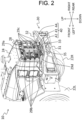
- Fig. 2 is a perspective view of a main part of the wheel loader 10 as viewed from a rear side.
- a rear grill 28 is mounted on a back surface of the engine grilled compartment 24.
- the rear grill 28 allows the communication of air between the outside of the wheel loader 10 and the inner space of the engine grilled compartment 24.
- the rear grill 28 includes a center pillar 29a, a plurality of left side beams 29b, a plurality of right side beams 29c, and a plurality of inclined beams 29d.
- the rear grill 28 allows the circulation of air through gaps formed between the center pillar 29a, the plurality of left side beams 29b, the plurality of right side beams 29c, and the plurality of inclined beams 29d.
- the center pillar 29a extends in the vertical direction at the center of the vehicle body in a vehicle width direction (a lateral direction).
- the plurality of left side beams 29b respectively extend from a left surface of the center pillar 29a toward a left side at positions spaced apart from each other in a vertical direction.
- the plurality of right side beams 29c respectively extend from a right surface of the center pillar 29a toward a right side at positions spaced apart from each other in a vertical direction.
- the inclined beam 29d extends obliquely in a leftward and downward direction from the lowermost left side beam 29b.
- the rear grill 28 may include the inclined beam 29d that extends obliquely in a rightward and downward direction from the lowermost right side beam 29c.
- the counterweight 30 is an example of a defining member that defines a rear end of the wheel loader 10 (the rear frame 12).
- the defining member is the counterweight 30 (a heavy object) that is provided for taking a weight balance with the front working device 16.
- Fig. 3 is a perspective view of the counterweight 30 as viewed from a front side.
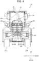
- Fig. 4 is a back view of the wheel loader 10.
- a rear end of the counterweight 30 is positioned at a rearmost side among constitutional components of the wheel loader 10.
- the counterweight 30 is disposed over an entire region of the rear frame 12 in a vehicle width direction.
- the counterweight 30 is positioned in a region in which at least the rear grill 28 is disposed within the rear frame 12 in a vehicle width direction and below the rear grill 28.
- the counterweight 30 includes a support base 31 and a bumper 32.
- the support base 31 is disposed at the center of the counterweight 30 in the vehicle width direction.
- the support base 31 is disposed below the bumper 32 and in front of a rear end of the bumper 32.
- a towing pin holding hole 33 that opens upward is formed in an upper surface of the support base 31.
- the towing pin holding hole 33 holds a towing pin 35 described later in a state where the towing pin 35 is insertable and removable into and from the towing pin holding hole 33 in a vertical direction.
- the bumper 32 extends in the lateral direction over an entire region of the counterweight 30 in the vehicle width direction.
- the bumper 32 is disposed above the support base 31 and behind the support base 31. Further, a rear end of the bumper 32 is disposed on a rearmost side of the counterweight 30 (that is, one constitutional element among the constitutional components of the wheel loader 10), and an object that approaches the wheel loader 10 firstly impinges on the rear end of the bumper 32.
- a gap is formed between the support base 31 and the bumper 32 in a vertical direction.
- the gap formed between the support base 31 and the bumper 32 is exposed to an area behind the wheel loader 10.
- a wire (a towing jig) that engages with the towing pin 35 held in the towing pin holding hole 33 is extended to an area behind the wheel loader 10 through the gap.
- a towing pin insertion hole 34 is formed in the bumper 32 in a vertically penetrating manner.
- the towing pin holding hole 33 and the towing pin insertion hole 34 are formed at a position in which the towing pin holding hole 33 and the towing pin insertion hole 34 overlap with each other as viewed in a vertical direction. That is, the towing pin 35 is vertically insertable and removable with respect to the towing pin holding hole 33 through the towing pin insertion hole 34.
- the towing pin 35 is used in a state where the towing pin 35 engages with a wire provided to another vehicle when the wheel loader 10 tows another vehicle.
- the towing pin 35 is formed of a pin body 36 having a circular columnar shape, and a grip portion 37 that is mounted on an upper end of the pin body 36.
- the towing pin 35 is inserted into or removed from the towing pin holding hole 33 through the towing pin insertion hole 34 in a state where a portion of the towing pin 35 on a grip portion 37 side forms an upper end portion of the towing pin 35.
- the wheel loader 10 further includes a rearward detection device 40.
- the rearward detection device 40 detects an object positioned behind the wheel loader 10 (for example, an obstacle, an operator, another vehicle), and outputs a detection signal indicating the result of the detection to a controller (not illustrated in the drawing) via a harness 43 (see Fig. 3 ).
- the controller notifies the operator in the cab 23 of the presence of the object based on the detection signal outputted from the rearward detection device 40.
- the rearward detection device 40 is disposed in front of a rear end of the counterweight 30 and behind constitutional components (including the engine grilled compartment 24) of the wheel loader 10 except for the counterweight 30. More specifically, as illustrated in Fig. 5(A) and Fig. 6(A) , in a case where a support plate 42 described later is detectable, the rear end of a millimeter wave radar 41 described later is disposed in front of the rear end of the counterweight 30 and behind the engine grilled compartment 24. Further, as illustrated in Fig. 2 to Fig. 4 , the rearward detection device 40 is supported by an upper surface of the bumper 32 at the center of the counterweight 30 in the vehicle width direction and behind the towing pin insertion hole 34.
- the rearward detection device 40 is disposed such that the rearward detection device 40 overlaps with a portion of the rear grill 28. More specifically, an external profile line of the rearward detection device 40 (a bracket 44 described later) overlaps with a portion of the plurality of beams 29b to 29d of the rear grill 28 (more specifically, the left and right inclined beams 29d).
- the rearward detection device 40 is disposed at the same position as the towing pin 35 held by the towing pin holding hole 33 in the vehicle width direction of the wheel loader 10 (that is, the center of the wheel loader 10 in the vehicle width direction).
- the rearward detection device 40 is disposed, with respect to the height direction (vertical direction) of the wheel loader 10, above the towing pin 35 held by the towing pin holding hole 33 (more specifically, the gap between the support base 31 from which the towing pin 35 is exposed and the bumper 32).
- the rearward detection device 40 that is disposed at the position illustrated in Fig. 4 obstructs an insertion/removal operation of the towing pin 35 with respect to the towing pin holding hole 33. This problem becomes particularly conspicuous in a small sized wheel loader in which it is necessary to shorten a distance between the rear grill 28 and the rearward detection device 4.
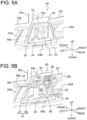
- Fig. 5 is a perspective view of the rearward detection device 40 as viewed from a rear side.
- Fig. 6 is a perspective view of the rearward detection device 40 as viewed from a front side.
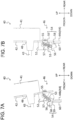
- Fig. 7 is a cross sectional view of a lock mechanism 46.
- the rearward detection device 40 includes a millimeter wave radar 41, a support plate 42, a harness 43, a bracket 44, a harness holding portion 45, and the lock mechanism 46.
- the millimeter wave radar 41 is an object detection device (sensor) that detects an object existing behind the wheel loader 10.
- the millimeter wave radar 41 outputs a millimeter wave rearward and receives the millimeter wave reflected by the object.
- a specific example of the object detection device is not limited to a millimeter wave radar 41 and may be a camera, a stereoscopic camera, a LiDAR and the like.
- the support plate 42 is a plate shaped member that supports the millimeter wave radar 41.
- the support plate 42 has a trapezoidal shape that corresponds to a shape of an opening 50 formed in a bracket 44 described later.
- the support plate 42 is supported by the bracket 44 in a rotatable (movable, changeable) manner.
- a support plate manipulation hole 47 that penetrates the support plate 42 in a thickness direction is formed in the support plate 42 at a position that differs from a position in which the millimeter wave radar 41 is supported.
- the support plate manipulation hole 47 is a portion in which a finger of an operator is inserted at the time of rotating the support plate 42.
- the millimeter wave radar 41 is mounted on a back surface (a surface that faces an area behind the wheel loader 10 when the millimeter wave radar 41 is in a detection capable state) of the support plate 42 at the center of the support plate 42.
- a detection capable state Fig. 5(A)
- the harness 43 is pulled out toward an area on a side in front of the wheel loader 10 through the penetration hole 48 that penetrates the support plate 42 in a thickness direction.
- the bracket 44 is supported by the counterweight 30 above and behind the towing pin 35 held by the towing pin holding hole 33.
- the bracket 44 according to the present embodiment is fixed (fastened) to an upper surface of the bumper 32 by bolts 49a, 49b at both sides of the towing pin insertion hole 34 in the vehicle width direction of the wheel loader 10.
- the bracket 44 supports the support plate 42 for supporting the millimeter wave radar 41 between a detection capable state indicated in Fig. 5(A) and Fig. 6 (A) and a retraction state indicated in Fig. 5(B) and Fig. 6(B) in a rotatable (movable, changeable) manner.
- the bracket 44 is a frame having a trapezoidal shape that is formed of: an upper side 44a and a lower side 44b that are parallel to each other; a left side 44c that connects a left end of the upper side 44a and a left end of the lower side 44b; and a right side 44d that connects a right end of the upper side 44a and a right end of the lower side 44b.
- a size of the upper side 44a is set shorter than a size of the lower side 44b.
- the bracket 44 is supported by the bumper 32 such that the left side 44c and the right side 44d overlap with the left and right inclined beams 29d. Further, as illustrated in Fig.
- a surface of the bracket 44 that is fixed (fastened) to an upper surface of the bumper 32 by bolts 49a, 49b is cut away so as to open an upper side of the towing pin holding hole 33 and an upper side of the towing pin insertion hole 34.
- An opening 50 is formed in the bracket 44 in a state where the opening 50 penetrates the bracket 44 in a thickness direction (a longitudinal direction of the wheel loader 10).
- the opening 50 is a space having a trapezoidal shape that is surrounded by the upper side 44a, the lower side 44b, the left side 44c and the right side 44d.
- the bracket 44 supports the support plate 42 that supports the millimeter wave radar 41 by way of a hinge 51 fixed to a lower end of the upper side 44a. That is, the support plate 42 that supports the millimeter wave radar 41 is configured to be rotatable about a rotation axis extending in the vehicle width direction of the wheel loader 10 by the hinge 51.
- a harness holding portion 45 is mounted on the bracket 44.
- the harness holding portion 45 according to the present embodiment is disposed on a front surface side of the right side 44d (that is, a position avoiding the center of the opening 50).
- the harness holding portion 45 is disposed at the substantially center of the right side 44d in the vertical direction.
- the harness holding portion 45 is a through hole that penetrates the right side 44d for fixing a harness holding member (for example, a binding band).
- the harness 43 is supported by the bracket 44 at the position avoiding the center of the opening 50 by being fastened to the harness holding member that is fixed to the harness holding portion 45. Further, the harness holding member that is fixed to the harness holding portion 45 holds the harness 43 with a fastening force to an extent that the harness 43 is movable in the longitudinal direction following the rotation of the support plate 42 that supports the millimeter wave radar 41.
- the opening 50 formed in the bracket 44 is closed by the support plate 42. That is, the detection capable state of the support plate 42 is a state where the opening 50 is closed (that is, a state where a manipulation of the towing pin 35 by an operator through the opening 50 is prevented).
- the millimeter wave radar 41 that is supported by the support plate 42 on a detection capable state is disposed behind the wheel loader 10 and, at the same time, is disposed behind a surface (an antenna surface) and is directed in a horizontal direction such that the millimeter wave radar 41 can output a millimeter wave using the horizontal direction as the center and can receive the millimeter wave reflected from an object.
- the detection capable state of the support plate 42 is a state that allows the millimeter wave radar 41 to detect an object existing behind the wheel loader10.
- the detection capable state of the support plate 42 may be also referred to as a position (a detection capable position) of the support plate 42 in which the manipulation of the towing pin 35 is prevented and, at the same time, the millimeter wave radar 41 can detect an object.
- an operator who intends to manipulate the towing pin 35 inserts his/her finger into the support plate manipulation hole 47 illustrated in Fig. 5(A) and Fig. 6(A) , and pulls up the support plate 42 rearward and upward.
- the support plate 42 rotates from a detection capable state illustrated in Fig. 5(A) and Fig. 6(A) to a retraction state illustrated in Fig. 5(B) and Fig. 6(B) such that the support plate 42 is so as to flip up itself rearward and upward.
- the harness 43 is pulled out rearward following the support plate 42.
- the opening 50 is opened when the support plate 42 is in a retraction state. That is, the retraction state of the support plate 42 is a state where the opening 50 is opened (in other words, a state where the manipulation of the towing pin held by the towing pin holding hole 33 is allowed).
- the support plate 42 in the retraction state supports the millimeter wave radar 41 such that the surface (the antenna surface) of the millimeter wave radar 41 is directed upward. That is, the retraction state of the support plate 42 is the state where the millimeter wave radar 41 cannot detect an object existing behind the wheel loader 10.
- the retraction state of the support plate 42 may also be a state where an object behind the wheel loader 10 can be detected by the millimeter wave radar 41.
- the retraction state of the support plate 42 may be also referred to the position (retraction position) of the support plate 42 in which an operator is allowed to manipulate the towing pin 35 through the opening 50 formed in the bracket 44 from behind the wheel loader 10.
- the operator grips the grip portion 37 and pulls up the grip portion 37 upward through the opening 50 in a state where the support plate 42 is held in a retraction state.
- the operator winds the wire to around the towing pin 35 through the gap formed between the support base 31 and the lower end of the towing pin 35.
- the operator grips the grip portion 37 and pushes down the grip portion 37 downward through the opening 50. Accordingly, the towing pin 35 in a state where the wire engages with the towing pin 35 is held in the towing pin holding hole 33.
- the support plate 42 is automatically brought into a detection capable state due to gravity.
- the above-mentioned series of operations may be performed by a single operator or may be performed by a plurality of operators.
- the lock mechanism 46 is a mechanism that locks the support plate 42 on which the millimeter wave radar 41 is supported in a detection capable state.
- the lock mechanism 46 is mounted on a front surface of the support plate 42 (a surface of the support plate 42 that is directed toward a front side of the wheel loader 10 is in a detection capable state) at a position that corresponds to a lower side 44b that opposedly faces the upper side 44a to which the hinge 51 is fixed.
- the lock mechanism 46 is constituted of a fixing block 52, a pivot shaft 53, a lock arm 54, spring fixing shafts 55,56, and a coil spring 57(a biasing member).
- the fixing block 52 is disposed below the millimeter wave radar 41, and is fixed to a front surface of the support plate 42 (a surface on a side opposite to a support surface for the millimeter wave radar 41).
- the pivot shaft 53 is fixed to a side surface of the fixing block 52 in a state where the pivot shaft 53 is disposed in an extending manner in a vehicle width direction of the wheel loader 10.
- the lock arm 54 is rotatably supported by the pivot shaft 53.
- the spring fixing shaft 55 is fixed to a side surface of the fixing block 52 to which the pivot shaft 53 is fixed.
- the coil fixing shaft 56 is fixed to the lock arm 54.
- the spring fixing shaft 56 s disposed at a position closer to the pivot shaft 53 than the spring fixing shaft 55.
- One end of the coil spring 57 is fixed to the spring fixing shaft 55, and the other end of the coil spring 57 is fixed to the spring fixing shaft 56.
- the lock arm 54 has a lock lug 58 and an engaging pawl 59.
- the lock arm 54 rotates about the pivot shaft 53 between an unlocked posture illustrated in Fig. 7(A) and a locked posture illustrated in Fig. 7 (B) .
- the unlocked posture is a posture of the lock arm 54 in which a rotation trajectory of the lock lug 58 is disposed above (inside) a lock plate 60 disposed on a lower side 44b, and a rotation trajectory of the engaging pawl 59 is disposed below (outside) the lock plate 60.
- the locked posture is a posture of the lock arm 54 in which the rotation trajectory of the lock lug 58 is below (outside) the lock plate 60 and the rotation trajectory of the engaging pawl 59 is above (inside) the lock plate 60.
- the coil spring 57 biases the lock arm 54 toward either a non-locked posture or a locked posture in response to a positional relationship with the pivot shaft 53.
- the direction of the biasing force of the lock arm 54 generated by the coil spring 57 is switched due to the rotation of the lock arm 54 as described below.
- a biasing force of the coil spring 57 is increased (that is, the coil spring 57 is elongated).
- the coil spring 57 biases the lock arm 54 toward a non-locked posture. That is, as viewed from an extending direction of the pivot shaft 53, when the coil spring 57 passes the pivot shaft 53 in the first direction (a clockwise direction in an example illustrated in Fig. 7 ), the coil spring 57 biases the lock arm 54 toward a non-locked posture.
- the lock arm 54 takes a locked posture.
- the support plate 42 is brought into contact with the back surface of the lock plate 60, and the lock lug 58 is brought into contact with the front surface of the lock plate 60 so that the support plate 42 is locked in a detection capable state.
- an external force is applied to the support plate 42 so as to make the support plate 42 approach to a retraction state from the state illustrated in Fig. 7(B) .
- an operator puts his/her finger in the support plate manipulation hole 47 and pulls the support plate 42 in a back surface direction, the lock arm 54 rotates in the clockwise direction against a biasing force of the coil spring 57 by a reactional force that the lock lug 58 receives from the lock plate 60.
- the coil spring 57 passes the pivot shaft 53 in a clockwise direction
- the coil spring 57 biases the lock arm 54 to a non-locked posture (that is, the direction of a biasing force of the coil spring 57 is switched).
- a rotation trajectory of the lock lug 58 moves above the lock plate 60 so that locking by the lock mechanism 46 is released.
- the operator can rotate the support plate 42 to a retraction state.
- the configuration is adopted where the posture of the support plate 42 that supports the millimeter wave radar 41 can be changed between a detection capable state and a retraction state. Accordingly, when the wheel loader 10 is operated (when the wheel loader 10 is travelling or when the wheel loader 10 is performing a work using the front working device 16), an area behind the wheel loader 10 can be monitored. Further, it is possible to prevent the rearward detection device 40 from obstructing an operation of an operator who inserts or removes the towing pin 35. As a result, it is possible to provide the wheel loader 10 that can mount the rearward detection device 40 on the rear end of the vehicle body without impairing the operability of the towing pin 35.
- the support plate 42 is locked in a detection capable state by the lock mechanism 46. Accordingly, it is possible to prevent the support plate 42 from inadvertently rotating toward a retraction state due to vibrations or the like generated at the time of operating the wheel loader 10. Further, by adopting the lock mechanism 46 having the configuration illustrated in Fig. 7 , a locking operation and a locking release operation of the millimeter wave radar 41 can be simplified. However, provided that the support plate 42 can be locked in a detection capable state, the specific configuration of the lock mechanism 46 is not limited to the example illustrated in Fig. 7 .
- the rearward detection device 40 with respect to the constitutional components of the wheel loader 10, by disposing the rearward detection device 40 behind all constitutional components except for the counterweight 30, an area behind the rearward detection device 40 is opened and hence, the rearward detection device 40 can ensure a wide monitoring area behind the wheel loader 10. (That is, the millimeter wave is not interrupted by vehicle body mounting components).
- the millimeter wave is not interrupted by vehicle body mounting components.
- the object is brought into contact with the bumper 32 that protrudes rearward from the vehicle body than the millimeter wave radar 41 and hence, a load applied to the millimeter wave radar 41 can be reduced whereby the occurrence of failure in the rearward detection device 40 can be prevented.
- the millimeter wave radar 41 can be arranged at the position suitable for rearward monitoring without changing a longitudinal length of the vehicle body.
- the upper side 44a of the bracket 44 that overlaps with the cooling fan 27 as viewed in the air supply direction (the vehicle body longitudinal direction) is formed shorter than the lower side 44b of the bracket 44 that does not overlap with the cooling fan 27 as viewed from the air supply direction (vehicle body longitudinal direction) of the cooling fan 27, and the left side 44c and the right side 44d of the bracket 44 overlap with the inclined beams 29d.
- the rearward detection device 40 can be supported by the bumper 32 in a stable manner. Further, the millimeter wave radar 41 is disposed at the position close to a ground. Accordingly, compared to a case where the millimeter wave radar 41 is mounted on an upper portion of the engine grilled compartment 24, a wiping-out operation of dust adhering to the millimeter wave radar 41 can be easily performed.
- the harness 43 is held at the position avoiding the center of the opening 50. Accordingly, the opening 50 that is formed in the bracket 44 for an operation of inserting into or removing the towing pin 35 from the towing pin holding hole 33 without removing the harness 43 from the millimeter wave radar 41 can ensure a large area.
- a method of moving the support plate 42 between a detection capable state and a retraction state is not limited to the previously mentioned example.
- the millimeter wave radar 41 may be configured such that the millimeter wave radar 41 is rotatable by way of a hinge mounted on the lower side 44b, the left side 44c, or the right side 44d.
- the millimeter wave radar 41 may be configured such that the millimeter wave radar 41 is slidable in the vertical direction or in the lateral direction with respect to the bracket 44.
- the configuration that enables or disenables monitoring of an area behind the wheel loader 10 by the rearward detection device 40 and the configuration that enables or disenables an operation of the towing pin 35 are not limited to the above-mentioned examples.
- the rearward detection device 40 may be detachably configured with respect to the vehicle body (more specifically, the counterweight 30). That is, the support plate 42 may be configured to retractable in the manipulation direction (the rearward and upward direction in the present embodiment) of the towing pin 35 when the towing pin 35 is manipulated.
Landscapes
- Engineering & Computer Science (AREA)
- Structural Engineering (AREA)
- Mining & Mineral Resources (AREA)
- Civil Engineering (AREA)
- General Engineering & Computer Science (AREA)
- Mechanical Engineering (AREA)
- Transportation (AREA)
- Computer Networks & Wireless Communication (AREA)
- Physics & Mathematics (AREA)
- General Physics & Mathematics (AREA)
- Radar, Positioning & Navigation (AREA)
- Remote Sensing (AREA)
- Component Parts Of Construction Machinery (AREA)
Abstract
Description
- The present invention relates to a work vehicle that includes a towing pin and a rearward detection device.
- With respect to a work vehicle used on a terrain, there is a case where a work vehicle is required to tow another vehicle. To cope with such a case, there has been known a work vehicle that includes a towing pin that is supported by a center of a rear portion of a vehicle body in a vehicle width direction in an insertable and removable manner and engages with a wire for towing another vehicle (Patent literature 1).
- There also exists a work vehicle on which a camera for imaging an area behind a vehicle body of the work vehicle is mounted. With such a configuration, an operator in an operator's cabin can check a situation behind a vehicle body. Patent literature 1 discloses the configuration in which a wide angle camera is mounted on an upper portion of a rear side of the vehicle body in a state where the camera is mounted in an obliquely downwardly inclined manner so that the camera can perform imaging in a wide range from a rear end of the vehicle body (a near distance) to the area behind the vehicle body (a far distance). As a detection device for detecting a situation behind a vehicle body, besides the camera described in the patent literature 1, there may be a case where a millimeter wave radar, a light detection and ranging (LiDAR) device or the like is used for detecting the presence or the non-presence of an object (for example, an obstacle, a worker, another vehicle) behind the vehicle body.
- Patent Literature 1:
Japanese Unexamined Patent Application Publication No. 2012-184600 - In a case where a detection device that is not compatible with a detection range (imaging range) of a large angle is mounted on the vehicle body in consideration of ease of accessibility and a cost, to detect an area behind the vehicle body (a far distance) from a rear end of a vehicle (a near distance) using one detection device, it is desirable that a detection device is disposed on a counterweight that forms the rear end of the vehicle body and the detection direction is set in a substantially horizontal direction. However, the towing pin is mounted on the counterweight. Accordingly, in a case where an attempt is made to mount the rearward detection device within a limited size of the vehicle body, there is a concern that the rearward detection device hinders the insertion or the removal of the towing pin.
- The present invention has been made in view of the above-mentioned circumstances, and it is an object of the present invention to provide a work vehicle in which a rearward detection device can be mounted on a rear end of a vehicle body without impairing operability of a towing pin.
- To solve the problem, the present invention has configurations described such that a work vehicle includes:
a vehicle body; a counterweight that defines a rear end of the vehicle body; and a towing pin that is held in a towing pin holding hole formed in the counterweight in a state where the towing pin is removable upwardly, the towing pin being engageable with a towing jig for towing another vehicle. The work vehicle further includes a rearward detection device that detects an object existing behind the vehicle body. The rearward detection device includes: a bracket that is supported by the counterweight above the towing pin held in the towing pin holding hole; a support plate that is supported by the bracket; and an object detection device that is supported by the support plate. The support plate is configured to be retractable in a manipulation direction of the towing pin when the towing pin is manipulated. - According to the present invention, it is possible to provide a work vehicle in which a rearward detection device can be mounted on a rear end of a vehicle body without impairing operability of a towing pin.
- Incidentally, problems, configurations, and effects other than those described above will be clarified by the following description of embodiments.
-
-
Fig. 1 is a side view of a wheel loader according to an embodiment. -
Fig. 2 is a perspective view of a main part of the wheel loader as viewed from a rear side. -
Fig. 3 is a perspective view of a counterweight as viewed from a front side. -
Fig. 4 is a back view of the wheel loader. -
Fig. 5 is a perspective view of a rearward detection device as viewed from a rear side. -
Fig. 6 is a perspective view of the rearward detection device as viewed from a front side. -
Fig. 7 is a cross sectional view of a lock mechanism. - Hereinafter, with reference to drawings, a
wheel loader 10 that is one example of a work vehicle according to the present invention is described. In the specification, unless otherwise particularly specified, "front", "rear", "left" and "right" are determined using a viewing point of a worker who rides on thewheel loader 10 and manipulates thewheel loader 10. A specific example of the work vehicle is not limited to thewheel loader 10, and the work vehicle may be a dump truck, a hydraulic excavator, a crane vehicle or the like. -
Fig. 1 a side view of thewheel loader 10 according to the present embodiment. As illustrated inFig. 1 , thewheel loader 10 has a vehicle body formed of afront frame 11 and arear frame 12. Thefront frame 11 and therear frame 12 are rotatably connected to each other in a lateral direction by acenter pin 13. Further, thefront frame 11 and therear frame 12 are connected to each other by a pair of left andright steering cylinders steering cylinders - Out of the pair of
steering cylinders front frame 11 is bent in the lateral direction with respect to therear frame 12 about thecenter pin 13. With such an operation, a relative mounting angle between thefront frame 11 and therear frame 12 is changed so that the vehicle body is bent and the direction of the vehicle body changes. That is, thewheel loader 10 is of an articulated type wheel loader in which thefront frame 11 and therear frame 12 are bent about thecenter pin 13. - The
front frame 11 supports a pair of left and rightfront tires lift arm 17, abucket 18, a pair oflift arm cylinders 19, abucket cylinder 20 and abell crank 21. - The
lift arm 17 extends in the longitudinal direction. To be more specific, a front end of thelift arm 17 is rotatably connected to thebucket 18, and a rear end of thelift arm 17 is rotatably connected to thefront frame 11. Thelift arm 17 rotates in a vertical direction (performs an upward and downward tilting) by extension and retraction of the pair oflift arm cylinders 19. - The
bucket 18 has a recessed space capable of accommodating a load (such as soil and sands). Thebucket 18 is rotatably (tiltably or dumpably) supported by a front end of thelift arm 17. More specifically, thebucket 18 is rotated in a vertical direction due to the rotation of abell crank 21 brought about by extension or retraction of thebucket cylinder 20. - The
rear frame 12 supports a pair of left and rightrear tires counterweight 30. - An inner space in which an operator who manipulates the
wheel loader 10 is seated is formed in thecab 23. In the inside of thecab 23, a seat (not illustrated in the drawing) on which the operator is seated, and a manipulation device (not illustrated in the drawing) that the operator seated on the seat manipulates are disposed. When the operator seated in thecab 23 manipulates the manipulation device, thewheel loader 10 travels and the front working device 16 is operated. - The engine grilled
compartment 24 is supported by therear frame 12 behind thecab 23 and in front of a rearmost end of thecounterweight 30. The engine grilledcompartment 24 has an inner space that accommodates constitutional components for driving the wheel loader 10 (for example, anengine 25, aradiator 26, and a cooling fan 27). - The
engine 25 generates a drive force for operating thewheel loader 10. By transmitting the drive force of theengine 25,front tires rear tires wheel loader 10 travels. Theradiator 26 supplies cooling water to theengine 25, cooling water discharged from theengine 25 is subjected to a heat exchange with cooling air, and cooling water that is subjected to the heat exchange is returned to theengine 25 again. Thecooling fan 27 supplies cooling air to theradiator 26. -
Fig. 2 is a perspective view of a main part of thewheel loader 10 as viewed from a rear side. As illustrated inFig. 2 , arear grill 28 is mounted on a back surface of the engine grilledcompartment 24. Therear grill 28 allows the communication of air between the outside of thewheel loader 10 and the inner space of the engine grilledcompartment 24. More specifically, therear grill 28 includes acenter pillar 29a, a plurality ofleft side beams 29b, a plurality ofright side beams 29c, and a plurality ofinclined beams 29d. With such a configuration, therear grill 28 allows the circulation of air through gaps formed between thecenter pillar 29a, the plurality ofleft side beams 29b, the plurality ofright side beams 29c, and the plurality ofinclined beams 29d. - The
center pillar 29a extends in the vertical direction at the center of the vehicle body in a vehicle width direction (a lateral direction). The plurality ofleft side beams 29b respectively extend from a left surface of thecenter pillar 29a toward a left side at positions spaced apart from each other in a vertical direction. The plurality of right side beams 29c respectively extend from a right surface of thecenter pillar 29a toward a right side at positions spaced apart from each other in a vertical direction. Theinclined beam 29d extends obliquely in a leftward and downward direction from the lowermostleft side beam 29b. Further, although not illustrated in the drawing, therear grill 28 may include theinclined beam 29d that extends obliquely in a rightward and downward direction from the lowermostright side beam 29c. - The
counterweight 30 is an example of a defining member that defines a rear end of the wheel loader 10 (the rear frame 12). In this embodiment, the defining member is the counterweight 30 (a heavy object) that is provided for taking a weight balance with the front working device 16. -
Fig. 3 is a perspective view of thecounterweight 30 as viewed from a front side.Fig. 4 is a back view of thewheel loader 10. As illustrated inFig. 1 andFig. 2 , a rear end of thecounterweight 30 is positioned at a rearmost side among constitutional components of thewheel loader 10. Further, as illustrated inFig. 2 andFig. 4 , thecounterweight 30 is disposed over an entire region of therear frame 12 in a vehicle width direction. Thecounterweight 30 is positioned in a region in which at least therear grill 28 is disposed within therear frame 12 in a vehicle width direction and below therear grill 28. As illustrated inFig. 2 to Fig. 4 , thecounterweight 30 includes asupport base 31 and abumper 32. - The
support base 31 is disposed at the center of thecounterweight 30 in the vehicle width direction. Thesupport base 31 is disposed below thebumper 32 and in front of a rear end of thebumper 32. A towingpin holding hole 33 that opens upward is formed in an upper surface of thesupport base 31. The towingpin holding hole 33 holds a towingpin 35 described later in a state where the towingpin 35 is insertable and removable into and from the towingpin holding hole 33 in a vertical direction. - The
bumper 32 extends in the lateral direction over an entire region of thecounterweight 30 in the vehicle width direction. Thebumper 32 is disposed above thesupport base 31 and behind thesupport base 31. Further, a rear end of thebumper 32 is disposed on a rearmost side of the counterweight 30 (that is, one constitutional element among the constitutional components of the wheel loader 10), and an object that approaches thewheel loader 10 firstly impinges on the rear end of thebumper 32. - A gap is formed between the
support base 31 and thebumper 32 in a vertical direction. The gap formed between thesupport base 31 and thebumper 32 is exposed to an area behind thewheel loader 10. A wire (a towing jig) that engages with the towingpin 35 held in the towingpin holding hole 33 is extended to an area behind thewheel loader 10 through the gap. - As illustrated in
Fig. 3 , a towingpin insertion hole 34 is formed in thebumper 32 in a vertically penetrating manner. The towingpin holding hole 33 and the towingpin insertion hole 34 are formed at a position in which the towingpin holding hole 33 and the towingpin insertion hole 34 overlap with each other as viewed in a vertical direction. That is, the towingpin 35 is vertically insertable and removable with respect to the towingpin holding hole 33 through the towingpin insertion hole 34. - The towing
pin 35 is used in a state where the towingpin 35 engages with a wire provided to another vehicle when thewheel loader 10 tows another vehicle. As illustrated inFig. 5(B) andFig. 6 (B) , the towingpin 35 is formed of apin body 36 having a circular columnar shape, and agrip portion 37 that is mounted on an upper end of thepin body 36. The towingpin 35 is inserted into or removed from the towingpin holding hole 33 through the towingpin insertion hole 34 in a state where a portion of the towingpin 35 on agrip portion 37 side forms an upper end portion of the towingpin 35. - First, when an operator who grips the
grip portion 37 pushes down the towingpin 35 in the towingpin insertion hole 34, a lower end portion of the towingpin 35 is inserted into the towingpin holding hole 33. As a result, the towingpin 35 is supported by thesupport base 31. At this stage of the operation, a portion of thepin body 36 passes through the gap formed between thesupport base 31 and thebumper 32 in a vertical direction, and is exposed to an area behind thewheel loader 10. Thegrip portion 37 is accommodated in the towingpin insertion hole 34 below an upper end of thebumper 32. - On the other hand, when the operator who grips the
grip portion 37 pulls up the towingpin 35 in the towingpin insertion hole 34, a lower end portion of the towingpin 35 is removed from the towingpin holding hole 33. As a result, a gap is formed between thesupport base 31 and the towingpin 35 in the vertical direction. The operator can make a wire engage (latch) with thepin body 36 through the gap. Then, the operator pushed down the towingpin 35 again so that the towingpin 35 with which the wire engages is supported by thesupport base 31. In the operation of making the wire engage with the towingpin 35, it is not necessary to pull up the towingpin 35 to a position in which thetowing pin 35 is completely removed from the towingpin insertion hole 34. That is, it is sufficient to pull up the towingpin 35 in the upward direction by forming an amount of gap that allows the insertion of the wire between thesupport base 31 and the towingpin 35. - As illustrated in
Fig. 1 , thewheel loader 10 according to the present embodiment further includes arearward detection device 40. Therearward detection device 40 detects an object positioned behind the wheel loader 10 (for example, an obstacle, an operator, another vehicle), and outputs a detection signal indicating the result of the detection to a controller (not illustrated in the drawing) via a harness 43 (seeFig. 3 ). The controller notifies the operator in thecab 23 of the presence of the object based on the detection signal outputted from therearward detection device 40. - As illustrated in
Fig. 1 , therearward detection device 40 is disposed in front of a rear end of thecounterweight 30 and behind constitutional components (including the engine grilled compartment 24) of thewheel loader 10 except for thecounterweight 30. More specifically, as illustrated inFig. 5(A) andFig. 6(A) , in a case where asupport plate 42 described later is detectable, the rear end of amillimeter wave radar 41 described later is disposed in front of the rear end of thecounterweight 30 and behind the engine grilledcompartment 24. Further, as illustrated inFig. 2 to Fig. 4 , therearward detection device 40 is supported by an upper surface of thebumper 32 at the center of thecounterweight 30 in the vehicle width direction and behind the towingpin insertion hole 34. - Further, in a state where the
wheel loader 10 is viewed from a rear side as illustrated inFig. 4 , therearward detection device 40 is disposed such that therearward detection device 40 overlaps with a portion of therear grill 28. More specifically, an external profile line of the rearward detection device 40 (abracket 44 described later) overlaps with a portion of the plurality ofbeams 29b to 29d of the rear grill 28 (more specifically, the left and rightinclined beams 29d). - Further, as illustrated in
Fig. 4 , therearward detection device 40 is disposed at the same position as the towingpin 35 held by the towingpin holding hole 33 in the vehicle width direction of the wheel loader 10 (that is, the center of thewheel loader 10 in the vehicle width direction). On the other hand, therearward detection device 40 is disposed, with respect to the height direction (vertical direction) of thewheel loader 10, above the towingpin 35 held by the towing pin holding hole 33 (more specifically, the gap between thesupport base 31 from which thetowing pin 35 is exposed and the bumper 32). - That is, even in a state where the
rearward detection device 40 is mounted, it is possible to make the wire engage with the towingpin 35. On the other hand, therearward detection device 40 that is disposed at the position illustrated inFig. 4 obstructs an insertion/removal operation of the towingpin 35 with respect to the towingpin holding hole 33. This problem becomes particularly conspicuous in a small sized wheel loader in which it is necessary to shorten a distance between therear grill 28 and the rearward detection device 4. -
Fig. 5 is a perspective view of therearward detection device 40 as viewed from a rear side.Fig. 6 is a perspective view of therearward detection device 40 as viewed from a front side.Fig. 7 is a cross sectional view of alock mechanism 46. As illustrated inFig. 5 to Fig. 7 , therearward detection device 40 includes amillimeter wave radar 41, asupport plate 42, aharness 43, abracket 44, aharness holding portion 45, and thelock mechanism 46. - The
millimeter wave radar 41 is an object detection device (sensor) that detects an object existing behind thewheel loader 10. Themillimeter wave radar 41 outputs a millimeter wave rearward and receives the millimeter wave reflected by the object. However, a specific example of the object detection device is not limited to amillimeter wave radar 41 and may be a camera, a stereoscopic camera, a LiDAR and the like. - The
support plate 42 is a plate shaped member that supports themillimeter wave radar 41. Thesupport plate 42 has a trapezoidal shape that corresponds to a shape of anopening 50 formed in abracket 44 described later. Thesupport plate 42 is supported by thebracket 44 in a rotatable (movable, changeable) manner. Further, in thesupport plate 42, a supportplate manipulation hole 47 that penetrates thesupport plate 42 in a thickness direction is formed in thesupport plate 42 at a position that differs from a position in which themillimeter wave radar 41 is supported. The supportplate manipulation hole 47 is a portion in which a finger of an operator is inserted at the time of rotating thesupport plate 42. - The
millimeter wave radar 41 is mounted on a back surface (a surface that faces an area behind thewheel loader 10 when themillimeter wave radar 41 is in a detection capable state) of thesupport plate 42 at the center of thesupport plate 42. When thesupport plate 42 is in a detection capable state (Fig. 5(A) ), a surface of themillimeter wave radar 41 that outputs and receives a millimeter wave is exposed to a region on a side behind thewheel loader 10. Theharness 43 is pulled out toward an area on a side in front of thewheel loader 10 through thepenetration hole 48 that penetrates thesupport plate 42 in a thickness direction. - The
bracket 44 is supported by thecounterweight 30 above and behind the towingpin 35 held by the towingpin holding hole 33. Thebracket 44 according to the present embodiment is fixed (fastened) to an upper surface of thebumper 32 bybolts pin insertion hole 34 in the vehicle width direction of thewheel loader 10. Thebracket 44 supports thesupport plate 42 for supporting themillimeter wave radar 41 between a detection capable state indicated inFig. 5(A) andFig. 6 (A) and a retraction state indicated inFig. 5(B) andFig. 6(B) in a rotatable (movable, changeable) manner. - The
bracket 44 is a frame having a trapezoidal shape that is formed of: anupper side 44a and alower side 44b that are parallel to each other; aleft side 44c that connects a left end of theupper side 44a and a left end of thelower side 44b; and aright side 44d that connects a right end of theupper side 44a and a right end of thelower side 44b. In the vehicle width direction of thewheel loader 10, a size of theupper side 44a is set shorter than a size of thelower side 44b. When thewheel loader 10 is viewed from a rear side, thebracket 44 is supported by thebumper 32 such that theleft side 44c and theright side 44d overlap with the left and rightinclined beams 29d. Further, as illustrated inFig. 3 , a surface of thebracket 44 that is fixed (fastened) to an upper surface of thebumper 32 bybolts pin holding hole 33 and an upper side of the towingpin insertion hole 34. - An
opening 50 is formed in thebracket 44 in a state where theopening 50 penetrates thebracket 44 in a thickness direction (a longitudinal direction of the wheel loader 10). Theopening 50 is a space having a trapezoidal shape that is surrounded by theupper side 44a, thelower side 44b, theleft side 44c and theright side 44d. Thebracket 44 supports thesupport plate 42 that supports themillimeter wave radar 41 by way of ahinge 51 fixed to a lower end of theupper side 44a. That is, thesupport plate 42 that supports themillimeter wave radar 41 is configured to be rotatable about a rotation axis extending in the vehicle width direction of thewheel loader 10 by thehinge 51. - A
harness holding portion 45 is mounted on thebracket 44. Theharness holding portion 45 according to the present embodiment is disposed on a front surface side of theright side 44d (that is, a position avoiding the center of the opening 50). Theharness holding portion 45 is disposed at the substantially center of theright side 44d in the vertical direction. Theharness holding portion 45 is a through hole that penetrates theright side 44d for fixing a harness holding member (for example, a binding band). Theharness 43 is supported by thebracket 44 at the position avoiding the center of theopening 50 by being fastened to the harness holding member that is fixed to theharness holding portion 45. Further, the harness holding member that is fixed to theharness holding portion 45 holds theharness 43 with a fastening force to an extent that theharness 43 is movable in the longitudinal direction following the rotation of thesupport plate 42 that supports themillimeter wave radar 41. - As illustrated in
Fig. 5(A) andFig. 6(A) , in a state where thesupport plate 42 is brought into a detection capable state, theopening 50 formed in thebracket 44 is closed by thesupport plate 42. That is, the detection capable state of thesupport plate 42 is a state where theopening 50 is closed (that is, a state where a manipulation of the towingpin 35 by an operator through theopening 50 is prevented). Themillimeter wave radar 41 that is supported by thesupport plate 42 on a detection capable state is disposed behind thewheel loader 10 and, at the same time, is disposed behind a surface (an antenna surface) and is directed in a horizontal direction such that themillimeter wave radar 41 can output a millimeter wave using the horizontal direction as the center and can receive the millimeter wave reflected from an object. That is, the detection capable state of thesupport plate 42 is a state that allows themillimeter wave radar 41 to detect an object existing behind the wheel loader10. The detection capable state of thesupport plate 42 may be also referred to as a position (a detection capable position) of thesupport plate 42 in which the manipulation of the towingpin 35 is prevented and, at the same time, themillimeter wave radar 41 can detect an object. - Next, an operator who intends to manipulate the towing
pin 35 inserts his/her finger into the supportplate manipulation hole 47 illustrated inFig. 5(A) andFig. 6(A) , and pulls up thesupport plate 42 rearward and upward. As a result, thesupport plate 42 rotates from a detection capable state illustrated inFig. 5(A) andFig. 6(A) to a retraction state illustrated inFig. 5(B) andFig. 6(B) such that thesupport plate 42 is so as to flip up itself rearward and upward. At this stage of the operation, theharness 43 is pulled out rearward following thesupport plate 42. - With such operations, as illustrated in
Fig. 5(B) andFig. 6(B) , theopening 50 is opened when thesupport plate 42 is in a retraction state. That is, the retraction state of thesupport plate 42 is a state where theopening 50 is opened (in other words, a state where the manipulation of the towing pin held by the towingpin holding hole 33 is allowed). Thesupport plate 42 in the retraction state supports themillimeter wave radar 41 such that the surface (the antenna surface) of themillimeter wave radar 41 is directed upward. That is, the retraction state of thesupport plate 42 is the state where themillimeter wave radar 41 cannot detect an object existing behind thewheel loader 10. However, provided that theopening 50 is opened so that the manipulation of the towingpin 35 is allowed, the retraction state of thesupport plate 42 may also be a state where an object behind thewheel loader 10 can be detected by themillimeter wave radar 41. The retraction state of thesupport plate 42 may be also referred to the position (retraction position) of thesupport plate 42 in which an operator is allowed to manipulate the towingpin 35 through theopening 50 formed in thebracket 44 from behind thewheel loader 10. - Next, the operator grips the
grip portion 37 and pulls up thegrip portion 37 upward through theopening 50 in a state where thesupport plate 42 is held in a retraction state. Next, the operator winds the wire to around the towingpin 35 through the gap formed between thesupport base 31 and the lower end of the towingpin 35. Next, the operator grips thegrip portion 37 and pushes down thegrip portion 37 downward through theopening 50. Accordingly, the towingpin 35 in a state where the wire engages with the towingpin 35 is held in the towingpin holding hole 33. Further, when the operator lets his/her hand off from thesupport plate 42, thesupport plate 42 is automatically brought into a detection capable state due to gravity. The above-mentioned series of operations may be performed by a single operator or may be performed by a plurality of operators. - The
lock mechanism 46 is a mechanism that locks thesupport plate 42 on which themillimeter wave radar 41 is supported in a detection capable state. Thelock mechanism 46 is mounted on a front surface of the support plate 42 (a surface of thesupport plate 42 that is directed toward a front side of thewheel loader 10 is in a detection capable state) at a position that corresponds to alower side 44b that opposedly faces theupper side 44a to which thehinge 51 is fixed. As illustrated inFig. 7 , thelock mechanism 46 is constituted of a fixingblock 52, apivot shaft 53, alock arm 54,spring fixing shafts - The fixing
block 52 is disposed below themillimeter wave radar 41, and is fixed to a front surface of the support plate 42 (a surface on a side opposite to a support surface for the millimeter wave radar 41). Thepivot shaft 53 is fixed to a side surface of the fixingblock 52 in a state where thepivot shaft 53 is disposed in an extending manner in a vehicle width direction of thewheel loader 10. Thelock arm 54 is rotatably supported by thepivot shaft 53. Thespring fixing shaft 55 is fixed to a side surface of the fixingblock 52 to which thepivot shaft 53 is fixed. Thecoil fixing shaft 56 is fixed to thelock arm 54. In this embodiment, as viewed from the extending direction of thepivot shaft 53, the spring fixing shaft 56 s disposed at a position closer to thepivot shaft 53 than thespring fixing shaft 55. One end of thecoil spring 57 is fixed to thespring fixing shaft 55, and the other end of thecoil spring 57 is fixed to thespring fixing shaft 56. - The
lock arm 54 has alock lug 58 and an engagingpawl 59. Thelock arm 54 rotates about thepivot shaft 53 between an unlocked posture illustrated inFig. 7(A) and a locked posture illustrated inFig. 7 (B) . The unlocked posture is a posture of thelock arm 54 in which a rotation trajectory of thelock lug 58 is disposed above (inside) alock plate 60 disposed on alower side 44b, and a rotation trajectory of the engagingpawl 59 is disposed below (outside) thelock plate 60. The locked posture is a posture of thelock arm 54 in which the rotation trajectory of thelock lug 58 is below (outside) thelock plate 60 and the rotation trajectory of the engagingpawl 59 is above (inside) thelock plate 60. - Further, the
coil spring 57 biases thelock arm 54 toward either a non-locked posture or a locked posture in response to a positional relationship with thepivot shaft 53. In other words, the direction of the biasing force of thelock arm 54 generated by thecoil spring 57 is switched due to the rotation of thelock arm 54 as described below. As viewed from an extending direction of thepivot shaft 53, as thecoil spring 57 approaches thepivot shaft 53, a biasing force of thecoil spring 57 is increased (that is, thecoil spring 57 is elongated). - As illustrated in
Fig. 7(A) , when thesupport plate 42 is disposed between a detection capable state and a retraction state, thecoil spring 57 biases thelock arm 54 toward a non-locked posture. That is, as viewed from an extending direction of thepivot shaft 53, when thecoil spring 57 passes thepivot shaft 53 in the first direction (a clockwise direction in an example illustrated inFig. 7 ), thecoil spring 57 biases thelock arm 54 toward a non-locked posture. - When the
support plate 42 is made to approach a detection capable state from a state illustrated inFig. 7(A) , the engagingpawl 59 engages with a back surface of thelock plate 60 and hence, thelock arm 54 rotates in a second direction (in a counterclockwise direction in the example illustrated inFig. 7 ) against a biasing force of thecoil spring 57. Then, as viewed in the extending direction of thepivot shaft 53, when thecoil spring 57 passes thepivot shaft 53 in a counterclockwise direction, thecoil spring 57 biases thelock arm 54 toward a locked posture (that is, the direction of a biasing force of thecoil spring 57 is switched). Accordingly, as illustrated inFig. 7(B) , at a timing that thesupport plate 42 is brought into a detection capable state, thelock arm 54 takes a locked posture. As a result, thesupport plate 42 is brought into contact with the back surface of thelock plate 60, and thelock lug 58 is brought into contact with the front surface of thelock plate 60 so that thesupport plate 42 is locked in a detection capable state. - Further, an external force is applied to the
support plate 42 so as to make thesupport plate 42 approach to a retraction state from the state illustrated inFig. 7(B) . More specifically, an operator puts his/her finger in the supportplate manipulation hole 47 and pulls thesupport plate 42 in a back surface direction, thelock arm 54 rotates in the clockwise direction against a biasing force of thecoil spring 57 by a reactional force that thelock lug 58 receives from thelock plate 60. Then, when thecoil spring 57 passes thepivot shaft 53 in a clockwise direction, thecoil spring 57 biases thelock arm 54 to a non-locked posture (that is, the direction of a biasing force of thecoil spring 57 is switched). Accordingly, a rotation trajectory of thelock lug 58 moves above thelock plate 60 so that locking by thelock mechanism 46 is released. As a result, the operator can rotate thesupport plate 42 to a retraction state. - According to the above-mentioned embodiment, the configuration is adopted where the posture of the
support plate 42 that supports themillimeter wave radar 41 can be changed between a detection capable state and a retraction state. Accordingly, when thewheel loader 10 is operated (when thewheel loader 10 is travelling or when thewheel loader 10 is performing a work using the front working device 16), an area behind thewheel loader 10 can be monitored. Further, it is possible to prevent therearward detection device 40 from obstructing an operation of an operator who inserts or removes the towingpin 35. As a result, it is possible to provide thewheel loader 10 that can mount therearward detection device 40 on the rear end of the vehicle body without impairing the operability of the towingpin 35. - Further, according to the above-mentioned embodiment, the
support plate 42 is locked in a detection capable state by thelock mechanism 46. Accordingly, it is possible to prevent thesupport plate 42 from inadvertently rotating toward a retraction state due to vibrations or the like generated at the time of operating thewheel loader 10. Further, by adopting thelock mechanism 46 having the configuration illustrated inFig. 7 , a locking operation and a locking release operation of themillimeter wave radar 41 can be simplified. However, provided that thesupport plate 42 can be locked in a detection capable state, the specific configuration of thelock mechanism 46 is not limited to the example illustrated inFig. 7 . - Further, according to the above-mentioned embodiment, with respect to the constitutional components of the
wheel loader 10, by disposing therearward detection device 40 behind all constitutional components except for thecounterweight 30, an area behind therearward detection device 40 is opened and hence, therearward detection device 40 can ensure a wide monitoring area behind thewheel loader 10. (That is, the millimeter wave is not interrupted by vehicle body mounting components). In a case where a rear portion of the vehicle body and an object existing behind the vehicle body are brought into contact with each other, the object is brought into contact with thebumper 32 that protrudes rearward from the vehicle body than themillimeter wave radar 41 and hence, a load applied to themillimeter wave radar 41 can be reduced whereby the occurrence of failure in therearward detection device 40 can be prevented. Further, themillimeter wave radar 41 can be arranged at the position suitable for rearward monitoring without changing a longitudinal length of the vehicle body. - Further, according to the above-mentioned embodiment, the
upper side 44a of thebracket 44 that overlaps with the coolingfan 27 as viewed in the air supply direction (the vehicle body longitudinal direction) is formed shorter than thelower side 44b of thebracket 44 that does not overlap with the coolingfan 27 as viewed from the air supply direction (vehicle body longitudinal direction) of the coolingfan 27, and theleft side 44c and theright side 44d of thebracket 44 overlap with theinclined beams 29d. With such a configuration, it is possible to reduce an air supply resistance of the coolingfan 27 that is generated by disposing therearward detection device 40 behind the coolingfan 27. Further, by making thelower side 44b of thebracket 44 long, a distance between thebolts rearward detection device 40 can be supported by thebumper 32 in a stable manner. Further, themillimeter wave radar 41 is disposed at the position close to a ground. Accordingly, compared to a case where themillimeter wave radar 41 is mounted on an upper portion of the engine grilledcompartment 24, a wiping-out operation of dust adhering to themillimeter wave radar 41 can be easily performed. - Further, in the above-mentioned embodiment, the
harness 43 is held at the position avoiding the center of theopening 50. Accordingly, theopening 50 that is formed in thebracket 44 for an operation of inserting into or removing the towingpin 35 from the towingpin holding hole 33 without removing theharness 43 from themillimeter wave radar 41 can ensure a large area. - In the above-mentioned embodiment, the description has been made with respect to the example where the
millimeter wave radar 41 is rotated using theupper side 44a of thebracket 44 as a base end of the rotation. However, a method of moving thesupport plate 42 between a detection capable state and a retraction state is not limited to the previously mentioned example. As another embodiment, themillimeter wave radar 41 may be configured such that themillimeter wave radar 41 is rotatable by way of a hinge mounted on thelower side 44b, theleft side 44c, or theright side 44d. Further, as another example, themillimeter wave radar 41 may be configured such that themillimeter wave radar 41 is slidable in the vertical direction or in the lateral direction with respect to thebracket 44. - In the above-mentioned embodiment, the description has been made with respect to the case where the posture of the
support plate 42 is changed between the detection capable state and the retraction state. However, the configuration that enables or disenables monitoring of an area behind thewheel loader 10 by therearward detection device 40 and the configuration that enables or disenables an operation of the towingpin 35 are not limited to the above-mentioned examples. As another example, therearward detection device 40 may be detachably configured with respect to the vehicle body (more specifically, the counterweight 30). That is, thesupport plate 42 may be configured to retractable in the manipulation direction (the rearward and upward direction in the present embodiment) of the towingpin 35 when the towingpin 35 is manipulated. - The above-mentioned embodiment is provided for an exemplifying purpose for describing the present invention, and is not intended to limit the range of the present invention to only these embodiments. Those who are skilled in the art can carry out the present invention in various other modes without departing from the gist of the present invention.
-
- 10
- wheel loader (work vehicle)
- 11
- front frame (vehicle body)
- 12
- rear frame (vehicle body)
- 13
- center pin
- 14L, 14R
- steering cylinder
- 15L, 15R
- front tire
- 16
- front working device
- 22L, 22R
- rear tire
- 23
- cab
- 24
- engine grilled compartment
- 25
- engine
- 26
- radiator
- 27
- cooling fan
- 28
- rear grill
- 30
- counterweight
- 31
- support base
- 32
- bumper
- 33
- towing pin holding hole
- 34
- towing pin insertion hole
- 35
- towing pin
- 36
- pin body
- 37
- grip portion
- 40
- rearward detection device
- 41
- millimeter wave radar (object detection device)
- 42
- support plate
- 43
- harness
- 44
- bracket
- 45
- harness holding portion
- 46
- lock mechanism
- 47
- support plate manipulation hole
- 48
- through hole
- 49a, 49b
- bolt
- 50
- opening
- 51
- hinge
- 52
- fixing block
- 53
- pivot shaft
- 54
- lock arm
- 55, 56
- spring fixing shaft
- 57
- coil spring
- 58
- lock lug
- 59
- engaging pawl
- 60
- lock plate
Claims (7)
- A work vehicle comprising:a vehicle body;a counterweight that defines a rear end of the vehicle body; anda towing pin that is held in a towing pin holding hole formed in the counterweight in a state where the towing pin is removable upwardly, the towing pin being engageable with a towing jig for towing another vehicle,the work vehicle further comprising a rearward detection device that detects an object existing behind the vehicle body, whereinthe rearward detection device includes:a bracket that is supported by the counterweight above the towing pin held in the towing pin holding hole;a support plate that is supported by the bracket; andan object detection device that is supported by the support plate, andthe support plate is configured to be retractable in a manipulation direction of the towing pin when the towing pin is manipulated.
- The work vehicle according to claim 1, whereinthe support plate is configured to be changeable betweena detection capable state where a manipulation of the towing pin is prevented and the object detection device is allowed to detect an object that exists in an area behind the vehicle body, anda retraction state where the manipulation of the towing pin is allowed, andthe rearward detection device includes a lock mechanism that fix the support plate in the detection capable state.
- The work vehicle according to claim 2, whereinan opening that allows manipulation of the towing pin is formed in the bracket, andthe support plate closes the opening in a case of the detection capable state, and opens the opening in a case of the retraction state.
- The work vehicle according to claim 2, further comprising:a grilled compartment that is supported by the vehicle body in front of a rear end of the counterweight, whereina rear end of the object detection device is disposed in front of a rear end of the counterweight and behind the grilled compartment in a case where the support plate is in the detection capable state.
- The work vehicle according to claim 4, further comprising:a rear grill mounted on a rear portion of the grilled compartment, the grill being configured to allow air to pass through a gap formed between a plurality of beams that are disposed in a spaced apart manner from each other, whereinan external profile line of the bracket overlaps with a portion of the plurality of beams of the rear grill as viewed in a longitudinal direction.
- The work vehicle according to claim 5, wherein
a size of an upper portion of the bracket in a vehicle width direction is shorter than a size of a lower portion of the bracket that is supported by the counterweight in the vehicle width direction. - The work vehicle according to claim 1, further comprising:a controller configured to receive a signal that the object detection device outputs; anda harness that connects the object detection device and the controller to each other, whereinthe bracket includes a harness holding portion that holds the harness.
Applications Claiming Priority (2)
| Application Number | Priority Date | Filing Date | Title |
|---|---|---|---|
| JP2021209465 | 2021-12-23 | ||
| PCT/JP2022/046097 WO2023120336A1 (en) | 2021-12-23 | 2022-12-14 | Work vehicle |
Publications (2)
| Publication Number | Publication Date |
|---|---|
| EP4379146A1 true EP4379146A1 (en) | 2024-06-05 |
| EP4379146A4 EP4379146A4 (en) | 2025-07-16 |
Family
ID=86902543
Family Applications (1)
| Application Number | Title | Priority Date | Filing Date |
|---|---|---|---|
| EP22911044.0A Pending EP4379146A4 (en) | 2021-12-23 | 2022-12-14 | CONSTRUCTION EQUIPMENT |
Country Status (6)
| Country | Link |
|---|---|
| US (1) | US20240384504A1 (en) |
| EP (1) | EP4379146A4 (en) |
| JP (1) | JP7523703B2 (en) |
| KR (1) | KR102995192B1 (en) |
| CN (1) | CN117836490B (en) |
| WO (1) | WO2023120336A1 (en) |
Family Cites Families (11)
| Publication number | Priority date | Publication date | Assignee | Title |
|---|---|---|---|---|
| JPH10183687A (en) * | 1996-12-25 | 1998-07-14 | Kanzaki Kokyukoki Mfg Co Ltd | Construction machine counterweight |
| JP3176042B2 (en) * | 1997-10-06 | 2001-06-11 | ティー・シー・エム株式会社 | Counter weight |
| JP2000226866A (en) * | 1999-02-04 | 2000-08-15 | Hitachi Constr Mach Co Ltd | Construction machinery |
| US7398987B2 (en) | 2001-11-02 | 2008-07-15 | Saf-Holland, Inc. | Industrial E-hitch trailer coupler |
| JP3086360U (en) * | 2001-11-29 | 2002-06-14 | 日立古河建機株式会社 | Towing pin fixing mechanism |
| JP2003336293A (en) * | 2002-05-22 | 2003-11-28 | Hitachi Constr Mach Co Ltd | Optional parts mounting structure |
| JP2011246214A (en) * | 2010-05-25 | 2011-12-08 | Nippon Yusoki Co Ltd | Forklift |
| JP5451668B2 (en) | 2011-03-07 | 2014-03-26 | 日立建機株式会社 | Work machine |
| JP5603899B2 (en) * | 2012-03-28 | 2014-10-08 | 日立建機株式会社 | Construction machinery |
| EP3178679B1 (en) | 2015-12-10 | 2018-03-28 | Komatsu Ltd. | Work vehicle, method for operating tow apparatus, and method for assembling tow apparatus |
| JP7374021B2 (en) * | 2020-03-06 | 2023-11-06 | 日立建機株式会社 | work vehicle |
-
2022
- 2022-12-14 CN CN202280056847.4A patent/CN117836490B/en active Active
- 2022-12-14 EP EP22911044.0A patent/EP4379146A4/en active Pending
- 2022-12-14 JP JP2023569353A patent/JP7523703B2/en active Active
- 2022-12-14 US US18/687,481 patent/US20240384504A1/en active Pending
- 2022-12-14 KR KR1020247006044A patent/KR102995192B1/en active Active
- 2022-12-14 WO PCT/JP2022/046097 patent/WO2023120336A1/en not_active Ceased
Also Published As
| Publication number | Publication date |
|---|---|
| CN117836490A (en) | 2024-04-05 |
| US20240384504A1 (en) | 2024-11-21 |
| JP7523703B2 (en) | 2024-07-26 |
| WO2023120336A1 (en) | 2023-06-29 |
| CN117836490B (en) | 2026-07-24 |
| KR20240035603A (en) | 2024-03-15 |
| KR102995192B1 (en) | 2026-07-24 |
| EP4379146A4 (en) | 2025-07-16 |
| JPWO2023120336A1 (en) | 2023-06-29 |
Similar Documents
| Publication | Publication Date | Title |
|---|---|---|
| US9464402B2 (en) | Construction machine | |
| KR101060836B1 (en) | Rear monitoring device of construction machinery | |
| US10961689B2 (en) | Small-sized construction machine with heat exchanger cover | |
| CN103228848B (en) | Side camera mounting structure for construction machinery | |
| US20160153171A1 (en) | Catwalk for construction machine | |
| KR102349540B1 (en) | Tow hitch assembly | |
| EP3719214B1 (en) | Cab for working machine, and working machine | |
| US20240384504A1 (en) | Work vehicle | |
| JP4782714B2 (en) | Construction machine surveillance camera anti-theft structure | |
| CN116234721B (en) | Construction Machinery | |
| JP7377626B2 (en) | construction machinery | |
| US6345858B1 (en) | Wide body for an off the highway truck | |
| JP2010265674A (en) | Working machine | |
| US10316557B2 (en) | Latch system for hood of a machine | |
| JP7590242B2 (en) | Work Machine | |
| JP4908392B2 (en) | Construction machinery | |
| US10099640B1 (en) | Pivoting bumper for vehicle | |
| JP6926039B2 (en) | Construction machinery | |
| KR20250033286A (en) | work machine | |
| JP3706315B2 (en) | Working machine connection device | |
| JP2025029617A (en) | Work vehicles | |
| JP2025152249A (en) | Construction machinery | |
| JPH11301336A (en) | Dump truck bed |
Legal Events
| Date | Code | Title | Description |
|---|---|---|---|
| STAA | Information on the status of an ep patent application or granted ep patent |
Free format text: STATUS: THE INTERNATIONAL PUBLICATION HAS BEEN MADE |
|
| PUAI | Public reference made under article 153(3) epc to a published international application that has entered the european phase |
Free format text: ORIGINAL CODE: 0009012 |
|
| STAA | Information on the status of an ep patent application or granted ep patent |
Free format text: STATUS: REQUEST FOR EXAMINATION WAS MADE |
|
| 17P | Request for examination filed |
Effective date: 20240228 |
|
| AK | Designated contracting states |
Kind code of ref document: A1 Designated state(s): AL AT BE BG CH CY CZ DE DK EE ES FI FR GB GR HR HU IE IS IT LI LT LU LV MC ME MK MT NL NO PL PT RO RS SE SI SK SM TR |
|
| DAV | Request for validation of the european patent (deleted) | ||
| DAX | Request for extension of the european patent (deleted) | ||
| A4 | Supplementary search report drawn up and despatched |
Effective date: 20250618 |
|
| RIC1 | Information provided on ipc code assigned before grant |
Ipc: E02F 9/16 20060101AFI20250612BHEP Ipc: E02F 9/18 20060101ALI20250612BHEP Ipc: E02F 9/24 20060101ALI20250612BHEP Ipc: E02F 9/26 20060101ALI20250612BHEP Ipc: G01S 7/02 20060101ALI20250612BHEP Ipc: B60D 1/02 20060101ALI20250612BHEP Ipc: B60D 1/155 20060101ALI20250612BHEP Ipc: B60D 1/54 20060101ALI20250612BHEP Ipc: B60D 1/60 20060101ALI20250612BHEP Ipc: B60D 1/48 20060101ALI20250612BHEP Ipc: E02F 9/08 20060101ALI20250612BHEP Ipc: B60D 1/00 20060101ALI20250612BHEP |