EP4378868A1 - Yarn winder - Google Patents
Yarn winder Download PDFInfo
- Publication number
- EP4378868A1 EP4378868A1 EP23204883.5A EP23204883A EP4378868A1 EP 4378868 A1 EP4378868 A1 EP 4378868A1 EP 23204883 A EP23204883 A EP 23204883A EP 4378868 A1 EP4378868 A1 EP 4378868A1
- Authority
- EP
- European Patent Office
- Prior art keywords
- yarn
- yarns
- contact portion
- threading
- guide
- Prior art date
- Legal status (The legal status is an assumption and is not a legal conclusion. Google has not performed a legal analysis and makes no representation as to the accuracy of the status listed.)
- Pending
Links
Images






Classifications
-
- B—PERFORMING OPERATIONS; TRANSPORTING
- B65—CONVEYING; PACKING; STORING; HANDLING THIN OR FILAMENTARY MATERIAL
- B65H—HANDLING THIN OR FILAMENTARY MATERIAL, e.g. SHEETS, WEBS, CABLES
- B65H57/00—Guides for filamentary materials; Supports therefor
- B65H57/003—Arrangements for threading or unthreading the guide
-
- D—TEXTILES; PAPER
- D01—NATURAL OR MAN-MADE THREADS OR FIBRES; SPINNING
- D01D—MECHANICAL METHODS OR APPARATUS IN THE MANUFACTURE OF ARTIFICIAL FILAMENTS, THREADS, FIBRES, BRISTLES OR RIBBONS
- D01D7/00—Collecting the newly-spun products
-
- B—PERFORMING OPERATIONS; TRANSPORTING
- B65—CONVEYING; PACKING; STORING; HANDLING THIN OR FILAMENTARY MATERIAL
- B65H—HANDLING THIN OR FILAMENTARY MATERIAL, e.g. SHEETS, WEBS, CABLES
- B65H54/00—Winding, coiling, or depositing filamentary material
- B65H54/86—Arrangements for taking-up waste material before or after winding or depositing
- B65H54/88—Arrangements for taking-up waste material before or after winding or depositing by means of pneumatic arrangements, e.g. suction guns
-
- B—PERFORMING OPERATIONS; TRANSPORTING
- B65—CONVEYING; PACKING; STORING; HANDLING THIN OR FILAMENTARY MATERIAL
- B65H—HANDLING THIN OR FILAMENTARY MATERIAL, e.g. SHEETS, WEBS, CABLES
- B65H57/00—Guides for filamentary materials; Supports therefor
- B65H57/02—Stationary rods or plates
-
- B—PERFORMING OPERATIONS; TRANSPORTING
- B65—CONVEYING; PACKING; STORING; HANDLING THIN OR FILAMENTARY MATERIAL
- B65H—HANDLING THIN OR FILAMENTARY MATERIAL, e.g. SHEETS, WEBS, CABLES
- B65H57/00—Guides for filamentary materials; Supports therefor
- B65H57/16—Guides for filamentary materials; Supports therefor formed to maintain a plurality of filaments in spaced relation
-
- D—TEXTILES; PAPER
- D01—NATURAL OR MAN-MADE THREADS OR FIBRES; SPINNING
- D01D—MECHANICAL METHODS OR APPARATUS IN THE MANUFACTURE OF ARTIFICIAL FILAMENTS, THREADS, FIBRES, BRISTLES OR RIBBONS
- D01D11/00—Other features of manufacture
- D01D11/04—Fixed guides
-
- B—PERFORMING OPERATIONS; TRANSPORTING
- B65—CONVEYING; PACKING; STORING; HANDLING THIN OR FILAMENTARY MATERIAL
- B65H—HANDLING THIN OR FILAMENTARY MATERIAL, e.g. SHEETS, WEBS, CABLES
- B65H2701/00—Handled material; Storage means
- B65H2701/30—Handled filamentary material
- B65H2701/31—Textiles threads or artificial strands of filaments
- B65H2701/313—Synthetic polymer threads
- B65H2701/3132—Synthetic polymer threads extruded from spinnerets
Definitions
- the present invention relates to a yarn winder.
- Patent Literature 1 Japanese Laid-Open Patent Publication No. 2012-188784 discloses a yarn winder (spun yarn take-up winder of Patent Literature 1) which includes a winding device (winding unit of Patent Literature 1) configured to wind yarns spun out from a spinning apparatus.
- the winding device includes: a bobbin holder to which bobbins on which the yarns are wound, respectively, are attached to be aligned along a predetermined arrangement direction; and fulcrum guides which are aligned in the arrangement direction and function as fulcrums when the yarns are traversed.
- the yarn winder of Patent Literature 1 further includes a yarn threading member (yarn threading guide of Patent Literature 1) by which the yarns are threaded to the fulcrum guides.
- the yarn threading member has grooves that are lined up to correspond to the fulcrum guides in number.
- the yarn winder of Patent Literature 1 employs a suction gun (sucking holding member) which is configured to suck plural yarns together when the yarns spun out from the spinning apparatus are threaded to the fulcrum guides.
- a suction gun sucing holding member
- the yarns that are sucked together by the suction gun are threaded to the grooves of the yarn threading member.
- the yarn threading member is moved so that the yarn threading from the yarn threading member to the fulcrum guides is performed.
- An object of the present invention is to properly perform yarn threading from a yarn threading member to fulcrum guides.
- the present invention as the yarns sucked by the sucking holding member are made contact with the yarn contact portion at a location between the sucking holding member and the yarn threading member, it is possible to prevent yarn shaking caused by an airflow generated by the sucking holding member from being propagated to the yarn threading member. On this account, yarn shaking is suppressed when the yarns held by the yarn threading member are handed over to the fulcrum guides. It is therefore possible to properly perform yarn threading from the yarn threading member to the fulcrum guides.
- the yarn threading member moves beyond the yarn contact portion in the arrangement direction while yarn threading to the fulcrum guides is being performed, the yarns may be detached from the yarn contact portion, depending on the positional relationship between the yarn contact portion and the sucking holding member. To avoid this problem, it is necessary to adjust the position of the sucking holding member.
- the layout of the sucking holding member may be restricted by the existence of, for example, another member. According to the present invention, regardless of the positional relationship between the yarn contact portion and the sucking holding member, the yarn threading member does not move beyond the yarn contact portion in the arrangement direction while yarn threading to the fulcrum guides is being performed. It is therefore possible to avoid detachment of the yarns from the yarn contact portion while yarn threading to the fulcrum guides is being performed.
- This arrangement of the present invention facilitates the yarns to make contact with the yarn contact portion extending in the extending direction.
- the yarn winder of the present invention is preferably arranged such that the yarn contact portion is tilted or curved so that an end portion of the yarn contact portion on one side in the extending direction is below an end portion on the other side.
- the yarn winder of the present invention is preferably arranged so that the bobbin holder is provided on the one side of the yarn contact portion in the extending direction.
- the bobbin holder is provided on one side of the yarn contact portion in the extending direction.
- the yarns are at locations close to the bobbin holder as compared to the yarn contact portion. It is therefore possible to directly move the yarns separated from the yarn contact portion to the position where the bobbin holder is provided, without allowing the yarns to move beyond the yarn contact portion in the extending direction. Due to this, after the completion of the handover of the yarns from the yarn threading member to the fulcrum guides, it is possible to smoothly proceed to the step of winding each yarn onto the bobbin attached to the bobbin holder.
- the yarn winder of the present invention is preferably arranged such that the yarns move toward the end portion of the yarn contact portion on the one side in the extending direction, while being in contact with the yarn contact portion, and a drop prevention portion is provided to prevent the yarns from dropping off from an end portion of the yarn contact portion on the other side in the extending direction.
- the yarn winder of the present invention is preferably arranged such that the yarn threading member has retaining grooves which retain the yarns, respectively, and the retaining grooves are aligned along a direction in parallel to the extending direction.
- the running plane of each yarn passing through the yarn path is maintained to be in parallel to the extending direction.
- the running plane of the yarns running between the retaining grooves and the yarn contact portion is not twisted.
- the bending angle of the yarn in contact with the yarn contact portion is identical between the yarns, and hence the yarn quality influenced by the bending angle is identical between the yarns.
- the yarn winder of the present invention is preferably arranged such that the yarn contact portion is shaped so that the yarns are able to make contact with the yarn contact portion while yarn threading from the yarn threading member to the fulcrum guides is being performed.
- the yarns it is possible to keep the yarns to be in contact with the yarn contact portion during the yarn threading from the yarn threading member to each fulcrum guide. That is to say, it is possible to avoid at least one of the yarns from being detached from the yarn contact portion during the yarn threading from the yarn threading member to each fulcrum guide. On this account, yarn shaking is reliably suppressed when the yarns held by the yarn threading member are handed over to the fulcrum guides. The yarn threading from the yarn threading member to the fulcrum guides is therefore further properly done.
- the yarn winder of the present invention is preferably arranged such that the yarn contact portion is a contact surface with which the yarns are able to make surface-contact.
- the contact area between each yarn and the yarn contact portion is large.
- the load on the yarns is small. This suppresses yarn breakage or deflection of the yarns due to the contact between the yarns and the yarn contact portion.
- the yarn winder of the present invention further comprises a wind guide which is provided for guiding the yarns threaded to the fulcrum guides to wind positions where the yarns are wound onto the bobbins attached to the bobbin holder, the yarn contact member and the wind guide being integrally formed.
- the yarns separated from the yarn contact portion are directly threaded to the wind guide that is integrally formed with the yarn contact portion. Due to this, it is possible to smoothly proceed to the step of winding each yarn onto the bobbin attached to the bobbin holder.
- the yarn winder of the present invention is preferably arranged such that the wind guide is provided below the yarn contact portion, and a guide portion is provided to extend along a vertical direction and to guide the yarns from the yarn contact portion to the wind guide.
- the guide portion the yarns separated from the yarn contact portion are smoothly guided to the wind guide. Due to this, after the completion of the handover of the yarns from the yarn threading member to the fulcrum guides, it is possible to smoothly proceed to the step of winding each yarn onto the bobbin attached to the bobbin holder.
- the yarn winder of the present invention further comprises a driving mechanism which is configured to move the yarn threading member between a yarn threading start position where the yarn threading to the fulcrum guides starts and a yarn threading completion position where the yarn threading to the fulcrum guides is completed.
- a driving mechanism which is configured to move the yarn threading member between a yarn threading start position where the yarn threading to the fulcrum guides starts and a yarn threading completion position where the yarn threading to the fulcrum guides is completed.
- the yarn winder of the present invention is preferably arranged such that a working space in which an operator performs the yarn threading to the fulcrum guides by handling the sucking holding member is on either one side or the other side of the bobbin holder in the arrangement direction, which side is the side close to the yarn contact portion in the arrangement direction.
- the operator is allowed to perform operations in a wide space around which the bobbin holder and the fulcrum guides are not provided.
- the yarn winder of the present invention is preferably arranged such that, in a yarn running direction in which the yarns run, the yarn threading member is provided on the downstream side of the fulcrum guides.
- the yarn threading member is provided on the downstream side of the fulcrum guides in the yarn running direction.
- the yarns having a uniform pitch are threaded to the fulcrum guides. Due to this, as compared to a case where the yarn threading member is provided on the upstream of the fulcrum guides, yarn threading to the fulcrum guides can be easily done in the present invention.
- the up-down direction is a vertical direction in which the gravity acts.
- the left-right direction is a direction orthogonal to the up-down direction.
- the front-rear direction (arrangement direction of the present invention) is a direction which is orthogonal to the up-down direction and the left-right direction, and in which bobbins B (described later) are aligned.
- a direction in which a yarn Y (described later) runs will be referred to as a yarn running direction.
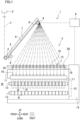
- FIG. 1 is a side view of the spun yarn take-up machine 1.
- the near side on the sheet of FIG. 1 corresponds to the right side.
- the spun yarn take-up machine 1 is configured to simultaneously form packages P by taking up plural (e.g., 32 in the present embodiment) yarns Y spun out from a spinning apparatus 2 and winding the yarns Y onto bobbins B.
- the spun yarn take-up machine 1 of the present embodiment is, for example, arranged to wind 32 yarns spun out from the spinning apparatus 2 by using a pair of winding devices 5 (described later) each of which winds 16 yarns.
- Each yarn Y is a multi-filament yarn having filaments (not illustrated) .
- Each filament is a synthetic fiber made of, e.g., polyester.
- the spun yarn take-up machine 1 includes, for example, a first godet roller 3, a second godet roller 4, a pair of winding devices 5, a controller 6, a yarn threading member 30 (see FIG. 4 ), and a metal plate member 50 (see FIG. 2 ).
- the first godet roller 3 and the second godet roller 4 are arranged to take up yarns Y and feed them to the downstream side in the yarn running direction.
- the first godet roller 3 and the second godet roller 4 are supported by a long supporting body 7 that extends obliquely rearward and upward from a location above front end portions of the pair of winding devices 5. It is noted that FIG. 1 shows one of the paired winding devices 5. Furthermore, the yarn threading member 30 is not shown in FIG. 1 .
- the first godet roller 3 is a roller having a rotational axis substantially in parallel to the left-right direction.
- the first godet roller 3 is attached to a front end portion of the supporting body 7.
- the first godet roller 3 is rotationally driven by an unillustrated motor.
- the yarns Y spun out from the spinning apparatus 2 are sent to the second godet roller 4 while being aligned in the left-right direction and wound onto the first godet roller 3.
- the second godet roller 4 is a roller having a rotational axis substantially in parallel to the left-right direction.
- the second godet roller 4 is provided above and rearward of the first godet roller 3.
- the second godet roller 4 is rotationally driven by an unillustrated motor.
- the second godet roller 4 is provided obliquely rearward of and above the first godet roller 3 and is attached to the supporting body 7.
- the second godet roller 4 is arranged to be movable along the extending direction of the supporting body 7.
- the second godet roller 4 is, for example, movable by a roller movement mechanism 9 including an unillustrated motor, pulleys, and an endless belt, between a front position indicated by two-dot chain lines in FIG.
- the front position is forward of and below the rear position, and is closer to the first godet roller 3 than the rear position is to the first godet roller 3.
- the front position is a position where yarn threading onto the second godet roller 4 is performed.
- the rear position is a position where a winding operation of winding a yarn Y onto a bobbin B attached to a bobbin holder 13 is performed.
- the rear position is also a position where yarn threading to later-described fulcrum guides 20 is performed.
- Each of the yarns Y is sent from the first godet roller 3 to the second godet roller 4, and then sent to one of the paired winding devices 5.
- a half of the yarns Y is sent to one winding device 5 and the remaining half of the yarns Y is sent to the other winding device 5.
- a yarn path of the yarns Y running from the first godet roller 3 to the second godet roller 4 extends obliquely rearward and upward.
- a regulatory guide 8 is provided between the first godet roller 3 and the second godet roller 4.
- the regulatory guide 8 holds the yarns Y to be aligned in the left-right direction at predetermined intervals in the left-right direction.
- Each of the paired winding devices 5 is configured to simultaneously form packages P by winding the yarns Y onto the bobbins B.
- the paired winding devices 5 are provided below the first godet roller 3 and the second godet roller 4.
- the paired winding devices 5 are disposed to be symmetric in the left-right direction (i.e., plane-symmetric).
- the winding device 5 on the left side and the winding device 5 on the right side are provided on the respective sides of the second godet roller 4 in the left-right direction and are arranged to oppose each other over a yarn path of the yarns Y sent from the second godet roller 4.
- Each of the paired winding devices 5 is configured to wind a half (e.g., 16 in the present embodiment) of the yarns sent from the second godet roller 4.
- the controller 6 is, for example, a typical computer device and is configured to control the entire spun yarn take-up machine 1.
- the controller 6 is electrically connected to sections of the spun yarn take-up machine 1 and controls the sections based on a predetermined program.
- the controller 6 includes an unillustrated input unit to which an input from an operator can be made.
- FIG. 2 is a front view of the winding device 5.
- the near side on the sheet of FIG. 2 corresponds to the front side.
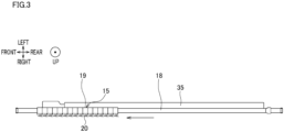
- FIG. 3 illustrates the movement of later-described fulcrum guides 20.
- the following will detail the arrangement of the winding device 5 that is the left one among the paired winding devices 5.
- the winding devices 5 are arranged to be symmetric in the left-right direction. Because the right winding device 5 is structurally identical with the left winding device 5, the right winding device 5 will not be explained.
- the winding device 5 includes a supporting frame 11, a turret 12, and two bobbin holders 13.
- the supporting frame 11 is a member extending in the front-rear direction.
- the supporting frame 11 is cantilevered by a standing base 14 and protrudes forward (see FIG. 1 ).
- the turret 12 is a disc-shaped member having a rotational axis substantially in parallel to the front-rear direction.
- the turret 12 is supported by the base 14 to be rotatable.
- the turret 12 is rotationally driven by an unillustrated turret motor.
- Each of the two bobbin holders 13 are rotatably supported by the turret 12 and protrude forward from the front surface of the turret 12.
- the rotational axis direction of each bobbin holder 13 is substantially in parallel to the front-rear direction.
- the two bobbin holders 13 When viewed in the front-rear direction, the two bobbin holders 13 are point-symmetric about the center of the turret 12 (see FIG. 1 ). To each bobbin holder 13, the bobbins B provided for the respective yarns Y are attached to be lined up in the front-rear direction. The bobbins B are rotatably supported by each of the two bobbin holders 13. Each of the two bobbin holders 13 is independently rotated and driven by an unillustrated winding motor.
- Each winding device 5 includes guide units 15, traverse guides 16, and a contact roller 17.
- a guide supporter 18 is provided above the supporting frame 11, to extend in the front-rear direction (see FIG. 1 ).
- the guide units 15 are attached to the guide supporter 18 and are arranged to be movable in the front-rear direction.
- the guide units 15 are provided to correspond to the respective bobbins B and are aligned along the front-rear direction.
- Each of the guide units 15 includes a main body 19 and a fulcrum guide 20.
- the main body 19 is movably attached to the guide supporter 18.
- the fulcrum guide 20 is fixed to the main body 19 and functions as a fulcrum of the traversal of the yarn Y traversed by each traverse guide 16.
- the guide units 15 are arranged to be movable between distanced positions (see FIG. 1 ) where the yarns Y are wound onto the bobbins B and gathered positions (see FIG. 3 ) where the guide units 15 are close to one another in the front-rear direction as compared to the distanced positions.
- guide units 15 neighboring to each other in the front-rear direction are connected with each other by an unillustrated belt.
- the rearmost guide unit 15 is movable in the front-rear direction by, for example, an unillustrated linear slider.
- the guide units 15 are movable between the distanced positions where the units are distanced from one another and gathered positions where the units are gathered on the front side as compared to the distanced positions. As described below, yarn threading to the fulcrum guides 20 is performed when the fulcrum guides 20 are at the gathered positions.
- the traverse guides 16 are aligned in the front-rear direction. Each of the traverse guides 16 is configured to traverse a corresponding yarn Y in the front-rear direction by being driven by, e.g., an unillustrated traverse motor.
- the contact roller 17 is a roller having a rotational axis substantially in parallel to the front-rear direction, and is provided immediately above the upper bobbin holder 13. The contact roller 17 is configured to make contact with the surfaces of the packages P supported by the upper bobbin holder 13. With this, the contact roller 25 applies a contact pressure to the surfaces of the packages P, to adjust the shape of each package P.
- the yarns Y traversed by the traverse guides 16 are wound onto the bobbins B, with the result that the packages P are formed.
- the turret 12 is rotated to switch over the upper and lower positions of the two bobbin holders 13.
- the bobbin holder 13 having been at the lower position is moved to the upper position, which allows the yarns Y to be wound onto the bobbins B attached to the bobbin holder 13 having been moved to the upper position, to form packages P again.
- the bobbin holder 13 to which the fully-formed packages P are attached is moved to the lower position.
- the fully-formed packages P are then collected by, e.g., an unillustrated package collector.
- the yarn threading member 30 is used for threading the yarns Y to the fulcrum guides 20. As shown in FIG. 2 , the yarn threading member 30 is provided on the downstream side of the fulcrum guides 20 in the yarn running direction. The yarn threading member 30 is provided to correspond to each winding device 5. Therefore, a pair of yarn threading members 30 are provided in the present embodiment.
- the paired yarn threading members 30 are substantially symmetric in the left-right direction and are structurally identical with each other. The following will detail the arrangement of the yarn threading member 30 corresponding to the winding device 5 that is the left one among the paired winding devices 5, and the yarn threading member 30 corresponding to the winding device 5 that is the right one will not be described.
- the yarn threading member 30 is a flat plate member that is more or less comb-shaped. As shown in FIG. 4 , the yarn threading member 30 has retaining grooves 31 in which the yarns Y are retained, respectively.
- the retaining grooves 31 are aligned at least in the left-right direction.
- the retaining grooves 31 are aligned in a direction in parallel to the extending direction of a later-described yarn contact portion 51.
- the inlet of each retaining groove 31 is formed at a rear portion of the yarn threading member 30.
- the pitch of the retaining grooves 31 is substantially identical with the pitch in the left-right direction of the yarns Y, which is defined by the regulatory guide 8.
- the pitch of the retaining grooves 31 indicates the distance between the centers of neighboring retaining grooves 31.
- the yarn threading member 30 retains the yarns Y to be separated from one another, as the yarns Y are threaded into the respective retaining grooves 31.
- the pitch of the inlets of the retaining grooves 31 is substantially identical with the pitch of the bottom portions of the grooves.
- the yarn threading member 30 may be arranged such that the pitch of the bottom portions of the retaining grooves 31 is wider than the pitch of the inlets of the grooves.
- the pitch of the bottom portions of the retaining grooves 31 is arranged to be wider than the pitch of the inlets of the grooves. Because the pitch of the yarns threaded to the yarn threading member 30 is wide, yarn threading from the yarn threading member 30 to the fulcrum guides 20 can be easily done. In this case, the pitch of the inlets of the retaining grooves 31 is substantially identical with the pitch in the left-right direction of the yarns Y, which is defined by the regulatory guide 8.
- the yarn threading member 30 is attached to the winding device 5 through a driving mechanism 40.
- a supporting member 35 (see FIG. 3 and FIG. 5 ) which is positionally fixed is provided between the supporting frame 11 and the guide supporter 18 of the winding device 5 in the up-down direction.
- the supporting member 35 is, for example, a member extending in the front-rear direction.
- the driving mechanism 40 is attached to the supporting member 35 of the winding device 5.
- the yarn threading member 30 is attached to the driving mechanism 40 through a substantially L-shaped interposed member (see FIG. 5 ). In other words, the yarn threading member 30 is attached to the supporting member 35 of the winding device 5 through the driving mechanism 40.
- the spun yarn take-up machine 1 of the present embodiment further includes the driving mechanism 40 which is configured to move the yarn threading member 30.
- the driving mechanism 40 is provided to correspond to each winding device 5. Therefore, a pair of driving mechanisms 40 are provided in the present embodiment.
- the paired driving mechanisms 40 are substantially symmetric in the left-right direction and are structurally identical with each other. The following will detail the arrangement of the driving mechanism 40 corresponding to the winding device 5 that is the left one among the paired winding devices 5, and the driving mechanism 40 corresponding to the winding device 5 that is the right one will not be described.
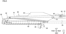
- the driving mechanism 40 moves the yarn threading member 30 between a yarn threading start position where yarn threading to the fulcrum guides 20 starts and a yarn threading completion position where yarn threading to the fulcrum guides 20 is completed.
- the yarn threading start position is in the vicinity of the rearmost fulcrum guide 20 among the fulcrum guides 20 at the gathered positions (see two-dot chain lines in FIG. 5 ).
- the yarn threading completion position is forward of the frontmost fulcrum guide 20 among the fulcrum guides 20 (see solid lines in FIG. 5 ). In the left-right direction, the yarn threading start position is to the right of the yarn threading completion position.
- the yarn threading member 30 at the yarn threading start position moves obliquely leftward and forward to reach the yarn threading completion position.
- the driving mechanism 40 is attached to the supporting member 35 of the winding device 5.
- the driving mechanism 40 includes a support arm 61, a guide rail 62, a swing arm 63, a linear slider 64, and an air cylinder (not illustrated).
- the support arm 61 to which the yarn threading member 30 is attached through the interposed member 42 moves at least in the front-rear direction along the guide rail 62, in response to an action of the linear slider 64.
- the guide rail 62 is able switch the direction of the movement of the support arm 61 and the yarn threading member 30 by swinging together with the swing arm 63 in response to an action of the air cylinder (not illustrated).
- the support arm 61 is a long member extending at least in the front-rear direction. At a front end portion of the support arm 61, the yarn threading member 30 is fixed through the interposed member 42.
- the guide rail 62 is a substantially linear rail extending at least in the front-rear direction. The guide rail 62 is disposed to guide the support arm 61 at least in the front-rear direction.
- the swing arm 63 is, for example, a plate-shaped arm extending at least in the front-rear direction. As shown in FIG. 5 , for example, the swing arm 63 is provided at a front portion of the driving mechanism 40. A rear end portion of the swing arm 63 is connected to the supporting member 35 through a swing shaft 75 having an axis extending in the up-down direction. The swing arm 63 is therefore able to swing together with the guide rail 62. As the swing arm 63 swings about the swing shaft 75, the direction in which the guide rail 62 extends is changed. Due to this, the direction in which the support arm 61 and the yarn threading member 30 move is changed.
- the linear slider 64 is a device configured to move the support arm 61 in the front-rear direction.
- the linear slider 64 is, for example, a known rodless cylinder that is driven by compressed air.
- the linear slider 64 includes a cylinder main body 81 and a slider 82.
- the cylinder main body 81 extends in the front-rear direction.
- the cylinder main body 81 is fixed to a rear portion of the supporting member 35 by means of, for example, an unillustrated fastener.
- the cylinder main body 81 is integrated with the supporting member 35.
- the cylinder main body 81 may be welded to the supporting member 35, for example.
- the slider 82 is arranged to be slidable in the front-rear direction along the cylinder main body 81.
- the support arm 61 is swingably attached to the slider 82.
- the slider 82 is movable between a position in the vicinity of the front end portion and a position in the vicinity of the rear end portion of the cylinder main body 81.
- the unillustrated air cylinder is configured to swing the swing arm 63 and the guide rail 62.
- another cylinder mechanism driven by fluid or a motor-driven driving mechanism e.g., a ball screw mechanism or a rack-and-pinion mechanism
- a motor-driven driving mechanism e.g., a ball screw mechanism or a rack-and-pinion mechanism
- yarn threading from the yarn threading member 30 to the fulcrum guides 20 is performed.
- yarn threading to the fulcrum guides 20 by the yarn threading member 30 is performed from the rear side to the front side in the front-rear direction.
- the rear side in the front-rear direction is equivalent to one side in the arrangement direction in the present invention.
- the front side in the front-rear direction is equivalent to the other side in the arrangement direction in the present invention.
- a suction gun 80 (sucking holding member of the present invention; see FIG. 7 ) which is configured to suck plural yarns Y together is used when the yarns Y spun out from the spinning apparatus 2 are threaded to the fulcrum guides 20.
- the yarns Y that are sucked together by the suction gun 80 are threaded to the retaining grooves 31 of the yarn threading member 30. Thereafter, while the yarns Y are maintained to be sucked by the suction gun 80, the yarn threading member 30 is moved by the driving mechanism 40 so that the yarn threading from the yarn threading member 30 to the fulcrum guides is performed.
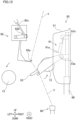
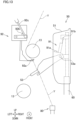
- the spun yarn take-up machine 1 of the present embodiment includes the yarn contact portion 51.
- the metal plate member 50 including the yarn contact portion 51 with reference to FIG. 2 , FIG. 6 , and FIG. 7 .
- the metal plate member 50 is provided to correspond to each winding device 5. Therefore, a pair of metal plate members 50 are provided in the present embodiment.
- the paired metal plate members 50 are substantially symmetric in the left-right direction and are structurally identical with each other. The following will detail the arrangement of the metal plate member 50 corresponding to the winding device 5 that is the left one among the paired winding devices 5, and the metal plate member 50 corresponding to the winding device 5 that is the right one will not be described.
- the metal plate member 50 is provided at a right portion of the winding device 5.
- the metal plate member 50 is placed on the floor surface through a leg portion 60. Behind the metal plate member 50, the leg portion 60 extends to reach the vicinity of the upper end of the metal plate member 50 (see FIG. 6 ).
- the metal plate member 50 is a plate member which extends in the left-right direction and in the up-down direction. When viewed in the front-rear direction, the metal plate member 50 is more or less trapezoidal in shape. When viewed in the front-rear direction, the upper left corner and the lower left corner of the metal plate member 50 are rounded.
- the top surface of the metal plate member 50 is positioned below the fulcrum guide 20.
- the top surface of the metal plate member 50 may be positioned above the fulcrum guide 20.
- the yarn contact portion 51 capable of making contact with the yarns Y is formed on the top surface of the metal plate member 50.
- the top surface of the metal plate member 50 is tilted so that the left end is below the right end.
- the extending direction of the yarn contact portion 51 is an obliquely rightward and upward direction.
- the yarn contact portion 51 is tilted so that an end portion on the left side (one side) in the extending direction is below an end portion on the right side (the other side).
- the left-right direction when viewed in the up-down direction, the left-right direction is in parallel to the extending direction.
- the extending direction is tilted relative to the left-right direction.
- a non-limiting example of the tilt of the extending direction relative to the left-right direction when viewed in the front-rear direction is 10 degrees.
- the metal plate member 50 is provided at a position where the yarn contact portion 51 is able to make contact with the yarns Y running between the yarn threading member 30 and the suction gun 80.
- the metal plate member 50 is provided forward of the frontmost fulcrum guide 20 in the front-rear direction.
- the yarn contact portion 51 is provided forward of the frontmost fulcrum guide 20 in the front-rear direction.
- the yarn contact portion 51 is shaped so that the yarns Y are able to make contact with the yarn contact portion 51 while yarn threading from the yarn threading member 30 to the fulcrum guides 20 is being performed. This arrangement will be detailed as below.
- the yarns Y in contact with the yarn contact portion 51 moves obliquely leftward and downward toward the left end portion of the yarn contact portion 51, in accordance with the yarn threading from the yarn threading member 30 to the fulcrum guides 20.
- the length in the extending direction of the yarn contact portion 51 is sufficient for preventing the yarns Y moving in accordance with the yarn threading from dropping off from the left end portion of the yarn contact portion 51, while the yarn threading from the yarn threading member 30 to the fulcrum guides 20 is being performed.
- the metal plate member 50 is to the right of the bobbin holder 13 in the left-right direction.
- the bobbin holder 13 is to the left of (i.e., on one side of) the yarn contact portion 51 in the left-right direction (or the extending direction).
- the bobbin holder 13 at the winding position where the yarns Y are wound onto the bobbins B to form the packages P is to the left of (on one side of) the yarn contact portion 51 in the left-right direction (or the extending direction).
- the yarn contact portion 51 is preferably a contact surface with which the yarns Y are able to make surface-contact.
- the yarn contact portion 51 has a contact surface that is rounded when viewed in the left-right direction.
- a drop prevention portion 52 is formed to prevent the yarns Y from dropping off from the right end portion of the yarn contact portion 51 on the other side in the left-right direction (or the extending direction).
- the drop prevention portion 52 is a protruding portion formed at a right end portion of the top surface of the metal plate member 50. The upper end of the drop prevention portion 52 is above the right end portion of the yarn contact portion 51.
- a lambda guide 53 (wind guide of the present invention) is attached to the leg portion 60.
- the lambda guide 53 is a guide for guiding the yarns Y threaded to the fulcrum guides 20 by the yarn threading member 30 to wind positions where the yarns Y are wound onto the bobbins B attached to the bobbin holder 13 at the winding position.
- the lambda guide 53 is provided below the yarn contact portion 51.
- the lambda guide 53 is movable between a standby position (see FIG. 6 ) and a swing position (see FIG. 11 ). To be more specific, for example, the lambda guide 53 is movable from the standby position to the swing position (see a solid arrow in FIG.
- the lambda guide 53 is driven by an unillustrated air cylinder to swing leftward about a rotational shaft 53a extending in the front-rear direction.
- the yarns Y are threaded to a later-described first separator 91.
- the yarns Y threaded to the first separator 91 are captured by a second separator 92 (described later), and are then guided to wind positions that are set for the respective bobbins B.
- the process of guiding from the lambda guide 53 to the wind positions through the first separator 91 and the second separator 92 will be detailed later.
- the metal plate member 50 is provided with the yarn contact portion 51 and the drop prevention portion 52.
- the lambda guide 53 is attached to the leg portion 60.
- the metal plate member 50 is connected to the leg portion 60.
- the yarn contact portion 51, the drop prevention portion 52, and the lambda guide 53 are integrally formed.
- a guide portion 54 is formed on the left side surface of the metal plate member 50.
- the guide portion 54 is provided to guide the yarns Y from the yarn contact portion 51 to the lambda guide 53.
- the guide portion 54 extends along the up-down direction.
- the guide portion 54 is a side surface of the metal plate member 50 extending from the left end portion of the yarn contact portion 51 to the lambda guide 53.
- the spun yarn take-up machine 1 of the present embodiment includes the first separator 91 and the second separator 92.
- the following will detail the first separator 91 and the second separator 92 corresponding to the winding device 5 that is the left one among the paired winding devices 5, and the first separator 91 and the second separator 92 corresponding to the winding device 5 that is the right one will not be described.
- FIG. 1 and FIG. 2 do not show the first separator 91 and the second separator 92.
- members such as the turret 12 are omitted in FIG. 9 for the sake of simplicity.
- the first separator 91 is configured to temporarily hold the yarns Y threaded to the lambda guide 53 and then hand over the yarns to the second separator 92.
- the first separator 91 is, for example, attached to the leg portion 60.
- the first separator 91 may be attached to a member different from the leg portion 60.
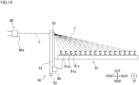
- the first separator 91 includes plural first separator guides 91a and a rotational shaft 91b.
- the first separator guides 91a are aligned along the front-rear direction (see FIG. 10 ).
- the first separator guides 91a are movable between distanced positions where the yarns Y are wound onto the bobbins B and gathered positions (see FIG. 10 ) where the guides are close to one another in the front-rear direction as compared to the distanced positions.
- the first separator guides 91a are, for example, movable between the distanced positions and the gathered positions by an unillustrated linear slider.
- the pitch in the front-rear direction of the neighboring first separator guides 91a at the distanced positions is substantially identical with the pitch in the front-rear direction of the neighboring fulcrum guides 20 at the distanced positions.
- the pitch in the front-rear direction of the neighboring first separator guides 91a indicates the distance in the front-rear direction between contact points of the neighboring first separator guides 91a.
- the contact point is a point where the first separator guide 91a makes contact with the yarn Y.
- the pitch in the front-rear direction of the neighboring fulcrum guides 20 indicates the distance in the front-rear direction between contact points of the neighboring fulcrum guides 20.
- the contact point is a point where the fulcrum guide 20 makes contact with the yarn Y.
- Each first separator guide 91a is a guide to which the yarns Y threaded to the lambda guide 53 at the swing position are threaded, on the upstream in the yarn running direction of the lambda guide 53 and on the downstream in the yarn running direction of each fulcrum guide 20.
- Each first separator guide 91a is, for example, a plate member having a surface substantially in parallel to the horizontal plane.
- Each first separator guide 91a is concave in shape and is open rearward.
- the rotational shaft 91b extends in the front-rear direction.
- the first separator 91 is swingable between a standby position (see FIG. 9 ) and a handover position (see FIG. 11 ) by rotating about the rotational shaft 91b.
- the first separator 91 for example, swings by being driven by an unillustrated air cylinder.
- the second separator 92 is configured to move the yarns Y handed over from the first separator 91 to the wind position where the yarns Y are wound onto the bobbins B.
- the second separator 92 is, for example, attached to the base 14.
- the second separator 92 may be attached to a member different from the base 14.
- the second separator 92 includes plural second separator guides 92a, a rotational shaft 92b, and a driving mechanism 92c.
- the second separator guides 92a are aligned along the front-rear direction (not illustrated).
- the pitch in the front-rear direction of the neighboring second separator guides 92a is substantially identical with the pitch in the front-rear direction of the neighboring first separator guides 91a.
- the pitch in the front-rear direction of the neighboring second separator guides 92a indicates the distance in the front-rear direction between contact points of the neighboring second separator guides 92a.
- the contact point is a point where the second separator guide 92a makes contact with the yarn Y.
- Each second separator guide 92a is, for example, a plate member having a surface intersecting with the horizontal plane.
- Each second separator guide 92a is concave in shape and is open rearward.
- the rotational shaft 92b extends in the front-rear direction.
- the second separator 92 is swingable between a standby position (see FIG. 9 ), a handover position (see FIG. 11 ), and a yarn winding position (see FIG. 13 ) by rotating about the rotational shaft 92b.
- the second separator guide 92a swings by being driven by the driving mechanism 92c.
- the driving mechanism 92c includes, for example, an air cylinder and a piston.
- the working space W in which the operator performs the yarn threading to the fulcrum guides 20 by handling the suction gun 80 is forward of the bobbin holder 13 in the front-rear direction (see FIG. 1 ).
- the working space W is on the front side or the rear side in the front-rear direction of the bobbin holder 13, which side is close to the yarn contact portion 51 in the front-rear direction.
- the controller 6 moves the fulcrum guides 20 to the gathered positions (see FIG. 3 ).
- the driving mechanism 40 moves the yarn threading member 30 to the yarn threading position (not illustrated) that is forward of the frontmost fulcrum guide 20 and is to the right of the fulcrum guides 20.
- the operator then operates the suction gun 80 to thread the yarns Y, which are threaded on the second godet roller 4 at the rear position, to the respective retaining grooves 31 of the yarn threading member 30 at the yarn threading position.
- the driving mechanism 40 moves the yarn threading member 30 to the yarn threading start position (indicated by two-dot chain lines in FIG. 5 ).
- the operator moves the suction gun 80 to a position that is forward of the metal plate member 50 and below the yarn contact portion 51, so as to cause the yarns Y sucked and held by the suction gun 80 to make contact with the yarn contact portion 51.
- the yarns Y preferably make contact with a part of the yarn contact portion 51, which is to the right of a substantially central part of the yarn contact portion 51.
- the driving mechanism 40 moves the yarn threading member 30 from the yarn threading start position to the yarn threading completion position (see solid lines in FIG. 5 ) .
- the handover of the yarns Y from the yarn threading member 30 to the fulcrum guides 20 is completed.
- the yarn threading to the fulcrum guides 20 is completed.
- the operator After the completion of the handover of the yarns Y from the yarn threading member 30 to the fulcrum guides 20, the operator operates the suction gun 80 to separate the yarns Y from the yarn contact portion 51. To be more specific, the operator moves the suction gun 80, which is at the position forward of the metal plate member 50 and below the yarn contact portion 51, further leftward, so as to separate the yarns Y from the left end portion of the yarn contact portion 51.
- the operator stops the leftward movement in the left-right direction of the suction gun 80. Almost at the same time as the stop of the movement in the left-right direction of the suction gun 80, the operator moves the suction gun 80 downward so as to move the yarns Y downward along the guide portion 54 formed on the left side surface of the metal plate member 50.
- the operator is able to separate the yarns Y from the yarn contact portion 51 and move them to a low position simply by moving the suction gun 80 downward in the up-down direction.
- the suction gun 80 is moved downward, the yarns Y slide down along the inclination of the yarn contact portion 51, and are then guided to a low position where the lambda guide 53 is provided, along the guide portion 54 on the left side surface of the metal plate member 50.
- the metal plate members 50 in each of which the yarn contact portion 51 formed at the top surface is tilted are provided to be symmetric in the left-right direction.
- the operator threads the yarns Y, which have been moved downward along the guide portion 54 on the left side surface of the metal plate member 50, to the lambda guide 53 attached to a lower portion of the metal plate member 50.
- the yarns Y are threaded to the first separator 91.
- the controller 6 swings the lambda guide 53 by driving the unillustrated swing mechanism and guides the yarns Y to the respective wind positions by suitably swinging the first separator 91 and the second separator 92.
- the yarns Y are therefore wound onto the respective bobbins B attached to the bobbin holder 13, and the subsequent winding operation is performed.
- the first separator guides 91a are, for example, moved to the gathered positions in advance before the yarn threading to the fulcrum guide 20.
- the controller 6 moves the second separator 92 to a predetermined position between the standby position and the handover position by driving the driving mechanism 92c (see FIG. 12 ).
- the controller 6 moves the second separator 92 to a position which is between the standby position and the yarn winding position and is in the vicinity of the rotation center of the turret 12 (see FIG. 12 ).
- the controller 6 moves the bobbin holder 13 to which bobbins B with no yarns Y thereon are attached, to the winding position (see solid arrows in FIG. 12 ).
- the second separator 92 is at the above-described predetermined position and the lambda guide 53 is at the swing position.
- the yarns Y running between the second separator 92 and the lambda guide 53 are at around the rotation center of the turret 12, i.e., at around the center of the orbit of the two bobbin holders 13. This arrangement makes it possible to avoid the rotating bobbin holder 13 from making contact with the yarns Y.
- the controller 6 moves the second separator 92 to the yarn winding position by driving the driving mechanism 92c (see FIG. 13 ).
- the unillustrated stopper provided for the bobbin holder 13 prevents the bobbin holder 13 from moving beyond the yarn winding position. Consequently, the yarns Y threaded to the second separator guides 92a are guided to the respective wind positions corresponding to the bobbins B. Each yarn Y guided to each wind position is wound onto each bobbin B.
- each yarn Y having been guided to the wind position is threaded to the hook. In this way, each yarn Y is wound onto each bobbin B.
- the spun yarn take-up machine 1 of the present embodiment as the yarn threading member 30 is moved relative to the fulcrum guides 20 while the yarns Y sucked and held by the suction gun 80 are retained by the yarn threading member 30, yarn threading to the fulcrum guides 20 is performed, and the spun yarn take-up machine 1 includes the yarn contact portion 51 which is positioned to be able to make contact with the yarns Y running between the yarn threading member 30 and the suction gun 80.
- the yarn threading to the fulcrum guides 20 is performed from the rear side (one side) to the front side (the other side) in the front-rear direction (arrangement direction), and the yarn contact portion 51 is on the other side of the frontmost fulcrum guide 20 (which is on the other side of the remaining fulcrum guides 20) in the front-rear direction (arrangement direction). If the yarn threading member 30 moves beyond the yarn contact portion 51 in the front-rear direction (arrangement direction) while yarn threading to the fulcrum guides 20 is being performed, the yarns Y may be detached from the yarn contact portion 51, depending on the positional relationship between the yarn contact portion 51 and the suction gun 80.
- the layout of the suction gun 80 may be restricted by the existence of, for example, another member.
- the yarn threading member 30 does not move beyond the yarn contact portion 51 in the front-rear direction (arrangement direction) while yarn threading to the fulcrum guides 20 is being performed. It is therefore possible to avoid detachment of the yarns Y from the yarn contact portion 51 while yarn threading to the fulcrum guides 20 is being performed.
- the yarn contact portion 51 extends in the extending direction. This facilitates the yarns Y to make contact with the yarn contact portion 51 extending in the extending direction. Furthermore, in the present embodiment, the yarn contact portion 51 is tilted so that an end portion on the left side (one side) in the extending direction is below an end portion on the right side (the other side). After the completion of the handover of the yarns Y from the yarn threading member 30 to the fulcrum guides 20, the yarns Y are separated from the yarn contact portion 51 in order to proceed to the step of winding the yarns onto the bobbins B attached to the bobbin holder 13.
- the yarns Y slide on the yarn contact portion 51 by gravity, along the direction that is in parallel to the extending direction and is from the end portion on the right side (the other side) toward the end portion on the left side (one side) of the yarn contact portion 51.
- the force required for moving the yarns Y is reduced and the yarns Y are smoothly separated from the yarn contact portion 51.
- the bobbin holder 13 is to the left of (on one side of) the yarn contact portion 51 in the left-right direction (the extending direction of the yarn contact portion 51).
- the yarns Y are at locations close to the bobbin holder 13 as compared to the yarn contact portion 51. It is therefore possible to directly move the yarns Y separated from the yarn contact portion 51 to the position where the bobbin holder 13 is provided, without allowing the yarns Y to move beyond the yarn contact portion 51 in the left-right direction. Due to this, after the completion of the handover of the yarns Y from the yarn threading member 30 to the fulcrum guides 20, it is possible to smoothly proceed to the step of winding each yarn Y onto the bobbin B attached to the bobbin holder 13.
- the yarns Y move toward the left end portion (on one side) of the yarn contact portion 51 in the extending direction, while being in contact with the yarn contact portion 51.
- the spun yarn take-up machine 1 of the present embodiment includes the drop prevention portion 52 configured to prevent the yarns Y from dropping off from the right end portion of the yarn contact portion 51 in the extending direction. In the present embodiment, it is possible to prevent the yarns Y in contact with the yarn contact portion 51 from unintentionally dropping off from the right end portion of the yarn contact portion 51.
- the yarn contact portion 51 is shaped so that the yarns Y are able to make contact with the yarn contact portion 51 while yarn threading from the yarn threading member 30 to the fulcrum guides 20 is being performed.
- yarn shaking is reliably suppressed when the yarns Y held by the yarn threading member 30 are handed over to the fulcrum guides 20. The yarn threading from the yarn threading member 30 to the fulcrum guides 20 is therefore further properly done.
- the yarn contact portion 51 is a contact surface with which the yarns Y are able to make surface-contact.
- the contact area between each yarn Y and the yarn contact portion 51 is large.
- the load on the yarns Y is small. This suppresses yarn breakage or deflection of the yarns Y due to the contact between the yarns Y and the yarn contact portion 51.
- the lambda guide 53 (wind guide) is provided for guiding the yarns Y threaded to the fulcrum guides 20 to the wind positions where the yarns Y are wound onto the bobbins B attached to the bobbin holder 13.
- the yarn contact portion 51 is integrally formed with the lambda guide 53. According to the present embodiment, after the completion of the handover of the yarns Y from the yarn threading member 30 to each fulcrum guide 20, the yarns Y separated from the yarn contact portion 51 are directly threaded to the lambda guide 53 that is integrally formed with the yarn contact portion 51. Due to this, it is possible to smoothly proceed to the step of winding each yarn Y onto the bobbin B attached to the bobbin holder 13.
- the lambda guide 53 is provided below the yarn contact portion 51.
- the spun yarn take-up machine 1 of the present embodiment further includes the guide portion 54 which extends along the up-down direction and is provided for guiding the yarns Y from the yarn contact portion 51 to the lambda guide 53. Thanks to the guide portion 54, the yarns Y separated from the yarn contact portion 51 are smoothly guided to the lambda guide 53. Due to this, after the completion of the handover of the yarns Y from the yarn threading member 30 to the fulcrum guides 20, it is possible to smoothly proceed to the step of winding each yarn Y onto the bobbin B attached to the bobbin holder 13.
- the driving mechanism 40 is provided to move the yarn threading member 30 between a yarn threading start position where yarn threading to the fulcrum guides 20 starts and a yarn threading completion position where yarn threading to the fulcrum guides 20 is completed.
- the yarn threading member 30 is moved by the driving mechanism 40, when yarn shaking of the yarns Y held by the yarn threading member 30 occurs, the position of the yarn Y handed over to the fulcrum guide 20 cannot be adjusted by finely adjusting the position of the yarn threading member 30. Inclusion of the yarn contact portion 51 is quite effective in this arrangement.
- the working space W in which the operator performs the yarn threading to the fulcrum guides 20 by handling the suction gun 80 is either on the front side (the other side) or the rear side (one side) of the bobbin holder 13 in the front-rear direction (arrangement direction), which side is the side close to the yarn contact portion 51 in the front-rear direction (arrangement direction).
- the operator is allowed to perform operations in a wide space around which the bobbin holders 13 and the fulcrum guides 20 are not provided.
- the yarn threading member 30 has the retaining grooves 31 retaining the respective yarns Y, and the retaining grooves 31 are aligned in a direction in parallel to the extending direction. According to the present embodiment, until the yarns Y threaded to the respective retaining grooves 31 of the yarn threading member 30 reach the yarn contact portion 51, the running plane of each yarn Y passing through the yarn path is maintained to be in parallel to the extending direction. To put it differently, the running plane of the yarns Y running between the retaining grooves 31 and the yarn contact portion 51 is not twisted. On this account, the bending angle of the yarn Y in contact with the yarn contact portion 51 is identical between the yarns Y, and hence the yarn quality influenced by the bending angle is identical between the yarns Y.
- the yarn threading member 30 is provided on the downstream side of the fulcrum guides 20 in the yarn running direction.
- the yarns Y sucked by the suction gun 80 are converged at the suction gun 80. That is to say, the pitch of the yarns Y held by the yarn threading member 30 decreases toward the suction gun 80 provided on the downstream side of the yarn threading member 30.
- the yarn threading member 30 is provided on the downstream side of the fulcrum guides 20 in the yarn running direction.
- the yarns Y whose pitch narrows on the downstream side of the yarn threading member 30 to the fulcrum guides 20 are threaded to the fulcrum guides 20. Due to this, as compared to a case where the yarn threading member 30 is provided on the upstream of the fulcrum guides 20, yarn threading to the fulcrum guides 20 can be easily done in the present embodiment.
- the extending direction of the yarn contact portion 51 when viewed in the up-down direction, is in parallel to the left-right direction. Alternatively, when viewed in the up-down direction, the extending direction of the yarn contact portion 51 may intersect with the left-right direction.
- the yarn contact portion 51 is tilted so that an end portion on the left side (one side) in the extending direction is below an end portion on the right side (the other side).
- the yarn contact portion 51 may be curved so that an end portion on the left side (one side) in the extending direction is below an end portion on the right side (the other side). It is noted that the arrangement in which the yarn contact portion 51 is curved does not encompass a case where a portion of the yarn contact portion 51 between the left end portion and the right end portion is concave so that the portion between the end portions is below the end portions.
- the yarn contact portion 51 may extend along the horizontal direction.
- the drop prevention portion 52 prevents the yarns Y from dropping off from the right end portion (on the other side) of the yarn contact portion 51 that is tilted so that the end portion on the left side (one side) in the extending direction is below the end portion on the right side (the other side).
- the drop prevention portion 52 may prevent the yarns Y from dropping off from the right end portion (on the other side) of the yarn contact portion 51 that extends along the horizontal direction. In this case, the yarns Y move toward the left end portion (on one side) of the yarn contact portion 51 in the extending direction, while being in contact with the yarn contact portion 51.
- the drop prevention portion 52 may not be formed.
- the bobbin holder 13 is to the left of (i.e., on one side of) the yarn contact portion 51 in the left-right direction (or the extending direction).
- the bobbin holder 13 may be to the left of (on one side of) the yarn contact portion 51 which is tilted so that, in the left-right direction (or the extending direction), an end portion on the left side (one side) in the extending direction is below an end portion on the right side (the other side).
- the yarn contact portion 51 and the drop prevention portion 52 are formed in the metal plate member 50.
- the yarn contact portion 51 and the drop prevention portion 52 may be members different from the metal plate member 50.
- the yarn contact portion 51 and the lambda guide 53 are integrally formed.
- the yarn contact portion 51 and the lambda guide 53 may not be integrally formed. In short, the yarn contact portion 51 and the lambda guide 53 may be separated from each other.
- the yarn contact portion 51 is formed on the top surface of the metal plate member 50.
- the yarn contact portion 51 has a contact surface that is rounded when viewed in the left-right direction.
- the yarn contact portion may be formed on an upper circumferential surface of a rod member extending in a predetermined extending direction.
- the upper circumferential surface of the rod member that is the yarn contact portion functions as the contact surface with which the yarns Y are able to make surface-contact.
- the yarn contact portion 51 is shaped as described below so that the yarns Y are able to make contact with the yarn contact portion 51 while yarn threading from the yarn threading member 30 to the fulcrum guides 20 is being performed. That is to say, the length in the extending direction of the yarn contact portion 51 is sufficient for preventing the yarns Y moving in accordance with the yarn threading from dropping off from the left end portion of the yarn contact portion 51, while the yarn threading from the yarn threading member 30 to the fulcrum guides 20 is being performed.
- the yarn contact portion 51 may have a shape different from the shape in the embodiment above, so that the yarns Y are able to make contact with the yarn contact portion 51 while yarn threading from the yarn threading member 30 to the fulcrum guides 20 is being performed.
- a second drop prevention portion may be formed to prevent the yarns Y from dropping off from the left end portion of the yarn contact portion 51 in the left-right direction.
- the yarn contact portion 51 is therefore shaped so that the yarns Y are able to make contact with the yarn contact portion 51 while yarn threading from the yarn threading member 30 to the fulcrum guides 20 is being performed.
- the second drop prevention portion is, for example, structurally identical with the drop prevention portion 51 of the embodiment above.
- the second drop prevention portion is preferably provided on the top surface of the metal plate member 50 in a detachable manner. As the second drop prevention portion is detached, the second drop prevention portion does not obstruct the yarns Y that are detached from the yarn contact portion 51 and guided to a location where the lambda guide 53 is provided.
- the yarns Y when the yarns Y are threaded to the yarn threading member 30 at the yarn threading position, the yarns Y are not in contact with the yarn contact portion 51.
- the yarns Y when the yarns Y are threaded to the yarn threading member 30 at the yarn threading position, the yarns Y may be in contact with the yarn contact portion 51. This arrangement makes it possible to suppress yarn shaking when the yarns Y are threaded to the yarn threading member 30.
- the driving mechanism 40 moves the yarn threading member 30.
- an operator may manually move the yarn threading member 30.
- the yarns Y are handed over from the yarn threading member 30 to the fulcrum guides 20.
- the yarns Y may be handed over from the yarn threading member 30 to the fulcrum guides 20.
- the yarn threading to the fulcrum guides 20 is performed from the rear side (one side) to the front side (the other side) in the front-rear direction (arrangement direction).
- the yarn contact portion 51 may not be provided on the front side (the other side) of the frontmost fulcrum guide 20 (which is on the other side of the remaining fulcrum guides 20) in the front-rear direction (arrangement direction).
- the phrase "move the yarn threading member 30 relative to the fulcrum guides 20" encompasses not only a case where the yarn threading member 30 is moved but also a case where the yarn threading member 30 is moved relative to the fulcrum guides 20 by moving the fulcrum guides 20.
- the guide portion 54 extends along the vertical direction.
- the guide portion 54 may extend in a direction tilted relative to the vertical direction.
- the spun yarn take-up machine 1 may not include the guide portion 54.
- the retaining grooves 31 are aligned in a direction in parallel to the extending direction of the yarn contact portion 51. In this regard, the retaining grooves 31 may not be aligned in a direction in parallel to the extending direction of the yarn contact portion 51.
- the spun yarn take-up machine 1 includes a pair of winding devices 5, the disclosure is not limited to this arrangement.
- the spun yarn take-up machine 1 may include only one winding device 5 among the paired winding devices 5.
- the present invention can be applied to not only the spun yarn take-up machine 1 but also various yarn winders arranged to wind yarns Y.
- the yarn threading member 30 is provided on the downstream side of the fulcrum guides 20 in the yarn running direction.
- the yarn threading member 30 may be provided on the upstream side of the fulcrum guides 20 in the yarn running direction.
Landscapes
- Engineering & Computer Science (AREA)
- Mechanical Engineering (AREA)
- Textile Engineering (AREA)
- Guides For Winding Or Rewinding, Or Guides For Filamentary Materials (AREA)
- Spinning Methods And Devices For Manufacturing Artificial Fibers (AREA)
- Replacing, Conveying, And Pick-Finding For Filamentary Materials (AREA)
Abstract
Description
- The present invention relates to a yarn winder.
- Patent Literature 1 (
Japanese Laid-Open Patent Publication No. 2012-188784 Patent Literature 1 further includes a yarn threading member (yarn threading guide of Patent Literature 1) by which the yarns are threaded to the fulcrum guides. The yarn threading member has grooves that are lined up to correspond to the fulcrum guides in number. - When threading the running yarns to the respective fulcrum guides, an operator causes the grooves of the yarn threading member to retain the yarns. Thereafter, the yarn threading member moves in a direction of obliquely traversing the fulcrum guides aligned in the arrangement direction. As a result, the yarns are threaded one by one to the fulcrum guides from the yarn threading member.
- The yarn winder of
Patent Literature 1 employs a suction gun (sucking holding member) which is configured to suck plural yarns together when the yarns spun out from the spinning apparatus are threaded to the fulcrum guides. To be more specific, the yarns that are sucked together by the suction gun are threaded to the grooves of the yarn threading member. Thereafter, while the yarns are maintained to be sucked by the suction gun, the yarn threading member is moved so that the yarn threading from the yarn threading member to the fulcrum guides is performed. - However, if yarn shaking caused by an airflow generated at a suction port of the suction gun sucking the yarns is propagated to the yarns running on the upstream of the yarn threading member in the yarn running direction, problems such as entanglement of neighboring yarns and inability of positioning the yarns retained by the yarn threading member occur. Due to this, transfer of the yarns from the yarn threading member to the fulcrum guides may not be properly performed.
- An object of the present invention is to properly perform yarn threading from a yarn threading member to fulcrum guides.
- A yarn winder of the present invention comprises: a bobbin holder to which bobbins are attached along a predetermined arrangement direction; fulcrum guides which are aligned in the arrangement direction, are provided to correspond to yarns which are to be wound onto the respective bobbins, and function as fulcrums of traversal when the yarns are traversed; and a yarn threading member which are movable while holding the yarns in a separated manner, yarn threading to the fulcrum guides being performed by moving the yarn threading member relative to the fulcrum guides while the yarns sucked and held by a sucking holding member configured to suck and hold yarns are held by the yarn threading member, the yarn winder further comprising a yarn contact portion which is provided at a location where the yarns running between the yarn threading member and the sucking holding member are able to make contact with the yarn contact portion.
- In the present invention, as the yarns sucked by the sucking holding member are made contact with the yarn contact portion at a location between the sucking holding member and the yarn threading member, it is possible to prevent yarn shaking caused by an airflow generated by the sucking holding member from being propagated to the yarn threading member. On this account, yarn shaking is suppressed when the yarns held by the yarn threading member are handed over to the fulcrum guides. It is therefore possible to properly perform yarn threading from the yarn threading member to the fulcrum guides.
- The yarn winder of the present invention is preferably arranged so that the yarn threading to the fulcrum guides is performed from one side to the other side in the arrangement direction, and the yarn contact portion is provided on the other side of a fulcrum guide that is on the other side of the remaining fulcrum guides in the arrangement direction.
- If the yarn threading member moves beyond the yarn contact portion in the arrangement direction while yarn threading to the fulcrum guides is being performed, the yarns may be detached from the yarn contact portion, depending on the positional relationship between the yarn contact portion and the sucking holding member. To avoid this problem, it is necessary to adjust the position of the sucking holding member. However, depending on the structure of the apparatus, the layout of the sucking holding member may be restricted by the existence of, for example, another member. According to the present invention, regardless of the positional relationship between the yarn contact portion and the sucking holding member, the yarn threading member does not move beyond the yarn contact portion in the arrangement direction while yarn threading to the fulcrum guides is being performed. It is therefore possible to avoid detachment of the yarns from the yarn contact portion while yarn threading to the fulcrum guides is being performed.
- The yarn winder of the present invention is preferably arranged such that the yarn contact portion extends in a predetermined extending direction.
- This arrangement of the present invention facilitates the yarns to make contact with the yarn contact portion extending in the extending direction.
- The yarn winder of the present invention is preferably arranged such that the yarn contact portion is tilted or curved so that an end portion of the yarn contact portion on one side in the extending direction is below an end portion on the other side.
- After the completion of the handover of the yarns from the yarn threading member to the fulcrum guides, the yarns are separated from the yarn contact portion in order to proceed to the step of winding the yarns onto the bobbins attached to the bobbin holder. According to the present invention, the yarns slide on the yarn contact portion by gravity, along the direction that is in parallel to the extending direction and is from the end portion on the other side toward the end portion on the one side of the yarn contact portion. With this arrangement, the force required for moving the yarns is reduced and the yarns are smoothly separated from the yarn contact portion.
- The yarn winder of the present invention is preferably arranged so that the bobbin holder is provided on the one side of the yarn contact portion in the extending direction.
- According to the present invention, the bobbin holder is provided on one side of the yarn contact portion in the extending direction. On this account, after the yarns are moved downward along the yarn contact portion and are separated from the yarn contact portion at a location on one side of the yarn contact portion in the extending direction, the yarns are at locations close to the bobbin holder as compared to the yarn contact portion. It is therefore possible to directly move the yarns separated from the yarn contact portion to the position where the bobbin holder is provided, without allowing the yarns to move beyond the yarn contact portion in the extending direction. Due to this, after the completion of the handover of the yarns from the yarn threading member to the fulcrum guides, it is possible to smoothly proceed to the step of winding each yarn onto the bobbin attached to the bobbin holder.
- The yarn winder of the present invention is preferably arranged such that the yarns move toward the end portion of the yarn contact portion on the one side in the extending direction, while being in contact with the yarn contact portion, and a drop prevention portion is provided to prevent the yarns from dropping off from an end portion of the yarn contact portion on the other side in the extending direction.
- In the present invention, it is possible to prevent the yarns in contact with the yarn contact portion from unintentionally dropping off from the end portion of the yarn contact portion on the other side.
- The yarn winder of the present invention is preferably arranged such that the yarn threading member has retaining grooves which retain the yarns, respectively, and the retaining grooves are aligned along a direction in parallel to the extending direction.
- According to the present invention, until the yarns threaded to the respective retaining grooves of the yarn threading member reach the yarn contact portion, the running plane of each yarn passing through the yarn path is maintained to be in parallel to the extending direction. To put it differently, the running plane of the yarns running between the retaining grooves and the yarn contact portion is not twisted. On this account, the bending angle of the yarn in contact with the yarn contact portion is identical between the yarns, and hence the yarn quality influenced by the bending angle is identical between the yarns.
- The yarn winder of the present invention is preferably arranged such that the yarn contact portion is shaped so that the yarns are able to make contact with the yarn contact portion while yarn threading from the yarn threading member to the fulcrum guides is being performed.
- In the present invention, it is possible to keep the yarns to be in contact with the yarn contact portion during the yarn threading from the yarn threading member to each fulcrum guide. That is to say, it is possible to avoid at least one of the yarns from being detached from the yarn contact portion during the yarn threading from the yarn threading member to each fulcrum guide. On this account, yarn shaking is reliably suppressed when the yarns held by the yarn threading member are handed over to the fulcrum guides. The yarn threading from the yarn threading member to the fulcrum guides is therefore further properly done.
- The yarn winder of the present invention is preferably arranged such that the yarn contact portion is a contact surface with which the yarns are able to make surface-contact.
- The larger the contact area between the yarns and the yarn contact portion is, the smaller the load on each yarn from the yarn contact portion is. According to the present invention, because the yarns are in surface-contact with the yarn contact portion, the contact area between each yarn and the yarn contact portion is large. On this account, as compared to a case where the yarns make contact with an edge-shaped yarn contact portion, i.e., a case where the yarns are in point-contact with the yarn contact portion, the load on the yarns is small. This suppresses yarn breakage or deflection of the yarns due to the contact between the yarns and the yarn contact portion.
- Preferably, the yarn winder of the present invention further comprises a wind guide which is provided for guiding the yarns threaded to the fulcrum guides to wind positions where the yarns are wound onto the bobbins attached to the bobbin holder, the yarn contact member and the wind guide being integrally formed.
- According to the present invention, after the completion of the handover of the yarns from the yarn threading member to each fulcrum guide, the yarns separated from the yarn contact portion are directly threaded to the wind guide that is integrally formed with the yarn contact portion. Due to this, it is possible to smoothly proceed to the step of winding each yarn onto the bobbin attached to the bobbin holder.
- The yarn winder of the present invention is preferably arranged such that the wind guide is provided below the yarn contact portion, and a guide portion is provided to extend along a vertical direction and to guide the yarns from the yarn contact portion to the wind guide.
- Thanks to the guide portion, the yarns separated from the yarn contact portion are smoothly guided to the wind guide. Due to this, after the completion of the handover of the yarns from the yarn threading member to the fulcrum guides, it is possible to smoothly proceed to the step of winding each yarn onto the bobbin attached to the bobbin holder.
- Preferably, the yarn winder of the present invention further comprises a driving mechanism which is configured to move the yarn threading member between a yarn threading start position where the yarn threading to the fulcrum guides starts and a yarn threading completion position where the yarn threading to the fulcrum guides is completed.
- In the arrangement in which the yarn threading member is moved by the driving mechanism, when yarn shaking of the yarns held by the yarn threading member occurs, the position of the yarn handed over to the fulcrum guide cannot be adjusted by finely adjusting the position of the yarn threading member. Inclusion of the yarn contact portion of the present invention is quite effective in this arrangement.
- The yarn winder of the present invention is preferably arranged such that a working space in which an operator performs the yarn threading to the fulcrum guides by handling the sucking holding member is on either one side or the other side of the bobbin holder in the arrangement direction, which side is the side close to the yarn contact portion in the arrangement direction.
- In the present invention, the operator is allowed to perform operations in a wide space around which the bobbin holder and the fulcrum guides are not provided.
- The yarn winder of the present invention is preferably arranged such that, in a yarn running direction in which the yarns run, the yarn threading member is provided on the downstream side of the fulcrum guides.
- The yarns sucked by the sucking holding member are converged at the sucking holding member. That is to say, the pitch of the yarns held by the yarn threading member decreases toward the sucking holding member provided on the downstream side of the yarn threading member. In this regard, in the present invention, the yarn threading member is provided on the downstream side of the fulcrum guides in the yarn running direction. On this account, instead of threading the yarns whose pitch narrows on the downstream side of the yarn threading member to the fulcrum guides, the yarns having a uniform pitch are threaded to the fulcrum guides. Due to this, as compared to a case where the yarn threading member is provided on the upstream of the fulcrum guides, yarn threading to the fulcrum guides can be easily done in the present invention.
-
-
FIG. 1 is a side view of a spun yarn take-up machine of an embodiment. -
FIG. 2 is a front view of a winding device. -
FIG. 3 illustrates movement of fulcrum guides. -
FIG. 4 is an enlarged view of a yarn threading member. -
FIG. 5 shows the yarn threading member moving from a yarn threading start position to a yarn placement completion position. -
FIG. 6 is an enlarged front view of a metal plate member. -
FIG. 7 is a top view showing a state in which yarns running between the yarn threading member and a suction gun are in contact with a yarn contact portion. -
FIG. 8 is an enlarged perspective view of the metal plate member when yarns running between the yarn threading member and the suction gun are in contact with the yarn contact portion. -
FIG. 9 is a front view of a first separator and a second separator. -
FIG. 10 is a plan view of the first separator on which yarns are threaded, which is viewed from above. -
FIG. 11 is a front view showing a state in which a yarn is handed over from the first separator to the second separator. -
FIG. 12 is a front view showing a state in which the second separator has been moved to a yarn winding position. -
FIG. 13 is a front view showing a state in which the yarn is wound onto each bobbin from the second separator. -
FIG. 14 is an enlarged view of a yarn threading member of a modification. - The following will describe an embodiment of the present invention. Hereinafter, directions shown in
FIG. 1 andFIG. 2 will be consistently used as an up-down direction, a left-right direction, and a front-rear direction, for convenience of explanation. The up-down direction is a vertical direction in which the gravity acts. The left-right direction is a direction orthogonal to the up-down direction. The front-rear direction (arrangement direction of the present invention) is a direction which is orthogonal to the up-down direction and the left-right direction, and in which bobbins B (described later) are aligned. A direction in which a yarn Y (described later) runs will be referred to as a yarn running direction. - The following will outline a spun yarn take-up machine 1 (i.e., a yarn winder of the present invention) of an embodiment, with reference to
FIG. 1. FIG. 1 is a side view of the spun yarn take-upmachine 1. The near side on the sheet ofFIG. 1 corresponds to the right side. - The spun yarn take-up
machine 1 is configured to simultaneously form packages P by taking up plural (e.g., 32 in the present embodiment) yarns Y spun out from aspinning apparatus 2 and winding the yarns Y onto bobbins B. The spun yarn take-upmachine 1 of the present embodiment is, for example, arranged to wind 32 yarns spun out from thespinning apparatus 2 by using a pair of winding devices 5 (described later) each of which winds 16 yarns. Each yarn Y is a multi-filament yarn having filaments (not illustrated) . Each filament is a synthetic fiber made of, e.g., polyester. - The spun yarn take-up
machine 1 includes, for example, a first godet roller 3, asecond godet roller 4, a pair of windingdevices 5, acontroller 6, a yarn threading member 30 (seeFIG. 4 ), and a metal plate member 50 (seeFIG. 2 ). The first godet roller 3 and thesecond godet roller 4 are arranged to take up yarns Y and feed them to the downstream side in the yarn running direction. The first godet roller 3 and thesecond godet roller 4 are supported by a long supportingbody 7 that extends obliquely rearward and upward from a location above front end portions of the pair of windingdevices 5. It is noted thatFIG. 1 shows one of the paired windingdevices 5. Furthermore, theyarn threading member 30 is not shown inFIG. 1 . - The first godet roller 3 is a roller having a rotational axis substantially in parallel to the left-right direction. The first godet roller 3 is attached to a front end portion of the supporting
body 7. The first godet roller 3 is rotationally driven by an unillustrated motor. The yarns Y spun out from thespinning apparatus 2 are sent to thesecond godet roller 4 while being aligned in the left-right direction and wound onto the first godet roller 3. - The
second godet roller 4 is a roller having a rotational axis substantially in parallel to the left-right direction. Thesecond godet roller 4 is provided above and rearward of the first godet roller 3. Thesecond godet roller 4 is rotationally driven by an unillustrated motor. Thesecond godet roller 4 is provided obliquely rearward of and above the first godet roller 3 and is attached to the supportingbody 7. Thesecond godet roller 4 is arranged to be movable along the extending direction of the supportingbody 7. Thesecond godet roller 4 is, for example, movable by aroller movement mechanism 9 including an unillustrated motor, pulleys, and an endless belt, between a front position indicated by two-dot chain lines inFIG. 1 and a rear position indicated by solid lines. The front position is forward of and below the rear position, and is closer to the first godet roller 3 than the rear position is to the first godet roller 3. The front position is a position where yarn threading onto thesecond godet roller 4 is performed. The rear position is a position where a winding operation of winding a yarn Y onto a bobbin B attached to abobbin holder 13 is performed. The rear position is also a position where yarn threading to later-described fulcrum guides 20 is performed. - Each of the yarns Y is sent from the first godet roller 3 to the
second godet roller 4, and then sent to one of the paired windingdevices 5. A half of the yarns Y is sent to one windingdevice 5 and the remaining half of the yarns Y is sent to the other windingdevice 5. A yarn path of the yarns Y running from the first godet roller 3 to thesecond godet roller 4 extends obliquely rearward and upward. - In the yarn running direction, a
regulatory guide 8 is provided between the first godet roller 3 and thesecond godet roller 4. Theregulatory guide 8 holds the yarns Y to be aligned in the left-right direction at predetermined intervals in the left-right direction. - Each of the paired winding
devices 5 is configured to simultaneously form packages P by winding the yarns Y onto the bobbins B. The paired windingdevices 5 are provided below the first godet roller 3 and thesecond godet roller 4. The paired windingdevices 5 are disposed to be symmetric in the left-right direction (i.e., plane-symmetric). To be more specific, the windingdevice 5 on the left side and the windingdevice 5 on the right side are provided on the respective sides of thesecond godet roller 4 in the left-right direction and are arranged to oppose each other over a yarn path of the yarns Y sent from thesecond godet roller 4. Each of the paired windingdevices 5 is configured to wind a half (e.g., 16 in the present embodiment) of the yarns sent from thesecond godet roller 4. - The
controller 6 is, for example, a typical computer device and is configured to control the entire spun yarn take-upmachine 1. Thecontroller 6 is electrically connected to sections of the spun yarn take-upmachine 1 and controls the sections based on a predetermined program. Thecontroller 6 includes an unillustrated input unit to which an input from an operator can be made. - The following will detail the winding
device 5 with reference toFIG. 1 to FIG. 3 .FIG. 2 is a front view of the windingdevice 5. The near side on the sheet ofFIG. 2 corresponds to the front side.FIG. 3 illustrates the movement of later-described fulcrum guides 20. The following will detail the arrangement of the windingdevice 5 that is the left one among the paired windingdevices 5. As described above, the windingdevices 5 are arranged to be symmetric in the left-right direction. Because theright winding device 5 is structurally identical with the left windingdevice 5, theright winding device 5 will not be explained. As shown inFIG. 2 , the windingdevice 5 includes a supportingframe 11, aturret 12, and twobobbin holders 13. - The supporting
frame 11 is a member extending in the front-rear direction. The supportingframe 11 is cantilevered by a standingbase 14 and protrudes forward (seeFIG. 1 ). Theturret 12 is a disc-shaped member having a rotational axis substantially in parallel to the front-rear direction. Theturret 12 is supported by the base 14 to be rotatable. Theturret 12 is rotationally driven by an unillustrated turret motor. Each of the twobobbin holders 13 are rotatably supported by theturret 12 and protrude forward from the front surface of theturret 12. The rotational axis direction of eachbobbin holder 13 is substantially in parallel to the front-rear direction. When viewed in the front-rear direction, the twobobbin holders 13 are point-symmetric about the center of the turret 12 (seeFIG. 1 ). To eachbobbin holder 13, the bobbins B provided for the respective yarns Y are attached to be lined up in the front-rear direction. The bobbins B are rotatably supported by each of the twobobbin holders 13. Each of the twobobbin holders 13 is independently rotated and driven by an unillustrated winding motor. - Each winding
device 5 includesguide units 15, traverse guides 16, and acontact roller 17. Above the supportingframe 11, aguide supporter 18 is provided to extend in the front-rear direction (seeFIG. 1 ). Theguide units 15 are attached to theguide supporter 18 and are arranged to be movable in the front-rear direction. Theguide units 15 are provided to correspond to the respective bobbins B and are aligned along the front-rear direction. Each of theguide units 15 includes amain body 19 and afulcrum guide 20. Themain body 19 is movably attached to theguide supporter 18. Thefulcrum guide 20 is fixed to themain body 19 and functions as a fulcrum of the traversal of the yarn Y traversed by eachtraverse guide 16. - The guide units 15 (i.e., the fulcrum guides 20) are arranged to be movable between distanced positions (see
FIG. 1 ) where the yarns Y are wound onto the bobbins B and gathered positions (seeFIG. 3 ) where theguide units 15 are close to one another in the front-rear direction as compared to the distanced positions. To be more specific, for example, guideunits 15 neighboring to each other in the front-rear direction are connected with each other by an unillustrated belt. Therearmost guide unit 15 is movable in the front-rear direction by, for example, an unillustrated linear slider. As the linear slider is driven, theguide units 15 are movable between the distanced positions where the units are distanced from one another and gathered positions where the units are gathered on the front side as compared to the distanced positions. As described below, yarn threading to the fulcrum guides 20 is performed when the fulcrum guides 20 are at the gathered positions. - The traverse guides 16 are aligned in the front-rear direction. Each of the traverse guides 16 is configured to traverse a corresponding yarn Y in the front-rear direction by being driven by, e.g., an unillustrated traverse motor. The
contact roller 17 is a roller having a rotational axis substantially in parallel to the front-rear direction, and is provided immediately above theupper bobbin holder 13. Thecontact roller 17 is configured to make contact with the surfaces of the packages P supported by theupper bobbin holder 13. With this, the contact roller 25 applies a contact pressure to the surfaces of the packages P, to adjust the shape of each package P. - In the winding
device 5 structured as described above, when theupper bobbin holder 13 is rotationally driven, the yarns Y traversed by the traverse guides 16 are wound onto the bobbins B, with the result that the packages P are formed. When the formation of the packages P is completed, theturret 12 is rotated to switch over the upper and lower positions of the twobobbin holders 13. As a result, thebobbin holder 13 having been at the lower position is moved to the upper position, which allows the yarns Y to be wound onto the bobbins B attached to thebobbin holder 13 having been moved to the upper position, to form packages P again. Thebobbin holder 13 to which the fully-formed packages P are attached is moved to the lower position. The fully-formed packages P are then collected by, e.g., an unillustrated package collector. - The following will describe the
yarn threading member 30 with reference toFIG. 2 ,FIG. 4 , andFIG. 5 . Theyarn threading member 30 is used for threading the yarns Y to the fulcrum guides 20. As shown inFIG. 2 , theyarn threading member 30 is provided on the downstream side of the fulcrum guides 20 in the yarn running direction. Theyarn threading member 30 is provided to correspond to each windingdevice 5. Therefore, a pair ofyarn threading members 30 are provided in the present embodiment. The pairedyarn threading members 30 are substantially symmetric in the left-right direction and are structurally identical with each other. The following will detail the arrangement of theyarn threading member 30 corresponding to the windingdevice 5 that is the left one among the paired windingdevices 5, and theyarn threading member 30 corresponding to the windingdevice 5 that is the right one will not be described. - The
yarn threading member 30 is a flat plate member that is more or less comb-shaped. As shown inFIG. 4 , theyarn threading member 30 has retaininggrooves 31 in which the yarns Y are retained, respectively. The retaininggrooves 31 are aligned at least in the left-right direction. The retaininggrooves 31 are aligned in a direction in parallel to the extending direction of a later-describedyarn contact portion 51. The inlet of each retaininggroove 31 is formed at a rear portion of theyarn threading member 30. The pitch of the retaininggrooves 31 is substantially identical with the pitch in the left-right direction of the yarns Y, which is defined by theregulatory guide 8. The pitch of the retaininggrooves 31 indicates the distance between the centers of neighboring retaininggrooves 31. Theyarn threading member 30 retains the yarns Y to be separated from one another, as the yarns Y are threaded into the respective retaininggrooves 31. As shown inFIG. 4 , in theyarn threading member 30 of the present embodiment, the pitch of the inlets of the retaininggrooves 31 is substantially identical with the pitch of the bottom portions of the grooves. Alternatively, for example, as shown inFIG. 14 , theyarn threading member 30 may be arranged such that the pitch of the bottom portions of the retaininggrooves 31 is wider than the pitch of the inlets of the grooves. To be more specific, as the retaininggrooves 31 are arranged to be different from one another in terms of the depth direction of the retaininggroove 31 from the inlet to the bottom portion, the pitch of the bottom portions of the retaininggrooves 31 is arranged to be wider than the pitch of the inlets of the grooves. Because the pitch of the yarns threaded to theyarn threading member 30 is wide, yarn threading from theyarn threading member 30 to the fulcrum guides 20 can be easily done. In this case, the pitch of the inlets of the retaininggrooves 31 is substantially identical with the pitch in the left-right direction of the yarns Y, which is defined by theregulatory guide 8. - The
yarn threading member 30 is attached to the windingdevice 5 through adriving mechanism 40. To be more specific, between the supportingframe 11 and theguide supporter 18 of the windingdevice 5 in the up-down direction, a supporting member 35 (seeFIG. 3 andFIG. 5 ) which is positionally fixed is provided. The supportingmember 35 is, for example, a member extending in the front-rear direction. Thedriving mechanism 40 is attached to the supportingmember 35 of the windingdevice 5. Theyarn threading member 30 is attached to thedriving mechanism 40 through a substantially L-shaped interposed member (seeFIG. 5 ). In other words, theyarn threading member 30 is attached to the supportingmember 35 of the windingdevice 5 through thedriving mechanism 40. - The spun yarn take-up
machine 1 of the present embodiment further includes thedriving mechanism 40 which is configured to move theyarn threading member 30. Thedriving mechanism 40 is provided to correspond to each windingdevice 5. Therefore, a pair of drivingmechanisms 40 are provided in the present embodiment. The paired drivingmechanisms 40 are substantially symmetric in the left-right direction and are structurally identical with each other. The following will detail the arrangement of thedriving mechanism 40 corresponding to the windingdevice 5 that is the left one among the paired windingdevices 5, and thedriving mechanism 40 corresponding to the windingdevice 5 that is the right one will not be described. - The
driving mechanism 40 moves theyarn threading member 30 between a yarn threading start position where yarn threading to the fulcrum guides 20 starts and a yarn threading completion position where yarn threading to the fulcrum guides 20 is completed. The yarn threading start position is in the vicinity of therearmost fulcrum guide 20 among the fulcrum guides 20 at the gathered positions (see two-dot chain lines inFIG. 5 ). The yarn threading completion position is forward of thefrontmost fulcrum guide 20 among the fulcrum guides 20 (see solid lines inFIG. 5 ). In the left-right direction, the yarn threading start position is to the right of the yarn threading completion position. Theyarn threading member 30 at the yarn threading start position moves obliquely leftward and forward to reach the yarn threading completion position. - The
driving mechanism 40 is attached to the supportingmember 35 of the windingdevice 5. As shown inFIG. 5 , thedriving mechanism 40 includes asupport arm 61, aguide rail 62, aswing arm 63, alinear slider 64, and an air cylinder (not illustrated). In summary, thesupport arm 61 to which theyarn threading member 30 is attached through the interposedmember 42 moves at least in the front-rear direction along theguide rail 62, in response to an action of thelinear slider 64. Theguide rail 62 is able switch the direction of the movement of thesupport arm 61 and theyarn threading member 30 by swinging together with theswing arm 63 in response to an action of the air cylinder (not illustrated). - The
support arm 61 is a long member extending at least in the front-rear direction. At a front end portion of thesupport arm 61, theyarn threading member 30 is fixed through the interposedmember 42. Theguide rail 62 is a substantially linear rail extending at least in the front-rear direction. Theguide rail 62 is disposed to guide thesupport arm 61 at least in the front-rear direction. - The
swing arm 63 is, for example, a plate-shaped arm extending at least in the front-rear direction. As shown inFIG. 5 , for example, theswing arm 63 is provided at a front portion of thedriving mechanism 40. A rear end portion of theswing arm 63 is connected to the supportingmember 35 through aswing shaft 75 having an axis extending in the up-down direction. Theswing arm 63 is therefore able to swing together with theguide rail 62. As theswing arm 63 swings about theswing shaft 75, the direction in which theguide rail 62 extends is changed. Due to this, the direction in which thesupport arm 61 and theyarn threading member 30 move is changed. - The
linear slider 64 is a device configured to move thesupport arm 61 in the front-rear direction. Thelinear slider 64 is, for example, a known rodless cylinder that is driven by compressed air. Thelinear slider 64 includes a cylindermain body 81 and aslider 82. The cylindermain body 81 extends in the front-rear direction. The cylindermain body 81 is fixed to a rear portion of the supportingmember 35 by means of, for example, an unillustrated fastener. In other words, the cylindermain body 81 is integrated with the supportingmember 35. Alternatively, the cylindermain body 81 may be welded to the supportingmember 35, for example. Theslider 82 is arranged to be slidable in the front-rear direction along the cylindermain body 81. To theslider 82, thesupport arm 61 is swingably attached. As the compressed air is supplied to the cylindermain body 81 and the compressed air is discharged from the cylindermain body 81, theslider 82 is movable between a position in the vicinity of the front end portion and a position in the vicinity of the rear end portion of the cylindermain body 81. - The unillustrated air cylinder is configured to swing the
swing arm 63 and theguide rail 62. In place of the air cylinder, another cylinder mechanism driven by fluid or a motor-driven driving mechanism (e.g., a ball screw mechanism or a rack-and-pinion mechanism) may be employed. - As the
driving mechanism 40 described above moves theyarn threading member 30 retaining the separated yarns Y, yarn threading from theyarn threading member 30 to the fulcrum guides 20 is performed. In the present embodiment, yarn threading to the fulcrum guides 20 by theyarn threading member 30 is performed from the rear side to the front side in the front-rear direction. The rear side in the front-rear direction is equivalent to one side in the arrangement direction in the present invention. The front side in the front-rear direction is equivalent to the other side in the arrangement direction in the present invention. - Typically, a suction gun 80 (sucking holding member of the present invention; see
FIG. 7 ) which is configured to suck plural yarns Y together is used when the yarns Y spun out from thespinning apparatus 2 are threaded to the fulcrum guides 20. To be more specific, the yarns Y that are sucked together by thesuction gun 80 are threaded to the retaininggrooves 31 of theyarn threading member 30. Thereafter, while the yarns Y are maintained to be sucked by thesuction gun 80, theyarn threading member 30 is moved by thedriving mechanism 40 so that the yarn threading from theyarn threading member 30 to the fulcrum guides is performed. However, if yarn shaking caused by an airflow generated at asuction port 80a of thesuction gun 80 sucking the yarns Y is propagated to the yarns Y running on the upstream of theyarn threading member 30 in the yarn running direction, problems such as entanglement of neighboring yarns Y and inability of positioning the yarns Y retained by theyarn threading member 30 occur. Due to this, transfer of the yarns Y from theyarn threading member 30 to the respective fulcrum guides 20 may not be properly performed. In order to properly perform yarn threading from theyarn threading member 30 to the fulcrum guides 20, the spun yarn take-upmachine 1 of the present embodiment includes theyarn contact portion 51. - The following will describe the
metal plate member 50 including theyarn contact portion 51 with reference toFIG. 2 ,FIG. 6 , andFIG. 7 . Themetal plate member 50 is provided to correspond to each windingdevice 5. Therefore, a pair ofmetal plate members 50 are provided in the present embodiment. The pairedmetal plate members 50 are substantially symmetric in the left-right direction and are structurally identical with each other. The following will detail the arrangement of themetal plate member 50 corresponding to the windingdevice 5 that is the left one among the paired windingdevices 5, and themetal plate member 50 corresponding to the windingdevice 5 that is the right one will not be described. - As shown in
FIG. 2 , themetal plate member 50 is provided at a right portion of the windingdevice 5. Themetal plate member 50 is placed on the floor surface through aleg portion 60. Behind themetal plate member 50, theleg portion 60 extends to reach the vicinity of the upper end of the metal plate member 50 (seeFIG. 6 ). Themetal plate member 50 is a plate member which extends in the left-right direction and in the up-down direction. When viewed in the front-rear direction, themetal plate member 50 is more or less trapezoidal in shape. When viewed in the front-rear direction, the upper left corner and the lower left corner of themetal plate member 50 are rounded. - As shown in
FIG. 2 , in the up-down direction, the top surface of themetal plate member 50 is positioned below thefulcrum guide 20. Alternatively, the top surface of themetal plate member 50 may be positioned above thefulcrum guide 20. - As shown in
FIG. 6 , on the top surface of themetal plate member 50, theyarn contact portion 51 capable of making contact with the yarns Y is formed. The top surface of themetal plate member 50 is tilted so that the left end is below the right end. To put it differently, the extending direction of theyarn contact portion 51 is an obliquely rightward and upward direction. In other words, theyarn contact portion 51 is tilted so that an end portion on the left side (one side) in the extending direction is below an end portion on the right side (the other side). In the present embodiment, when viewed in the up-down direction, the left-right direction is in parallel to the extending direction. When viewed in the front-rear direction, the extending direction is tilted relative to the left-right direction. A non-limiting example of the tilt of the extending direction relative to the left-right direction when viewed in the front-rear direction is 10 degrees. - As shown in
FIG. 7 , themetal plate member 50 is provided at a position where theyarn contact portion 51 is able to make contact with the yarns Y running between theyarn threading member 30 and thesuction gun 80. To be more specific, themetal plate member 50 is provided forward of thefrontmost fulcrum guide 20 in the front-rear direction. In other words, theyarn contact portion 51 is provided forward of thefrontmost fulcrum guide 20 in the front-rear direction. - The
yarn contact portion 51 is shaped so that the yarns Y are able to make contact with theyarn contact portion 51 while yarn threading from theyarn threading member 30 to the fulcrum guides 20 is being performed. This arrangement will be detailed as below. The yarns Y in contact with theyarn contact portion 51 moves obliquely leftward and downward toward the left end portion of theyarn contact portion 51, in accordance with the yarn threading from theyarn threading member 30 to the fulcrum guides 20. The length in the extending direction of theyarn contact portion 51 is sufficient for preventing the yarns Y moving in accordance with the yarn threading from dropping off from the left end portion of theyarn contact portion 51, while the yarn threading from theyarn threading member 30 to the fulcrum guides 20 is being performed. - As shown in
FIG. 2 , themetal plate member 50 is to the right of thebobbin holder 13 in the left-right direction. To put it differently, thebobbin holder 13 is to the left of (i.e., on one side of) theyarn contact portion 51 in the left-right direction (or the extending direction). To be more specific, thebobbin holder 13 at the winding position where the yarns Y are wound onto the bobbins B to form the packages P is to the left of (on one side of) theyarn contact portion 51 in the left-right direction (or the extending direction). - The
yarn contact portion 51 is preferably a contact surface with which the yarns Y are able to make surface-contact. For example, theyarn contact portion 51 has a contact surface that is rounded when viewed in the left-right direction. - As shown in
FIG. 6 , on the top surface of themetal plate member 50, adrop prevention portion 52 is formed to prevent the yarns Y from dropping off from the right end portion of theyarn contact portion 51 on the other side in the left-right direction (or the extending direction). Thedrop prevention portion 52 is a protruding portion formed at a right end portion of the top surface of themetal plate member 50. The upper end of thedrop prevention portion 52 is above the right end portion of theyarn contact portion 51. - As shown in
FIG. 6 , to theleg portion 60, a lambda guide 53 (wind guide of the present invention) is attached. Thelambda guide 53 is a guide for guiding the yarns Y threaded to the fulcrum guides 20 by theyarn threading member 30 to wind positions where the yarns Y are wound onto the bobbins B attached to thebobbin holder 13 at the winding position. Thelambda guide 53 is provided below theyarn contact portion 51. Thelambda guide 53 is movable between a standby position (seeFIG. 6 ) and a swing position (seeFIG. 11 ). To be more specific, for example, thelambda guide 53 is movable from the standby position to the swing position (see a solid arrow inFIG. 6 ) such that thelambda guide 53 is driven by an unillustrated air cylinder to swing leftward about arotational shaft 53a extending in the front-rear direction. In accordance with the threading to thelambda guide 53, the yarns Y are threaded to a later-describedfirst separator 91. The yarns Y threaded to thefirst separator 91 are captured by a second separator 92 (described later), and are then guided to wind positions that are set for the respective bobbins B. The process of guiding from thelambda guide 53 to the wind positions through thefirst separator 91 and thesecond separator 92 will be detailed later. - In the present embodiment, the
metal plate member 50 is provided with theyarn contact portion 51 and thedrop prevention portion 52. Thelambda guide 53 is attached to theleg portion 60. Themetal plate member 50 is connected to theleg portion 60. In short, theyarn contact portion 51, thedrop prevention portion 52, and thelambda guide 53 are integrally formed. - As shown in
FIG. 6 , aguide portion 54 is formed on the left side surface of themetal plate member 50. Theguide portion 54 is provided to guide the yarns Y from theyarn contact portion 51 to thelambda guide 53. Theguide portion 54 extends along the up-down direction. In the present embodiment, theguide portion 54 is a side surface of themetal plate member 50 extending from the left end portion of theyarn contact portion 51 to thelambda guide 53. - As shown in
FIG. 9 , the spun yarn take-upmachine 1 of the present embodiment includes thefirst separator 91 and thesecond separator 92. The following will detail thefirst separator 91 and thesecond separator 92 corresponding to the windingdevice 5 that is the left one among the paired windingdevices 5, and thefirst separator 91 and thesecond separator 92 corresponding to the windingdevice 5 that is the right one will not be described. It is noted thatFIG. 1 andFIG. 2 do not show thefirst separator 91 and thesecond separator 92. Furthermore, members such as theturret 12 are omitted inFIG. 9 for the sake of simplicity. - The
first separator 91 is configured to temporarily hold the yarns Y threaded to thelambda guide 53 and then hand over the yarns to thesecond separator 92. Thefirst separator 91 is, for example, attached to theleg portion 60. Thefirst separator 91 may be attached to a member different from theleg portion 60. As shown inFIG. 9 , thefirst separator 91 includes plural first separator guides 91a and arotational shaft 91b. - The first separator guides 91a are aligned along the front-rear direction (see
FIG. 10 ). The first separator guides 91a are movable between distanced positions where the yarns Y are wound onto the bobbins B and gathered positions (seeFIG. 10 ) where the guides are close to one another in the front-rear direction as compared to the distanced positions. The first separator guides 91a are, for example, movable between the distanced positions and the gathered positions by an unillustrated linear slider. The pitch in the front-rear direction of the neighboring first separator guides 91a at the distanced positions is substantially identical with the pitch in the front-rear direction of the neighboring fulcrum guides 20 at the distanced positions. The pitch in the front-rear direction of the neighboringfirst separator guides 91a indicates the distance in the front-rear direction between contact points of the neighboring first separator guides 91a. The contact point is a point where thefirst separator guide 91a makes contact with the yarn Y. The pitch in the front-rear direction of the neighboring fulcrum guides 20 indicates the distance in the front-rear direction between contact points of the neighboring fulcrum guides 20. The contact point is a point where thefulcrum guide 20 makes contact with the yarn Y. - Each
first separator guide 91a is a guide to which the yarns Y threaded to thelambda guide 53 at the swing position are threaded, on the upstream in the yarn running direction of thelambda guide 53 and on the downstream in the yarn running direction of eachfulcrum guide 20. Eachfirst separator guide 91a is, for example, a plate member having a surface substantially in parallel to the horizontal plane. Eachfirst separator guide 91a is concave in shape and is open rearward. - The
rotational shaft 91b extends in the front-rear direction. Thefirst separator 91 is swingable between a standby position (seeFIG. 9 ) and a handover position (seeFIG. 11 ) by rotating about therotational shaft 91b. Thefirst separator 91, for example, swings by being driven by an unillustrated air cylinder. - The
second separator 92 is configured to move the yarns Y handed over from thefirst separator 91 to the wind position where the yarns Y are wound onto the bobbins B. Thesecond separator 92 is, for example, attached to thebase 14. Thesecond separator 92 may be attached to a member different from thebase 14. As shown inFIG. 9 , thesecond separator 92 includes plural second separator guides 92a, arotational shaft 92b, and adriving mechanism 92c. - The second separator guides 92a are aligned along the front-rear direction (not illustrated). The pitch in the front-rear direction of the neighboring
second separator guides 92a is substantially identical with the pitch in the front-rear direction of the neighboring first separator guides 91a. The pitch in the front-rear direction of the neighboringsecond separator guides 92a indicates the distance in the front-rear direction between contact points of the neighboring second separator guides 92a. The contact point is a point where thesecond separator guide 92a makes contact with the yarn Y. - Each
second separator guide 92a is, for example, a plate member having a surface intersecting with the horizontal plane. Eachsecond separator guide 92a is concave in shape and is open rearward. - The
rotational shaft 92b extends in the front-rear direction. Thesecond separator 92 is swingable between a standby position (seeFIG. 9 ), a handover position (seeFIG. 11 ), and a yarn winding position (seeFIG. 13 ) by rotating about therotational shaft 92b. Thesecond separator guide 92a swings by being driven by thedriving mechanism 92c. Thedriving mechanism 92c includes, for example, an air cylinder and a piston. - The following will describe a process of threading the yarns Y to the fulcrum guides 20 by using the above-described
yarn threading member 30. The following description does not include a step in which an operator threads the yarns Y spun out from thespinning apparatus 2 onto the first godet roller 3 and thesecond godet roller 4 by operating thesuction gun 80. In the present embodiment, the working space W in which the operator performs the yarn threading to the fulcrum guides 20 by handling thesuction gun 80 is forward of thebobbin holder 13 in the front-rear direction (seeFIG. 1 ). To put is differently, the working space W is on the front side or the rear side in the front-rear direction of thebobbin holder 13, which side is close to theyarn contact portion 51 in the front-rear direction. - To begin with, prior to the yarn threading to the fulcrum guides 20, the
controller 6 moves the fulcrum guides 20 to the gathered positions (seeFIG. 3 ). Thedriving mechanism 40 moves theyarn threading member 30 to the yarn threading position (not illustrated) that is forward of thefrontmost fulcrum guide 20 and is to the right of the fulcrum guides 20. The operator then operates thesuction gun 80 to thread the yarns Y, which are threaded on thesecond godet roller 4 at the rear position, to the respective retaininggrooves 31 of theyarn threading member 30 at the yarn threading position. - Subsequently, the
driving mechanism 40 moves theyarn threading member 30 to the yarn threading start position (indicated by two-dot chain lines inFIG. 5 ). Subsequently, as shown inFIG. 8 , the operator moves thesuction gun 80 to a position that is forward of themetal plate member 50 and below theyarn contact portion 51, so as to cause the yarns Y sucked and held by thesuction gun 80 to make contact with theyarn contact portion 51. At this stage, the yarns Y preferably make contact with a part of theyarn contact portion 51, which is to the right of a substantially central part of theyarn contact portion 51. - While the yarns Y sucked and held by the
suction gun 80 are in contact with theyarn contact portion 51, thedriving mechanism 40 moves theyarn threading member 30 from the yarn threading start position to the yarn threading completion position (see solid lines inFIG. 5 ) . As a result, the handover of the yarns Y from theyarn threading member 30 to the fulcrum guides 20 is completed. In other words, the yarn threading to the fulcrum guides 20 is completed. - After the completion of the handover of the yarns Y from the
yarn threading member 30 to the fulcrum guides 20, the operator operates thesuction gun 80 to separate the yarns Y from theyarn contact portion 51. To be more specific, the operator moves thesuction gun 80, which is at the position forward of themetal plate member 50 and below theyarn contact portion 51, further leftward, so as to separate the yarns Y from the left end portion of theyarn contact portion 51. - As the yarns Y are separated from the left end portion of the
yarn contact portion 51 on account of the movement of thesuction gun 80, the operator stops the leftward movement in the left-right direction of thesuction gun 80. Almost at the same time as the stop of the movement in the left-right direction of thesuction gun 80, the operator moves thesuction gun 80 downward so as to move the yarns Y downward along theguide portion 54 formed on the left side surface of themetal plate member 50. - With the arrangement of the present embodiment, the operator is able to separate the yarns Y from the
yarn contact portion 51 and move them to a low position simply by moving thesuction gun 80 downward in the up-down direction. To be more specific, as thesuction gun 80 is moved downward, the yarns Y slide down along the inclination of theyarn contact portion 51, and are then guided to a low position where thelambda guide 53 is provided, along theguide portion 54 on the left side surface of themetal plate member 50. To supplement the explanation above, in the present embodiment, themetal plate members 50 in each of which theyarn contact portion 51 formed at the top surface is tilted are provided to be symmetric in the left-right direction. On this account, for example, the operator is able to simultaneously separate the yarns Y from theyarn contact portion 51 of each of the pairedmetal plate members 50 by moving thesuction gun 80 downward, thesuction gun 80 sucking and holding the yarns Y which are to be wound by the paired windingdevices 5. To be more specific, to begin with, the operator causes the yarns Y to make contact with theyarn contact portion 51 of each of the pairedmetal plate members 50 that are symmetric in the left-right direction, and then disposes thesuction gun 80 at a substantial center in the left-right direction of the paired windingdevices 5 that are symmetric in the left-right direction. In this state, thesuction gun 80 is moved downward, with the result that the yarns Y are simultaneously separated from the left and rightyarn contact portions 51. - Subsequently, the operator threads the yarns Y, which have been moved downward along the
guide portion 54 on the left side surface of themetal plate member 50, to thelambda guide 53 attached to a lower portion of themetal plate member 50. In accordance with the threading to thelambda guide 53, the yarns Y are threaded to thefirst separator 91. Thereafter, thecontroller 6 swings thelambda guide 53 by driving the unillustrated swing mechanism and guides the yarns Y to the respective wind positions by suitably swinging thefirst separator 91 and thesecond separator 92. The yarns Y are therefore wound onto the respective bobbins B attached to thebobbin holder 13, and the subsequent winding operation is performed. - The following will describe steps from the threading of the yarns Y to the
lambda guide 53 to the guiding of the yarns Y to the respective wind positions and the winding of the yarns Y onto the bobbins B. The first separator guides 91a are, for example, moved to the gathered positions in advance before the yarn threading to thefulcrum guide 20. - In accordance with the threading to the
lambda guide 53, the yarns Y are threaded to the first separator guides 91a of thefirst separator 91. To be more specific, the yarns Y threaded to thelambda guide 53 have already been threaded to the fulcrum guides 20 at a location upstream of thelambda guide 53 in the yarn running direction. Each yarn Y running between thelambda guide 53 and eachfulcrum guide 20 is threaded to eachfirst separator guide 91a at the gathered position, at a location between thelambda guide 53 and each fulcrum guide 20 (seeFIG. 10 ). When the yarns Y are threaded to the first separator guides 91a, the unillustrated linear slider moves the first separator guides 91a to the distanced positions. - Subsequently, the
controller 6 swing thelambda guide 53 about therotational shaft 53a to the swing position by driving the unillustrated swing mechanism (seeFIG. 11 ). Furthermore, thecontroller 6 swings thefirst separator 91 from the standby position to the handover position by driving the unillustrated air cylinder (seeFIG. 11 ). Furthermore, thecontroller 6 swings thesecond separator 92 from the standby position to the handover position by driving thedriving mechanism 92c (seeFIG. 11 ). Thefirst separator 91 swings to take one of the standby position and the handover position by being driven by the air cylinder (not illustrated) that is arranged so that the stroke is switchable in two stages. In other words, thefirst separator 91 is arranged so as not to swing beyond the handover position. Thesecond separator 92 is arranged so as not to swing beyond the handover position, thanks to an unillustrated stopper. - When the
first separator 91 swings to the handover position and thesecond separator 92 swings to the handover position, handover of each yarn Y from eachfirst separator guide 91a to eachsecond separator guide 92a is performed. To be more specific, when thefirst separator 91 swings to the handover position and thesecond separator 92 swings to the handover position, each yarn Y is temporarily threaded to both thefirst separator guide 91a and thesecond separator guide 92a. In this state, thefirst separator 91 is returned to the standby position. As a result, each yarn Y is detached from eachfirst separator guide 91a and is threaded to only eachsecond separator guide 92a. In this way, the handover of the yarns Y from thefirst separator 91 to thesecond separator 92 is completed. It is noted that thelambda guide 53 is maintained at the swing position until the winding operation of winding the yarns Y onto the bobbins B attached to thebobbin holder 13 is performed. - Subsequently, the
controller 6 moves thesecond separator 92 to a predetermined position between the standby position and the handover position by driving thedriving mechanism 92c (seeFIG. 12 ). To be more specific, thecontroller 6 moves thesecond separator 92 to a position which is between the standby position and the yarn winding position and is in the vicinity of the rotation center of the turret 12 (seeFIG. 12 ). Subsequently, by rotating theturret 12, thecontroller 6 moves thebobbin holder 13 to which bobbins B with no yarns Y thereon are attached, to the winding position (see solid arrows inFIG. 12 ). At this stage, thesecond separator 92 is at the above-described predetermined position and thelambda guide 53 is at the swing position. - On this account, the yarns Y running between the
second separator 92 and thelambda guide 53 are at around the rotation center of theturret 12, i.e., at around the center of the orbit of the twobobbin holders 13. This arrangement makes it possible to avoid therotating bobbin holder 13 from making contact with the yarns Y. - When the
bobbin holder 13 reaches the winding position, thecontroller 6 moves thesecond separator 92 to the yarn winding position by driving thedriving mechanism 92c (seeFIG. 13 ). When thebobbin holder 13 reaches the winding position, the unillustrated stopper provided for thebobbin holder 13 prevents thebobbin holder 13 from moving beyond the yarn winding position. Consequently, the yarns Y threaded to the second separator guides 92a are guided to the respective wind positions corresponding to the bobbins B. Each yarn Y guided to each wind position is wound onto each bobbin B. To be more specific, a groove extending along the circumferential surface and a hook are formed at an end portion of each bobbin B, and in accordance with the contact with the rotating bobbin B, the yarn Y having been guided to the wind position is threaded to the hook. In this way, each yarn Y is wound onto each bobbin B. - In the spun yarn take-up
machine 1 of the present embodiment, as theyarn threading member 30 is moved relative to the fulcrum guides 20 while the yarns Y sucked and held by thesuction gun 80 are retained by theyarn threading member 30, yarn threading to the fulcrum guides 20 is performed, and the spun yarn take-upmachine 1 includes theyarn contact portion 51 which is positioned to be able to make contact with the yarns Y running between theyarn threading member 30 and thesuction gun 80. In the present embodiment, as the yarns Y sucked by thesuction gun 80 are made contact with theyarn contact portion 51 at a location between thesuction gun 80 and theyarn threading member 30, it is possible to prevent yarn shaking caused by an airflow generated by thesuction gun 80 from being propagated to theyarn threading member 30. On this account, yarn shaking is suppressed when the yarns Y held by theyarn threading member 30 are handed over to the fulcrum guides 20. It is therefore possible to properly perform yarn threading from theyarn threading member 30 to the fulcrum guides 20. - In the present embodiment, the yarn threading to the fulcrum guides 20 is performed from the rear side (one side) to the front side (the other side) in the front-rear direction (arrangement direction), and the
yarn contact portion 51 is on the other side of the frontmost fulcrum guide 20 (which is on the other side of the remaining fulcrum guides 20) in the front-rear direction (arrangement direction). If theyarn threading member 30 moves beyond theyarn contact portion 51 in the front-rear direction (arrangement direction) while yarn threading to the fulcrum guides 20 is being performed, the yarns Y may be detached from theyarn contact portion 51, depending on the positional relationship between theyarn contact portion 51 and thesuction gun 80. To avoid this problem, it is necessary to adjust the position of thesuction gun 80. However, depending on the structure of the apparatus, the layout of thesuction gun 80 may be restricted by the existence of, for example, another member. According to the present embodiment, regardless of the positional relationship between theyarn contact portion 51 and thesuction gun 80, theyarn threading member 30 does not move beyond theyarn contact portion 51 in the front-rear direction (arrangement direction) while yarn threading to the fulcrum guides 20 is being performed. It is therefore possible to avoid detachment of the yarns Y from theyarn contact portion 51 while yarn threading to the fulcrum guides 20 is being performed. - In the present embodiment, the
yarn contact portion 51 extends in the extending direction. This facilitates the yarns Y to make contact with theyarn contact portion 51 extending in the extending direction. Furthermore, in the present embodiment, theyarn contact portion 51 is tilted so that an end portion on the left side (one side) in the extending direction is below an end portion on the right side (the other side). After the completion of the handover of the yarns Y from theyarn threading member 30 to the fulcrum guides 20, the yarns Y are separated from theyarn contact portion 51 in order to proceed to the step of winding the yarns onto the bobbins B attached to thebobbin holder 13. According to the present embodiment, the yarns Y slide on theyarn contact portion 51 by gravity, along the direction that is in parallel to the extending direction and is from the end portion on the right side (the other side) toward the end portion on the left side (one side) of theyarn contact portion 51. With this arrangement, the force required for moving the yarns Y is reduced and the yarns Y are smoothly separated from theyarn contact portion 51. - In the present embodiment, the
bobbin holder 13 is to the left of (on one side of) theyarn contact portion 51 in the left-right direction (the extending direction of the yarn contact portion 51). In the present embodiment, after the yarns Y are moved downward along theyarn contact portion 51 and are separated from theyarn contact portion 51 at a location to the left of theyarn contact portion 51 in the left-right direction, the yarns Y are at locations close to thebobbin holder 13 as compared to theyarn contact portion 51. It is therefore possible to directly move the yarns Y separated from theyarn contact portion 51 to the position where thebobbin holder 13 is provided, without allowing the yarns Y to move beyond theyarn contact portion 51 in the left-right direction. Due to this, after the completion of the handover of the yarns Y from theyarn threading member 30 to the fulcrum guides 20, it is possible to smoothly proceed to the step of winding each yarn Y onto the bobbin B attached to thebobbin holder 13. - In the present embodiment, the yarns Y move toward the left end portion (on one side) of the
yarn contact portion 51 in the extending direction, while being in contact with theyarn contact portion 51. The spun yarn take-upmachine 1 of the present embodiment includes thedrop prevention portion 52 configured to prevent the yarns Y from dropping off from the right end portion of theyarn contact portion 51 in the extending direction. In the present embodiment, it is possible to prevent the yarns Y in contact with theyarn contact portion 51 from unintentionally dropping off from the right end portion of theyarn contact portion 51. - In the present embodiment, the
yarn contact portion 51 is shaped so that the yarns Y are able to make contact with theyarn contact portion 51 while yarn threading from theyarn threading member 30 to the fulcrum guides 20 is being performed. In the present embodiment, it is possible to keep the yarns Y to be in contact with theyarn contact portion 51 during the yarn threading from theyarn threading member 30 to eachfulcrum guide 20. That is to say, it is possible to avoid at least one of the yarns Y from being detached from theyarn contact portion 51 during the yarn threading from theyarn threading member 30 to eachfulcrum guide 20. On this account, yarn shaking is reliably suppressed when the yarns Y held by theyarn threading member 30 are handed over to the fulcrum guides 20. The yarn threading from theyarn threading member 30 to the fulcrum guides 20 is therefore further properly done. - In the present embodiment, the
yarn contact portion 51 is a contact surface with which the yarns Y are able to make surface-contact. The larger the contact area between the yarns Y and theyarn contact portion 51 is, the smaller the load on each yarn Y from theyarn contact portion 51 is. According to the present embodiment, because the yarns Y are in surface-contact with theyarn contact portion 51, the contact area between each yarn Y and theyarn contact portion 51 is large. On this account, as compared to a case where the yarns Y make contact with an edge-shapedyarn contact portion 51, i.e., a case where the yarns Y are in point-contact with theyarn contact portion 51, the load on the yarns Y is small. This suppresses yarn breakage or deflection of the yarns Y due to the contact between the yarns Y and theyarn contact portion 51. - In the present embodiment, the lambda guide 53 (wind guide) is provided for guiding the yarns Y threaded to the fulcrum guides 20 to the wind positions where the yarns Y are wound onto the bobbins B attached to the
bobbin holder 13. Theyarn contact portion 51 is integrally formed with thelambda guide 53. According to the present embodiment, after the completion of the handover of the yarns Y from theyarn threading member 30 to eachfulcrum guide 20, the yarns Y separated from theyarn contact portion 51 are directly threaded to thelambda guide 53 that is integrally formed with theyarn contact portion 51. Due to this, it is possible to smoothly proceed to the step of winding each yarn Y onto the bobbin B attached to thebobbin holder 13. - In the present embodiment, the
lambda guide 53 is provided below theyarn contact portion 51. The spun yarn take-upmachine 1 of the present embodiment further includes theguide portion 54 which extends along the up-down direction and is provided for guiding the yarns Y from theyarn contact portion 51 to thelambda guide 53. Thanks to theguide portion 54, the yarns Y separated from theyarn contact portion 51 are smoothly guided to thelambda guide 53. Due to this, after the completion of the handover of the yarns Y from theyarn threading member 30 to the fulcrum guides 20, it is possible to smoothly proceed to the step of winding each yarn Y onto the bobbin B attached to thebobbin holder 13. - In the present embodiment, the
driving mechanism 40 is provided to move theyarn threading member 30 between a yarn threading start position where yarn threading to the fulcrum guides 20 starts and a yarn threading completion position where yarn threading to the fulcrum guides 20 is completed. In the arrangement in which theyarn threading member 30 is moved by thedriving mechanism 40, when yarn shaking of the yarns Y held by theyarn threading member 30 occurs, the position of the yarn Y handed over to thefulcrum guide 20 cannot be adjusted by finely adjusting the position of theyarn threading member 30. Inclusion of theyarn contact portion 51 is quite effective in this arrangement. - In the present embodiment, the working space W in which the operator performs the yarn threading to the fulcrum guides 20 by handling the
suction gun 80 is either on the front side (the other side) or the rear side (one side) of thebobbin holder 13 in the front-rear direction (arrangement direction), which side is the side close to theyarn contact portion 51 in the front-rear direction (arrangement direction). In the present embodiment, the operator is allowed to perform operations in a wide space around which thebobbin holders 13 and the fulcrum guides 20 are not provided. - In the present embodiment, the
yarn threading member 30 has the retaininggrooves 31 retaining the respective yarns Y, and the retaininggrooves 31 are aligned in a direction in parallel to the extending direction. According to the present embodiment, until the yarns Y threaded to the respective retaininggrooves 31 of theyarn threading member 30 reach theyarn contact portion 51, the running plane of each yarn Y passing through the yarn path is maintained to be in parallel to the extending direction. To put it differently, the running plane of the yarns Y running between the retaininggrooves 31 and theyarn contact portion 51 is not twisted. On this account, the bending angle of the yarn Y in contact with theyarn contact portion 51 is identical between the yarns Y, and hence the yarn quality influenced by the bending angle is identical between the yarns Y. - In the present embodiment, the
yarn threading member 30 is provided on the downstream side of the fulcrum guides 20 in the yarn running direction. The yarns Y sucked by thesuction gun 80 are converged at thesuction gun 80. That is to say, the pitch of the yarns Y held by theyarn threading member 30 decreases toward thesuction gun 80 provided on the downstream side of theyarn threading member 30. In this regard, in the present embodiment, theyarn threading member 30 is provided on the downstream side of the fulcrum guides 20 in the yarn running direction. On this account, instead of threading the yarns Y whose pitch narrows on the downstream side of theyarn threading member 30 to the fulcrum guides 20, the yarns Y having a uniform pitch are threaded to the fulcrum guides 20. Due to this, as compared to a case where theyarn threading member 30 is provided on the upstream of the fulcrum guides 20, yarn threading to the fulcrum guides 20 can be easily done in the present embodiment. - The following will describe modifications of the above-described embodiment. The members identical with those in the embodiment above will be denoted by the same reference numerals and the explanations thereof are not repeated.
- In the present embodiment, when viewed in the up-down direction, the extending direction of the
yarn contact portion 51 is in parallel to the left-right direction. Alternatively, when viewed in the up-down direction, the extending direction of theyarn contact portion 51 may intersect with the left-right direction. - In the embodiment above, the
yarn contact portion 51 is tilted so that an end portion on the left side (one side) in the extending direction is below an end portion on the right side (the other side). In this regard, theyarn contact portion 51 may be curved so that an end portion on the left side (one side) in the extending direction is below an end portion on the right side (the other side). It is noted that the arrangement in which theyarn contact portion 51 is curved does not encompass a case where a portion of theyarn contact portion 51 between the left end portion and the right end portion is concave so that the portion between the end portions is below the end portions. Theyarn contact portion 51 may extend along the horizontal direction. - In the embodiment above, the
drop prevention portion 52 prevents the yarns Y from dropping off from the right end portion (on the other side) of theyarn contact portion 51 that is tilted so that the end portion on the left side (one side) in the extending direction is below the end portion on the right side (the other side). Alternatively, thedrop prevention portion 52 may prevent the yarns Y from dropping off from the right end portion (on the other side) of theyarn contact portion 51 that extends along the horizontal direction. In this case, the yarns Y move toward the left end portion (on one side) of theyarn contact portion 51 in the extending direction, while being in contact with theyarn contact portion 51. Thedrop prevention portion 52 may not be formed. - In the embodiment above, the
bobbin holder 13 is to the left of (i.e., on one side of) theyarn contact portion 51 in the left-right direction (or the extending direction). Alternatively, thebobbin holder 13 may be to the left of (on one side of) theyarn contact portion 51 which is tilted so that, in the left-right direction (or the extending direction), an end portion on the left side (one side) in the extending direction is below an end portion on the right side (the other side). - In the embodiment above, the
yarn contact portion 51 and thedrop prevention portion 52 are formed in themetal plate member 50. Alternatively, theyarn contact portion 51 and thedrop prevention portion 52 may be members different from themetal plate member 50. In the embodiment above, theyarn contact portion 51 and thelambda guide 53 are integrally formed. Alternatively, theyarn contact portion 51 and thelambda guide 53 may not be integrally formed. In short, theyarn contact portion 51 and thelambda guide 53 may be separated from each other. - In the embodiment above, the
yarn contact portion 51 is formed on the top surface of themetal plate member 50. Theyarn contact portion 51 has a contact surface that is rounded when viewed in the left-right direction. Alternatively, for example, the yarn contact portion may be formed on an upper circumferential surface of a rod member extending in a predetermined extending direction. In this case, the upper circumferential surface of the rod member that is the yarn contact portion functions as the contact surface with which the yarns Y are able to make surface-contact. - In the embodiment above, the
yarn contact portion 51 is shaped as described below so that the yarns Y are able to make contact with theyarn contact portion 51 while yarn threading from theyarn threading member 30 to the fulcrum guides 20 is being performed. That is to say, the length in the extending direction of theyarn contact portion 51 is sufficient for preventing the yarns Y moving in accordance with the yarn threading from dropping off from the left end portion of theyarn contact portion 51, while the yarn threading from theyarn threading member 30 to the fulcrum guides 20 is being performed. In this regard, theyarn contact portion 51 may have a shape different from the shape in the embodiment above, so that the yarns Y are able to make contact with theyarn contact portion 51 while yarn threading from theyarn threading member 30 to the fulcrum guides 20 is being performed. For example, on the top surface of themetal plate member 50, a second drop prevention portion may be formed to prevent the yarns Y from dropping off from the left end portion of theyarn contact portion 51 in the left-right direction. Theyarn contact portion 51 is therefore shaped so that the yarns Y are able to make contact with theyarn contact portion 51 while yarn threading from theyarn threading member 30 to the fulcrum guides 20 is being performed. The second drop prevention portion is, for example, structurally identical with thedrop prevention portion 51 of the embodiment above. In this case, the second drop prevention portion is preferably provided on the top surface of themetal plate member 50 in a detachable manner. As the second drop prevention portion is detached, the second drop prevention portion does not obstruct the yarns Y that are detached from theyarn contact portion 51 and guided to a location where thelambda guide 53 is provided. - In the embodiment above, when the yarns Y are threaded to the
yarn threading member 30 at the yarn threading position, the yarns Y are not in contact with theyarn contact portion 51. Alternatively, when the yarns Y are threaded to theyarn threading member 30 at the yarn threading position, the yarns Y may be in contact with theyarn contact portion 51. This arrangement makes it possible to suppress yarn shaking when the yarns Y are threaded to theyarn threading member 30. - In the embodiment above, when yarn threading is performed from the
yarn threading member 30 to the fulcrum guides 20, thedriving mechanism 40 moves theyarn threading member 30. Alternatively, when yarn threading is performed from theyarn threading member 30 to the fulcrum guides 20, an operator may manually move theyarn threading member 30. - In the embodiment above, as the
yarn threading member 30 moves from the yarn threading start position to the yarn threading completion position, the yarns Y are handed over from theyarn threading member 30 to the fulcrum guides 20. Alternatively, for example, as the fulcrum guides 20 move rearward in the front-rear direction (arrangement direction), the yarns Y may be handed over from theyarn threading member 30 to the fulcrum guides 20. Also in this case, in the same manner as in the embodiment above, the yarn threading to the fulcrum guides 20 is performed from the rear side (one side) to the front side (the other side) in the front-rear direction (arrangement direction). In the case above, furthermore, theyarn contact portion 51 may not be provided on the front side (the other side) of the frontmost fulcrum guide 20 (which is on the other side of the remaining fulcrum guides 20) in the front-rear direction (arrangement direction). It is noted that, in the present invention, the phrase "move theyarn threading member 30 relative to the fulcrum guides 20" encompasses not only a case where theyarn threading member 30 is moved but also a case where theyarn threading member 30 is moved relative to the fulcrum guides 20 by moving the fulcrum guides 20. - In the embodiment above, the
guide portion 54 extends along the vertical direction. Alternatively, theguide portion 54 may extend in a direction tilted relative to the vertical direction. The spun yarn take-upmachine 1 may not include theguide portion 54. - In the embodiment above, the retaining
grooves 31 are aligned in a direction in parallel to the extending direction of theyarn contact portion 51. In this regard, the retaininggrooves 31 may not be aligned in a direction in parallel to the extending direction of theyarn contact portion 51. - While in the embodiment above the spun yarn take-up
machine 1 includes a pair of windingdevices 5, the disclosure is not limited to this arrangement. For example, the spun yarn take-upmachine 1 may include only one windingdevice 5 among the paired windingdevices 5. - The present invention can be applied to not only the spun yarn take-up
machine 1 but also various yarn winders arranged to wind yarns Y. - In the embodiment above, the
yarn threading member 30 is provided on the downstream side of the fulcrum guides 20 in the yarn running direction. Alternatively, theyarn threading member 30 may be provided on the upstream side of the fulcrum guides 20 in the yarn running direction.
Claims (14)
- A yarn winder (1) comprising:a bobbin holder (13) to which bobbins (B) are attached along a predetermined arrangement direction;fulcrum guides (20) which are aligned in the arrangement direction, are provided to correspond to yarns (Y) which are to be wound onto the respective bobbins (B), and function as fulcrums of traversal when the yarns (Y) are traversed; anda yarn threading member (30) which are movable while holding the yarns (Y) in a separated manner,yarn threading to the fulcrum guides (20) being performed by moving the yarn threading member (30) relative to the fulcrum guides (20) while the yarns (Y) sucked and held by a sucking holding member (80) configured to suck and hold yarns are held by the yarn threading member (30),the yarn winder (1) further comprising a yarn contact portion (51) which is provided at a location where the yarns (Y) running between the yarn threading member (30) and the sucking holding member (80) are able to make contact with the yarn contact portion (51).
- The yarn winder (1) according to claim 1, wherein,the yarn threading to the fulcrum guides (20) is performed from one side to the other side in the arrangement direction, andthe yarn contact portion (51) is provided on the other side of a fulcrum guide (20) that is on the other side of the remaining fulcrum guides (20) in the arrangement direction.
- The yarn winder (1) according to claim 1 or 2, wherein, the yarn contact portion (51) extends in a predetermined extending direction.
- The yarn winder (1) according to claim 3, wherein, the yarn contact portion (51) is tilted or curved so that an end portion of the yarn contact portion (51) on one side in the extending direction is below an end portion on the other side.
- The yarn winder (1) according to claim 4, wherein, the bobbin holder (13) is provided on the one side of the yarn contact portion (51) in the extending direction.
- The yarn winder (1) according to any one of claims 3 to 5, wherein,the yarns (Y) move toward the end portion of the yarn contact portion (51) on the one side in the extending direction, while being in contact with the yarn contact portion (51), anda drop prevention portion (52) is provided to prevent the yarns (Y) from dropping off from an end portion of the yarn contact portion (51) on the other side in the extending direction.
- The yarn winder (1) according to any one of claims 3 to 6, wherein,the yarn threading member (30) has retaining grooves (31) which retain the yarns (Y), respectively, andthe retaining grooves (31) are aligned along a direction in parallel to the extending direction.
- The yarn winder (1) according to any one of claims 1 to 7, wherein, the yarn contact portion (51) is shaped so that the yarns (Y) are able to make contact with the yarn contact portion (51) while yarn threading from the yarn threading member (30) to the fulcrum guides (20) is being performed.
- The yarn winder (1) according to any one of claims 1 to 8, wherein, the yarn contact portion (51) is a contact surface with which the yarns (Y) are able to make surface-contact.
- The yarn winder (1) according to any one of claims 1 to 9, further comprising a wind guide (53) which is provided for guiding the yarns (Y) threaded to the fulcrum guides (20) to wind positions where the yarns (Y) are wound onto the bobbins (B) attached to the bobbin holder (13),
the yarn contact member (51) and the wind guide (53) being integrally formed. - The yarn winder (1) according to claim 10, wherein,the wind guide (53) is provided below the yarn contact portion (51), anda guide portion (54) is provided to extend along a vertical direction and to guide the yarns (Y) from the yarn contact portion (51) to the wind guide (53).
- The yarn winder (1) according to any one of claims 1 to 11, further comprising a driving mechanism (40) which is configured to move the yarn threading member (30) between a yarn threading start position where the yarn threading to the fulcrum guides (20) starts and a yarn threading completion position where the yarn threading to the fulcrum guides (20) is completed.
- The yarn winder (1) according to any one of claims 1 to 12, wherein, a working space (W) in which an operator performs the yarn threading to the fulcrum guides (20) by handling the sucking holding member (80) is on either one side or the other side of the bobbin holder (13) in the arrangement direction, which side is the side close to the yarn contact portion (51) in the arrangement direction.
- The yarn winder (1) according to any one of claims 1 to 13, wherein, in a yarn running direction in which the yarns (Y) run, the yarn threading member (30) is provided on the downstream side of the fulcrum guides (20).
Applications Claiming Priority (1)
| Application Number | Priority Date | Filing Date | Title |
|---|---|---|---|
| JP2022191951 | 2022-11-30 |
Publications (1)
| Publication Number | Publication Date |
|---|---|
| EP4378868A1 true EP4378868A1 (en) | 2024-06-05 |
Family
ID=88506574
Family Applications (1)
| Application Number | Title | Priority Date | Filing Date |
|---|---|---|---|
| EP23204883.5A Pending EP4378868A1 (en) | 2022-11-30 | 2023-10-20 | Yarn winder |
Country Status (3)
| Country | Link |
|---|---|
| EP (1) | EP4378868A1 (en) |
| JP (1) | JP2024079580A (en) |
| CN (1) | CN118109914A (en) |
Citations (3)
| Publication number | Priority date | Publication date | Assignee | Title |
|---|---|---|---|---|
| EP2497732A2 (en) * | 2011-03-11 | 2012-09-12 | TMT Machinery, Inc. | Spinning winder |
| EP3162749A1 (en) * | 2015-10-30 | 2017-05-03 | TMT Machinery, Inc. | Automatic yarn threading device |
| WO2022033919A1 (en) * | 2020-08-08 | 2022-02-17 | Oerlikon Textile Gmbh & Co. Kg | Device for drawing off and winding threads |
-
2023
- 2023-10-12 JP JP2023176877A patent/JP2024079580A/en active Pending
- 2023-10-13 CN CN202311330958.2A patent/CN118109914A/en active Pending
- 2023-10-20 EP EP23204883.5A patent/EP4378868A1/en active Pending
Patent Citations (4)
| Publication number | Priority date | Publication date | Assignee | Title |
|---|---|---|---|---|
| EP2497732A2 (en) * | 2011-03-11 | 2012-09-12 | TMT Machinery, Inc. | Spinning winder |
| JP2012188784A (en) | 2011-03-11 | 2012-10-04 | Tmt Machinery Inc | Spinning winder |
| EP3162749A1 (en) * | 2015-10-30 | 2017-05-03 | TMT Machinery, Inc. | Automatic yarn threading device |
| WO2022033919A1 (en) * | 2020-08-08 | 2022-02-17 | Oerlikon Textile Gmbh & Co. Kg | Device for drawing off and winding threads |
Also Published As
| Publication number | Publication date |
|---|---|
| CN118109914A (en) | 2024-05-31 |
| JP2024079580A (en) | 2024-06-11 |
Similar Documents
| Publication | Publication Date | Title |
|---|---|---|
| JP6393206B2 (en) | Yarn winding machine | |
| EP3838824B1 (en) | Yarn threading robot | |
| EP2479129B1 (en) | Yarn winding machine | |
| EP3162749B1 (en) | Automatic yarn threading device | |
| JP4176428B2 (en) | Traverse device | |
| CN113939619B (en) | Service robot for ring spinning machine, ring spinning machine and method for operating service robot | |
| EP2573233A2 (en) | Doffing apparatus and textile machine | |
| JP2012086924A (en) | Bobbin installation device and yarn winding apparatus including the same | |
| JPS5842106B2 (en) | Tamaageki | |
| EP0690018A2 (en) | Turret type yarn winder | |
| JP7821636B2 (en) | Threading device, false twisting machine, and threading method | |
| EP4357284B1 (en) | Yarn package knot releasing device, yarn joining processing device, and yarn feeding device | |
| EP1616829B1 (en) | Yarn guide device of revolving type automatic winder | |
| JP2024079580A (en) | Yarn Winding Machine | |
| EP4635886A1 (en) | Yarn winder | |
| CN116730105A (en) | Silk thread winding machine | |
| EP4624403A1 (en) | Yarn winding apparatus | |
| CN111792438B (en) | Textile machine | |
| JP2023135874A (en) | Yarn winding machine | |
| EP4624400A1 (en) | Traverse device and yarn winding apparatus | |
| EP4722142A1 (en) | Yarn winder | |
| EP4428082A1 (en) | Yarn winder | |
| JP2024083275A (en) | Yarn threading device and false twisting machine | |
| JP2023182543A (en) | Holding method, yarn feeding device and yarn feeding stand | |
| JP2022080279A (en) | Yarn cutting suction apparatus |
Legal Events
| Date | Code | Title | Description |
|---|---|---|---|
| PUAI | Public reference made under article 153(3) epc to a published international application that has entered the european phase |
Free format text: ORIGINAL CODE: 0009012 |
|
| STAA | Information on the status of an ep patent application or granted ep patent |
Free format text: STATUS: THE APPLICATION HAS BEEN PUBLISHED |
|
| AK | Designated contracting states |
Kind code of ref document: A1 Designated state(s): AL AT BE BG CH CY CZ DE DK EE ES FI FR GB GR HR HU IE IS IT LI LT LU LV MC ME MK MT NL NO PL PT RO RS SE SI SK SM TR |
|
| STAA | Information on the status of an ep patent application or granted ep patent |
Free format text: STATUS: REQUEST FOR EXAMINATION WAS MADE |
|
| 17P | Request for examination filed |
Effective date: 20241108 |
|
| RBV | Designated contracting states (corrected) |
Designated state(s): AL AT BE BG CH CY CZ DE DK EE ES FI FR GB GR HR HU IE IS IT LI LT LU LV MC ME MK MT NL NO PL PT RO RS SE SI SK SM TR |
|
| GRAP | Despatch of communication of intention to grant a patent |
Free format text: ORIGINAL CODE: EPIDOSNIGR1 |
|
| STAA | Information on the status of an ep patent application or granted ep patent |
Free format text: STATUS: GRANT OF PATENT IS INTENDED |
|
| RIC1 | Information provided on ipc code assigned before grant |
Ipc: B65H 54/88 20060101AFI20260325BHEP Ipc: B65H 57/00 20060101ALI20260325BHEP Ipc: B65H 57/02 20060101ALI20260325BHEP Ipc: B65H 57/16 20060101ALI20260325BHEP |
|
| INTG | Intention to grant announced |
Effective date: 20260416 |
|
| GRAS | Grant fee paid |
Free format text: ORIGINAL CODE: EPIDOSNIGR3 |
|
| P01 | Opt-out of the competence of the unified patent court (upc) registered |
Free format text: CASE NUMBER: UPC_APP_0017077_4378868/2026 Effective date: 20260601 |
|
| RAP3 | Party data changed (applicant data changed or rights of an application transferred) |
Owner name: TMT MACHINERY, INC. |