EP4378830A1 - Nacellevorrichtung mit luftleitvorrichtung und senkrecht-start und -landungsluftfahrzeug - Google Patents
Nacellevorrichtung mit luftleitvorrichtung und senkrecht-start und -landungsluftfahrzeug Download PDFInfo
- Publication number
- EP4378830A1 EP4378830A1 EP23212352.1A EP23212352A EP4378830A1 EP 4378830 A1 EP4378830 A1 EP 4378830A1 EP 23212352 A EP23212352 A EP 23212352A EP 4378830 A1 EP4378830 A1 EP 4378830A1
- Authority
- EP
- European Patent Office
- Prior art keywords
- inlet opening
- air
- nacelle
- pylon
- distribution means
- Prior art date
- Legal status (The legal status is an assumption and is not a legal conclusion. Google has not performed a legal analysis and makes no representation as to the accuracy of the status listed.)
- Withdrawn
Links
- 238000001816 cooling Methods 0.000 claims description 9
- UJCHIZDEQZMODR-BYPYZUCNSA-N (2r)-2-acetamido-3-sulfanylpropanamide Chemical compound CC(=O)N[C@@H](CS)C(N)=O UJCHIZDEQZMODR-BYPYZUCNSA-N 0.000 claims description 5
- 241001669680 Dormitator maculatus Species 0.000 claims description 5
- 230000003044 adaptive effect Effects 0.000 description 1
- 230000004048 modification Effects 0.000 description 1
- 238000012986 modification Methods 0.000 description 1
- 230000002441 reversible effect Effects 0.000 description 1
Images


Classifications
-
- B—PERFORMING OPERATIONS; TRANSPORTING
- B64—AIRCRAFT; AVIATION; COSMONAUTICS
- B64D—EQUIPMENT FOR FITTING IN OR TO AIRCRAFT; FLIGHT SUITS; PARACHUTES; ARRANGEMENT OR MOUNTING OF POWER PLANTS OR PROPULSION TRANSMISSIONS IN AIRCRAFT
- B64D29/00—Power-plant nacelles, fairings or cowlings
- B64D29/02—Power-plant nacelles, fairings or cowlings associated with wings
-
- B—PERFORMING OPERATIONS; TRANSPORTING
- B64—AIRCRAFT; AVIATION; COSMONAUTICS
- B64C—AEROPLANES; HELICOPTERS
- B64C29/00—Aircraft capable of landing or taking-off vertically, e.g. vertical take-off and landing [VTOL] aircraft
- B64C29/0008—Aircraft capable of landing or taking-off vertically, e.g. vertical take-off and landing [VTOL] aircraft having its flight directional axis horizontal when grounded
- B64C29/0016—Aircraft capable of landing or taking-off vertically, e.g. vertical take-off and landing [VTOL] aircraft having its flight directional axis horizontal when grounded the lift during taking-off being created by free or ducted propellers or by blowers
- B64C29/0033—Aircraft capable of landing or taking-off vertically, e.g. vertical take-off and landing [VTOL] aircraft having its flight directional axis horizontal when grounded the lift during taking-off being created by free or ducted propellers or by blowers the propellers being tiltable relative to the fuselage
-
- B—PERFORMING OPERATIONS; TRANSPORTING
- B64—AIRCRAFT; AVIATION; COSMONAUTICS
- B64D—EQUIPMENT FOR FITTING IN OR TO AIRCRAFT; FLIGHT SUITS; PARACHUTES; ARRANGEMENT OR MOUNTING OF POWER PLANTS OR PROPULSION TRANSMISSIONS IN AIRCRAFT
- B64D27/00—Arrangement or mounting of power plants in aircraft; Aircraft characterised by the type or position of power plants
- B64D27/02—Aircraft characterised by the type or position of power plants
- B64D27/30—Aircraft characterised by electric power plants
- B64D27/31—Aircraft characterised by electric power plants within, or attached to, wings
-
- B—PERFORMING OPERATIONS; TRANSPORTING
- B64—AIRCRAFT; AVIATION; COSMONAUTICS
- B64D—EQUIPMENT FOR FITTING IN OR TO AIRCRAFT; FLIGHT SUITS; PARACHUTES; ARRANGEMENT OR MOUNTING OF POWER PLANTS OR PROPULSION TRANSMISSIONS IN AIRCRAFT
- B64D33/00—Arrangement in aircraft of power plant parts or auxiliaries not otherwise provided for
- B64D33/08—Arrangement in aircraft of power plant parts or auxiliaries not otherwise provided for of power plant cooling systems
-
- B—PERFORMING OPERATIONS; TRANSPORTING
- B64—AIRCRAFT; AVIATION; COSMONAUTICS
- B64D—EQUIPMENT FOR FITTING IN OR TO AIRCRAFT; FLIGHT SUITS; PARACHUTES; ARRANGEMENT OR MOUNTING OF POWER PLANTS OR PROPULSION TRANSMISSIONS IN AIRCRAFT
- B64D2241/00—NACA type air intakes
-
- B—PERFORMING OPERATIONS; TRANSPORTING
- B64—AIRCRAFT; AVIATION; COSMONAUTICS
- B64D—EQUIPMENT FOR FITTING IN OR TO AIRCRAFT; FLIGHT SUITS; PARACHUTES; ARRANGEMENT OR MOUNTING OF POWER PLANTS OR PROPULSION TRANSMISSIONS IN AIRCRAFT
- B64D27/00—Arrangement or mounting of power plants in aircraft; Aircraft characterised by the type or position of power plants
- B64D27/02—Aircraft characterised by the type or position of power plants
- B64D27/24—Aircraft characterised by the type or position of power plants using steam or spring force
Definitions
- the invention relates to a nacelle device having the features of claim 1 and a vertical take-off and landing aircraft having the features of claim 10.
- Aircraft that can take off and land vertically are generally known. If an electric drive is used as the propulsion system for such an aircraft, it is also referred to as an eVTOL aircraft. Such aircraft are of particular interest for the use of aircraft in urban areas (UAM: urban air mobility ).
- pivoting nacelle devices also known as a gondola.
- the nacelle devices are connected to a wing via a pylon device, with pivoting taking place around an axis on the housing of the pylon device.
- the aim is to create improved nacelle devices which, in particular, allow efficient distribution of cooling air.
- a nacelle device having the features of claim 1.
- the nacelle device for a vertical take-off and landing aircraft has a drive device, wherein the nacelle device is connected to a wing of the vertical take-off and landing aircraft via a pylon device.
- the nacelle device and thus also the drive device can be pivoted about an axis of rotation between a propulsion position and a lift position relative to the pylon device.
- the nacelle device has an air guiding device that has at least two inlet openings.
- the first inlet opening is arranged on the pylon device in the area in which the first air flow conveyed by the drive device in the lifting position (primarily vertically downwards) hits the pylon device. This allows the downward-directed first air flow, which is conveyed, for example, by a propeller of the drive device, to be captured by the first inlet opening.
- the nacelle device further comprises a second inlet opening which is arranged on the nacelle device itself and/or the pylon device such that a second air flow can flow in through the second inlet opening in the propulsion position, so that this air flow can also be used as cooling air.
- the air guiding device has an air distribution means with which the flowing air quantities from the first inlet opening and the second inlet opening inside the nacelle device can be controlled. This means that the flow of the cooling air in the different operating positions can be adjusted with one means, the air distribution means, which saves weight.
- the air distribution means can be arranged rotatably on the nacelle device, so that in the propulsion position it guides the second air flow from the second inlet opening into the air guiding device and in the lift position it guides the first air flow from the first inlet opening into the air guiding device.
- the air distribution means By rotating the nacelle device about the axis of rotation, the air distribution means is rotated as well, and in both positions it connects to the air guiding device (e.g. ducts, pipes, etc.) so that the incoming air flows can be guided into the interior.
- the air guiding device e.g. ducts, pipes, etc.
- the air distribution means can be oriented in one embodiment in the propulsion position such that the second inlet opening is at least partially oriented in the direction of flight.
- the second inlet opening can thus take in air that is conveyed by the propeller in the direction of propulsion.
- the inlet opening can thus be perpendicular or inclined to the direction of flight, as long as the free cross section can take in air from the direction of flight.
- the air distribution means can be oriented in the buoyancy position such that it can be connected to an inlet channel for the first air flow from the first inlet opening. This saves additional lines for air distribution in the nacelle device, which leads to a reduction in weight.
- the air distribution means can be at least partially tubular or designed as a NACA inlet, so that in both cases an efficient inflow into the air guiding device of the nacelle device is possible.
- the first inlet opening can be located in the area of the vertical projection of the rotating surface onto the top of the pylon device. This ensures that the air flow directed downwards hits the pylon device with the first inlet opening.
- the first inlet opening can be arranged vertically below the region of the rotating surface in which the total pressure of the air conveyed by the propeller is maximum. The conveyed air flow would thus be efficiently captured by the first inlet opening.
- the air flows introduced via the drive device and via the first inlet opening and/or via the second inlet opening can be guided as cooling air to the drive device and/or to an electric motor.
- the second inlet opening can be at least partially designed as a NACA inlet.
- the object is also achieved by a vertical take-off and landing aircraft with the features of claim 10.
- the drive unit can be coupled to a pivoting device which is designed as a lever gear, in particular with a hydraulically, electrically or pneumatically driven lever gear.
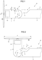
- FIG 1 shows schematically an embodiment of a nacelle device 1, which can be rotated about a rotation axis D from a propulsion position A (as in Figure 1 shown) can be pivoted into a buoyancy position B (see Figure 2 ).
- a drive device 12 with a propeller is arranged on the nacelle device 1.
- the pivoting of the nacelle device 1 - and thus also of the drive device 12 - is also reversible, so that the nacelle device 1 can be pivoted from the lift position B into the propulsion position A.
- This embodiment is therefore particularly suitable for a vertical take-off and landing aircraft 10.
- the nacelle device 1 is pivotably arranged on a pylon device 2, which in turn is arranged on a wing 11 of the vertical take-off and landing aircraft 10, which is not fully shown here.
- the axis of rotation D is located inside the pylon device 2, so that the nacelle device 1 can rotate with its rear or lower part within the pylon device 2.
- an air guiding device 5 is arranged, with which cooling air L 1 , L 2 can be guided in an efficient and above all adaptive manner from the environment of the vertical take-off and landing aircraft 10, e.g. to an electric motor 13 of the drive unit 12.
- the nacelle device 1 has an air distribution means 8 in the rear area (seen in the propulsion position) around the axis of rotation D, which is attached to the Wall of the nacelle device 1.
- the air distribution means 8 can thus be pivoted with the nacelle device 1 about the axis of rotation D. This is e.g. Figure 2 recognizable because it is rotated 90° clockwise.
- the air distribution means 8 protrudes by a height H from the wall of the nacelle device 1 and is inclined in the direction of flight. This means that a second inlet opening 7 is at least partially oriented in the direction of flight.
- the air distribution means 8 can, for example, comprise a piece of pipe that is curved in the direction of flight. However, it can also be designed at least partially as a NACA inlet, via which the second air flow L 2 can reach the interior of the nacelle device 1 or the pylon device 2.
- the propeller of the drive device 12 is oriented upwards so that (during operation) a rotating surface F of the propeller lies partially above the pylon device 2.
- a first inlet opening 6 is arranged in the surface of the pylon device 2 in the region of the vertical projection of the rotating surface F.
- the air flow L 1 conveyed by the propeller thus also hits the first inlet opening 6 so that the air flow L 1 can be guided into the air guiding device 5 inside the pylon device 2.
- the air guiding device 5 here has a channel which connects to the air distribution means 8 in the lift position B and has now been pivoted in this direction. This allows the air to reach the interior of the nacelle device 5 and, for example, cool the electric motor 13 even in this flight phase.
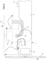
- the coordinate system below the propeller in the lift position B indicates the radial position of the propeller on the x-axis, and the total pressure in VTOL flight is shown on the y-axis. It is clear that a maximum of the total pressure lies in a certain radial area of the rotation surface F.
- the pressure conditions in the propulsion position A are also shown in the form of a coordinate system, with the axes tilted by 90°; the x-axis shows the total pressure of the air conveyed by the propeller, the y-axis shows the radial position of the propeller.
- the maximum of the total pressure is - analogous to the lift position - in the area between the hub of the propeller and the tip of the propeller. Since the second inlet opening 7 is close to the hub of the propeller, the height H (see Figure 1 ), with which the second inlet opening 7 protrudes from the housing of the nacelle device 1, must be designed accordingly so that a sufficiently large second air flow L 2 can flow in in this position.
- FIG. 4 to 6 is a second embodiment of a modification of the first embodiment according to the Figures 1 to 3
- the pivotable part of the nacelle device 1 is shorter, so that the inlet for the air flow L 2 is arranged directly above the electric motor 13.
- the air flows L 1 , L 2 in the Figures 4 to 6 not shown, since in the second embodiment they are analogous to the first embodiment.
Landscapes
- Engineering & Computer Science (AREA)
- Aviation & Aerospace Engineering (AREA)
- Chemical & Material Sciences (AREA)
- Combustion & Propulsion (AREA)
- Mechanical Engineering (AREA)
- Wind Motors (AREA)
Abstract
Description
- Die Erfindung betrifft eine Nacellevorrichtung mit den Merkmalen des Anspruchs 1 und ein Senkrecht-Start und -Landungsluftfahrzeug mit den Merkmalen des Anspruchs 10.
- Luftfahrzeuge, die senkrecht starten und landen können (im Englischen: VTOL: vertical take off and landing), sind grundsätzlich bekannt. Wird als Antriebsvorrichtung eines solchen Luftfahrzeuges ein elektrischer Antrieb verwendet, so wird dieses auch als eVTOL Luftfahrzeug bezeichnet. Gerade für den Einsatz von Luftfahrzeugen im städtischen Bereich (im Englischen: UAM: urban air mobility) sind solche Luftfahrzeuge von erheblichem Interesse.
- Dabei kommen grundsätzlich unterschiedliche Bauformen zum Einsatz, wie z.B. reine Drehflügler oder Bauformen mit schwenkbaren Tragflächen oder schwenkbaren Antrieben.
- Bei einer Ausführung mit verschwenkbaren Antrieben werden diese z.B. mittels einer schwenkbaren Nacellevorrichtung (auch als Gondeln bezeichnet) von einer Auftriebsposition in eine Vortriebsposition gebracht. Die Nacellevorrichtungen sind dabei über eine Pylonvorrichtung mit einer Tragfläche verbunden, wobei die Verschwenkung um eine Achse am Gehäuse der Pylonvorrichtung erfolgt.
- Es besteht die Aufgabe, verbesserte Nacellevorrichtungen zu schaffen, die insbesondere eine effiziente Verteilung von Kühlluft erlauben.
- Die Aufgabe wird durch eine Nacellevorrichtung mit den Merkmalen des Anspruchs 1 gelöst.
- Die Nacellevorrichtung für ein Senkrecht-Start- und -Landungsluftfahrzeug weist eine Antriebsvorrichtung auf, wobei die Nacellevorrichtung über eine Pylonvorrichtung mit einer Tragfläche des Senkrecht-Start- und - Landungsluftfahrzeugs verbunden ist. Die Nacellevorrichtung und damit auch die Antriebsvorrichtung, sind um eine Drehachse zwischen einer Vortriebsposition und einer Auftriebsposition relativ zur Pylonvorrichtung verschwenkbar.
- Die Nacellevorrichtung weist eine Luftleitvorrichtung auf, die mindestens zwei Einlassöffnungen aufweist. Die erste Einlassöffnung ist an der Pylonvorrichtung in dem Bereich angeordnet, in dem der von der Antriebsvorrichtung in der Auftriebsposition (primär vertikal nach unten) geförderte erste Luftstrom auf die Pylonvorrichtung auftrifft. Damit kann der nach unten ausgerichtete erste Luftstrom, der z. B. von einem Propeller der Antriebsvorrichtung gefördert wird, von der ersten Einlassöffnung aufgefangen werden.
- Die Nacellevorrichtung weist ferner eine zweite Einlassöffnung auf, die an der Nacellevorrichtung selbst und / oder der Pylonvorrichtung so angeordnet ist, dass ein zweiter Luftstrom in der Vortriebsposition durch die zweite Einlassöffnung einströmen kann, so dass auch dieser Luftstrom als Kühlluft nutzbar ist.
- Ferner weist die Luftleitvorrichtung ein Luftverteilungsmittel auf, mit dem die strömenden Luftmengen aus der ersten Einlassöffnung und der zweiten Einlassöffnung im Inneren der Nacellevorrichtung steuerbar sind. Damit kann mit einem Mittel, dem Luftverteilungsmittel, die Strömung der Kühlluft in den unterschiedlichen Betriebspositionen eingestellt werden, was Gewicht spart.
- Dabei kann das Luftverteilungsmittel in einer Ausführungsform drehbar an der Nacellevorrichtung angeordnet sein, so dass es in der Vortriebsposition den zweiten Luftstrom von der zweiten Einlassöffnung in die Luftleitvorrichtung führt und in der Auftriebsposition den ersten Luftstrom von der ersten Einlassöffnung in die Luftleitvorrichtung führt. Durch die Drehung der Nacellevorrichtung um die Drehachse wird jeweils das Luftverteilungsmittel mitgedreht, wobei es sich in den beiden Positionen jeweils an die Luftleitvorrichtung (z.B. Kanäle, Rohre etc.) anschließt, so dass die einströmenden Luftströme ins Innere geführt werden können. Somit sind außer der ohnehin beweglichen Nacellevorrichtung keine weiteren beweglichen Teile notwendig.
- Für eine effiziente Aufnahme der Luftströme kann das Luftverteilungsmittel in einer Ausführungsform in der Vortriebsposition so orientiert sein, dass die zweite Einlassöffnung mindestens teilweise in Flugrichtung orientiert ist. Damit kann die zweite Einlassöffnung Luft aufnehmen, die vom Propeller in Vortriebsrichtung gefördert wird. Die Einlassöffnung kann somit senkrecht oder auch geneigt zur Flugrichtung geneigt sein, solange der freie Querschnitt Luft aus der Flugrichtung aufnehmen kann.
- In einer weiteren Ausführungsform kann das Luftverteilungsmittel in der Auftriebsposition so orientiert sein, dass es an einen Zulaufkanal für den ersten Luftstrom von der ersten Einlassöffnung anschließbar ist. Damit werden zusätzliche Leitungen zur Luftverteilung in der Nacellevorrichtung eingespart, was zu einer Gewichtsreduktion führt.
- Dabei kann das Luftverteilungsmittel mindestens teilweise rohrförmig oder als NACA-Einlass ausgebildet sein, so dass in beiden Fällen eine effiziente Einströmung in die Luftleitvorrichtung der Nacellevorrichtung möglich ist.
- Wenn die Antriebsvorrichtung in einer Ausführungsvorrichtung einen Propeller aufweist, der im Betrieb eine Drehfläche aufweist, kann die erste Einlassöffnung in dem Bereich der senkrechten Projektion der Drehfläche auf die Oberseite der Pylonvorrichtung liegen. Damit ist sichergestellt, dass der gezielt nach unten geförderte Luftstrom auf die Pylonvorrichtung mit der ersten Einlassöffnung trifft.
- Insbesondere kann die erste Einlassöffnung vertikal unterhalb des Bereiches der Drehfläche angeordnet sein, in dem der Gesamtdruck der vom Propeller geförderten Luft maximal ist. Damit würde der geförderte Luftstrom effizient von der ersten Einlassöffnung eingefangen.
- Ferner kann die über die Antriebsvorrichtung und über die erste Einlassöffnung und / oder über die zweite Einlassöffnung eingeführten Luftströme Kühlluft zur Antriebsvorrichtung und / oder zu einem Elektromotor geführt werden.
- Für eine effiziente Förderung der Luft in der Vortriebsposition kann die zweite Einlassöffnung mindestens teilweise als NACA-Einlauf ausgebildet sein.
- Die Aufgabe wird auch durch ein Senkrecht- Start- und -Landungsluftfahrzeug mit den Merkmalen des Anspruchs 10 gelöst. Dabei kann die Antriebseinheit mit einer Verschwenkvorrichtung gekoppelt sein, die als Hebelgetriebe ausgebildet ist, insbesondere mit einem hydraulisch, elektrisch oder pneumatisch angetriebenen Hebelgetriebe.
- Im Zusammenhang mit den Figuren werden Ausführungsbeispiele erläutert. Dabei zeigt
-
Figur 1 eine schematische Darstellung einer ersten Ausführungsform einer Nacellevorrichtung in einer ersten Position (Vortriebsposition); -
Figur 2 eine schematische Darstellung der ersten Ausführungsform der Nacellevorrichtung gemäßFigur 1 in einer zweiten Position (Auftriebsposition); -
Figur 3 eine schematische Darstellung der ersten Ausführungsform gemäßFiguren 1 und 2 mit einer Darstellung der Strömungen in einer Luftleitvorrichtung; -
Figur 4 eine schematische Darstellung einer zweiten Ausführungsform einer Nacellevorrichtung in einer ersten Position (Vortriebsposition); -
Figur 5 eine schematische Darstellung der zweiten Ausführungsform der Nacellevorrichtung gemäßFigur 4 in einer zweiten Position (Auftriebsposition); -
Figur 6 eine schematische Darstellung der zweiten Ausführungsform gemäßFiguren 4 und 5 mit einer Darstellung der Strömungen in einer Luftleitvorrichtung; -
Figur 1 zeigt in schematischer Weise eine Ausführungsform einer Nacellevorrichtung 1, die um eine Drehachse D von einer Vortriebsposition A (wie inFigur 1 dargestellt) in eine Auftriebsposition B verschwenkbar ist (sieheFigur 2 ). An der Nacellevorrichtung 1 ist eine Antriebsvorrichtung 12 mit einem Propeller angeordnet. - Die Verschwenkung der Nacellevorrichtung 1 - und damit auch der Antriebsvorrichtung 12 - ist auch umkehrbar, so dass die Nacellevorrichtung 1 von der Auftriebsposition B in die Vortriebsposition A schwenkbar ist. Damit ist diese Ausführungsform besonders für ein Senkrecht-Start- und -Landungsluftfahrzeug 10 geeignet.
- In der hier dargestellten Ausführungsform ist die Nacellevorrichtung 1 verschwenkbar an einer Pylonvorrichtung 2 angeordnet, die wiederum an einer Tragfläche 11 des hier nicht vollständig dargestellten Senkrecht-Start- und - Landungsluftfahrzeugs 10 angeordnet ist.
- Die Drehachse D liegt bei der hier dargestellten Ausführungsform im Inneren der Pylonvorrichtung 2, so dass sich die Nacellevorrichtung 1 mit ihrem hinteren oder unteren Teil innerhalb der Pylonvorrichtung 2 drehen kann.
- Im Inneren der Nacellevorrichtung 1 und der Pylonvorrichtung 2 ist eine Luftleitvorrichtung 5 angeordnet, mit der Kühlluft L1, L2 in effizienter und vor allem adaptiver Weise von der Umgebung des Senkrecht-Start- und - Landungsluftfahrzeugs 10 z.B. zu einem Elektromotor 13 der Antriebseinheit 12 geführt werden kann.
- Die unterschiedlichen Arten der Luftführung in den unterschiedlichen Positionen A, B sind im Folgenden dargestellt.
- Dabei weist die Nacellevorrichtung 1 im hinteren Bereich (gesehen in der Vortriebsposition) um die Drehachse D ein Luftverteilungsmittel 8 auf, das an der Wandung der Nacellevorrichtung 1 angeordnet ist. Das Luftverteilungsmittel 8 ist somit mit der Nacellevorrichtung 1 um die Drehachse D schwenkbar. Dies ist z.B. an der
Figur 2 erkennbar, da es dort um 90° im Uhrzeigersinn verschwenkt liegt. - In der Vortriebsposition gemäß
Figur 1 ragt das Luftverteilungsmittel 8 um eine Höhe H aus der Wandung der Nacellevorrichtung 1 hinaus und ist in Flugrichtung geneigt. Dies bedeutet, dass eine zweite Einlassöffnung 7 mindestens teilweise in Flugrichtung orientiert ist. - Damit kann ein zweiter Luftstrom L2 von der Umgebung des Senkrecht-Start- und -Landungsluftfahrzeugs 10 über die zweite Einlassöffnung 7 in die Luftleitvorrichtung 5 im Inneren der Nacellevorrichtung 1 geführt werden.
- Das Luftverteilungsmittel 8 kann dabei z.B. ein Stück Rohr aufweisen, dass in Richtung der Flugrichtung gekrümmt ist. Es kann aber auch mindestens teilweise als NACA-Einlass ausgebildet sein, über die der zweite Luftstrom L2 in das Innere der Nacellevorrichtung 1 oder der Pylonvorrichtung 2 gelangen kann.
- In der Auftriebsposition B (siehe
Figur 2 ) ist der Propeller der Antriebsvorrichtung 12 nach oben ausgerichtet, so dass (im Betrieb) eine Drehfläche F des Propellers teilweise oberhalb der Pylonvorrichtung 2 liegt. In der Oberfläche der Pylonvorrichtung 2 ist eine erste Einlassöffnung 6 in dem Bereich der senkrechten Projektion der Drehfläche F angeordnet. Damit trifft der von dem Propeller geförderte Luftstrom L1 auch auf die erste Einlassöffnung 6, so dass der Luftstrom L1 in die Luftleitvorrichtung 5 im Inneren der Pylonvorrichtung 2 geführt werden kann. - Die Luftleitvorrichtung 5 weist hier einen Kanal auf, der in der Auftriebsposition B an das Luftverteilungsmittel 8 anschließt und jetzt in diese Richtung geschwenkt wurde. Damit kann die Luft in das Innere der Nacellevorrichtung 5 gelangen und z.B. den Elektromotor 13 auch in dieser Flugphase kühlen.
- Durch die Verwendung einer Nacellevorrichtung 1 mit einem mit-verschwenkbaren Luftverteilungsmittel 8 wird Gewicht eingespart, wobei gleichzeitig insbesondere die hohen Kühlanforderungen für den Fall des Auftriebs erfüllt werden können. Die vom Propeller nach unten geförderte Luft kann effizient als Kühlluft genutzt werden, was wichtig ist, da in dieser Position kaum Fahrtwind als Kühlluft zur Verfügung steht.
- Dabei liegen bestimmte Druckverhältnisse vor, die in schematischer Weise in der
Figur 3 dargestellt sind, wobei die beiden Positionen A, B der Nacellevorrichtung 1 hier überlagert dargestellt sind. - Das Koordinatensystem unterhalb des Propellers in der Auftriebsposition B gibt auf der x-Achse die radiale Position des Propellers an, auf der y-Achse ist der Gesamtdruck im VTOL Flug dargestellt. Es ist ersichtlich, dass ein Maximum des Gesamtdrucks in einem gewissen radialen Bereich der Drehfläche F liegt.
- In der
Figur 3 sind auch die Druckverhältnisse in der Vortriebsposition A in Form eines Koordinatensystems dargestellt, wobei die Achsen hier um 90° gekippt dargestellt sind; die x-Achse zeigt den Gesamtdruck der vom Propeller geförderten Luft an, die y-Achse gibt die radiale Position des Propellers an. Das Maximum des Gesamtdrucks liegt - analog zur Auftriebsposition - im Bereich zwischen der Nabe des Propellers und der Spitze des Propellers. Da die zweite Einlassöffnung 7 hier nahe an der Nabe des Propellers liegt, muss die Höhe H (sieheFigur 1 ), mit der die zweite Einlassöffnung 7 aus dem Gehäuse der Nacellevorrichtung 1 herausragt, entsprechend ausgebildet sein, damit ein ausreichend großer zweiter Luftstrom L2 in dieser Position einströmen kann. - In den
Figuren 4 bis 6 ist als zweite Ausführungsform eine Abwandlung der ersten Ausführungsform gemäß denFiguren 1 bis 3 dargestellt. In der zweiten Ausführungsform ist verschwenkbare Teil der Nacellevorrichtung 1 kürzer ausgebildet, so dass der Einlauf für den Luftstrom L2 direkt über dem Elektromotor 13 angeordnet ist. Aus Gründen der Übersichtlichkeit sind die Luftströme L1, L2 in denFiguren 4 bis 6 nicht darstellt, da sie in der zweiten Ausführungsform analog zur ersten Ausführungsform verlaufen. -
- 1
- Nacellevorrichtung
- 2
- Pylonvorrichtung
- 5
- Luftleitvorrichtung
- 6
- erste Einlassöffnung
- 7
- zweite Einlassöffnung
- 8
- Luftverteilungsmittel
- 10
- Senkrecht-Start- und -Landungsluftfahrzeug
- 11
- Tragfläche
- 12
- Antriebsvorrichtung, Rotor
- 13
- Elektromotor
- A
- Vortriebsposition der Antriebsvorrichtung
- B
- Auftriebsposition der Antriebsvorrichtung
- D
- Drehachse der verschwenkbaren Nacellevorrichtung
- F
- Drehfläche des Propellers
- L1
- erster geförderter Luftstrom
- L2
- zweiter geförderter Luftstrom
- R
- Flugrichtung
Claims (11)
- Nacellevorrichtung (1) für ein Senkrecht-Start- und -Landungsluftfahrzeug (10), wobei die Nacellevorrichtung (1) mit einer Antriebsvorrichtung (12) über eine Pylonvorrichtung (2) mit einer Tragfläche (11) des Senkrecht-Start- und - Landungsluftfahrzeugs (10) verbunden ist und um eine Drehachse (D) zwischen einer Vortriebsposition (A) und einer Auftriebsposition (B) relativ zur Pylonvorrichtung (2) verschwenkbar ist,
gekennzeichnet durcheine Luftleitvorrichtung (5)mit einer ersten Einlassöffnung (6) an der Pylonvorrichtung (2), die in dem Bereich angeordnet ist, in dem der von der Antriebsvorrichtung (12) in der Auftriebsposition (B) geförderte erste Luftstrom (L1) auf die Pylonvorrichtung (2) auftrifft undmit einer zweite Einlassöffnung (7), die an der Nacellevorrichtung (1) und / oder der Pylonvorrichtung (2) so angeordnet ist, dass ein zweiter Luftstrom (L2) in der Vortriebsposition durch die zweite Einlassöffnung (7) einströmen kann, wobeidie Luftleitvorrichtung (5) ein Luftverteilungsmittel (8) aufweist, mit dem die strömenden Luftmengen (L1, L2) aus der ersten Einlassöffnung (6) und der zweiten Einlassöffnung (7) im Inneren der Nacellevorrichtung (1) steuerbar sind. - Nacellevorrichtung (1) nach Anspruch 1, dadurch gekennzeichnet, dass das Luftverteilungsmittel (8) drehbar an der Nacellevorrichtung (1) angeordnet ist, so dass es in der Vortriebsposition (A) den zweiten Luftstrom (L2) von der zweiten Einlassöffnung (7) in die Luftleitvorrichtung (5) führt und in der Auftriebsposition (B) den ersten Luftstrom (L1) von der ersten Einlassöffnung (6) in die Luftleitvorrichtung (5) führt.
- Nacellevorrichtung (1) nach Anspruch 1 oder 2, dadurch gekennzeichnet, dass das Luftverteilungsmittel (8) in der Vortriebsposition (A) so orientiert ist, dass die zweite Einlassöffnung (7) mindestens teilweise in Flugrichtung (R) orientiert ist.
- Nacellevorrichtung (1) nach mindestens einem der vorhergehenden Ansprüche, dadurch gekennzeichnet, dass das Luftverteilungsmittel (8) in der Auftriebsposition (B) so orientiert ist, dass es an einen Zulaufkanal für den ersten Luftstrom (L1) von der ersten Einlassöffnung (6) anschließbar ist.
- Nacellevorrichtung (1) nach mindestens einem der vorhergehenden Ansprüche, dadurch gekennzeichnet, dass das Luftverteilungsmittel (8) mindestens teilweise rohrförmig oder als NACA-Einlass ausgebildet ist.
- Nacellevorrichtung nach mindestens einem der vorhergehenden Ansprüche, dadurch gekennzeichnet, dass die Antriebsvorrichtung (12) einen Propeller aufweist und der im Betrieb eine Drehfläche (F) aufweist, wobei die erste Einlassöffnung (6) in dem Bereich der senkrechten Projektion der Drehfläche (F) auf die Oberseite der Pylonvorrichtung (2) liegt.
- Nacellevorrichtung nach Anspruch 6, dadurch gekennzeichnet, dass die erste Einlassöffnung (6) vertikal unterhalb des Bereiches der Drehfläche (F) angeordnet ist, in dem der Gesamtdruck der vom Propeller geförderten Luft maximal ist.
- Nacellevorrichtung dadurch gekennzeichnet, dass die von der Antriebsvorrichtung (12) über die erste Einlassöffnung (6) und / oder die zweite Einlassöffnung (7) eingeführten Luftströme (L1, L2) als Kühlluft zur Antriebsvorrichtung (12) und / oder einem Elektromotor (1) führbar sind.
- Nacellevorrichtung nach mindestens einem der vorhergehenden Ansprüche, dadurch gekennzeichnet, dass die zweite Einlassöffnung (7) mindestens teilweise als NACA-Einlauf ausgebildet ist.
- Senkrecht- Start- und -Landungsluftfahrzeug (10) mit mindestens einer Pylonvorrichtung (2) an einem Flügel (11), wobei die mindestens eine Pylonvorrichtung (2) eine Luftleitvorrichtung (5) nach mindestens einem der Ansprüche 1 bis 9 aufweist.
- Senkrecht- Start- und -Landungsluftfahrzeug (10) nach Anspruch 10, dadurch gekennzeichnet, dass die Antriebseinheit (12) mit einer Verschwenkvorrichtung gekoppelt ist, die als Hebelgetriebe ausgebildet ist, insbesondere mit einem hydraulisch, elektrisch oder pneumatisch angetriebenen Hebelgetriebe.
Applications Claiming Priority (1)
| Application Number | Priority Date | Filing Date | Title |
|---|---|---|---|
| DE102022131771.4A DE102022131771A1 (de) | 2022-11-30 | 2022-11-30 | Nacellevorrichtung mit Luftleitvorrichtung und Senkrecht-Start und -Landungsluftfahrzeug |
Publications (1)
| Publication Number | Publication Date |
|---|---|
| EP4378830A1 true EP4378830A1 (de) | 2024-06-05 |
Family
ID=90231699
Family Applications (1)
| Application Number | Title | Priority Date | Filing Date |
|---|---|---|---|
| EP23212352.1A Withdrawn EP4378830A1 (de) | 2022-11-30 | 2023-11-27 | Nacellevorrichtung mit luftleitvorrichtung und senkrecht-start und -landungsluftfahrzeug |
Country Status (3)
| Country | Link |
|---|---|
| US (1) | US20240174369A1 (de) |
| EP (1) | EP4378830A1 (de) |
| DE (1) | DE102022131771A1 (de) |
Families Citing this family (2)
| Publication number | Priority date | Publication date | Assignee | Title |
|---|---|---|---|---|
| DE102022131799A1 (de) * | 2022-11-30 | 2024-06-06 | Rolls-Royce Deutschland Ltd & Co Kg | Luftleitvorrichtung eines Senkrecht-Start- und -Landungsluftfahrzeugs und ein Senkrecht-Start- und -Landungsluftfahrzeug |
| CN121404527B (zh) * | 2025-12-30 | 2026-04-10 | 四川沃飞长空科技发展有限公司 | 电推进散热系统、动力装置及飞行器 |
Citations (2)
| Publication number | Priority date | Publication date | Assignee | Title |
|---|---|---|---|---|
| WO2021222528A1 (en) * | 2020-05-01 | 2021-11-04 | Overair, Inc. | Adaptive cooling system for an aircraft |
| US20220194618A1 (en) * | 2020-12-22 | 2022-06-23 | Hyundai Motor Company | Air mobility vehicle |
Family Cites Families (7)
| Publication number | Priority date | Publication date | Assignee | Title |
|---|---|---|---|---|
| FR2791634B1 (fr) * | 1999-03-30 | 2001-06-15 | Eurocopter France | Perfectionnements aux aeronefs convertibles a rotors basculants |
| US7472863B2 (en) * | 2004-07-09 | 2009-01-06 | Steve Pak | Sky hopper |
| US9126678B2 (en) * | 2013-03-13 | 2015-09-08 | Bell Helicopter Textron Inc. | Spindle mounted tiltrotor pylon with fixed engine arrangement |
| DE102016125656B4 (de) * | 2016-12-23 | 2021-02-18 | Airbus Defence and Space GmbH | Luftfahrzeug mit einem Kühlsystem und Kühlverfahren |
| DE102018116170A1 (de) * | 2018-07-04 | 2020-01-09 | Dr. Ing. H.C. F. Porsche Aktiengesellschaft | Luftfahrzeug |
| CN213974458U (zh) * | 2020-08-07 | 2021-08-17 | 上海峰飞航空科技有限公司 | 垂直起降空中无人机以及用于空中无人机的冷却系统 |
| KR102552953B1 (ko) * | 2021-11-22 | 2023-07-06 | 한국항공우주연구원 | 전기추진항공기 |
-
2022
- 2022-11-30 DE DE102022131771.4A patent/DE102022131771A1/de active Pending
-
2023
- 2023-11-20 US US18/514,928 patent/US20240174369A1/en not_active Abandoned
- 2023-11-27 EP EP23212352.1A patent/EP4378830A1/de not_active Withdrawn
Patent Citations (2)
| Publication number | Priority date | Publication date | Assignee | Title |
|---|---|---|---|---|
| WO2021222528A1 (en) * | 2020-05-01 | 2021-11-04 | Overair, Inc. | Adaptive cooling system for an aircraft |
| US20220194618A1 (en) * | 2020-12-22 | 2022-06-23 | Hyundai Motor Company | Air mobility vehicle |
Also Published As
| Publication number | Publication date |
|---|---|
| DE102022131771A1 (de) | 2024-06-06 |
| US20240174369A1 (en) | 2024-05-30 |
Similar Documents
| Publication | Publication Date | Title |
|---|---|---|
| EP2178748B1 (de) | Hochauftriebssystem für ein flugzeug | |
| EP1327758B1 (de) | Lufteinlauf-Vorrichtung für ein Hilfstriebwerk in einem Flugzeug | |
| DE2846217C2 (de) | Flugkörper | |
| EP2018288B1 (de) | Vorrichtung zum führen der bewegung eines windabweisers | |
| DE102022131771A1 (de) | Nacellevorrichtung mit Luftleitvorrichtung und Senkrecht-Start und -Landungsluftfahrzeug | |
| EP2280867B1 (de) | Lateral-kopplungsvorrichtung zum halten und führen zumindest eines aerodynamischen körpers gegenüber dem hauptflügel eines flugzeugs, tragflügel und flugzeug mit einer solchen lateral-kopplungsvorrichtung | |
| CH665185A5 (de) | Drehfluegelflugkoerper. | |
| DE102021124376A1 (de) | Flugzeug zum vertikalen starten und landen sowie flügelvorrichtung | |
| DE102019118023B3 (de) | Luftfahrzeug | |
| EP0970330B1 (de) | Stufenventil, insbesondere kabinenabluftventil in einem fluggerät, und verfahren zur regulierung des kabinendrucks | |
| DE102021210495B4 (de) | Faltpropeller für luftmobilität | |
| CH637031A5 (en) | Aeration arrangement at a device immersed in a liquid | |
| DE102008032789A1 (de) | Flugzeug mit zumindest zwei in Spannweitenrichtung der Flügel voneinander beabstandeten Antriebsmotoren | |
| DE3309677C2 (de) | Steuerungsvorrichtung zur Einstellwinkelverstellung von Rotorblättern an schuberzeugenden Rotoren | |
| DE102019123725B4 (de) | Auftriebs- und Flugsteuerungseinheit für ein Fluggerät und Fluggerät | |
| DE102021110538B4 (de) | Luftfahrzeugpropeller und Luftfahrzeug | |
| DE102023204091B3 (de) | Verschlusssystem | |
| DE102023133781B3 (de) | Mantelpropeller für ein Luftfahrzeug und Luftfahrzeug | |
| WO2022012827A1 (de) | Tragflügel-verschlusssystem für vertikalantriebe in evtol-fahrzeugen | |
| DE102022131791A1 (de) | Nacellevorrichtung und Senkrecht-Start und -Landungsluftfahrzeug | |
| DE102020128799A1 (de) | Antriebseinheit für einen Drehflügler und Drehflügler | |
| DE3626979C2 (de) | ||
| DE102013016445A1 (de) | Luftausströmeinrichtung für einen Kraftwagen, insbesondere einen Personenkraftwagen | |
| DE102021204732B4 (de) | Einfahrbare propellereinrichtung eines luftmobilitätsfahrzeugs | |
| DE102020200746B4 (de) | Multicopter und Verfahren zum Betreiben eines Multicopters |
Legal Events
| Date | Code | Title | Description |
|---|---|---|---|
| PUAI | Public reference made under article 153(3) epc to a published international application that has entered the european phase |
Free format text: ORIGINAL CODE: 0009012 |
|
| STAA | Information on the status of an ep patent application or granted ep patent |
Free format text: STATUS: THE APPLICATION HAS BEEN PUBLISHED |
|
| AK | Designated contracting states |
Kind code of ref document: A1 Designated state(s): AL AT BE BG CH CY CZ DE DK EE ES FI FR GB GR HR HU IE IS IT LI LT LU LV MC ME MK MT NL NO PL PT RO RS SE SI SK SM TR |
|
| STAA | Information on the status of an ep patent application or granted ep patent |
Free format text: STATUS: REQUEST FOR EXAMINATION WAS MADE |
|
| 17P | Request for examination filed |
Effective date: 20240702 |
|
| RBV | Designated contracting states (corrected) |
Designated state(s): AL AT BE BG CH CY CZ DE DK EE ES FI FR GB GR HR HU IE IS IT LI LT LU LV MC ME MK MT NL NO PL PT RO RS SE SI SK SM TR |
|
| STAA | Information on the status of an ep patent application or granted ep patent |
Free format text: STATUS: THE APPLICATION HAS BEEN WITHDRAWN |
|
| 18W | Application withdrawn |
Effective date: 20250121 |