EP4378675A1 - Mold for producing annular rubber component - Google Patents
Mold for producing annular rubber component Download PDFInfo
- Publication number
- EP4378675A1 EP4378675A1 EP23212117.8A EP23212117A EP4378675A1 EP 4378675 A1 EP4378675 A1 EP 4378675A1 EP 23212117 A EP23212117 A EP 23212117A EP 4378675 A1 EP4378675 A1 EP 4378675A1
- Authority
- EP
- European Patent Office
- Prior art keywords
- inner mold
- mold segments
- segments
- actuator
- radially
- Prior art date
- Legal status (The legal status is an assumption and is not a legal conclusion. Google has not performed a legal analysis and makes no representation as to the accuracy of the status listed.)
- Granted
Links
Images


Classifications
-
- B—PERFORMING OPERATIONS; TRANSPORTING
- B29—WORKING OF PLASTICS; WORKING OF SUBSTANCES IN A PLASTIC STATE IN GENERAL
- B29D—PRODUCING PARTICULAR ARTICLES FROM PLASTICS OR FROM SUBSTANCES IN A PLASTIC STATE
- B29D30/00—Producing pneumatic or solid tyres or parts thereof
- B29D30/06—Pneumatic tyres or parts thereof (e.g. produced by casting, moulding, compression moulding, injection moulding, centrifugal casting)
- B29D30/0601—Vulcanising tyres; Vulcanising presses for tyres
- B29D30/0605—Vulcanising presses characterised by moulds integral with the presses having radially movable sectors
-
- B—PERFORMING OPERATIONS; TRANSPORTING
- B29—WORKING OF PLASTICS; WORKING OF SUBSTANCES IN A PLASTIC STATE IN GENERAL
- B29D—PRODUCING PARTICULAR ARTICLES FROM PLASTICS OR FROM SUBSTANCES IN A PLASTIC STATE
- B29D30/00—Producing pneumatic or solid tyres or parts thereof
- B29D30/06—Pneumatic tyres or parts thereof (e.g. produced by casting, moulding, compression moulding, injection moulding, centrifugal casting)
- B29D30/0601—Vulcanising tyres; Vulcanising presses for tyres
- B29D30/0606—Vulcanising moulds not integral with vulcanising presses
- B29D30/0629—Vulcanising moulds not integral with vulcanising presses with radially movable sectors
-
- B—PERFORMING OPERATIONS; TRANSPORTING
- B29—WORKING OF PLASTICS; WORKING OF SUBSTANCES IN A PLASTIC STATE IN GENERAL
- B29D—PRODUCING PARTICULAR ARTICLES FROM PLASTICS OR FROM SUBSTANCES IN A PLASTIC STATE
- B29D30/00—Producing pneumatic or solid tyres or parts thereof
- B29D30/06—Pneumatic tyres or parts thereof (e.g. produced by casting, moulding, compression moulding, injection moulding, centrifugal casting)
- B29D30/0601—Vulcanising tyres; Vulcanising presses for tyres
- B29D30/0661—Rigid cores therefor, e.g. annular or substantially toroidal cores
-
- B—PERFORMING OPERATIONS; TRANSPORTING
- B29—WORKING OF PLASTICS; WORKING OF SUBSTANCES IN A PLASTIC STATE IN GENERAL
- B29D—PRODUCING PARTICULAR ARTICLES FROM PLASTICS OR FROM SUBSTANCES IN A PLASTIC STATE
- B29D30/00—Producing pneumatic or solid tyres or parts thereof
- B29D30/06—Pneumatic tyres or parts thereof (e.g. produced by casting, moulding, compression moulding, injection moulding, centrifugal casting)
- B29D30/0681—Parts of pneumatic tyres; accessories, auxiliary operations
-
- B—PERFORMING OPERATIONS; TRANSPORTING
- B29—WORKING OF PLASTICS; WORKING OF SUBSTANCES IN A PLASTIC STATE IN GENERAL
- B29D—PRODUCING PARTICULAR ARTICLES FROM PLASTICS OR FROM SUBSTANCES IN A PLASTIC STATE
- B29D30/00—Producing pneumatic or solid tyres or parts thereof
- B29D30/06—Pneumatic tyres or parts thereof (e.g. produced by casting, moulding, compression moulding, injection moulding, centrifugal casting)
- B29D30/0601—Vulcanising tyres; Vulcanising presses for tyres
- B29D30/0606—Vulcanising moulds not integral with vulcanising presses
- B29D30/0629—Vulcanising moulds not integral with vulcanising presses with radially movable sectors
- B29D2030/0631—Means for forcing adjacent mould sectors away one from another, e.g. using springs or the like, to create repulsive forces
Definitions
- the present invention generally relates to a mold mechanism for curing/producing an annular rubber structure, in particular to a mold a tire or a tire part, and to a method and apparatus or mold container associated therewith, and more particularly, to a mold for the production of a non-pneumatic tire (NPT).
- NPT non-pneumatic tire
- segmented tire mold is the segmented tire mold, as opposed to a two-piece tire mold. Examples of segmented tire molds are described in US 3,779,677 and US 3,867,504 .
- US 3,779,677 discloses a tire mold in which tread mold segments are moved radially by a coned ring between sidewall plates which bear against the moving segments.
- Link means connecting each segment to the upper plate enable the segments to be retracted into the ring by moving the upper plate.
- the link means provides sufficient relative separation between the upper plate and the segments to prevent friction, wear, and binding therebetween during such retraction.
- the tire mold includes a pair of sidewall mold plates, each of which carries a tire sidewall molding surface.
- a plurality of tread mold segments collectively cooperate with the sidewall molding surfaces to form a closed tire molding cavity.
- the tread mold segments are mounted respectively on a plurality of carrier segments which are movable inwardly and outwardly with respect to the tire mold axis and particularly radially thereof.
- Each of the carrier segments is provided with an inclined surface, as well as guiding surfaces (e.g., a T-slot).
- the respective inclined surfaces cooperate with conjugately inclined surfaces carried by the closing ring and define collectively cones convergent on the mold axis outwardly, i.e., upwardly, of the upper platen. Radial movement of the respective segments inwardly, toward the axis, is effected by axial movement of the ring toward the lower sidewall plate. As the upper platen and ring move downwardly, engagement of the bottom surface of the segment with the flange surface of the lower sidewall plate prevents further axial movement of the segment, thereby converting the relative motion between the ring and the segment to radially inward movement of the segment.
- the pneumatic tire has been the solution of choice for vehicular mobility for over a century and is still dominant on the tire market today.
- Pneumatic tires are efficient at carrying loads because all of their structure is involved in carrying the load.
- Pneumatic tires are also desirable because they have low contact pressure, resulting in lower wear on roads due to the distribution of the load of the vehicle.
- Pneumatic tires also have low stiffness, which ensures a comfortable ride in a vehicle.
- the primary drawback to a pneumatic tire is that it requires compressed fluid (e.g., air or an inert gas). A conventional pneumatic tire is rendered useless after a complete loss of inflation pressure.
- a tire designed to operate without inflation pressure may eliminate many of the problems and compromises associated with a pneumatic tire. Neither pressure maintenance nor pressure monitoring is required. Structurally supported tires such as solid tires or other elastomeric structures to date have not provided the levels of performance required from a conventional pneumatic tire. A structurally supported tire solution that delivers pneumatic tire-like performance would be a desirous improvement.
- Non pneumatic tires are typically defined by their load carrying efficiency.
- So-called “bottom loaders” are essentially rigid structures that carry a majority of the load in the portion of the structure below the hub.
- Top loaders are designed so that all of the structure is involved in carrying the load. Top loaders thus have a higher load carrying efficiency than bottom loaders, allowing a design that has less mass.
- a shear band may be provided to transfer the load from contact with the ground through tension in the connecting structure (including, e.g., spokes or a connecting web) to the hub, creating a top loading structure.
- the connecting structure including, e.g., spokes or a connecting web
- its preferred form of deformation is shear over bending.
- the shear mode of deformation may occur because of inextensible membranes located on the radially inner and the radially outer portions of the shear band.
- Non-pneumatic tires may have a shear band made from a shear layer sandwiched between at least two layers of inextensible belts or membranes.
- the injection molding die comprises an upper die, a lower die, an inner die, and a taper die.
- the upper die comprises an upper die body and an upper tire side plate
- the lower die comprises a lower die body and a lower tire side plate.
- First inner modules and second inner modules of the inner die are alternately distributed around the taper die in sequence, and are driven by a first guide block and a second guide block which are arranged on the taper die to be connected and guided.
- the first inner modules are provided with symmetrical inclined planes which face the opening direction of the inner die, and the second inner modules are provided with symmetric inclined planes which face the retracting direction of the inner die.
- the first and second inner modules are actuated by means of a conical center mechanism, which pushes the first and second inner modules radially outward when it is moved in the direction of the taper and pulls the first and second inner modules inward when it is moved in the direction opposite to the taper.
- the invention relates to an inner mold mechanism in accordance with claim 1 or 9, respectively, and to a tire mold in accordance with claim 12.
- an inner mold mechanism for molding an annular structure comprises first inner mold segments and second inner mold segments, the first and second inner mold segments alternating with each other about a mold axis; a first axially movable actuator, the first actuator being mechanically connected to the first inner mold segments so as to move the first inner mold segments radially when the first actuator is moved axially; a second axially movable actuator, the second actuator being mechanically connected to the second inner mold segments so as to move the second inner mold segments radially when the first actuator is moved axially.
- each one of the first inner mold segments may comprise a radially inner stem and a radially outer front body with an arced front surface.
- the front body may have flanges protruding in azimuthal direction beyond the stem so as to define recesses between the stem and the flanges.
- each one of the second inner mold segments may comprise a radially inner stem and a radially outer front body with an arced front surface.
- the front body of each second inner mold second may have flanges protruding in azimuthal direction beyond the stem so as to define recesses between the stem and the flanges.
- the flanges of the first inner mold segments and the flanges of the second inner mold segments may be shaped complementarily along the flange edges.
- Each one of the first and each of the second inner mold segments may be mechanically constrained to travel in axial direction.
- the first actuator may be connected to the first inner mold segments by respective first prismatic joints and the second actuator may be connected to the second inner mold segments by respective second prismatic joints.
- the first and second prismatic joints may comprise a guide rail and a T-shaped slider sliding in the guide rail.
- the first inner mold segments may be configured movable between two extremal positions, a first retracted position and a first deployed position.
- the second inner mold segments may be configured movable between two extremal positions, a second retracted position and a second deployed position.
- the first and second inner mold segments may form together a substantially continuous inner mold surface.
- the first inner mold segments may have sides with recesses therein.
- the second inner mold segments may be further retracted than the first inner mold segments and the second inner mold segments may be lodged at least partially in the recesses in the sides of the first inner mold segments.
- the inner mold mechanism may comprise an equal number of first and second inner mold segments.
- the inner mold mechanism could comprise, e.g., from two to eight, preferably from three to five, first inner mold segments and the same number of second inner mold segments.
- a further inner mold mechanism for molding an annular tire structure comprising first inner mold segments and second inner mold segments arranged around a mold axis, the first and second inner mold segments alternating with each other in azimuthal direction about the mold axis, each of the first and each of the second inner mold segments being constrained to one linear degree of freedom in radial direction with respect to the mold axis; at least one axially movable actuator, the first actuator being mechanically connected to the first inner mold segments, the second inner mold segments or both the first and the second inner mold segments so as to move the first inner mold segments, the second inner mold segments or both the first and the second inner mold segments radially when the first actuator is moved axially; wherein each one of the first inner mold segments comprises a radially inner stem and a radially outer front body with an arced front surface, wherein the front body has flanges protruding in azimuthal direction beyond the stem so as to define recesses between the stem and the f
- each one of the second inner mold segments may comprise a radially inner stem, and the front body of each second inner mold segment may have flanges protruding in azimuthal direction beyond the stem so as to define recesses between the stem and the flanges.
- the flanges of the first inner mold segments and the flanges of the second inner mold segments may be shaped complementarily along their flange edges.
- the inner mold mechanism may comprise an equal number of first and second inner mold segments.
- the inner mold mechanism could comprise, e.g., from two to eight, preferably from three to five, first inner mold segments and the same number of second inner mold segments.
- the at least one axially movable actuator comprises a first actuator and a second actuator, the first actuator being mechanically connected to the first inner mold segments so as to move the first inner mold segments radially when the first actuator is moved axially, and the second actuator being connected to the second inner mold segments so as to move the second inner mold segments radially when the second actuator is moved axially.
- the first actuator may be connected to the first inner mold segments by respective first prismatic joints and the second actuator may be connected to the second inner mold segments by respective second prismatic joints.
- the first and second prismatic joints may comprise a guide rail and a T-shaped slider sliding in the guide rail.
- the invention in a third preferred aspect, relates to a mold for curing an annular tire structure, comprising: an outer mold structure and an inner mold structure, the outer and inner mold structures defining there between an openable and closable mold cavity for accommodating therein an annular tire structure to be cured; wherein the inner mold structure comprises: first inner mold segments and second inner mold segments arranged around a mold axis, the first and second inner mold segments alternating with each other in azimuthal direction about the mold axis, each of the first and each of the second inner mold segments being constrained to one linear degree of freedom in radial direction with respect to the mold axis; at least one axially movable actuator, the first actuator being mechanically connected to the first inner mold segments, the second inner mold segments or both the first and the second inner mold segments so as to move the first inner mold segments, the second inner mold segments or both the first and the second inner mold segments radially when the first actuator is moved axially; wherein each one of the first inner mold segments comprises a radially inner stem and
- Each one of the second inner mold segments may comprise a radially inner stem.
- the front body of each second inner mold segment may have flanges protruding in azimuthal direction beyond the stem so as to define recesses between the stem and the flanges.
- the flanges of the first inner mold segments and the flanges of the second inner mold segments may be shaped complementarily along their flange edges.
- the at least one axially movable actuator may comprise a first actuator and a second actuator, the first actuator being mechanically connected to the first inner mold segments so as to move the first inner mold segments radially when the first actuator is moved axially, and the second actuator being connected to the second inner mold segments so as to move the second inner mold segments radially when the second actuator is moved axially.
- the first actuator may be connected to the first inner mold segments by respective first prismatic joints and the second actuator may be connected to the second inner mold segments by respective second prismatic joints.
- the first and second prismatic joints may comprise a guide rail and a T-shaped slider sliding in the guide rail.
- rubber is intended to include both natural rubber compositions and synthetic rubber compositions.
- rubber may designate a cured rubber (typically obtained from unsaturated rubber by sulfur or non-sulfur vulcanization), green rubber or partially cured rubber, i.e., rubber wherein the molecular chains contain residual cure sites (e.g., allylic positions) available for crosslinking with other molecular chains.
- Rubber compositions may include e.g., reinforcing fillers, such as carbon black, precipitated amorphous silica, or the like.
- rubbers include neoprene (polychloroprene), polybutadiene (e.g., cis-1,4-polybutadiene), polyisoprene (e.g., cis-1,4-polyisoprene), butyl rubber, halobutyl rubber (such as, e.g., chlorobutyl rubber or bromobutyl rubber), styrene/isoprene/butadiene rubber, copolymers of 1,3-butadiene or isoprene with monomers such as, e.g., styrene, acrylonitrile, and methyl methacrylate.
- Other types of rubber include carboxylated rubber, silicon-coupled rubber, or tin-coupled star-branched polymers.
- axial and axially are used herein to refer to lines or directions that are parallel to the axis of rotation of the tire and thus also parallel to the central axis of the tire mold.
- radial and radially are used to mean the direction of a line intersecting the tire's axis or the mold's axis of rotation at right angle.
- azimuthal or “circumferential” refers to a direction that is perpendicular to both the radial and axial directions in the location under consideration. Instead of “azimuthal,” the word “angular” or “circumferential” may be used.
- Figs. 1 to 4 illustrate an inner mold mechanism 10 for molding an annular structure in accordance with an embodiment of the invention as well as a mold 20 featuring such an inner mold mechanism 10.
- the inner mold mechanism 10 comprises first inner mold segments 12A and second inner mold segments 12B arranged circumferentially about the mold axis.
- the first and second inner mold segments 12A, 12B alternate about the mold axis.
- the inner mold mechanism 10 comprises a first axially movable actuator 14A, and a second axially movable actuator 14B.
- the first actuator 14A is mechanically connected to the first inner mold segments 12A so as to move them radially when it is moved axially itself.
- the second actuator 14B is mechanically connected to the second inner mold segments so as to move the second inner mold segments radially when it is moved axially.
- the first actuator 14A may include a central portion 141A and plural peripheral segment portions 142A (see Figs. 3 and 4 ).
- the peripheral segment portions 142A cooperate with the first inner mold segments 12A.
- the central portion 141A links the peripheral segment portions 142A to a first axial piston (not shown), which may be controlled hydraulically, pneumatically, or otherwise to move in axial direction.
- the peripheral segment portions 142A of the first actuator 14A have slanted radially outer surfaces, which cooperate with conjugately slanted radially inner surfaces of the first inner mold segments 12A.
- the peripheral segment portions 142A and the first inner mold segments 12A may additionally be coupled by a prismatic joint, e.g., comprising a T-shaped groove cooperating with a T-shaped slider.
- the inner mold segments 12A are prevented from moving axially, e.g., by first and second sidewall rings 16, 18, but may slide in radial direction.
- the slanted radially outer surfaces of the peripheral segment portions 142A lie generally on an imaginary right circular cone, the axis of which coincides with the axis of the mold.
- the peripheral segment portions 142A force the inner mold segments 12A to move radially outwardly.
- the peripheral segment portions 142A force the inner mold segments 12A to move radially inwardly.
- the second actuator 14B may also include a central portion 141B and plural peripheral segment portions 142B, which cooperate with the second inner mold segments 12B.
- the central portion 141B links the peripheral segment portions 142B to a second axial piston (not shown), e.g., arranged concentrically with the first axial piston, which may be controlled hydraulically, pneumatically, or otherwise to move in axial direction.
- the peripheral segment portions 142B of the second actuator 14B have slanted radially outer surfaces, which cooperate with conjugately slanted radially inner surfaces of the second inner mold segments 12B.
- the peripheral segment portions 142B and the second inner mold segments 12B may additionally be coupled by a prismatic joint, e.g., comprising a T-shaped groove cooperating with a T-shaped slider.
- the inner mold segments 12B are prevented from moving axially, e.g., by the first and second sidewall rings 16, 18, but may slide in radial direction.
- the slanted radially outer surfaces of the peripheral segment portions 142B lie generally on a second imaginary right circular cone, the axis of which coincides with the axis of the mold.
- the slanted surfaces of the peripheral segment portions 142B may have the same angle with respect to the axial direction as the slanted peripheral segment portions 142A (or the first inner mold segments 12A). However, the slant angle may also be different.
- the inner mold mechanism 10 defines radially outward part of the mold 20.
- the radially outward part of the mold 20 may be provided by an outer mold ring or by a segmented outer mold mechanism 22, which may be configured, e.g., like the ones known from US 3,779,677 or EP 0 701 894 A2 .
- the first and second sidewall rings 16, 18 are mounted on first and second container plates 28, 30 respectively.
- the outer mold segments 24 may be mounted respectively on carrier segments 32 which are movable radially inwardly and outwardly.
- Each of the carrier segments 32 is provided with an inclined surface 34, as well as guiding surfaces (e.g., a T-slot).
- the respective inclined surfaces cooperate with conjugately inclined surfaces carried by a closing ring 36.
- the carrier segments 32 are mounted on the container plates 28, 30 so as to be constrained in axial direction but movable radially. Radial movement of the carrier segments 32 and the outer mold segments 24 is effected by axial movement of the closing ring 36.
- the inner and outer mold mechanisms are similar in the way they convert axial motion of an actuator into radial motion of the mold segments.
- the inner mold segments 12A, 12B cannot be moved completely synchronously, as the inner mold segments would mutually block each other. Therefore, the first and second actuators 14A, 14B may be provided to move the first inner mold segments 12A separately from the second inner mold segments 12B.
- Each one of the first inner mold segments 12A comprises a radially inner stem 121A and a radially outer front body with an arced front surface 122A.
- the front body has flanges 123A protruding in azimuthal direction beyond the stem 121A so as to define recesses 124A between the stem 121A and the flanges 123A.
- Each one of the second inner mold segments 12B comprises a radially inner stem 121B and a radially outer front body with an arced front surface 122B.
- the front body of each second inner mold segment 12B may have flanges 123B protruding in azimuthal direction beyond the stem 121B so as to define recesses between the stem 121B and the flanges 123B.
- the first inner mold segments 12A may be moved by the first actuator 14A between a first retracted position (see Fig. 2 ) and a first deployed position (see Fig. 1 ).
- the second inner mold segments 12B may be moved by the second actuator 14B between a second retracted position (see Fig. 4 ) and a second deployed position (see Fig. 3 ).
- the first and second deployed positions of the first and second inner mold segments 12A, 12B correspond to the outwardly extremal positions of the first and second inner mold segments 12A, 12B, respectively.
- the arced front surfaces 122A, 122B of the first and second inner mold segments 12A, 12B form together the radially inner surface of the mold cavity 26.
- the flanges 123A of the first inner mold segments 12A and the flanges 123B of the second inner mold segments 12B are preferably shaped complementarily along their flange edges so as to achieve a tight fit and a substantially smooth radially inner surface of the mold cavity 26, when the first and second inner mold segments 12A, 12B are in their deployed positions.
- the second inner mold segments 12A When the first inner mold segments 12A are in the first retracted position and the second inner mold segments 12B are in the second retracted position, the second inner mold segments are further retracted than the first inner mold segments (see Fig. 4 ) and the second inner mold segments are lodged at least partially in the recesses 124A of the first inner mold segments 12A.
- an inner mold mechanism as proposed herein may greatly facilitate and or improve the curing of annular rubber structures.
- the inner mold mechanism may, in particular, help to homogeneously apply pressure from the radially interior side of the mold to the item being cured. This is particularly interesting for the curing radially thin annular structures, such as, e.g., shear bands for non-pneumatic tires.
- the annular structure to be cured may be placed around the inner mold mechanism while the mold is open and the inner mold segments 12A, 12B are in the respective retracted positions.
- the mold is then closed and the inner mold segments 12A, 12B are brought into their respective deployed positions: the first inner mold segments 12A are deployed first by controlling the first actuator 14A, then the second inner mold segments are deployed by controlling the second actuator 14B.
- the curing of the annular structure may be carried out.
- the mold is opened, the inner mold segments 12A, 12B are brought to their respective retracted positions and the cured annular structure may be removed from the mold.
- first and second inner mold segments 12A, 12B may be carried out with a temporal overlap (at least partly in parallel). What is important is that interference between the first and second inner mold segments 12A, 12B is avoided during deployment and retraction. This can be achieved by using separate actuators 14A, 14B and appropriate control thereof. Alternatively, actuation of the first and second inner mold segments 12A, 12B could be combined. In this case, differential deployment, and retraction of the first and second inner mold segments 12A, 12B could be achieved through different kinematic chains linking a common actuator to the first and second inner mold segments 12A, 12B, respectively.
Landscapes
- Engineering & Computer Science (AREA)
- Mechanical Engineering (AREA)
- Moulds For Moulding Plastics Or The Like (AREA)
- Tires In General (AREA)
- Tyre Moulding (AREA)
Abstract
Description
- The present invention generally relates to a mold mechanism for curing/producing an annular rubber structure, in particular to a mold a tire or a tire part, and to a method and apparatus or mold container associated therewith, and more particularly, to a mold for the production of a non-pneumatic tire (NPT).
- Conventional, pneumatic tires have long been manufactured by vulcanization within a tire mold.
US 4,957,656 describes a two-piece tire mold featuring various seals and pressurized compartments.GB 830,231 - Another form of tire mold is the segmented tire mold, as opposed to a two-piece tire mold. Examples of segmented tire molds are described in
US 3,779,677 andUS 3,867,504 . -
US 3,779,677 discloses a tire mold in which tread mold segments are moved radially by a coned ring between sidewall plates which bear against the moving segments. Link means connecting each segment to the upper plate enable the segments to be retracted into the ring by moving the upper plate. The link means provides sufficient relative separation between the upper plate and the segments to prevent friction, wear, and binding therebetween during such retraction. The tire mold includes a pair of sidewall mold plates, each of which carries a tire sidewall molding surface. A plurality of tread mold segments collectively cooperate with the sidewall molding surfaces to form a closed tire molding cavity. The tread mold segments are mounted respectively on a plurality of carrier segments which are movable inwardly and outwardly with respect to the tire mold axis and particularly radially thereof. Each of the carrier segments is provided with an inclined surface, as well as guiding surfaces (e.g., a T-slot). The respective inclined surfaces cooperate with conjugately inclined surfaces carried by the closing ring and define collectively cones convergent on the mold axis outwardly, i.e., upwardly, of the upper platen. Radial movement of the respective segments inwardly, toward the axis, is effected by axial movement of the ring toward the lower sidewall plate. As the upper platen and ring move downwardly, engagement of the bottom surface of the segment with the flange surface of the lower sidewall plate prevents further axial movement of the segment, thereby converting the relative motion between the ring and the segment to radially inward movement of the segment. Similarly, axial movement of the ring upwardly relative to the segment, which is then being prevented from moving axially by the upper sidewall mold plate causes the segment to move radially outwardly.
US 5,585,064 discloses a ventless segmented tire mold. - The pneumatic tire has been the solution of choice for vehicular mobility for over a century and is still dominant on the tire market today. Pneumatic tires are efficient at carrying loads because all of their structure is involved in carrying the load. Pneumatic tires are also desirable because they have low contact pressure, resulting in lower wear on roads due to the distribution of the load of the vehicle. Pneumatic tires also have low stiffness, which ensures a comfortable ride in a vehicle. The primary drawback to a pneumatic tire is that it requires compressed fluid (e.g., air or an inert gas). A conventional pneumatic tire is rendered useless after a complete loss of inflation pressure.
- A tire designed to operate without inflation pressure may eliminate many of the problems and compromises associated with a pneumatic tire. Neither pressure maintenance nor pressure monitoring is required. Structurally supported tires such as solid tires or other elastomeric structures to date have not provided the levels of performance required from a conventional pneumatic tire. A structurally supported tire solution that delivers pneumatic tire-like performance would be a desirous improvement.
- Non pneumatic tires are typically defined by their load carrying efficiency. So-called "bottom loaders" are essentially rigid structures that carry a majority of the load in the portion of the structure below the hub. "Top loaders" are designed so that all of the structure is involved in carrying the load. Top loaders thus have a higher load carrying efficiency than bottom loaders, allowing a design that has less mass.
- A shear band may be provided to transfer the load from contact with the ground through tension in the connecting structure (including, e.g., spokes or a connecting web) to the hub, creating a top loading structure. When such a shear band deforms, its preferred form of deformation is shear over bending. The shear mode of deformation may occur because of inextensible membranes located on the radially inner and the radially outer portions of the shear band. Non-pneumatic tires may have a shear band made from a shear layer sandwiched between at least two layers of inextensible belts or membranes.
- When a pneumatic tire is cured in its mold, the tire interior is pressurized by an inflatable bladder, which urges the uncured tire against the different parts of the mold, such as, e.g., the upper and lower sidewall plates and the tread mold segments. It has been tried to cure the shear band and the tread of a NPT in a similar way, but initial results were not convincing. In order to support the radially inner surface of the shear band, it was thus proposed to use a segmented inner mold, with mold segments that move radially, inwardly, or outwardly, in response to vertical movement of a conical actuating ring linked to the mold segments along respective sloped slides.
CN 107972234 A discloses an injection molding die for a solid tire. The injection molding die comprises an upper die, a lower die, an inner die, and a taper die. The upper die comprises an upper die body and an upper tire side plate, and the lower die comprises a lower die body and a lower tire side plate. First inner modules and second inner modules of the inner die are alternately distributed around the taper die in sequence, and are driven by a first guide block and a second guide block which are arranged on the taper die to be connected and guided. The first inner modules are provided with symmetrical inclined planes which face the opening direction of the inner die, and the second inner modules are provided with symmetric inclined planes which face the retracting direction of the inner die. The first and second inner modules are actuated by means of a conical center mechanism, which pushes the first and second inner modules radially outward when it is moved in the direction of the taper and pulls the first and second inner modules inward when it is moved in the direction opposite to the taper. - The invention relates to an inner mold mechanism in accordance with claim 1 or 9, respectively, and to a tire mold in accordance with claim 12.
- Dependent claims refer to preferred embodiments of the invention.
- In a first preferred aspect of the invention, an inner mold mechanism for molding an annular structure is proposed. The inner mold mechanism comprises first inner mold segments and second inner mold segments, the first and second inner mold segments alternating with each other about a mold axis; a first axially movable actuator, the first actuator being mechanically connected to the first inner mold segments so as to move the first inner mold segments radially when the first actuator is moved axially; a second axially movable actuator, the second actuator being mechanically connected to the second inner mold segments so as to move the second inner mold segments radially when the first actuator is moved axially.
- According to preferred embodiments, each one of the first inner mold segments may comprise a radially inner stem and a radially outer front body with an arced front surface. The front body may have flanges protruding in azimuthal direction beyond the stem so as to define recesses between the stem and the flanges.
- According to preferred embodiments, each one of the second inner mold segments may comprise a radially inner stem and a radially outer front body with an arced front surface. The front body of each second inner mold second may have flanges protruding in azimuthal direction beyond the stem so as to define recesses between the stem and the flanges.
- The flanges of the first inner mold segments and the flanges of the second inner mold segments may be shaped complementarily along the flange edges.
- Each one of the first and each of the second inner mold segments may be mechanically constrained to travel in axial direction.
- According to preferred embodiments, the first actuator may be connected to the first inner mold segments by respective first prismatic joints and the second actuator may be connected to the second inner mold segments by respective second prismatic joints. The first and second prismatic joints may comprise a guide rail and a T-shaped slider sliding in the guide rail.
- The first inner mold segments may be configured movable between two extremal positions, a first retracted position and a first deployed position. Likewise, the second inner mold segments may be configured movable between two extremal positions, a second retracted position and a second deployed position. When the first inner mold segments are in the first deployed position and the second inner mold segments are in the second deployed position, the first and second inner mold segments may form together a substantially continuous inner mold surface.
- The first inner mold segments may have sides with recesses therein. When the first inner mold segments are in the first retracted position and the second inner mold segments are in the second retracted position, the second inner mold segments may be further retracted than the first inner mold segments and the second inner mold segments may be lodged at least partially in the recesses in the sides of the first inner mold segments.
- The inner mold mechanism may comprise an equal number of first and second inner mold segments. The inner mold mechanism could comprise, e.g., from two to eight, preferably from three to five, first inner mold segments and the same number of second inner mold segments.
- In a second preferred aspect of the invention, a further inner mold mechanism for molding an annular tire structure is proposed comprising first inner mold segments and second inner mold segments arranged around a mold axis, the first and second inner mold segments alternating with each other in azimuthal direction about the mold axis, each of the first and each of the second inner mold segments being constrained to one linear degree of freedom in radial direction with respect to the mold axis; at least one axially movable actuator, the first actuator being mechanically connected to the first inner mold segments, the second inner mold segments or both the first and the second inner mold segments so as to move the first inner mold segments, the second inner mold segments or both the first and the second inner mold segments radially when the first actuator is moved axially; wherein each one of the first inner mold segments comprises a radially inner stem and a radially outer front body with an arced front surface, wherein the front body has flanges protruding in azimuthal direction beyond the stem so as to define recesses between the stem and the flanges; wherein each one of the second inner mold segments comprises a radially outer front body with an arced front surface; wherein the first inner mold segments are movable by the at least one axially movable actuator between a first retracted position and a first deployed position; wherein the second inner mold segments are movable by the at least one axially movable actuator between a second retracted position and a second deployed position; wherein, when the first inner mold segments are in the first deployed position and the second inner mold segments are in the second deployed position, the arced front surfaces of the first and second inner mold segments form together an annular inner mold surface; and wherein, when the first inner mold segments are in the first retracted position and the second inner mold segments are in the second retracted position, the second inner mold segments are further retracted than the first inner mold segments and the second inner mold segments are lodged at least partially in the recesses of the first inner mold segments.
- According to preferred embodiments, each one of the second inner mold segments may comprise a radially inner stem, and the front body of each second inner mold segment may have flanges protruding in azimuthal direction beyond the stem so as to define recesses between the stem and the flanges.
- The flanges of the first inner mold segments and the flanges of the second inner mold segments may be shaped complementarily along their flange edges.
- The inner mold mechanism may comprise an equal number of first and second inner mold segments. The inner mold mechanism could comprise, e.g., from two to eight, preferably from three to five, first inner mold segments and the same number of second inner mold segments.
- According to preferred embodiments, the at least one axially movable actuator comprises a first actuator and a second actuator, the first actuator being mechanically connected to the first inner mold segments so as to move the first inner mold segments radially when the first actuator is moved axially, and the second actuator being connected to the second inner mold segments so as to move the second inner mold segments radially when the second actuator is moved axially.
- The first actuator may be connected to the first inner mold segments by respective first prismatic joints and the second actuator may be connected to the second inner mold segments by respective second prismatic joints. The first and second prismatic joints may comprise a guide rail and a T-shaped slider sliding in the guide rail.
- In a third preferred aspect, the invention relates to a mold for curing an annular tire structure, comprising: an outer mold structure and an inner mold structure, the outer and inner mold structures defining there between an openable and closable mold cavity for accommodating therein an annular tire structure to be cured; wherein the inner mold structure comprises: first inner mold segments and second inner mold segments arranged around a mold axis, the first and second inner mold segments alternating with each other in azimuthal direction about the mold axis, each of the first and each of the second inner mold segments being constrained to one linear degree of freedom in radial direction with respect to the mold axis; at least one axially movable actuator, the first actuator being mechanically connected to the first inner mold segments, the second inner mold segments or both the first and the second inner mold segments so as to move the first inner mold segments, the second inner mold segments or both the first and the second inner mold segments radially when the first actuator is moved axially; wherein each one of the first inner mold segments comprises a radially inner stem and a radially outer front body with an arced front surface, wherein the front body has flanges protruding in azimuthal direction beyond the stem so as to define recesses between the stem and the flanges; wherein each one of the second inner mold segments comprises a radially outer front body with an arced front surface; wherein the at least one axially movable actuator is configured to move the first inner mold segments between a first retracted position and a first deployed position and to move the second inner mold segments between a second retracted position and a second deployed position; wherein, when the first inner mold segments are in the first deployed position and the second inner mold segments are in the second deployed position, the arced front surfaces of the first and second inner mold segments form together an radially inner mold cavity surface; and wherein, when the first inner mold segments are in the first retracted position and the second inner mold segments are in the second retracted position, the second inner mold segments are further retracted than the first inner mold segments and the second inner mold segments are lodged at least partially in the recesses of the first inner mold segments.
- Each one of the second inner mold segments may comprise a radially inner stem. The front body of each second inner mold segment may have flanges protruding in azimuthal direction beyond the stem so as to define recesses between the stem and the flanges.
- The flanges of the first inner mold segments and the flanges of the second inner mold segments may be shaped complementarily along their flange edges.
- The at least one axially movable actuator may comprise a first actuator and a second actuator, the first actuator being mechanically connected to the first inner mold segments so as to move the first inner mold segments radially when the first actuator is moved axially, and the second actuator being connected to the second inner mold segments so as to move the second inner mold segments radially when the second actuator is moved axially.
- The first actuator may be connected to the first inner mold segments by respective first prismatic joints and the second actuator may be connected to the second inner mold segments by respective second prismatic joints.
- The first and second prismatic joints may comprise a guide rail and a T-shaped slider sliding in the guide rail.
- As used herein, the term "rubber" is intended to include both natural rubber compositions and synthetic rubber compositions. Depending on context, "rubber" may designate a cured rubber (typically obtained from unsaturated rubber by sulfur or non-sulfur vulcanization), green rubber or partially cured rubber, i.e., rubber wherein the molecular chains contain residual cure sites (e.g., allylic positions) available for crosslinking with other molecular chains. Rubber compositions may include e.g., reinforcing fillers, such as carbon black, precipitated amorphous silica, or the like. Specific examples of rubbers include neoprene (polychloroprene), polybutadiene (e.g., cis-1,4-polybutadiene), polyisoprene (e.g., cis-1,4-polyisoprene), butyl rubber, halobutyl rubber (such as, e.g., chlorobutyl rubber or bromobutyl rubber), styrene/isoprene/butadiene rubber, copolymers of 1,3-butadiene or isoprene with monomers such as, e.g., styrene, acrylonitrile, and methyl methacrylate. Other types of rubber include carboxylated rubber, silicon-coupled rubber, or tin-coupled star-branched polymers.
- The expressions "axial" and "axially" are used herein to refer to lines or directions that are parallel to the axis of rotation of the tire and thus also parallel to the central axis of the tire mold.
- The expressions "radial" and "radially" are used to mean the direction of a line intersecting the tire's axis or the mold's axis of rotation at right angle.
- The expression "azimuthal" or "circumferential" refers to a direction that is perpendicular to both the radial and axial directions in the location under consideration. Instead of "azimuthal," the word "angular" or "circumferential" may be used.
- In the present document, the verb "to comprise" and the expression "to be comprised of" are used as open transitional phrases meaning "to include" or "to consist at least of." Unless otherwise implied by context, the use of singular word form is intended to encompass the plural, except when the cardinal number "one" is used: "one" herein means "exactly one." Ordinal numbers ("first," "second," etc.) are used herein to differentiate between different instances of an object of the same kind; no particular order, importance or hierarchy is intended to be implied by the use of these expressions. Furthermore, when plural instances of an object are referred to by ordinal numbers, this does not necessarily mean that no other instances of that object are present (unless this follows clearly from context). When reference is made to "an embodiment," "one embodiment," "embodiments," etc., this means that these embodiments may be combined with one another, across all aspects of the invention. Furthermore, the features of those embodiments can be used in the combination explicitly presented but also that the features can be combined across embodiments without departing from the invention, unless it follows from context that features cannot be combined.
- The invention will be described by way of example and with reference to the accompanying drawings in which:
-
FIG. 1 is a partial schematic cross-section through an axial plane of a mold for an annular structure, such as, e.g., the shear band or other annular band of a non-pneumatic tire, the mold comprising an inner mold mechanism shown in a deployed position; -
FIG. 2 is the cross-section ofFIG. 1 with the inner mold mechanism in a retracted position; -
FIG. 3 is a horizontal cross-sectional view of the first and second inner mold segments of the inner mold mechanism in a deployed position; and -
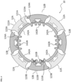
FIG. 4 is a horizontal cross-sectional view of the first and second inner mold segments of the inner mold mechanism in a retracted position. -
Figs. 1 to 4 illustrate aninner mold mechanism 10 for molding an annular structure in accordance with an embodiment of the invention as well as amold 20 featuring such aninner mold mechanism 10. - As can be best seen in
Fig. 3 andFig. 4 , theinner mold mechanism 10 comprises firstinner mold segments 12A and secondinner mold segments 12B arranged circumferentially about the mold axis. The first and secondinner mold segments Fig. 1 andFig. 2 , theinner mold mechanism 10 comprises a first axiallymovable actuator 14A, and a second axiallymovable actuator 14B. Thefirst actuator 14A is mechanically connected to the firstinner mold segments 12A so as to move them radially when it is moved axially itself. Thesecond actuator 14B is mechanically connected to the second inner mold segments so as to move the second inner mold segments radially when it is moved axially. - The
first actuator 14A may include acentral portion 141A and pluralperipheral segment portions 142A (seeFigs. 3 and4 ). Theperipheral segment portions 142A cooperate with the firstinner mold segments 12A. Thecentral portion 141A links theperipheral segment portions 142A to a first axial piston (not shown), which may be controlled hydraulically, pneumatically, or otherwise to move in axial direction. Theperipheral segment portions 142A of thefirst actuator 14A have slanted radially outer surfaces, which cooperate with conjugately slanted radially inner surfaces of the firstinner mold segments 12A. Theperipheral segment portions 142A and the firstinner mold segments 12A may additionally be coupled by a prismatic joint, e.g., comprising a T-shaped groove cooperating with a T-shaped slider. Theinner mold segments 12A are prevented from moving axially, e.g., by first and second sidewall rings 16, 18, but may slide in radial direction. The slanted radially outer surfaces of theperipheral segment portions 142A lie generally on an imaginary right circular cone, the axis of which coincides with the axis of the mold. When thefirst actuator 14A is moved in the direction towards the apex of the cone (downwardly inFig. 1 ), theperipheral segment portions 142A force theinner mold segments 12A to move radially outwardly. Conversely, when thefirst actuator 14A is moved in the direction away from the apex of the cone (upwardly inFig. 1 ), theperipheral segment portions 142A force theinner mold segments 12A to move radially inwardly. - The
second actuator 14B may also include acentral portion 141B and pluralperipheral segment portions 142B, which cooperate with the secondinner mold segments 12B. Thecentral portion 141B links theperipheral segment portions 142B to a second axial piston (not shown), e.g., arranged concentrically with the first axial piston, which may be controlled hydraulically, pneumatically, or otherwise to move in axial direction. Theperipheral segment portions 142B of thesecond actuator 14B have slanted radially outer surfaces, which cooperate with conjugately slanted radially inner surfaces of the secondinner mold segments 12B. Theperipheral segment portions 142B and the secondinner mold segments 12B may additionally be coupled by a prismatic joint, e.g., comprising a T-shaped groove cooperating with a T-shaped slider. Theinner mold segments 12B are prevented from moving axially, e.g., by the first and second sidewall rings 16, 18, but may slide in radial direction. The slanted radially outer surfaces of theperipheral segment portions 142B lie generally on a second imaginary right circular cone, the axis of which coincides with the axis of the mold. When thesecond actuator 14B is moved in the direction towards the apex of the second cone (downwardly inFig. 1 ), theperipheral segment portions 142B force theinner mold segments 12B to move radially outwardly. Conversely, when thesecond actuator 14B is moved in the direction away from the apex of the cone (upwardly inFig. 1 ), theperipheral segment portions 142B force theinner mold segments 12B to move radially inwardly. - The slanted surfaces of the
peripheral segment portions 142B (or the secondinner mold segments 12B) may have the same angle with respect to the axial direction as the slantedperipheral segment portions 142A (or the firstinner mold segments 12A). However, the slant angle may also be different. - The
inner mold mechanism 10 defines radially outward part of themold 20. The radially outward part of themold 20 may be provided by an outer mold ring or by a segmentedouter mold mechanism 22, which may be configured, e.g., like the ones known fromUS 3,779,677 orEP 0 701 894 A2 . - The
inner mold segments outer mold segments 24 delimit themold cavity 26 in radial direction. The first and second sidewall rings 16, 18 delimit themold cavity 26 in the axial direction. The first and second sidewall rings 16, 18 are mounted on first andsecond container plates - The
outer mold segments 24 may be mounted respectively oncarrier segments 32 which are movable radially inwardly and outwardly. Each of thecarrier segments 32 is provided with aninclined surface 34, as well as guiding surfaces (e.g., a T-slot). The respective inclined surfaces cooperate with conjugately inclined surfaces carried by aclosing ring 36. Thecarrier segments 32 are mounted on thecontainer plates carrier segments 32 and theouter mold segments 24 is effected by axial movement of theclosing ring 36. - The inner and outer mold mechanisms are similar in the way they convert axial motion of an actuator into radial motion of the mold segments. However, unlike the
outer mold segments 24, theinner mold segments second actuators inner mold segments 12A separately from the secondinner mold segments 12B. - Each one of the first
inner mold segments 12A comprises a radiallyinner stem 121A and a radially outer front body with an arcedfront surface 122A. The front body hasflanges 123A protruding in azimuthal direction beyond thestem 121A so as to definerecesses 124A between thestem 121A and theflanges 123A. - Each one of the second
inner mold segments 12B comprises a radiallyinner stem 121B and a radially outer front body with an arcedfront surface 122B. The front body of each secondinner mold segment 12B may haveflanges 123B protruding in azimuthal direction beyond thestem 121B so as to define recesses between thestem 121B and theflanges 123B. - The first
inner mold segments 12A may be moved by thefirst actuator 14A between a first retracted position (seeFig. 2 ) and a first deployed position (seeFig. 1 ). Likewise, the secondinner mold segments 12B may be moved by thesecond actuator 14B between a second retracted position (seeFig. 4 ) and a second deployed position (seeFig. 3 ). The first and second deployed positions of the first and secondinner mold segments inner mold segments - When the first
inner mold segments 12A are in the first deployed position and the secondinner mold segments 12B are in the second deployed position, the arcedfront surfaces inner mold segments mold cavity 26. It may be noted that theflanges 123A of the firstinner mold segments 12A and theflanges 123B of the secondinner mold segments 12B are preferably shaped complementarily along their flange edges so as to achieve a tight fit and a substantially smooth radially inner surface of themold cavity 26, when the first and secondinner mold segments - When the first
inner mold segments 12A are in the first retracted position and the secondinner mold segments 12B are in the second retracted position, the second inner mold segments are further retracted than the first inner mold segments (seeFig. 4 ) and the second inner mold segments are lodged at least partially in therecesses 124A of the firstinner mold segments 12A. - It may be worthwhile noting that an inner mold mechanism as proposed herein may greatly facilitate and or improve the curing of annular rubber structures. The inner mold mechanism may, in particular, help to homogeneously apply pressure from the radially interior side of the mold to the item being cured. This is particularly interesting for the curing radially thin annular structures, such as, e.g., shear bands for non-pneumatic tires.
- The annular structure to be cured may be placed around the inner mold mechanism while the mold is open and the
inner mold segments inner mold segments inner mold segments 12A are deployed first by controlling thefirst actuator 14A, then the second inner mold segments are deployed by controlling thesecond actuator 14B. When the mold is closed, the curing of the annular structure may be carried out. After the curing, the mold is opened, theinner mold segments - It should be noted that the movement of the first and second
inner mold segments inner mold segments separate actuators inner mold segments inner mold segments inner mold segments
Claims (12)
- An inner mold mechanism for molding an annular structure such as a tire, the inner mold mechanism comprising: first inner mold segments (12A) and second inner mold segments (12B), the first and second inner mold segments being arranged circumferentially and alternating with each other circumferentially about an axis of the inner mold mechanism; a first axially movable actuator (14A), the first actuator (14A) being mechanically connected to the first inner mold segments (12A) or configured so as to move the first inner mold segments (12A) radially with respect to the axis when the first actuator (14A) is moved axially with respect to the axis; and a second axially movable actuator (14B), the second actuator (14B) being mechanically connected to the second inner mold segments (12B) or configured so as to move the second inner mold segments (12B) radially with respect to the axis when the second actuator (14B) is moved axially with respect to the axis.
- The inner mold mechanism of claim 1, wherein each one of the first inner mold segments (12A) comprises a radially inner stem (121A) and a radially outer front body with an arced front surface (122A), wherein the front body has flanges (112A) protruding in azimuthal direction beyond the stem (121A) so as to define recesses between the stem (121A) and the flanges (112A); and/or wherein each one of the second inner mold segments (12B) comprises a radially inner stem (121B) and a radially outer front body with an arced front surface (122B), wherein the front body has flanges (112B) protruding in azimuthal direction beyond the stem (121B) so as to define recesses between the stem (121B) and the flanges (112B).
- The inner mold mechanism of claim 2, wherein the flanges (112A) of the first inner mold segments and the flanges (112B) of the second inner mold segments are shaped complementarily.
- The inner mold mechanism of at least one of the previous claims, wherein each of the first and each of the second inner mold segments (12A, 12B) is mechanically constrained from moving into the axial direction.
- The inner mold mechanism of at least one of the previous claims, wherein the first actuator (14A) is connected to the first inner mold segments (12A) by respective one or more first prismatic joints and/or comprises one or more T-shaped sliders cooperating with respective one or more T-shaped grooves, and wherein the second actuator (14B) is connected to the second inner mold segments (12B) by respective one or more second prismatic joints and/or comprises one or more T-shaped sliders cooperating with respective one or more T-shaped grooves.
- The inner mold mechanism of at least one of the previous claims, wherein the first inner mold segments (12A) are movable between a first retracted position and a first deployed position, wherein the second inner mold segments (12B) are movable between a second retracted position and a second deployed position, wherein, when the first inner mold segments (12A) are in the first deployed position and the second inner mold segments (12B) are in the second deployed position, the first and second inner mold segments (12A, 12B) form together a substantially continuous inner mold surface.
- The inner mold mechanism of claim 6, wherein the first inner mold segments (12A) have sides with recesses therein and wherein, when the first inner mold segments are in the first retracted position and the second inner mold segments (12B) are in the second retracted position, the second inner mold segments (12B) are further retracted than the first inner mold segments (12A) and the second inner mold segments (12B) are lodged at least partially in the recesses in the sides of the first inner mold segments (12A).
- The inner mold mechanism of at least one of the previous claims comprising from three to five first inner mold segments (12A) and the same number of second inner mold segments (12B).
- An inner mold mechanism for molding an annular tire structure, the inner mold mechanism comprising: first inner mold segments (12A) and second inner mold segments (12A) arranged around a mold axis, the first and second inner mold segments (12A, 12B) alternating with each other in circumferential direction about the mold axis, each of the first and each of the second inner mold segments (12A, 12B) being constrained to one linear degree of freedom in radial direction with respect to the mold axis; at least one axially movable actuator (14A, 14B), the at least one axially movable actuator being mechanically connected to the first inner mold segments (12A), the second inner mold segments (12B) or both the first and the second inner mold segments (12A, 12B) or configured so as to move the first inner mold segments, the second inner mold segments or both the first and the second inner mold segments radially when the at least one axially movable actuator (14A, 14B) is moved axially; wherein each one of the first inner mold segments (12A) comprises a radially inner stem (121A) and a radially outer front body with an arced front surface (122A), wherein the front body has flanges (123A) protruding in circumferential direction beyond the stem (121A) so as to define recesses between the stem (121A) and the flanges (123A); wherein each one of the second inner mold segments (12B) comprises a radially outer front body with an arced front surface (122B); wherein the first inner mold segments (12A) are movable by the at least one axially movable actuator (14A) between a first retracted position and a first deployed position; wherein the second inner mold segments (12B) are movable by the at least one axially movable actuator (14A) between a second retracted position and a second deployed position; wherein, when the first inner mold segments (12A) are in the first deployed position and the second inner mold segments (12C) are in the second deployed position, the arced front surfaces (122A, 122B) of the first and second inner mold segments (12A, 12B) form together an annular inner mold surface; and wherein, when the first inner mold segments (12A) are in the first retracted position and the second inner mold segments (12B) are in the second retracted position, the second inner mold segments (12B) are further retracted than the first inner mold segments (12A) and the second inner mold segments are lodged at least partially in the recesses of the first inner mold segments.
- The inner mold mechanism as claimed in claim 9, comprising from three to five first inner mold segments (12A) and the same number of second inner mold segments (12B).
- The inner mold mechanism as claimed in claim 9 or 10, wherein the at least one axially movable actuator comprises a first axially movable actuator (14A) and a second axially movable actuator (14B), the first actuator (14A) being mechanically connected to the first inner mold segments (12A) or configured so as to move the first inner mold segments (12A) radially with respect to the axis when the first actuator (14A) is moved axially with respect to the axis; a second axially movable actuator (14B), the second actuator (14B) being mechanically connected to the second inner mold segments (12B) or configured so as to move the second inner mold segments (12B) radially with respect to the axis when the second actuator (14B) is moved axially with respect to the axis.
- A mold for curing an annular tire structure, the mold (20) comprising an outer mold mechanism and an inner mold mechanism (10), the outer and inner mold mechanisms defining there between an openable and closable mold cavity for accommodating therein an annular tire structure to be cured, wherein the inner mold mechanism (10) is an inner mold mechanism (10) in accordance with one of the previous claims.
Applications Claiming Priority (1)
| Application Number | Priority Date | Filing Date | Title |
|---|---|---|---|
| US18/060,034 US20240173931A1 (en) | 2022-11-30 | 2022-11-30 | Mold for producing annular rubber component |
Publications (2)
| Publication Number | Publication Date |
|---|---|
| EP4378675A1 true EP4378675A1 (en) | 2024-06-05 |
| EP4378675B1 EP4378675B1 (en) | 2025-10-01 |
Family
ID=88969543
Family Applications (1)
| Application Number | Title | Priority Date | Filing Date |
|---|---|---|---|
| EP23212117.8A Active EP4378675B1 (en) | 2022-11-30 | 2023-11-24 | Mold for producing annular rubber component |
Country Status (3)
| Country | Link |
|---|---|
| US (1) | US20240173931A1 (en) |
| EP (1) | EP4378675B1 (en) |
| JP (1) | JP2024079616A (en) |
Families Citing this family (4)
| Publication number | Priority date | Publication date | Assignee | Title |
|---|---|---|---|---|
| DE102020212547A1 (en) * | 2020-10-05 | 2022-04-07 | Continental Reifen Deutschland Gmbh | Curing press and method for vulcanizing a vehicle tire in this curing press under vacuum |
| DE102020212550A1 (en) * | 2020-10-05 | 2022-04-07 | Continental Reifen Deutschland Gmbh | Curing press and method for vulcanizing a vehicle tire in this curing press under vacuum |
| DE102020212548A1 (en) * | 2020-10-05 | 2022-04-07 | Continental Reifen Deutschland Gmbh | Curing press and method for vulcanizing a vehicle tire in this curing press under vacuum |
| DE102020212551A1 (en) * | 2020-10-05 | 2022-04-07 | Continental Reifen Deutschland Gmbh | Curing press and method for vulcanizing a vehicle tire in this curing press under vacuum |
Citations (9)
| Publication number | Priority date | Publication date | Assignee | Title |
|---|---|---|---|---|
| GB830231A (en) | 1957-02-15 | 1960-03-09 | Cementation Co Ltd | Improvements in apparatus for removing material from shafts sunk into the ground |
| US3779677A (en) | 1971-09-27 | 1973-12-18 | Goodyear Tire & Rubber | Segmented tire mold |
| US3867504A (en) | 1971-09-27 | 1975-02-18 | Goodyear Tire & Rubber | Method of operating a fire mold |
| US4207052A (en) * | 1976-07-16 | 1980-06-10 | Caterpillar Tractor Co. | Curing mold for curing replaceable tread and track belts |
| US4957656A (en) | 1988-09-14 | 1990-09-18 | Molecular Biosystems, Inc. | Continuous sonication method for preparing protein encapsulated microbubbles |
| JPH07144375A (en) * | 1993-11-22 | 1995-06-06 | Sumitomo Rubber Ind Ltd | Tire band winding equipment |
| EP0701894A2 (en) | 1994-07-20 | 1996-03-20 | The Goodyear Tire & Rubber Company | Ventless segmented tyre mould and method for vulcanizing tyres using such a mould |
| EP1520674A2 (en) * | 2003-10-03 | 2005-04-06 | The Goodyear Tire & Rubber Company | A mold and method of molding annular tread belt |
| CN107972234A (en) | 2017-11-27 | 2018-05-01 | 巨轮智能装备股份有限公司 | A kind of injecting molding die of solid tyre and its method for producing solid tyre |
-
2022
- 2022-11-30 US US18/060,034 patent/US20240173931A1/en not_active Abandoned
-
2023
- 2023-11-21 JP JP2023197077A patent/JP2024079616A/en active Pending
- 2023-11-24 EP EP23212117.8A patent/EP4378675B1/en active Active
Patent Citations (10)
| Publication number | Priority date | Publication date | Assignee | Title |
|---|---|---|---|---|
| GB830231A (en) | 1957-02-15 | 1960-03-09 | Cementation Co Ltd | Improvements in apparatus for removing material from shafts sunk into the ground |
| US3779677A (en) | 1971-09-27 | 1973-12-18 | Goodyear Tire & Rubber | Segmented tire mold |
| US3867504A (en) | 1971-09-27 | 1975-02-18 | Goodyear Tire & Rubber | Method of operating a fire mold |
| US4207052A (en) * | 1976-07-16 | 1980-06-10 | Caterpillar Tractor Co. | Curing mold for curing replaceable tread and track belts |
| US4957656A (en) | 1988-09-14 | 1990-09-18 | Molecular Biosystems, Inc. | Continuous sonication method for preparing protein encapsulated microbubbles |
| JPH07144375A (en) * | 1993-11-22 | 1995-06-06 | Sumitomo Rubber Ind Ltd | Tire band winding equipment |
| EP0701894A2 (en) | 1994-07-20 | 1996-03-20 | The Goodyear Tire & Rubber Company | Ventless segmented tyre mould and method for vulcanizing tyres using such a mould |
| US5585064A (en) | 1994-07-20 | 1996-12-17 | The Goodyear Tire & Rubber Company | Ventless segmented tire mold and method therefore |
| EP1520674A2 (en) * | 2003-10-03 | 2005-04-06 | The Goodyear Tire & Rubber Company | A mold and method of molding annular tread belt |
| CN107972234A (en) | 2017-11-27 | 2018-05-01 | 巨轮智能装备股份有限公司 | A kind of injecting molding die of solid tyre and its method for producing solid tyre |
Also Published As
| Publication number | Publication date |
|---|---|
| JP2024079616A (en) | 2024-06-11 |
| EP4378675B1 (en) | 2025-10-01 |
| US20240173931A1 (en) | 2024-05-30 |
Similar Documents
| Publication | Publication Date | Title |
|---|---|---|
| EP4378675B1 (en) | Mold for producing annular rubber component | |
| US4081310A (en) | Bead grip ring | |
| KR920003078B1 (en) | Bladderless Tire Forming Equipment | |
| CN1076660C (en) | Tire assembling and vulcanization | |
| US20040207116A1 (en) | Method for curing tires and a self-locking tire mold | |
| US9724884B2 (en) | Equipment for moulding and curing a green tyre | |
| CN107639866B (en) | Center mechanism for tire building drum | |
| US4758401A (en) | Method for vulcanizing pneumatic vehicle tires | |
| KR100538312B1 (en) | A tyre air tube and related manufaturing process | |
| CA1313115C (en) | Heavy duty radial tire | |
| CN101541519B (en) | Process and apparatus for manufacturing tyres | |
| EP1601521B1 (en) | A method and an apparatus for manufacturing tyres for vehicle wheels | |
| CA1149273A (en) | Tire building machine | |
| CN101541518B (en) | Apparatus for vulcanization and moulding of vehicles tyres | |
| CN111469460B (en) | Tyre building drum | |
| JP4363521B2 (en) | Pneumatic radial tire molding and vulcanizing bladder unit | |
| US20050073074A1 (en) | Mold and method of molding annular tread belt | |
| US4181483A (en) | Apparatus for the bellowless vulcanization of tire blanks | |
| EP0509095B1 (en) | Green tire building apparatus | |
| JP6933929B2 (en) | Central deck assembly for tire assembly drums | |
| EP4438282A1 (en) | Segmented curing ring and tire mold for npt elastomer bands and method for curing a green elastomer band | |
| EP3658365B1 (en) | Apparatus for building a tyre for vehicle wheels | |
| JP7410702B2 (en) | Tire curing mold | |
| JP4367927B2 (en) | Method and apparatus for mounting a bladder unit device for forming and vulcanizing a pneumatic radial tire | |
| JP2004050897A (en) | Pneumatic tire for passenger car |
Legal Events
| Date | Code | Title | Description |
|---|---|---|---|
| PUAI | Public reference made under article 153(3) epc to a published international application that has entered the european phase |
Free format text: ORIGINAL CODE: 0009012 |
|
| STAA | Information on the status of an ep patent application or granted ep patent |
Free format text: STATUS: THE APPLICATION HAS BEEN PUBLISHED |
|
| AK | Designated contracting states |
Kind code of ref document: A1 Designated state(s): AL AT BE BG CH CY CZ DE DK EE ES FI FR GB GR HR HU IE IS IT LI LT LU LV MC ME MK MT NL NO PL PT RO RS SE SI SK SM TR |
|
| STAA | Information on the status of an ep patent application or granted ep patent |
Free format text: STATUS: REQUEST FOR EXAMINATION WAS MADE |
|
| 17P | Request for examination filed |
Effective date: 20241119 |
|
| RBV | Designated contracting states (corrected) |
Designated state(s): AL AT BE BG CH CY CZ DE DK EE ES FI FR GB GR HR HU IE IS IT LI LT LU LV MC ME MK MT NL NO PL PT RO RS SE SI SK SM TR |
|
| GRAP | Despatch of communication of intention to grant a patent |
Free format text: ORIGINAL CODE: EPIDOSNIGR1 |
|
| STAA | Information on the status of an ep patent application or granted ep patent |
Free format text: STATUS: GRANT OF PATENT IS INTENDED |
|
| INTG | Intention to grant announced |
Effective date: 20250428 |
|
| GRAS | Grant fee paid |
Free format text: ORIGINAL CODE: EPIDOSNIGR3 |
|
| GRAA | (expected) grant |
Free format text: ORIGINAL CODE: 0009210 |
|
| STAA | Information on the status of an ep patent application or granted ep patent |
Free format text: STATUS: THE PATENT HAS BEEN GRANTED |
|
| AK | Designated contracting states |
Kind code of ref document: B1 Designated state(s): AL AT BE BG CH CY CZ DE DK EE ES FI FR GB GR HR HU IE IS IT LI LT LU LV MC ME MK MT NL NO PL PT RO RS SE SI SK SM TR |
|
| REG | Reference to a national code |
Ref country code: GB Ref legal event code: FG4D Ref country code: CH Ref legal event code: F10 Free format text: ST27 STATUS EVENT CODE: U-0-0-F10-F00 (AS PROVIDED BY THE NATIONAL OFFICE) Effective date: 20251001 |
|
| REG | Reference to a national code |
Ref country code: IE Ref legal event code: FG4D |
|
| REG | Reference to a national code |
Ref country code: DE Ref legal event code: R096 Ref document number: 602023007137 Country of ref document: DE |
|
| PGFP | Annual fee paid to national office [announced via postgrant information from national office to epo] |
Ref country code: DE Payment date: 20251022 Year of fee payment: 3 |
|
| PGFP | Annual fee paid to national office [announced via postgrant information from national office to epo] |
Ref country code: AT Payment date: 20260113 Year of fee payment: 3 |
|
| PGFP | Annual fee paid to national office [announced via postgrant information from national office to epo] |
Ref country code: FR Payment date: 20251119 Year of fee payment: 3 |
|
| REG | Reference to a national code |
Ref country code: NL Ref legal event code: MP Effective date: 20251001 |
|
| REG | Reference to a national code |
Ref country code: AT Ref legal event code: MK05 Ref document number: 1842127 Country of ref document: AT Kind code of ref document: T Effective date: 20251001 |
|
| PG25 | Lapsed in a contracting state [announced via postgrant information from national office to epo] |
Ref country code: NL Free format text: LAPSE BECAUSE OF FAILURE TO SUBMIT A TRANSLATION OF THE DESCRIPTION OR TO PAY THE FEE WITHIN THE PRESCRIBED TIME-LIMIT Effective date: 20251001 |
|
| PG25 | Lapsed in a contracting state [announced via postgrant information from national office to epo] |
Ref country code: ES Free format text: LAPSE BECAUSE OF FAILURE TO SUBMIT A TRANSLATION OF THE DESCRIPTION OR TO PAY THE FEE WITHIN THE PRESCRIBED TIME-LIMIT Effective date: 20251001 |
|
| REG | Reference to a national code |
Ref country code: LT Ref legal event code: MG9D |
|
| PG25 | Lapsed in a contracting state [announced via postgrant information from national office to epo] |
Ref country code: NO Free format text: LAPSE BECAUSE OF FAILURE TO SUBMIT A TRANSLATION OF THE DESCRIPTION OR TO PAY THE FEE WITHIN THE PRESCRIBED TIME-LIMIT Effective date: 20260101 |
|
| PG25 | Lapsed in a contracting state [announced via postgrant information from national office to epo] |
Ref country code: FI Free format text: LAPSE BECAUSE OF FAILURE TO SUBMIT A TRANSLATION OF THE DESCRIPTION OR TO PAY THE FEE WITHIN THE PRESCRIBED TIME-LIMIT Effective date: 20251001 Ref country code: AT Free format text: LAPSE BECAUSE OF FAILURE TO SUBMIT A TRANSLATION OF THE DESCRIPTION OR TO PAY THE FEE WITHIN THE PRESCRIBED TIME-LIMIT Effective date: 20251001 Ref country code: HR Free format text: LAPSE BECAUSE OF FAILURE TO SUBMIT A TRANSLATION OF THE DESCRIPTION OR TO PAY THE FEE WITHIN THE PRESCRIBED TIME-LIMIT Effective date: 20251001 |
|
| PG25 | Lapsed in a contracting state [announced via postgrant information from national office to epo] |
Ref country code: RS Free format text: LAPSE BECAUSE OF FAILURE TO SUBMIT A TRANSLATION OF THE DESCRIPTION OR TO PAY THE FEE WITHIN THE PRESCRIBED TIME-LIMIT Effective date: 20260101 |
|
| PG25 | Lapsed in a contracting state [announced via postgrant information from national office to epo] |
Ref country code: IS Free format text: LAPSE BECAUSE OF FAILURE TO SUBMIT A TRANSLATION OF THE DESCRIPTION OR TO PAY THE FEE WITHIN THE PRESCRIBED TIME-LIMIT Effective date: 20260201 |
|
| PG25 | Lapsed in a contracting state [announced via postgrant information from national office to epo] |
Ref country code: PT Free format text: LAPSE BECAUSE OF FAILURE TO SUBMIT A TRANSLATION OF THE DESCRIPTION OR TO PAY THE FEE WITHIN THE PRESCRIBED TIME-LIMIT Effective date: 20260202 Ref country code: CZ Free format text: LAPSE BECAUSE OF FAILURE TO SUBMIT A TRANSLATION OF THE DESCRIPTION OR TO PAY THE FEE WITHIN THE PRESCRIBED TIME-LIMIT Effective date: 20251001 |
|
| PG25 | Lapsed in a contracting state [announced via postgrant information from national office to epo] |
Ref country code: PL Free format text: LAPSE BECAUSE OF FAILURE TO SUBMIT A TRANSLATION OF THE DESCRIPTION OR TO PAY THE FEE WITHIN THE PRESCRIBED TIME-LIMIT Effective date: 20251001 |
|
| PG25 | Lapsed in a contracting state [announced via postgrant information from national office to epo] |
Ref country code: LV Free format text: LAPSE BECAUSE OF FAILURE TO SUBMIT A TRANSLATION OF THE DESCRIPTION OR TO PAY THE FEE WITHIN THE PRESCRIBED TIME-LIMIT Effective date: 20251001 |
|
| PG25 | Lapsed in a contracting state [announced via postgrant information from national office to epo] |
Ref country code: BG Free format text: LAPSE BECAUSE OF FAILURE TO SUBMIT A TRANSLATION OF THE DESCRIPTION OR TO PAY THE FEE WITHIN THE PRESCRIBED TIME-LIMIT Effective date: 20251001 |
|
| PG25 | Lapsed in a contracting state [announced via postgrant information from national office to epo] |
Ref country code: RO Free format text: LAPSE BECAUSE OF FAILURE TO SUBMIT A TRANSLATION OF THE DESCRIPTION OR TO PAY THE FEE WITHIN THE PRESCRIBED TIME-LIMIT Effective date: 20251001 |
|
| PG25 | Lapsed in a contracting state [announced via postgrant information from national office to epo] |
Ref country code: LT Free format text: LAPSE BECAUSE OF FAILURE TO SUBMIT A TRANSLATION OF THE DESCRIPTION OR TO PAY THE FEE WITHIN THE PRESCRIBED TIME-LIMIT Effective date: 20251001 |
|
| PG25 | Lapsed in a contracting state [announced via postgrant information from national office to epo] |
Ref country code: MC Free format text: LAPSE BECAUSE OF FAILURE TO SUBMIT A TRANSLATION OF THE DESCRIPTION OR TO PAY THE FEE WITHIN THE PRESCRIBED TIME-LIMIT Effective date: 20251001 |
|
| REG | Reference to a national code |
Ref country code: DE Ref legal event code: R097 Ref document number: 602023007137 Country of ref document: DE |
|
| PG25 | Lapsed in a contracting state [announced via postgrant information from national office to epo] |
Ref country code: SM Free format text: LAPSE BECAUSE OF FAILURE TO SUBMIT A TRANSLATION OF THE DESCRIPTION OR TO PAY THE FEE WITHIN THE PRESCRIBED TIME-LIMIT Effective date: 20251001 |
|
| PG25 | Lapsed in a contracting state [announced via postgrant information from national office to epo] |
Ref country code: DK Free format text: LAPSE BECAUSE OF FAILURE TO SUBMIT A TRANSLATION OF THE DESCRIPTION OR TO PAY THE FEE WITHIN THE PRESCRIBED TIME-LIMIT Effective date: 20251001 |
|
| PG25 | Lapsed in a contracting state [announced via postgrant information from national office to epo] |
Ref country code: IT Free format text: LAPSE BECAUSE OF FAILURE TO SUBMIT A TRANSLATION OF THE DESCRIPTION OR TO PAY THE FEE WITHIN THE PRESCRIBED TIME-LIMIT Effective date: 20251001 |
|
| PG25 | Lapsed in a contracting state [announced via postgrant information from national office to epo] |
Ref country code: LU Free format text: LAPSE BECAUSE OF NON-PAYMENT OF DUE FEES Effective date: 20251124 |
|
| PG25 | Lapsed in a contracting state [announced via postgrant information from national office to epo] |
Ref country code: EE Free format text: LAPSE BECAUSE OF FAILURE TO SUBMIT A TRANSLATION OF THE DESCRIPTION OR TO PAY THE FEE WITHIN THE PRESCRIBED TIME-LIMIT Effective date: 20251001 |
|
| PG25 | Lapsed in a contracting state [announced via postgrant information from national office to epo] |
Ref country code: SK Free format text: LAPSE BECAUSE OF FAILURE TO SUBMIT A TRANSLATION OF THE DESCRIPTION OR TO PAY THE FEE WITHIN THE PRESCRIBED TIME-LIMIT Effective date: 20251001 |
|
| PG25 | Lapsed in a contracting state [announced via postgrant information from national office to epo] |
Ref country code: SE Free format text: LAPSE BECAUSE OF FAILURE TO SUBMIT A TRANSLATION OF THE DESCRIPTION OR TO PAY THE FEE WITHIN THE PRESCRIBED TIME-LIMIT Effective date: 20251001 |
|
| PLBE | No opposition filed within time limit |
Free format text: ORIGINAL CODE: 0009261 |
|
| STAA | Information on the status of an ep patent application or granted ep patent |
Free format text: STATUS: NO OPPOSITION FILED WITHIN TIME LIMIT |
|
| REG | Reference to a national code |
Ref country code: CH Ref legal event code: L10 Free format text: ST27 STATUS EVENT CODE: U-0-0-L10-L00 (AS PROVIDED BY THE NATIONAL OFFICE) Effective date: 20260812 |