EP4378620A1 - Welding machine - Google Patents
Welding machine Download PDFInfo
- Publication number
- EP4378620A1 EP4378620A1 EP23835895.6A EP23835895A EP4378620A1 EP 4378620 A1 EP4378620 A1 EP 4378620A1 EP 23835895 A EP23835895 A EP 23835895A EP 4378620 A1 EP4378620 A1 EP 4378620A1
- Authority
- EP
- European Patent Office
- Prior art keywords
- welding
- welding device
- present disclosure
- processor
- scanner
- Prior art date
- Legal status (The legal status is an assumption and is not a legal conclusion. Google has not performed a legal analysis and makes no representation as to the accuracy of the status listed.)
- Pending
Links
Images






Classifications
-
- B—PERFORMING OPERATIONS; TRANSPORTING
- B23—MACHINE TOOLS; METAL-WORKING NOT OTHERWISE PROVIDED FOR
- B23K—SOLDERING OR UNSOLDERING; WELDING; CLADDING OR PLATING BY SOLDERING OR WELDING; CUTTING BY APPLYING HEAT LOCALLY, e.g. FLAME CUTTING; WORKING BY LASER BEAM
- B23K26/00—Working by laser beam, e.g. welding, cutting or boring
- B23K26/08—Devices involving relative movement between laser beam and workpiece
- B23K26/082—Scanning systems, i.e. devices involving movement of the laser beam relative to the laser head
-
- B—PERFORMING OPERATIONS; TRANSPORTING
- B23—MACHINE TOOLS; METAL-WORKING NOT OTHERWISE PROVIDED FOR
- B23K—SOLDERING OR UNSOLDERING; WELDING; CLADDING OR PLATING BY SOLDERING OR WELDING; CUTTING BY APPLYING HEAT LOCALLY, e.g. FLAME CUTTING; WORKING BY LASER BEAM
- B23K26/00—Working by laser beam, e.g. welding, cutting or boring
- B23K26/02—Positioning or observing the workpiece, e.g. with respect to the point of impact; Aligning, aiming or focusing the laser beam
- B23K26/04—Automatically aligning, aiming or focusing the laser beam, e.g. using the back-scattered light
- B23K26/044—Seam tracking
-
- B—PERFORMING OPERATIONS; TRANSPORTING
- B23—MACHINE TOOLS; METAL-WORKING NOT OTHERWISE PROVIDED FOR
- B23K—SOLDERING OR UNSOLDERING; WELDING; CLADDING OR PLATING BY SOLDERING OR WELDING; CUTTING BY APPLYING HEAT LOCALLY, e.g. FLAME CUTTING; WORKING BY LASER BEAM
- B23K26/00—Working by laser beam, e.g. welding, cutting or boring
- B23K26/20—Bonding
- B23K26/21—Bonding by welding
- B23K26/24—Seam welding
- B23K26/26—Seam welding of rectilinear seams
-
- B—PERFORMING OPERATIONS; TRANSPORTING
- B23—MACHINE TOOLS; METAL-WORKING NOT OTHERWISE PROVIDED FOR
- B23K—SOLDERING OR UNSOLDERING; WELDING; CLADDING OR PLATING BY SOLDERING OR WELDING; CUTTING BY APPLYING HEAT LOCALLY, e.g. FLAME CUTTING; WORKING BY LASER BEAM
- B23K31/00—Processes relevant to this subclass, specially adapted for particular articles or purposes, but not covered by any single one of main groups B23K1/00 - B23K28/00
- B23K31/12—Processes relevant to this subclass, specially adapted for particular articles or purposes, but not covered by any single one of main groups B23K1/00 - B23K28/00 relating to investigating the properties, e.g. the weldability, of materials
- B23K31/125—Weld quality monitoring
-
- H—ELECTRICITY
- H01—ELECTRIC ELEMENTS
- H01M—PROCESSES OR MEANS, e.g. BATTERIES, FOR THE DIRECT CONVERSION OF CHEMICAL ENERGY INTO ELECTRICAL ENERGY
- H01M50/00—Constructional details or processes of manufacture of the non-active parts of electrochemical cells other than fuel cells, e.g. hybrid cells
- H01M50/20—Mountings; Secondary casings or frames; Racks, modules or packs; Suspension devices; Shock absorbers; Transport or carrying devices; Holders
- H01M50/204—Racks, modules or packs for multiple batteries or multiple cells
- H01M50/207—Racks, modules or packs for multiple batteries or multiple cells characterised by their shape
- H01M50/209—Racks, modules or packs for multiple batteries or multiple cells characterised by their shape adapted for prismatic or rectangular cells
-
- H—ELECTRICITY
- H01—ELECTRIC ELEMENTS
- H01M—PROCESSES OR MEANS, e.g. BATTERIES, FOR THE DIRECT CONVERSION OF CHEMICAL ENERGY INTO ELECTRICAL ENERGY
- H01M50/00—Constructional details or processes of manufacture of the non-active parts of electrochemical cells other than fuel cells, e.g. hybrid cells
- H01M50/50—Current conducting connections for cells or batteries
- H01M50/502—Interconnectors for connecting terminals of adjacent batteries; Interconnectors for connecting cells outside a battery casing
- H01M50/514—Methods for interconnecting adjacent batteries or cells
- H01M50/516—Methods for interconnecting adjacent batteries or cells by welding, soldering or brazing
-
- B—PERFORMING OPERATIONS; TRANSPORTING
- B23—MACHINE TOOLS; METAL-WORKING NOT OTHERWISE PROVIDED FOR
- B23K—SOLDERING OR UNSOLDERING; WELDING; CLADDING OR PLATING BY SOLDERING OR WELDING; CUTTING BY APPLYING HEAT LOCALLY, e.g. FLAME CUTTING; WORKING BY LASER BEAM
- B23K2101/00—Articles made by soldering, welding or cutting
- B23K2101/36—Electric or electronic devices
- B23K2101/38—Conductors
-
- Y—GENERAL TAGGING OF NEW TECHNOLOGICAL DEVELOPMENTS; GENERAL TAGGING OF CROSS-SECTIONAL TECHNOLOGIES SPANNING OVER SEVERAL SECTIONS OF THE IPC; TECHNICAL SUBJECTS COVERED BY FORMER USPC CROSS-REFERENCE ART COLLECTIONS [XRACs] AND DIGESTS
- Y02—TECHNOLOGIES OR APPLICATIONS FOR MITIGATION OR ADAPTATION AGAINST CLIMATE CHANGE
- Y02E—REDUCTION OF GREENHOUSE GAS [GHG] EMISSIONS, RELATED TO ENERGY GENERATION, TRANSMISSION OR DISTRIBUTION
- Y02E60/00—Enabling technologies; Technologies with a potential or indirect contribution to GHG emissions mitigation
- Y02E60/10—Energy storage using batteries
Definitions
- the present disclosure relates to a welding device.
- Welding technology is widely used in various industrial fields. For example, in the battery field, welding technology is applied to welding between battery module cases or between leads and bus bars.
- Welding is the coupling of two or more members or parts, and it is necessary to secure a certain level or higher of welding quality so that the coupling state may be maintained reliably.
- welding quality is often not secured stably.
- the electrode leads of battery cells and bus bars may be coupled by laser welding.
- the frame and end plate of a battery module or a battery module case may be coupled by laser welding. In this case, if the welding object is not placed precisely on the welding device or is misaligned, the welding work line may be deviated. Therefore, it is necessary to increase the accuracy of welding by appropriately calibrating or updating the welding work line before welding.
- the present disclosure is designed to solve the above-described problems and other problems.
- an object of the present disclosure may be to provide a welding device capable of increasing welding accuracy.
- Another object of the present disclosure may be to provide a welding device capable of inspecting welding quality in real time while welding is in progress.
- a welding device for welding a plurality of materials arranged to be in contact, and may include a scanner configured to deflect light; a welding laser configured to emit light toward the scanner; a galvo module configured to deflect light toward the scanner; a scan laser configured to emit light toward the galvo module; and a processor configured to control at least one of the scanner and the galvo module to scan boundaries of the plurality of materials.
- the processor may be configured to measure a distance between the focus at which the scanner is aimed and the scanner.
- the processor may calibrate the preset welding work line based on coordinate information obtained by scanning the boundaries of the plurality of materials.
- the processor may be configured to control the welding laser and the scanner to form a keyhole, and to control the scan laser and the galvo module to scan around the keyhole.
- At least one of the plurality of materials may be a frame of a battery module.
- the plurality of materials may include a first material; and a second material laminated on the first material and exposing a portion of the upper surface of the first material, wherein the welding device may further include a jig that brings the second material into close contact with the first material.
- the first material may be a bus bar
- the second material may be an electrode lead of a battery cell
- the jig may be configured to press the electrode lead, and a hole may be formed to penetrate in a vertical direction, wherein the hole may be configured to expose at least a portion of the electrode lead and at least a portion of the bus bar.
- the processor may be configured to calibrate the preset welding work line based on coordinate information obtained by scanning the boundary of the bus bar and the electrode lead.
- the jig may include a first part pressing the electrode lead; and a second part facing the first part.
- the processor may calibrate the preset welding work line based on coordinate information obtained by scanning the first part and the second part.
- a battery cell according to the present disclosure is welded through the welding device of the present disclosure.
- a battery module according to the present disclosure is welded through the welding device of the present disclosure.
- a battery cell manufacturing device includes the welding device according to the present disclosure.
- a battery module manufacturing device includes the welding device according to the present disclosure.
- a welding method according to the present disclosure uses the welding device according to the present disclosure.
- welding accuracy may be improved.
- welding accuracy may be improved by appropriately calibrating or updating the welding work line even if the welding object is misaligned.
- welding defects may be quickly and accurately sensed.
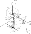
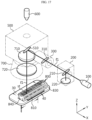
- FIG. 1 is a view showing a partial configuration of a welding device according to an embodiment of the present disclosure.
- FIG. 2 is a view schematically showing an optical configuration of a welding device according to an embodiment of the present disclosure.
- a welding device according to an embodiment of the present disclosure is a welding device for welding a plurality of materials 60 arranged to be in contact.
- the welding device according to an embodiment of the present disclosure may include a scanner 500, a welding laser 600, a galvo module 300, a scan laser 100, and a processor 400.
- the plurality of materials 60 may be disposed to be in contact for butt welding, edge welding, fringe welding, or overlap welding.
- the meaning of contact refers to the positional relationship of the plurality of materials 60 for welding, and the type of welding joint is not limited.
- the scanner 500 may be configured to deflect light.
- the scanner 500 may include a scan mirror 510 therein.
- the scan mirror 510 may deflect light incident on the scanner 500.
- the scan mirror 510 may be configured to be rotatable.
- the scan mirror 510 may be configured to deflect light in various directions.
- the welding laser 600 may output light 12.
- the welding laser 600 may emit light 12 toward the scanner 500.
- the light 12 emitted by the welding laser 600 may have an intensity high enough to weld the plurality of materials 60.
- the galvo module 300 may be configured to deflect light.
- the galvo module 300 may include a galvo mirror 310 therein.
- the galvo mirror 310 may deflect light incident on the galvo module 300.
- the galvo mirror 310 may be configured to be rotatable.
- the galvo mirror 310 may be configured to deflect light in various directions.
- the galvo module 300 may be configured to deflect the incident light toward the scanner 500.
- the galvo module 300 may be configured to be fastened, coupled, fixed, or assembled to one side of the scanner 500.
- the scan laser 100 may output light 11.
- the scan laser 100 may emit light 11 toward the galvo module 300.
- the light 11 emitted by the scan laser 100 may have a weaker intensity than the light 12 emitted by the welding laser 600.
- the scan laser 100 may output light 11 having a wavelength different from that of the welding laser 600.
- the scan laser 100 may output visible light.
- the scan laser 100 may output light 11 for scanning the shape, location, surface, or boundary of the plurality of materials 60.
- the scan laser 100 may be configured to scan around the focus of the light 12 emitted by the welding laser 600.
- the processor 400 may be configured to include a first control computer 410 and a second control computer 420.
- the first control computer 410 may be physically, electrically, or optically connected to at least one of the scanner 500, the welding laser 600, the scan laser 100, or the galvo module 300.
- the first control computer 410 may be configured to monitor or control at least one of the scanner 500, the welding laser 600, the scan laser 100, or the galvo module 300.
- the second control computer 420 may be physically, electrically, or optically connected to the first control computer 410.
- the second control computer 420 may be configured to monitor or control the first control computer 410.
- the second control computer 420 may include an interface unit capable of receiving commands from a user.
- the processor 400 may be used to refer to the first control computer 410 and the second control computer 420.
- the processor 400 may be configured to scan the boundaries of the plurality of materials 60 by controlling at least one of the scanner 500 and the galvo module 300. In this case, the processor 400 may turn off the output of the welding laser 600 and turn on the output of the scan laser 100. The processor 400 may scan the boundaries of the plurality of materials 60 before welding the plurality of materials 60.
- the processor 400 may scan, detect, sense, or recognize a welding work line before welding.
- the processor 400 may perform a more sophisticated welding operation by scanning the boundaries of the plurality of materials 60.
- the welding device may be configured to further include an optical module 200 or a condensing module 700.
- the scan laser 100 may be configured to emit light 11 toward the optical module 200.
- the optical module 200 may output, deflect, or pass at least a portion of the incident light toward the galvo module 300.
- the optical module 200 may be configured to include a beam splitter 210, a reference mirror 220, and a detector (not shown).
- the beam splitter 210 may output, deflect, or pass at least a portion of the light incident on the optical module 200 toward the galvo mirror 310.
- the beam splitter 210 may output, deflect, or pass at least a portion of the light incident on the optical module 200 toward the reference mirror 220.
- the reference mirror 220 may be configured to reflect the incident light toward the detector.
- the processor 400 may be configured to acquire optical coherence tomography (OCT) through the optical module 200.
- OCT optical coherence tomography
- the condensing module 700 may be configured to be fastened, coupled, fixed, or assembled to one side of the scanner 500.
- the condensing module 700 may be configured to include a first condensing lens 710 and a second condensing lens 720.
- the condensing module 700 may be configured to focus light deflected by the scanner 500 toward a plurality of materials.
- the light 12 output from the welding laser 600 and the light 11 output from the scan laser 100 may be focused on the plurality of materials 60 through the condensing module 700.
- FIG. 3 is an exploded view showing a partial configuration of a battery module 50 welded by a welding device according to an embodiment of the present disclosure.
- FIG. 4 is a perspective view showing the battery module 50 of FIG. 3 .
- a battery module 50 welded by a welding device may be configured to include a frame 51, an end plate 52, and a plurality of cells 53.
- the end plate 52 may be fastened, coupled, or fixed to the frame 51 on the front side and the rear side, respectively.
- the end plate 52 and the frame 51 may be coupled through welding.
- a welding line wb or a welding portion wb may be formed along the perimeter of the end plate 52, the perimeter of the front side of the frame 51, or the perimeter of the rear side of the frame 51.
- FIG. 5 is an exploded view showing a partial configuration of another battery module 50 welded by a welding device according to an embodiment of the present disclosure.
- FIG. 6 is a perspective view showing the battery module 50 of FIG. 5 .
- a battery module 50 welded by a welding device according to an embodiment of the present disclosure may be configured to include a U-frame 54, a top frame 55, and a plurality of cells 53.
- the top frame 55 may be fastened, coupled, or fixed to the U-frame 54.
- the top frame 55 and the U-frame 54 may be coupled through welding.
- the top frame 55 and the U-frame 54 may have space, respectively.
- the top frame 55 and the U-frame 54 may be fastened, coupled, or fixed to form a rectangular parallelepiped shape.
- a welding line wb or a welding portion wb may be formed along the edge of the U-frame 54 or along the edge of the top frame 55.
- a plurality of battery cells 53 may be accommodated in an inner space formed by the U-frame 54 and the top frame 55.
- the plurality of battery cells 53 may refer to secondary batteries.
- the plurality of battery cells 53 may be secondary batteries having a pouch shape.
- the plurality of battery cells 53 may be configured to be stacked in the inner space formed by the U-frame 54 and the top frame 55.
- the welding device may be configured to form a welding line wb or a welding portion wb of the battery module 50.
- FIG. 7 is a view showing an example in which a battery module is scanned by a welding device according to an embodiment of the present disclosure.
- the processor 400 of the welding device may be configured to measure a distance between the focus wf at which the scanner 500 is aimed and the scanner 500.
- the welding device may be configured to weld the first material 10 and the second material 20.
- the first material 10 and the second material 20 may be made of a metal material.
- the first material 10 and the second material 20 may be in contact for welding.
- the first material 10 and the second material 20 may be the frame 51, U-frame 54, top frame 55, or end plate 52 of the battery module 50.
- the processor 400 may scan the first material 10 and the second material 20 by controlling at least one of the scanner 500 and the galvo module 300 while turning on the scan laser 100 and turning off the welding laser 600.
- the scan trajectory st may be formed to vibrate in the Y-axis direction around the boundary of the first material 10 and the second material 20 and proceed in the +X-axis direction.
- the processor 400 may sense, recognize, or search the boundary of the first material 10 and the second material 20 by measuring a distance between the focus wf of the scanner 500 and the scanner 500.
- the processor 400 may sense, recognize, or search a gap formed between the first material 10 and the second material 20.
- the processor 400 may scan, detect, sense, or recognize the welding work line before welding.
- the processor 400 may perform a more sophisticated welding operation by scanning the boundaries or gaps of the plurality of materials 10, 20.
- FIG. 8 is a view showing an example in which a welding line is calibrated by a welding device according to an embodiment of the present disclosure.
- the processor 400 of the welding device according to an embodiment of the present disclosure may be configured to calibrate the preset welding work line iwb based on coordinate information obtained by scanning the boundaries of the plurality of materials 10, 20.
- the processor 400 may be configured to include the previously established, stored, and set welding work line iwb information.
- the welding work line iwb information may be coordinate information on the X-Y plane.
- the processor 400 may be configured to calibrate or update the previously established, stored, and set welding work line iwb based on coordinate information obtained by scanning the boundaries of the plurality of materials 10, 20. For example, the processor 400 may calibrate or update the existing welding work line iwb to the center line gc of the gap or boundary between the first material 10 and the second material 20.
- the processor 400 may be configured to perform a welding operation along the calibrated or updated welding work line gc.
- the processor 400 may improve welding quality and reduce welding defects by calibrating or updating the welding work line iwb.
- FIG. 9 is a view showing an example in which a battery module is welded by a welding device according to an embodiment of the present disclosure.
- the processor 400 of the welding device may be configured to control the welding laser 600 and the scanner 500 to form a keyhole k, and to control the scan laser 100 and the galvo module 300 to scan around the keyhole k.
- the processor 400 may turn on the welding laser 600 and control the scanner 500 to weld the first material 10 and the second material 20.
- the processor 400 may control the welding laser 600 and the scanner 500 so that welding proceeds along the calibrated or updated welding work line gc.
- the processor 400 may form a welding spot, joint, a welding portion, or a keyhole k in the gap or boundary between the first material 10 and the second material 20.
- the processor 400 may perform welding by calibrating or updating the welding work line iwb, thereby improving welding quality and reducing welding defects.
- FIG. 10 is a view showing an example in which a welding portion is inspected by a welding device according to an embodiment of the present disclosure.
- the processor 400 of the welding device according to an embodiment of the present disclosure may be configured to perform welding quality inspection while simultaneously performing welding.
- the processor 400 may turn on the scan laser 100 and vibrate in the Y-axis direction around the welding spot, joint, welding portion, or keyhole k to proceed with the scan.
- the processor 400 may control the galvo module 300 to deflect the light 11 emitted from the scan laser 100.
- the processor 400 may be configured to control at least one of the scan laser 100 and the galvo module 300 to sense or measure the penetration depth of the welding spot, joint, welding portion, or keyhole k.
- the welding quality inspection may proceed along the direction of welding progress.
- the processor 400 may quickly sense welding defects by performing welding quality inspection while simultaneously performing welding. As a result, welding defects may be quickly corrected or the settings of the welding device may be quickly corrected.
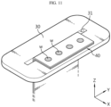
- FIG. 11 is a view showing a bus bar 30 and an electrode lead 40 welded by a welding device according to an embodiment of the present disclosure.
- the bus bar 30 may be physically and electrically coupled or connected to one or more electrode leads 40.
- the bus bar 30 may be in a configuration that is included in the battery module 50.
- the electrode lead 40 may be in a configuration that is included in the battery cell 53.
- the bus bar 30 and the electrode lead 40 may be coupled by welding.
- the electrode lead 40 may pass through the hole 31 of the bus bar 30 and then be bent to be coupled or connected to the bus bar 30.
- the bus bar 30 and the electrode lead 40 may be coupled or connected through a plurality of welding spots w, joints w, or welding portions w.
- the welding device may be configured to weld one or more electrode leads 40 to the bus bar 30.
- the plurality of materials welded by the welding device of the present disclosure may include a first material and a second material laminated on the first material and exposing a portion of the upper surface of the first material.
- the first material may be a bus bar 30, and the second material may be an electrode lead 40.
- the jig 800 may bring the second material 40 into close contact with the first material 30.
- the jig 800 may bring the electrode lead 40 into close contact with the bus bar 30.
- the electrode lead 40 may be bent to be in close contact with the bus bar 30.
- the processor 400 may be configured to control the movement of the jig 800.
- the processor 400 may form a welding portion w, a welding spot w, or a joint w that connects or couples the busbar 30 and the electrode lead 40.
- the boundary of the first material 30 and the second material 40 may refer to the perimeter or edge of the second material 40 that overlaps or is stacked on the first material 30.
- the boundary of the bus bar 30 and the electrode lead 40 may be the perimeter or edge of a portion of the electrode lead 40 that overlaps or is stacked on the bus bar 30.
- the processor 400 may scan the perimeter or edge of the portion of the electrode lead 40 that overlaps or is stacked on the bus bar 30.
- the processor 400 may scan, detect, sense, or recognize the welding work line before welding.
- the processor 400 may perform a more sophisticated welding operation by scanning the boundary of the bus bar 30 and the electrode lead 40.
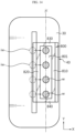
- FIG. 13 is a view showing a bus bar 30 and an electrode lead 40 scanned by a welding device according to an embodiment of the present disclosure.
- the jig 800 of the welding device may be configured to press the electrode lead 40 and may be configured such that a hole 801 is formed to penetrate in the vertical direction. Also, the hole 801 may be configured to expose at least a portion of the electrode lead.
- the processor 400 may scan around the jig 800 by controlling at least one of the scanner 500 and the galvo module 300 while turning on the scan laser 100 and turning off the welding laser 600.
- the scan trajectory st may be formed to vibrate in the X-axis direction and proceed in the -Y-axis direction around the longitudinal direction of the jig 800, a line of symmetry with respect to the longitudinal direction of the jig 800, or an axis parallel to the Y-axis.
- the processor 400 may sense, recognize, or search the perimeter and position of the jig 800 by measuring a distance between the focus of the scanner 500 and the scanner 500.
- the processor 400 may perform a more sophisticated welding operation by scanning, detecting, sensing, or recognizing the jig 800 before welding.
- the jig 800 of the welding device may be configured to include a first part 810 pressing the electrode lead 40 and a second part 820 facing the first part 810. Also, the jig 800 may further include a third part 830 connecting the first part 810 and the second part 820, and a fourth part 840 connecting the first part 810 and the second part 820 and facing the third part 830.
- the first part 810 to the fourth part 840 may be configured to form a hole 801.
- the first part 810 to the fourth part 840 may have a rectangular shape.
- the first part 810 to the fourth part 840 may be configured to press at least one of the electrode lead 40 and the bus bar 30.
- the jig 800 may prevent flying products generated by the welding operation from splashing or spreading while stably pressing the electrode lead 40.
- the processor 400 of the welding device may be configured to calibrate the preset welding work line based on coordinate information obtained by scanning the first part 810 and the second part 820.
- the processor 400 may be configured to calibrate the preset welding work line to the center line between the first part 810 and the second part 820.
- the processor 400 may be configured to calibrate the preset welding work line based on coordinate information obtained by scanning the third part 830 and the fourth part 840. In this case, the processor 400 may be configured to calibrate the preset welding work line based on the center line between the third part 830 and the fourth part 840.
- the processor 400 may calibrate or update the welding work line based on the first part 810 to the fourth part 840 of the jig 800. Since the first part 810 to the fourth part 840 form a rectangular shape, the center line between the first part 810 and the second part 820 or between the third part 830 and the fourth part 840 may improve the accuracy of calibration or update.
- FIG. 14 is a view showing an example in which a welding line is calibrated by a welding device according to an embodiment of the present disclosure.
- the processor 400 of the welding device may be configured to calibrate or update the previously established, stored, and set welding work line iw by scanning, detecting, sensing, or recognizing the jig 800.
- the processor 400 may calibrate or update the existing welding work line iw to the center line jc or line of symmetry jc of the jig 800.
- the processor 400 may calibrate or update the existing welding work line iw to the center line jc or line of symmetry jc between the first part 810 and the second part 820.
- the processor 400 may be configured to form a welding spot w, a joint w, or a welding portion w along the calibrated or updated welding work line jc.
- the processor 400 may improve welding quality and reduce welding defects by calibrating or updating the welding work line iw.
- FIG. 15 is a view showing a bus bar 30 and an electrode lead 40 scanned by a welding device according to another embodiment of the present disclosure.
- the jig 800 of the welding device may be configured to press the electrode lead 40 and may be configured such that a hole 801 is formed to penetrate in the vertical direction. Also, the hole 801 may be configured to expose at least a portion of the electrode lead 40 and at least a portion of the bus bar 30.
- the processor 400 may scan around the jig 800 by controlling at least one of the scanner 500 and the galvo module 300 while turning on the scan laser 100 and turning off the welding laser 600.
- the scan trajectory st may be formed to vibrate in the X-axis direction and proceed in the -Y-axis direction around the longitudinal direction of the jig 800, a line of symmetry with respect to the longitudinal direction of the jig 800, or an axis parallel to the Y-axis.
- the processor 400 may sense, recognize, or search the perimeter and position of the jig 800 by measuring a distance between the focus of the scanner 500 and the scanner 500.
- the processor 400 may sense, recognize, or search the boundary between the electrode lead 40 and the bus bar 30, or the edge or perimeter of the electrode lead 40 exposed through the jig 800.
- the processor 400 may perform a more sophisticated welding operation by scanning, detecting, sensing, or recognizing the jig 800 before welding.
- FIG. 16 is a view showing an example in which a welding line is calibrated by a welding device according to another embodiment of the present disclosure.
- the processor 400 of the welding device may be configured to calibrate or update the previously established, stored, and set welding work line iw by scanning, detecting, sensing, or recognizing the jig 800.
- the processor 400 may calibrate or update the existing welding work line iw to the center line jc or line of symmetry jc of the jig 800 with respect to the Y-axis direction.
- the processor 400 may calibrate or update the existing welding work line iw to the center line jc or line of symmetry jc between the first part 810 and the second part 820.
- the processor 400 may be configured to form a welding spot w, a joint w, or a welding portion w along the calibrated or updated welding work line jc. In this case, the processor 400 may perform calibration or update of the welding work line iw with respect to the X-axis direction.
- the processor 400 may improve welding quality and reduce welding defects by calibrating or updating the welding work line iw.
- FIG. 17 is a view showing a bus bar 30 and an electrode lead 40 scanned by a welding device according to still another embodiment of the present disclosure.
- the processor 400 of the welding device may scan around the jig 800 by controlling at least one of the scanner 500 and the galvo module 300 while turning on the scan laser 100 and turning off the welding laser 600.
- the scan trajectory st may be formed to vibrate in the Y-axis direction and proceed in the +X-axis direction around the longitudinal direction of the jig 800, a line of symmetry perpendicular to the longitudinal direction of the jig 800, or an axis parallel to the X-axis.
- the processor 400 may sense, recognize, or search the perimeter and position of the jig 800 by measuring a distance between the focus of the scanner 500 and the scanner 500. In addition, the processor 400 may sense, recognize, or search the boundary between the electrode lead 40 and the bus bar 30, or the edge or perimeter of the electrode lead 40 exposed through the jig 800.
- the processor 400 may perform a more sophisticated welding operation by scanning, detecting, sensing, or recognizing the jig 800 before welding.
- FIG. 18 is a view showing an example in which a welding line is calibrated by a welding device according to still another embodiment of the present disclosure.
- the processor 400 of the welding device according to an embodiment of the present disclosure may be configured to calibrate the preset welding work line iw based on coordinate information obtained by scanning the boundary of the bus bar 30 and the electrode lead 40.
- the processor 400 may calibrate or update the existing welding work line iw to the center line jc or line of symmetry jc of the jig 800 with respect to the X-axis direction.
- the processor 400 may calibrate or update the existing welding work line iw to the center line jc or line of symmetry jc between the third part 830 and the fourth part 840.
- the processor 400 may be configured to form a welding spot w, a joint w, or a welding portion w along the calibrated or updated welding work line jc. In this case, the processor 400 may perform calibration or update of the welding work line iw with respect to the Y-axis direction.
- the processor 400 may improve welding quality and reduce welding defects by calibrating or updating the welding work line iw.
- a battery cell according to one aspect of the present disclosure includes a welding spot, a welding joint, or a welding portion formed by the welding device according to the present disclosure.
- a battery module according to one aspect of the present disclosure includes a welding spot, a welding joint, or a welding portion formed by the welding device according to the present disclosure.
- a battery cell manufacturing device includes a welding device according to the present disclosure.
- a battery module manufacturing device includes a welding device according to the present disclosure.
- a welding method according to one aspect of the present disclosure uses a welding device according to the present disclosure.
Landscapes
- Physics & Mathematics (AREA)
- Optics & Photonics (AREA)
- Engineering & Computer Science (AREA)
- Mechanical Engineering (AREA)
- Plasma & Fusion (AREA)
- Chemical Kinetics & Catalysis (AREA)
- Chemical & Material Sciences (AREA)
- Electrochemistry (AREA)
- General Chemical & Material Sciences (AREA)
- Quality & Reliability (AREA)
- Connection Of Batteries Or Terminals (AREA)
- Laser Beam Processing (AREA)
- Battery Mounting, Suspending (AREA)
- Lining Or Joining Of Plastics Or The Like (AREA)
Abstract
Description
- The present disclosure relates to a welding device.
- The present application claims priority to
Korean Patent Application No. 10-2022-0084675 filed on July 8, 2022 Korean Patent Application No. 10-2023-0082154 filed on June 26, 2023 - Welding technology is widely used in various industrial fields. For example, in the battery field, welding technology is applied to welding between battery module cases or between leads and bus bars.
- Welding is the coupling of two or more members or parts, and it is necessary to secure a certain level or higher of welding quality so that the coupling state may be maintained reliably. However, according to the conventional welding method, welding quality is often not secured stably.
- In particular, the electrode leads of battery cells and bus bars may be coupled by laser welding. Also, the frame and end plate of a battery module or a battery module case may be coupled by laser welding. In this case, if the welding object is not placed precisely on the welding device or is misaligned, the welding work line may be deviated. Therefore, it is necessary to increase the accuracy of welding by appropriately calibrating or updating the welding work line before welding.
- The present disclosure is designed to solve the above-described problems and other problems.
- In particular, an object of the present disclosure may be to provide a welding device capable of increasing welding accuracy.
- Another object of the present disclosure may be to provide a welding device capable of inspecting welding quality in real time while welding is in progress.
- A welding device according to an embodiment of the present disclosure for achieving the above-described object is a welding device for welding a plurality of materials arranged to be in contact, and may include a scanner configured to deflect light; a welding laser configured to emit light toward the scanner; a galvo module configured to deflect light toward the scanner; a scan laser configured to emit light toward the galvo module; and a processor configured to control at least one of the scanner and the galvo module to scan boundaries of the plurality of materials.
- In addition, the processor may be configured to measure a distance between the focus at which the scanner is aimed and the scanner.
- In addition, the processor may calibrate the preset welding work line based on coordinate information obtained by scanning the boundaries of the plurality of materials.
- In addition, the processor may be configured to control the welding laser and the scanner to form a keyhole, and to control the scan laser and the galvo module to scan around the keyhole.
- In addition, at least one of the plurality of materials may be a frame of a battery module.
- In addition, the plurality of materials may include a first material; and a second material laminated on the first material and exposing a portion of the upper surface of the first material, wherein the welding device may further include a jig that brings the second material into close contact with the first material.
- In addition, the first material may be a bus bar, and the second material may be an electrode lead of a battery cell.
- In addition, the jig may be configured to press the electrode lead, and a hole may be formed to penetrate in a vertical direction, wherein the hole may be configured to expose at least a portion of the electrode lead and at least a portion of the bus bar.
- In addition, the processor may be configured to calibrate the preset welding work line based on coordinate information obtained by scanning the boundary of the bus bar and the electrode lead.
- In addition, the jig may include a first part pressing the electrode lead; and a second part facing the first part.
- In addition, the processor may calibrate the preset welding work line based on coordinate information obtained by scanning the first part and the second part.
- A battery cell according to the present disclosure is welded through the welding device of the present disclosure.
- In addition, a battery module according to the present disclosure is welded through the welding device of the present disclosure.
- In addition, a battery cell manufacturing device according to the present disclosure includes the welding device according to the present disclosure.
- In addition, a battery module manufacturing device according to the present disclosure includes the welding device according to the present disclosure.
- In addition, a welding method according to the present disclosure uses the welding device according to the present disclosure.
- According to at least one of the embodiments of the present disclosure, welding accuracy may be improved.
- According to at least one of the embodiments of the present disclosure, welding accuracy may be improved by appropriately calibrating or updating the welding work line even if the welding object is misaligned.
- According to at least one of the embodiments of the present disclosure, welding defects may be quickly and accurately sensed.
- The accompanying drawings illustrate a preferred embodiment of the present disclosure and together with the foregoing disclosure, serve to provide further understanding of the technical features of the present disclosure, and thus the present disclosure is not construed as being limited to the drawing.
-
FIG. 1 is a view showing a partial configuration of a welding device according to an embodiment of the present disclosure. -
FIG. 2 is a view schematically showing an optical configuration of a welding device according to an embodiment of the present disclosure. -
FIG. 3 is an exploded view showing a partial configuration of a battery module welded by a welding device according to an embodiment of the present disclosure. -
FIG. 4 is a perspective view showing the battery module ofFIG. 3 . -
FIG. 5 is an exploded view showing a partial configuration of another battery module welded by a welding device according to an embodiment of the present disclosure. -
FIG. 6 is a perspective view showing the battery module ofFIG. 5 . -
FIG. 7 is a view showing an example in which a battery module is scanned by a welding device according to an embodiment of the present disclosure. -
FIG. 8 is a view showing an example in which a welding line is calibrated by a welding device according to an embodiment of the present disclosure. -
FIG. 9 is a view showing an example in which a battery module is welded by a welding device according to an embodiment of the present disclosure. -
FIG. 10 is a view showing an example in which a welding portion is inspected by a welding device according to an embodiment of the present disclosure. -
FIG. 11 is a view showing a bus bar and an electrode lead welded by a welding device according to an embodiment of the present disclosure. -
FIG. 12 is a view showing a bus bar and an electrode lead aligned by a welding device according to an embodiment of the present disclosure. -
FIG. 13 is a view showing a bus bar and an electrode lead scanned by a welding device according to an embodiment of the present disclosure. -
FIG. 14 is a view showing an example in which a welding line is calibrated by a welding device according to an embodiment of the present disclosure. -
FIG. 15 is a view showing a bus bar and an electrode lead scanned by a welding device according to another embodiment of the present disclosure. -
FIG. 16 is a view showing an example in which a welding line is calibrated by a welding device according to another embodiment of the present disclosure. -
FIG. 17 is a view showing a bus bar and an electrode lead scanned by a welding device according to still another embodiment of the present disclosure. -
FIG. 18 is a view showing an example in which a welding line is calibrated by a welding device according to still another embodiment of the present disclosure. - Hereinafter, preferred embodiments of the present disclosure will be described in detail with reference to the accompanying drawings. Prior to the description, it should be understood that the terms used in the specification and the appended claims should not be construed as limited to general and dictionary meanings, but interpreted based on the meanings and concepts corresponding to technical aspects of the present disclosure on the basis of the principle that the inventor is allowed to define terms appropriately for the best explanation.
- Therefore, the description proposed herein is just a preferable example for the purpose of illustrations only, not intended to limit the scope of the disclosure, so it should be understood that other equivalents and modifications could be made thereto without departing from the scope of the disclosure.
-
FIG. 1 is a view showing a partial configuration of a welding device according to an embodiment of the present disclosure.FIG. 2 is a view schematically showing an optical configuration of a welding device according to an embodiment of the present disclosure. Referring toFIGS. 1 and2 , a welding device according to an embodiment of the present disclosure is a welding device for welding a plurality of materials 60 arranged to be in contact. Also, the welding device according to an embodiment of the present disclosure may include ascanner 500, awelding laser 600, agalvo module 300, ascan laser 100, and aprocessor 400. - The plurality of materials 60 may be disposed to be in contact for butt welding, edge welding, fringe welding, or overlap welding. The meaning of contact refers to the positional relationship of the plurality of materials 60 for welding, and the type of welding joint is not limited.
- The
scanner 500 may be configured to deflect light. Thescanner 500 may include ascan mirror 510 therein. Thescan mirror 510 may deflect light incident on thescanner 500. Also, thescan mirror 510 may be configured to be rotatable. Thescan mirror 510 may be configured to deflect light in various directions. - The
welding laser 600 mayoutput light 12. Thewelding laser 600 may emit light 12 toward thescanner 500. The light 12 emitted by thewelding laser 600 may have an intensity high enough to weld the plurality of materials 60. - The
galvo module 300 may be configured to deflect light. Thegalvo module 300 may include agalvo mirror 310 therein. Thegalvo mirror 310 may deflect light incident on thegalvo module 300. In addition, thegalvo mirror 310 may be configured to be rotatable. Thegalvo mirror 310 may be configured to deflect light in various directions. Also, thegalvo module 300 may be configured to deflect the incident light toward thescanner 500. In addition, thegalvo module 300 may be configured to be fastened, coupled, fixed, or assembled to one side of thescanner 500. - The
scan laser 100 mayoutput light 11. Thescan laser 100 may emit light 11 toward thegalvo module 300. The light 11 emitted by thescan laser 100 may have a weaker intensity than the light 12 emitted by thewelding laser 600. In addition, thescan laser 100 mayoutput light 11 having a wavelength different from that of thewelding laser 600. For example, thescan laser 100 may output visible light. Thescan laser 100 mayoutput light 11 for scanning the shape, location, surface, or boundary of the plurality of materials 60. In addition, thescan laser 100 may be configured to scan around the focus of the light 12 emitted by thewelding laser 600. - The
processor 400 may be configured to include afirst control computer 410 and asecond control computer 420. Thefirst control computer 410 may be physically, electrically, or optically connected to at least one of thescanner 500, thewelding laser 600, thescan laser 100, or thegalvo module 300. Thefirst control computer 410 may be configured to monitor or control at least one of thescanner 500, thewelding laser 600, thescan laser 100, or thegalvo module 300. Thesecond control computer 420 may be physically, electrically, or optically connected to thefirst control computer 410. Thesecond control computer 420 may be configured to monitor or control thefirst control computer 410. In addition, thesecond control computer 420 may include an interface unit capable of receiving commands from a user. Theprocessor 400 may be used to refer to thefirst control computer 410 and thesecond control computer 420. - The
processor 400 may be configured to scan the boundaries of the plurality of materials 60 by controlling at least one of thescanner 500 and thegalvo module 300. In this case, theprocessor 400 may turn off the output of thewelding laser 600 and turn on the output of thescan laser 100. Theprocessor 400 may scan the boundaries of the plurality of materials 60 before welding the plurality of materials 60. - According to this configuration of the present disclosure, the
processor 400 may scan, detect, sense, or recognize a welding work line before welding. Theprocessor 400 may perform a more sophisticated welding operation by scanning the boundaries of the plurality of materials 60. - Referring to
FIGS. 1 and2 , the welding device according to an embodiment of the present disclosure may be configured to further include anoptical module 200 or acondensing module 700. - The
scan laser 100 may be configured to emit light 11 toward theoptical module 200. Theoptical module 200 may output, deflect, or pass at least a portion of the incident light toward thegalvo module 300. Theoptical module 200 may be configured to include abeam splitter 210, areference mirror 220, and a detector (not shown). Thebeam splitter 210 may output, deflect, or pass at least a portion of the light incident on theoptical module 200 toward thegalvo mirror 310. In addition, thebeam splitter 210 may output, deflect, or pass at least a portion of the light incident on theoptical module 200 toward thereference mirror 220. Thereference mirror 220 may be configured to reflect the incident light toward the detector. Theprocessor 400 may be configured to acquire optical coherence tomography (OCT) through theoptical module 200. - The
condensing module 700 may be configured to be fastened, coupled, fixed, or assembled to one side of thescanner 500. Thecondensing module 700 may be configured to include afirst condensing lens 710 and asecond condensing lens 720. Thecondensing module 700 may be configured to focus light deflected by thescanner 500 toward a plurality of materials. The light 12 output from thewelding laser 600 and the light 11 output from thescan laser 100 may be focused on the plurality of materials 60 through thecondensing module 700. -
FIG. 3 is an exploded view showing a partial configuration of abattery module 50 welded by a welding device according to an embodiment of the present disclosure.FIG. 4 is a perspective view showing thebattery module 50 ofFIG. 3 . Referring toFIGS. 3 and4 , abattery module 50 welded by a welding device according to an embodiment of the present disclosure may be configured to include aframe 51, anend plate 52, and a plurality ofcells 53. - The
frame 51 may have a rectangular parallelepiped shape that is open in the vertical direction, in the front-rear direction, or in the Y-axis direction. Also, theframe 51 may provide space therein. Theframe 51 may be made of a metal material. - The
end plate 52 may be fastened, coupled, or fixed to theframe 51 on the front side and the rear side, respectively. Theend plate 52 and theframe 51 may be coupled through welding. A welding line wb or a welding portion wb may be formed along the perimeter of theend plate 52, the perimeter of the front side of theframe 51, or the perimeter of the rear side of theframe 51. - A plurality of
battery cells 53 may be accommodated in an inner space of theframe 51. The plurality ofbattery cells 53 may refer to secondary batteries. The plurality ofbattery cells 53 may be secondary batteries having a pouch shape. The plurality ofbattery cells 53 may be configured to be stacked inside theframe 51. - The welding device according to an embodiment of the present disclosure may be configured to form a welding line wb or a welding portion wb of the
battery module 50. -
FIG. 5 is an exploded view showing a partial configuration of anotherbattery module 50 welded by a welding device according to an embodiment of the present disclosure.FIG. 6 is a perspective view showing thebattery module 50 ofFIG. 5 . Referring toFIGS. 5 and6 , abattery module 50 welded by a welding device according to an embodiment of the present disclosure may be configured to include a U-frame 54, atop frame 55, and a plurality ofcells 53. - The U-frame 54 may have a U-shape. The U-frame 54 may be open in the vertical direction, in the front-rear direction, or in the Y-axis direction. In addition, the U-frame 54 may be open upward or in the +Z-axis direction. Also, the U-frame 54 may provide space therein. The U-frame 54 may be made of a metal material.
- The
top frame 55 may be fastened, coupled, or fixed to the U-frame 54. Thetop frame 55 and the U-frame 54 may be coupled through welding. Thetop frame 55 and the U-frame 54 may have space, respectively. Also, thetop frame 55 and the U-frame 54 may be fastened, coupled, or fixed to form a rectangular parallelepiped shape. A welding line wb or a welding portion wb may be formed along the edge of the U-frame 54 or along the edge of thetop frame 55. - A plurality of
battery cells 53 may be accommodated in an inner space formed by the U-frame 54 and thetop frame 55. The plurality ofbattery cells 53 may refer to secondary batteries. The plurality ofbattery cells 53 may be secondary batteries having a pouch shape. The plurality ofbattery cells 53 may be configured to be stacked in the inner space formed by the U-frame 54 and thetop frame 55. - The welding device according to an embodiment of the present disclosure may be configured to form a welding line wb or a welding portion wb of the
battery module 50. -
FIG. 7 is a view showing an example in which a battery module is scanned by a welding device according to an embodiment of the present disclosure. Referring toFIGS. 1 and7 , theprocessor 400 of the welding device according to an embodiment of the present disclosure may be configured to measure a distance between the focus wf at which thescanner 500 is aimed and thescanner 500. The welding device may be configured to weld thefirst material 10 and thesecond material 20. Thefirst material 10 and thesecond material 20 may be made of a metal material. Also, thefirst material 10 and thesecond material 20 may be in contact for welding. For example, thefirst material 10 and thesecond material 20 may be theframe 51,U-frame 54,top frame 55, orend plate 52 of thebattery module 50. - The
processor 400 may scan thefirst material 10 and thesecond material 20 by controlling at least one of thescanner 500 and thegalvo module 300 while turning on thescan laser 100 and turning off thewelding laser 600. In this case, the scan trajectory st may be formed to vibrate in the Y-axis direction around the boundary of thefirst material 10 and thesecond material 20 and proceed in the +X-axis direction. Theprocessor 400 may sense, recognize, or search the boundary of thefirst material 10 and thesecond material 20 by measuring a distance between the focus wf of thescanner 500 and thescanner 500. Alternatively, theprocessor 400 may sense, recognize, or search a gap formed between thefirst material 10 and thesecond material 20. - According to this configuration of the present disclosure, the
processor 400 may scan, detect, sense, or recognize the welding work line before welding. Theprocessor 400 may perform a more sophisticated welding operation by scanning the boundaries or gaps of the plurality ofmaterials -
FIG. 8 is a view showing an example in which a welding line is calibrated by a welding device according to an embodiment of the present disclosure. Referring toFIGS. 1 and8 , theprocessor 400 of the welding device according to an embodiment of the present disclosure may be configured to calibrate the preset welding work line iwb based on coordinate information obtained by scanning the boundaries of the plurality ofmaterials - The
processor 400 may be configured to include the previously established, stored, and set welding work line iwb information. In this case, the welding work line iwb information may be coordinate information on the X-Y plane. In addition, theprocessor 400 may be configured to calibrate or update the previously established, stored, and set welding work line iwb based on coordinate information obtained by scanning the boundaries of the plurality ofmaterials processor 400 may calibrate or update the existing welding work line iwb to the center line gc of the gap or boundary between thefirst material 10 and thesecond material 20. Also, theprocessor 400 may be configured to perform a welding operation along the calibrated or updated welding work line gc. - According to this configuration of the present disclosure, the
processor 400 may improve welding quality and reduce welding defects by calibrating or updating the welding work line iwb. -
FIG. 9 is a view showing an example in which a battery module is welded by a welding device according to an embodiment of the present disclosure. Referring toFIGS. 1 and9 , theprocessor 400 of the welding device according to an embodiment of the present disclosure may be configured to control thewelding laser 600 and thescanner 500 to form a keyhole k, and to control thescan laser 100 and thegalvo module 300 to scan around the keyhole k. - The
processor 400 may turn on thewelding laser 600 and control thescanner 500 to weld thefirst material 10 and thesecond material 20. In this case, theprocessor 400 may control thewelding laser 600 and thescanner 500 so that welding proceeds along the calibrated or updated welding work line gc. Theprocessor 400 may form a welding spot, joint, a welding portion, or a keyhole k in the gap or boundary between thefirst material 10 and thesecond material 20. - According to this configuration of the present disclosure, the
processor 400 may perform welding by calibrating or updating the welding work line iwb, thereby improving welding quality and reducing welding defects. -
FIG. 10 is a view showing an example in which a welding portion is inspected by a welding device according to an embodiment of the present disclosure. Referring toFIGS. 1 and10 , theprocessor 400 of the welding device according to an embodiment of the present disclosure may be configured to perform welding quality inspection while simultaneously performing welding. - While welding is in progress, the
processor 400 may turn on thescan laser 100 and vibrate in the Y-axis direction around the welding spot, joint, welding portion, or keyhole k to proceed with the scan. In this case, theprocessor 400 may control thegalvo module 300 to deflect the light 11 emitted from thescan laser 100. Theprocessor 400 may be configured to control at least one of thescan laser 100 and thegalvo module 300 to sense or measure the penetration depth of the welding spot, joint, welding portion, or keyhole k. The welding quality inspection may proceed along the direction of welding progress. - According to this configuration of the present disclosure, the
processor 400 may quickly sense welding defects by performing welding quality inspection while simultaneously performing welding. As a result, welding defects may be quickly corrected or the settings of the welding device may be quickly corrected. -
FIG. 11 is a view showing abus bar 30 and anelectrode lead 40 welded by a welding device according to an embodiment of the present disclosure. Referring toFIG. 11 , thebus bar 30 may be physically and electrically coupled or connected to one or more electrode leads 40. Thebus bar 30 may be in a configuration that is included in thebattery module 50. Also, theelectrode lead 40 may be in a configuration that is included in thebattery cell 53. Thebus bar 30 and theelectrode lead 40 may be coupled by welding. Theelectrode lead 40 may pass through thehole 31 of thebus bar 30 and then be bent to be coupled or connected to thebus bar 30. Thebus bar 30 and theelectrode lead 40 may be coupled or connected through a plurality of welding spots w, joints w, or welding portions w. - According to this configuration of the present disclosure, the welding device according to an embodiment of the present disclosure may be configured to weld one or more electrode leads 40 to the
bus bar 30. -
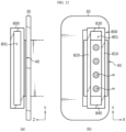
FIG. 12 is a view showing abus bar 30 and anelectrode lead 40 aligned by a welding device according to an embodiment of the present disclosure.FIG. 12 (a) is a view showing that thejig 800 brings theelectrode lead 40 into close contact with thebus bar 30.FIG. 12 (b) is a view showing thejig 800 that brings theelectrode lead 40 into close contact with thebus bar 30 when viewed from above. Referring toFIGS. 1 and12 , the welding device according to an embodiment of the present disclosure may be configured to further include ajig 800. Thejig 800 may refer to a maskingjig 800. In this case, the plurality of materials welded by the welding device of the present disclosure may include a first material and a second material laminated on the first material and exposing a portion of the upper surface of the first material. For example, the first material may be abus bar 30, and the second material may be anelectrode lead 40. Also, thejig 800 may bring thesecond material 40 into close contact with thefirst material 30. For example, thejig 800 may bring theelectrode lead 40 into close contact with thebus bar 30. In this case, theelectrode lead 40 may be bent to be in close contact with thebus bar 30. Theprocessor 400 may be configured to control the movement of thejig 800. Also, theprocessor 400 may form a welding portion w, a welding spot w, or a joint w that connects or couples thebusbar 30 and theelectrode lead 40. - In this case, the boundary of the
first material 30 and thesecond material 40 may refer to the perimeter or edge of thesecond material 40 that overlaps or is stacked on thefirst material 30. For example, the boundary of thebus bar 30 and theelectrode lead 40 may be the perimeter or edge of a portion of theelectrode lead 40 that overlaps or is stacked on thebus bar 30. Theprocessor 400 may scan the perimeter or edge of the portion of theelectrode lead 40 that overlaps or is stacked on thebus bar 30. - According to this configuration of the present disclosure, the
processor 400 may scan, detect, sense, or recognize the welding work line before welding. Theprocessor 400 may perform a more sophisticated welding operation by scanning the boundary of thebus bar 30 and theelectrode lead 40. -
FIG. 13 is a view showing abus bar 30 and anelectrode lead 40 scanned by a welding device according to an embodiment of the present disclosure. Referring toFIGS. 1 ,12 , and13 , thejig 800 of the welding device according to an embodiment of the present disclosure may be configured to press theelectrode lead 40 and may be configured such that ahole 801 is formed to penetrate in the vertical direction. Also, thehole 801 may be configured to expose at least a portion of the electrode lead. - The
processor 400 may scan around thejig 800 by controlling at least one of thescanner 500 and thegalvo module 300 while turning on thescan laser 100 and turning off thewelding laser 600. In this case, the scan trajectory st may be formed to vibrate in the X-axis direction and proceed in the -Y-axis direction around the longitudinal direction of thejig 800, a line of symmetry with respect to the longitudinal direction of thejig 800, or an axis parallel to the Y-axis. Theprocessor 400 may sense, recognize, or search the perimeter and position of thejig 800 by measuring a distance between the focus of thescanner 500 and thescanner 500. - According to this configuration of the present disclosure, the
processor 400 may perform a more sophisticated welding operation by scanning, detecting, sensing, or recognizing thejig 800 before welding. - Referring to
FIGS. 1 and13 , thejig 800 of the welding device according to an embodiment of the present disclosure may be configured to include afirst part 810 pressing theelectrode lead 40 and asecond part 820 facing thefirst part 810. Also, thejig 800 may further include athird part 830 connecting thefirst part 810 and thesecond part 820, and afourth part 840 connecting thefirst part 810 and thesecond part 820 and facing thethird part 830. Thefirst part 810 to thefourth part 840 may be configured to form ahole 801. In addition, thefirst part 810 to thefourth part 840 may have a rectangular shape. Also, thefirst part 810 to thefourth part 840 may be configured to press at least one of theelectrode lead 40 and thebus bar 30. - According to this configuration of the present disclosure, the
jig 800 may prevent flying products generated by the welding operation from splashing or spreading while stably pressing theelectrode lead 40. - Referring to
FIGS. 1 and13 , theprocessor 400 of the welding device according to an embodiment of the present disclosure may be configured to calibrate the preset welding work line based on coordinate information obtained by scanning thefirst part 810 and thesecond part 820. In this case, theprocessor 400 may be configured to calibrate the preset welding work line to the center line between thefirst part 810 and thesecond part 820. - In addition, the
processor 400 may be configured to calibrate the preset welding work line based on coordinate information obtained by scanning thethird part 830 and thefourth part 840. In this case, theprocessor 400 may be configured to calibrate the preset welding work line based on the center line between thethird part 830 and thefourth part 840. - According to this configuration of the present disclosure, the
processor 400 may calibrate or update the welding work line based on thefirst part 810 to thefourth part 840 of thejig 800. Since thefirst part 810 to thefourth part 840 form a rectangular shape, the center line between thefirst part 810 and thesecond part 820 or between thethird part 830 and thefourth part 840 may improve the accuracy of calibration or update. -
FIG. 14 is a view showing an example in which a welding line is calibrated by a welding device according to an embodiment of the present disclosure. Referring toFIGS. 1 and14 , theprocessor 400 of the welding device according to an embodiment of the present disclosure may be configured to calibrate or update the previously established, stored, and set welding work line iw by scanning, detecting, sensing, or recognizing thejig 800. For example, theprocessor 400 may calibrate or update the existing welding work line iw to the center line jc or line of symmetry jc of thejig 800. Alternatively, theprocessor 400 may calibrate or update the existing welding work line iw to the center line jc or line of symmetry jc between thefirst part 810 and thesecond part 820. Also, theprocessor 400 may be configured to form a welding spot w, a joint w, or a welding portion w along the calibrated or updated welding work line jc. - According to this configuration of the present disclosure, the
processor 400 may improve welding quality and reduce welding defects by calibrating or updating the welding work line iw. -
FIG. 15 is a view showing abus bar 30 and anelectrode lead 40 scanned by a welding device according to another embodiment of the present disclosure. Referring toFIGS. 1 and15 , thejig 800 of the welding device according to an embodiment of the present disclosure may be configured to press theelectrode lead 40 and may be configured such that ahole 801 is formed to penetrate in the vertical direction. Also, thehole 801 may be configured to expose at least a portion of theelectrode lead 40 and at least a portion of thebus bar 30. - The
processor 400 may scan around thejig 800 by controlling at least one of thescanner 500 and thegalvo module 300 while turning on thescan laser 100 and turning off thewelding laser 600. In this case, the scan trajectory st may be formed to vibrate in the X-axis direction and proceed in the -Y-axis direction around the longitudinal direction of thejig 800, a line of symmetry with respect to the longitudinal direction of thejig 800, or an axis parallel to the Y-axis. Theprocessor 400 may sense, recognize, or search the perimeter and position of thejig 800 by measuring a distance between the focus of thescanner 500 and thescanner 500. In addition, theprocessor 400 may sense, recognize, or search the boundary between theelectrode lead 40 and thebus bar 30, or the edge or perimeter of theelectrode lead 40 exposed through thejig 800. - According to this configuration of the present disclosure, the
processor 400 may perform a more sophisticated welding operation by scanning, detecting, sensing, or recognizing thejig 800 before welding. -
FIG. 16 is a view showing an example in which a welding line is calibrated by a welding device according to another embodiment of the present disclosure. Referring toFIGS. 1 and16 , theprocessor 400 of the welding device may be configured to calibrate or update the previously established, stored, and set welding work line iw by scanning, detecting, sensing, or recognizing thejig 800. For example, theprocessor 400 may calibrate or update the existing welding work line iw to the center line jc or line of symmetry jc of thejig 800 with respect to the Y-axis direction. Alternatively, theprocessor 400 may calibrate or update the existing welding work line iw to the center line jc or line of symmetry jc between thefirst part 810 and thesecond part 820. Also, theprocessor 400 may be configured to form a welding spot w, a joint w, or a welding portion w along the calibrated or updated welding work line jc. In this case, theprocessor 400 may perform calibration or update of the welding work line iw with respect to the X-axis direction. - According to this configuration of the present disclosure, the
processor 400 may improve welding quality and reduce welding defects by calibrating or updating the welding work line iw. -
FIG. 17 is a view showing abus bar 30 and anelectrode lead 40 scanned by a welding device according to still another embodiment of the present disclosure. Referring toFIGS. 1 and17 , theprocessor 400 of the welding device according to still another embodiment of the present disclosure may scan around thejig 800 by controlling at least one of thescanner 500 and thegalvo module 300 while turning on thescan laser 100 and turning off thewelding laser 600. In this case, the scan trajectory st may be formed to vibrate in the Y-axis direction and proceed in the +X-axis direction around the longitudinal direction of thejig 800, a line of symmetry perpendicular to the longitudinal direction of thejig 800, or an axis parallel to the X-axis. Theprocessor 400 may sense, recognize, or search the perimeter and position of thejig 800 by measuring a distance between the focus of thescanner 500 and thescanner 500. In addition, theprocessor 400 may sense, recognize, or search the boundary between theelectrode lead 40 and thebus bar 30, or the edge or perimeter of theelectrode lead 40 exposed through thejig 800. - According to this configuration of the present disclosure, the
processor 400 may perform a more sophisticated welding operation by scanning, detecting, sensing, or recognizing thejig 800 before welding. -
FIG. 18 is a view showing an example in which a welding line is calibrated by a welding device according to still another embodiment of the present disclosure. Theprocessor 400 of the welding device according to an embodiment of the present disclosure may be configured to calibrate the preset welding work line iw based on coordinate information obtained by scanning the boundary of thebus bar 30 and theelectrode lead 40. For example, theprocessor 400 may calibrate or update the existing welding work line iw to the center line jc or line of symmetry jc of thejig 800 with respect to the X-axis direction. Alternatively, theprocessor 400 may calibrate or update the existing welding work line iw to the center line jc or line of symmetry jc between thethird part 830 and thefourth part 840. Also, theprocessor 400 may be configured to form a welding spot w, a joint w, or a welding portion w along the calibrated or updated welding work line jc. In this case, theprocessor 400 may perform calibration or update of the welding work line iw with respect to the Y-axis direction. - According to this configuration of the present disclosure, the
processor 400 may improve welding quality and reduce welding defects by calibrating or updating the welding work line iw. - A battery cell according to one aspect of the present disclosure includes a welding spot, a welding joint, or a welding portion formed by the welding device according to the present disclosure.
- In addition, a battery module according to one aspect of the present disclosure includes a welding spot, a welding joint, or a welding portion formed by the welding device according to the present disclosure.
- In addition, a battery cell manufacturing device according to one aspect of the present disclosure includes a welding device according to the present disclosure.
- In addition, a battery module manufacturing device according to one aspect of the present disclosure includes a welding device according to the present disclosure.
- In addition, a welding method according to one aspect of the present disclosure uses a welding device according to the present disclosure.
- Meanwhile, the terms indicating directions as used herein such as upper, lower, left, right, front, and rear are used for convenience of description only, and it is obvious to those skilled in the art that the term may change depending on the position of the stated element or an observer.
- While the present disclosure has been hereinabove described with regard to a limited number of embodiments and drawings, the present disclosure is not limited thereto and it is obvious to those skilled in the art that a variety of modifications and changes may be made thereto within the technical aspects of the present disclosure and the equivalent scope of the appended claims.
Claims (16)
- A welding device for welding a plurality of materials arranged to be in contact, comprising:a scanner configured to deflect light;a welding laser configured to emit light toward the scanner;a galvo module configured to deflect light toward the scanner;a scan laser configured to emit light toward the galvo module; anda processor configured to control at least one of the scanner and the galvo module to scan boundaries of the plurality of materials.
- The welding device according to claim 1,
wherein the processor is configured to measure a distance between the focus at which the scanner is aimed and the scanner. - The welding device according to claim 1,
wherein the processor calibrates the preset welding work line based on coordinate information obtained by scanning the boundaries of the plurality of materials. - The welding device according to claim 1,
wherein the processor is configured to control the welding laser and the scanner to form a keyhole, and to control the scan laser and the galvo module to scan around the keyhole. - The welding device according to claim 1,
wherein at least one of the plurality of materials is a frame of a battery module. - The welding device according to claim 1,
wherein the plurality of materials comprise:a first material; anda second material laminated on the first material and exposing a portion of the upper surface of the first material,wherein the welding device further comprises a jig that brings the second material into close contact with the first material. - The welding device according to claim 6,wherein the first material is a bus bar, andthe second material is an electrode lead of a battery cell.
- The welding device according to claim 7,wherein the jig is configured to press the electrode lead, and a hole is formed to penetrate in a vertical direction,wherein the hole is configured to expose at least a portion of the electrode lead and at least a portion of the bus bar.
- The welding device according to claim 8,
wherein the processor calibrates the preset welding work line based on coordinate information obtained by scanning the boundary of the bus bar and the electrode lead. - The welding device according to claim 7,
wherein the jig comprises:a first part pressing the electrode lead; anda second part facing the first part. - The welding device according to claim 10,
wherein the processor calibrates the preset welding work line based on coordinate information obtained by scanning the first part and the second part. - A battery cell welded through the welding device according to any one of claims 1 to 11.
- A battery module welded through the welding device according to any one of claims 1 to 11.
- A battery cell manufacturing device comprising the welding device according to any one of claims 1 to 4 and 6 to 11.
- A battery module manufacturing device comprising the welding device according to any one of claims 1 to 11.
- A welding method using the welding device according to any one of claims 1 to 11.
Applications Claiming Priority (3)
| Application Number | Priority Date | Filing Date | Title |
|---|---|---|---|
| KR20220084675 | 2022-07-08 | ||
| KR1020230082154A KR102951939B1 (en) | 2022-07-08 | 2023-06-26 | Welding machine |
| PCT/KR2023/009710 WO2024010429A1 (en) | 2022-07-08 | 2023-07-07 | Welding machine |
Publications (2)
| Publication Number | Publication Date |
|---|---|
| EP4378620A1 true EP4378620A1 (en) | 2024-06-05 |
| EP4378620A4 EP4378620A4 (en) | 2025-04-09 |
Family
ID=89453776
Family Applications (1)
| Application Number | Title | Priority Date | Filing Date |
|---|---|---|---|
| EP23835895.6A Pending EP4378620A4 (en) | 2022-07-08 | 2023-07-07 | WELDING MACHINE |
Country Status (4)
| Country | Link |
|---|---|
| US (1) | US20250033144A1 (en) |
| EP (1) | EP4378620A4 (en) |
| JP (1) | JP7739610B2 (en) |
| WO (1) | WO2024010429A1 (en) |
Cited By (1)
| Publication number | Priority date | Publication date | Assignee | Title |
|---|---|---|---|---|
| EP4679609A1 (en) * | 2024-07-10 | 2026-01-14 | Hyundai Mobis Co., Ltd. | Cell lead support module |
Families Citing this family (2)
| Publication number | Priority date | Publication date | Assignee | Title |
|---|---|---|---|---|
| US20240097283A1 (en) * | 2022-09-15 | 2024-03-21 | Ats Corporation | Systems and methods for manufacturing a battery module |
| CN117020457B (en) * | 2023-10-08 | 2024-02-06 | 宁德时代新能源科技股份有限公司 | Welding system and spot inspection method of welding system |
Family Cites Families (15)
| Publication number | Priority date | Publication date | Assignee | Title |
|---|---|---|---|---|
| KR101348794B1 (en) * | 2012-04-02 | 2014-01-08 | 주식회사 프로맥스 | Welding robot for cylinder circumference using of laser scanning |
| KR102241333B1 (en) * | 2014-04-24 | 2021-04-16 | 에스케이이노베이션 주식회사 | Battery module for secondary battery |
| JP2018153842A (en) * | 2017-03-17 | 2018-10-04 | トヨタ自動車株式会社 | Measuring device and laser welding device |
| JP7006915B2 (en) * | 2017-09-27 | 2022-02-10 | 株式会社タマリ工業 | Welding appearance defect detection device, laser welding device, and welding appearance defect detection method |
| DE102017010055A1 (en) | 2017-10-27 | 2019-05-02 | Lessmüller Lasertechnik GmbH | Laser beam welding of geometric figures with OCT seam guide |
| DE102017126867A1 (en) | 2017-11-15 | 2019-05-16 | Precitec Gmbh & Co. Kg | Laser processing system and method for laser processing |
| EP3778101B1 (en) * | 2018-04-13 | 2024-01-17 | Panasonic Intellectual Property Management Co., Ltd. | Laser welding device |
| DE102018219129B3 (en) * | 2018-11-09 | 2019-11-07 | Trumpf Laser Gmbh | Method and computer program product for OCT measurement beam adjustment |
| KR102224371B1 (en) * | 2019-02-11 | 2021-03-08 | 주식회사 휴비스 | Monitoring system for inspection of Laser welding portion |
| KR102506245B1 (en) * | 2019-11-14 | 2023-03-03 | 주식회사 엘지에너지솔루션 | Battery module, method of manufacturing battery module and battery pack including battery module |
| DE102020203983A1 (en) | 2020-03-27 | 2021-09-30 | Trumpf Laser Gmbh | Method for OCT weld seam monitoring as well as the associated laser processing machine and computer program product |
| KR102800478B1 (en) * | 2020-08-05 | 2025-04-23 | 주식회사 엘지에너지솔루션 | Battery module, battery pack including the same and method of manufacturing battery module |
| DE102020210778A1 (en) * | 2020-08-26 | 2022-03-03 | Trumpf Laser Gmbh | Method for monitoring and/or controlling a laser welding process using an OCT-detected melting or welding bead geometry and associated processing machine and computer program product |
| KR102543403B1 (en) | 2020-12-14 | 2023-06-14 | (주)아이벡스메디칼시스템즈 | Automatic pressure control method of hyperbaric oxygen chamber |
| KR102694920B1 (en) | 2021-12-01 | 2024-08-14 | 주식회사 오션소프트 | Method for determining the installation location of traffic information detector for interrupted traffic flow, and method for initial queue processing at a signal intersection and method for measuring congestion information using the traffic information detector for interrupted traffic flow |
-
2023
- 2023-07-07 US US18/716,412 patent/US20250033144A1/en active Pending
- 2023-07-07 WO PCT/KR2023/009710 patent/WO2024010429A1/en not_active Ceased
- 2023-07-07 JP JP2024523235A patent/JP7739610B2/en active Active
- 2023-07-07 EP EP23835895.6A patent/EP4378620A4/en active Pending
Cited By (1)
| Publication number | Priority date | Publication date | Assignee | Title |
|---|---|---|---|---|
| EP4679609A1 (en) * | 2024-07-10 | 2026-01-14 | Hyundai Mobis Co., Ltd. | Cell lead support module |
Also Published As
| Publication number | Publication date |
|---|---|
| WO2024010429A1 (en) | 2024-01-11 |
| JP7739610B2 (en) | 2025-09-16 |
| US20250033144A1 (en) | 2025-01-30 |
| JP2024538191A (en) | 2024-10-18 |
| EP4378620A4 (en) | 2025-04-09 |
Similar Documents
| Publication | Publication Date | Title |
|---|---|---|
| US20250033144A1 (en) | Welding device | |
| KR102951939B1 (en) | Welding machine | |
| US11951564B2 (en) | Method and computer program product for OCT measurement beam adjustment | |
| US10166630B2 (en) | Optical measuring device for monitoring a joint seam, joining head and laser welding head with same | |
| US20210187657A1 (en) | Method and device for monitoring a joining seam during joining by means of a laser beam | |
| US12313463B2 (en) | Method for calibrating one or more optical sensors of a laser machining head, laser machining head, and laser machining system | |
| CN111055030A (en) | A beam pointing stability monitoring and feedback device and method | |
| KR20180123521A (en) | Axis calibration of beam machining machine | |
| JP6415281B2 (en) | Probe apparatus and probe method | |
| CN113369681B (en) | A detection device for laser welding focal length | |
| US10807196B2 (en) | Method for manufacturing laser processed product | |
| CN100544576C (en) | Solder joint determination method, solder inspection method, and solder inspection device | |
| CN117754168B (en) | Laser welding penetration detection system, correction method, detection method and storage medium | |
| JP2009115767A (en) | Welding quality inspection device and welding quality inspection method | |
| US20250198741A1 (en) | Method for calibrating a measurement scanner on a laser-working optical unit | |
| CN223084038U (en) | Penetration detection system and laser welding system | |
| CN117916053A (en) | Welding equipment | |
| CN215145675U (en) | A detection device for laser welding focal length | |
| JP2000098271A (en) | Galvano-mirror drive device | |
| JP7193566B2 (en) | Metal separator inspection method and metal separator inspection apparatus | |
| CN117697197A (en) | Laser welding penetration detection chromatic aberration compensation method, detection method and storage medium | |
| US7601949B2 (en) | Optical scanner device | |
| JPH11285880A (en) | Verification device for proofreading calibration of welding machine and proofreading method | |
| CN116367956A (en) | Calibration equipment, processing systems and calibration methods | |
| JP3886356B2 (en) | Attaching the optical fiber to the light emitting / receiving module |
Legal Events
| Date | Code | Title | Description |
|---|---|---|---|
| STAA | Information on the status of an ep patent application or granted ep patent |
Free format text: STATUS: THE INTERNATIONAL PUBLICATION HAS BEEN MADE |
|
| PUAI | Public reference made under article 153(3) epc to a published international application that has entered the european phase |
Free format text: ORIGINAL CODE: 0009012 |
|
| STAA | Information on the status of an ep patent application or granted ep patent |
Free format text: STATUS: REQUEST FOR EXAMINATION WAS MADE |
|
| 17P | Request for examination filed |
Effective date: 20240227 |
|
| AK | Designated contracting states |
Kind code of ref document: A1 Designated state(s): AL AT BE BG CH CY CZ DE DK EE ES FI FR GB GR HR HU IE IS IT LI LT LU LV MC ME MK MT NL NO PL PT RO RS SE SI SK SM TR |
|
| REG | Reference to a national code |
Ref country code: DE Ref legal event code: R079 Free format text: PREVIOUS MAIN CLASS: B23K0031000000 Ipc: B23K0031120000 |
|
| A4 | Supplementary search report drawn up and despatched |
Effective date: 20250311 |
|
| RIC1 | Information provided on ipc code assigned before grant |
Ipc: B23K 101/38 20060101ALN20250306BHEP Ipc: H01M 50/516 20210101ALI20250306BHEP Ipc: H01M 50/209 20210101ALI20250306BHEP Ipc: B23K 26/26 20140101ALI20250306BHEP Ipc: B23K 26/082 20140101ALI20250306BHEP Ipc: B23K 26/044 20140101ALI20250306BHEP Ipc: B23K 31/12 20060101AFI20250306BHEP |
|
| STAA | Information on the status of an ep patent application or granted ep patent |
Free format text: STATUS: EXAMINATION IS IN PROGRESS |
|
| 17Q | First examination report despatched |
Effective date: 20250811 |
|
| DAV | Request for validation of the european patent (deleted) | ||
| DAX | Request for extension of the european patent (deleted) | ||
| GRAP | Despatch of communication of intention to grant a patent |
Free format text: ORIGINAL CODE: EPIDOSNIGR1 |
|
| STAA | Information on the status of an ep patent application or granted ep patent |
Free format text: STATUS: GRANT OF PATENT IS INTENDED |
|
| RIC1 | Information provided on ipc code assigned before grant |
Ipc: B23K 31/12 20060101AFI20260402BHEP Ipc: B23K 26/044 20140101ALI20260402BHEP Ipc: B23K 26/082 20140101ALI20260402BHEP Ipc: B23K 26/26 20140101ALI20260402BHEP Ipc: H01M 50/209 20210101ALI20260402BHEP Ipc: H01M 50/516 20210101ALI20260402BHEP Ipc: B23K 101/38 20060101ALN20260402BHEP |