EP4378565A1 - Denitration device - Google Patents
Denitration device Download PDFInfo
- Publication number
- EP4378565A1 EP4378565A1 EP21959266.4A EP21959266A EP4378565A1 EP 4378565 A1 EP4378565 A1 EP 4378565A1 EP 21959266 A EP21959266 A EP 21959266A EP 4378565 A1 EP4378565 A1 EP 4378565A1
- Authority
- EP
- European Patent Office
- Prior art keywords
- exhaust gas
- channel
- denitration
- cement kiln
- duct
- Prior art date
- Legal status (The legal status is an assumption and is not a legal conclusion. Google has not performed a legal analysis and makes no representation as to the accuracy of the status listed.)
- Granted
Links
Images



Classifications
-
- B—PERFORMING OPERATIONS; TRANSPORTING
- B01—PHYSICAL OR CHEMICAL PROCESSES OR APPARATUS IN GENERAL
- B01D—SEPARATION
- B01D53/00—Separation of gases or vapours; Recovering vapours of volatile solvents from gases; Chemical or biological purification of waste gases, e.g. engine exhaust gases, smoke, fumes, flue gases, aerosols
- B01D53/34—Chemical or biological purification of waste gases
- B01D53/74—General processes for purification of waste gases; Apparatus or devices specially adapted therefor
- B01D53/86—Catalytic processes
- B01D53/8621—Removing nitrogen compounds
- B01D53/8625—Nitrogen oxides
- B01D53/8631—Processes characterised by a specific device
-
- C—CHEMISTRY; METALLURGY
- C04—CEMENTS; CONCRETE; ARTIFICIAL STONE; CERAMICS; REFRACTORIES
- C04B—LIME, MAGNESIA; SLAG; CEMENTS; COMPOSITIONS THEREOF, e.g. MORTARS, CONCRETE OR LIKE BUILDING MATERIALS; ARTIFICIAL STONE; CERAMICS; REFRACTORIES; TREATMENT OF NATURAL STONE
- C04B7/00—Hydraulic cements
- C04B7/36—Manufacture of hydraulic cements in general
- C04B7/364—Avoiding environmental pollution during cement-manufacturing
-
- B—PERFORMING OPERATIONS; TRANSPORTING
- B01—PHYSICAL OR CHEMICAL PROCESSES OR APPARATUS IN GENERAL
- B01D—SEPARATION
- B01D2251/00—Reactants
- B01D2251/20—Reductants
- B01D2251/206—Ammonium compounds
- B01D2251/2062—Ammonia
-
- B—PERFORMING OPERATIONS; TRANSPORTING
- B01—PHYSICAL OR CHEMICAL PROCESSES OR APPARATUS IN GENERAL
- B01D—SEPARATION
- B01D2251/00—Reactants
- B01D2251/20—Reductants
- B01D2251/206—Ammonium compounds
- B01D2251/2067—Urea
-
- B—PERFORMING OPERATIONS; TRANSPORTING
- B01—PHYSICAL OR CHEMICAL PROCESSES OR APPARATUS IN GENERAL
- B01D—SEPARATION
- B01D2255/00—Catalysts
- B01D2255/20—Metals or compounds thereof
- B01D2255/207—Transition metals
- B01D2255/20707—Titanium
-
- B—PERFORMING OPERATIONS; TRANSPORTING
- B01—PHYSICAL OR CHEMICAL PROCESSES OR APPARATUS IN GENERAL
- B01D—SEPARATION
- B01D2255/00—Catalysts
- B01D2255/20—Metals or compounds thereof
- B01D2255/207—Transition metals
- B01D2255/20723—Vanadium
-
- B—PERFORMING OPERATIONS; TRANSPORTING
- B01—PHYSICAL OR CHEMICAL PROCESSES OR APPARATUS IN GENERAL
- B01D—SEPARATION
- B01D2255/00—Catalysts
- B01D2255/20—Metals or compounds thereof
- B01D2255/207—Transition metals
- B01D2255/2073—Manganese
-
- B—PERFORMING OPERATIONS; TRANSPORTING
- B01—PHYSICAL OR CHEMICAL PROCESSES OR APPARATUS IN GENERAL
- B01D—SEPARATION
- B01D2255/00—Catalysts
- B01D2255/20—Metals or compounds thereof
- B01D2255/207—Transition metals
- B01D2255/20738—Iron
-
- B—PERFORMING OPERATIONS; TRANSPORTING
- B01—PHYSICAL OR CHEMICAL PROCESSES OR APPARATUS IN GENERAL
- B01D—SEPARATION
- B01D2255/00—Catalysts
- B01D2255/20—Metals or compounds thereof
- B01D2255/207—Transition metals
- B01D2255/20761—Copper
-
- B—PERFORMING OPERATIONS; TRANSPORTING
- B01—PHYSICAL OR CHEMICAL PROCESSES OR APPARATUS IN GENERAL
- B01D—SEPARATION
- B01D2255/00—Catalysts
- B01D2255/20—Metals or compounds thereof
- B01D2255/207—Transition metals
- B01D2255/20776—Tungsten
-
- B—PERFORMING OPERATIONS; TRANSPORTING
- B01—PHYSICAL OR CHEMICAL PROCESSES OR APPARATUS IN GENERAL
- B01D—SEPARATION
- B01D2255/00—Catalysts
- B01D2255/50—Zeolites
-
- B—PERFORMING OPERATIONS; TRANSPORTING
- B01—PHYSICAL OR CHEMICAL PROCESSES OR APPARATUS IN GENERAL
- B01D—SEPARATION
- B01D2258/00—Sources of waste gases
- B01D2258/02—Other waste gases
- B01D2258/0233—Other waste gases from cement factories
Definitions
- the present invention relates to a denitration device. More specifically, the present invention relates to a denitration device suitable for a cement plant, etc. for discharging a gas containing highly adherent dust.
- a gas discharged from a cement kiln contains an acidic gas such as hydrogen chloride, SO x , or NO x . Therefore, in order to decrease an NO x concentration in the exhaust gas, a denitration agent such as ammonia or urea is added to denitrate the exhaust gas. This decomposes NO x (NO andNO 2 ) into nitrogen (N 2 ) and water (H 2 O) by the denitration agent.
- an acidic gas such as hydrogen chloride, SO x , or NO x . Therefore, in order to decrease an NO x concentration in the exhaust gas, a denitration agent such as ammonia or urea is added to denitrate the exhaust gas. This decomposes NO x (NO andNO 2 ) into nitrogen (N 2 ) and water (H 2 O) by the denitration agent.
- Patent Document 1 discloses a cement kiln exhaust gas treatment apparatus that includes a dust collecting device for collecting dust in an exhaust gas of a cement kiln, a gas adding device for adding a gas discharged from a fermentation treatment device and containing ammonia to the exhaust gas after the dust is collected by the dust collecting device, and a catalyst device for denitrating the exhaust gas after the gas containing ammonia is added by the gas adding device.
- Patent Document 2 discloses a device for processing cement kiln combustion exhaust gas characterized in that the device comprises: a dust collector collecting dust in cement kiln combustion exhaust gas; a catalyst-poisoning-substance stripper removing a catalyst-poisoning substance from the cement kiln combustion exhaust gas that passed the dust collector; a preheater heating beforehand the cement kiln combustion exhaust gas that passed the catalyst-poisoning-substance stripper; and a catalyst device removing at least one selected from nitrogen oxide, a volatile organic compound, carbon monoxide, a persistent organic pollutant, hydrocarbon and an offensive odor substance in the cement kiln combustion exhaust gas preheated by the preheater.
- Patent Document 3 discloses an ash dispersal nozzle structure characterized in that ash is dispersed by providing, to change an air injection direction, a mechanism for manually or automatically rotating an ash dispersal nozzle mounted by penetrating a gas duct through, in a boiler, such as a coal-fired boiler or a cement kiln exhaust gas boiler, which contains a large amount of ash in an exhaust gas, a location where ash tends to accumulate in a portion of the gas duct from a boiler outlet to a stack, in which a flow is prone to stagnation or a portion in which a flow velocity is low.
- a boiler such as a coal-fired boiler or a cement kiln exhaust gas boiler
- Patent Document 4 discloses a flue gas denitrizer where a catalytic reactor including a catalyst for removing nitrogen oxides in an exhaust gas in the presence of ammonia is disposed in an inlet gas duct for the exhaust gas and a plurality of ammonia water injection nozzles are disposed in an inlet gas duct region through which the exhaust gas flows in the horizontal direction upstream of the catalytic reactor, the flue gas denitrizer being characterized in that a soot blower is installed on a lower wall surface of a horizontal gas duct region in a downstream portion of the ammonia water injection nozzles.
- Patent Document 5 discloses a denitration device that includes an ammonia injection pipe inserted into a transversely extending exhaust gas duct from above the exhaust gas duct, an ammonia water injection nozzle included in the ammonia injection pipe to spray ammonia water, and a denitration catalyst layer disposed downstream in a flow direction of the exhaust gas of the ammonia injection pipe, the denitration device being characterized by including a gas injection means for injecting a gas toward a bottom surface of the exhaust gas duct below the ammonia injection pipe.
- Patent Document 6 discloses a flue gas nitrogen oxide treatment system where an inlet is disposed at an upper end of a reactor, an exhaust port is disposed at a lower end of the reactor, and an ash receiving tank disposed between a catalyst layer and the inlet is disposed, an ash receiving passage communicating with the ash receiving tank at one end is disposed, another end of the ash receiving passage communicates with the exhaust port, a flap and an ash discharge port are disposed in the middle of the ash receiving passage, and a compressed air nozzle is arranged in the catalyst layer.
- Patent Document 7 discloses an exhaust gas treatment apparatus for reducing nitrogen oxides in an exhaust gas discharged from a coal-fired boiler by a denitration device, the exhaust gas treatment apparatus including: a duct which has a horizontal duct extending in a substantially horizontal direction and a vertical duct extending in a substantially vertical direction, the horizontal duct having a front end communicating with an exhaust gas outlet of the coal-fired boiler, the horizontal duct having a rear end communicating with a lower end of the vertical duct, flows the exhaust gas discharged from the coal-fired boiler from the horizontal duct to an upper portion of the vertical duct to be introduced to the denitration device, and divides an intra-duct space; a hopper disposed below the vertical duct and communicating with the intra-duct space via a hopper upper end opening; and an oblique collision plate fixed to a rear surface of the duct extending continuously upward from a rear end edge of the hopper upper end opening and laying out a rear of the intra-duct space, and obliquely
- Patent Document 8 discloses a flue gas treatment apparatus including a denitration apparatus having a denitration catalyst that reduces nitrogen oxides in flue gas exhausted from a coal combustion boiler, and a duct that guides the flue gas from the coal combustion boiler to the denitration apparatus, the duct being formed of a horizontal duct connected to a flue gas outlet of the coal combustion boiler, a vertical duct connected to the horizontal duct, and a hopper provided below a connecting portion where the horizontal duct and the vertical duct are connected to each other, and as a characteristic of the present invention, a collision plate that causes ash particles in the flue gas to collide with the collision plate and fall into the hopper is provided in an upper-end opening section of the hopper.
- the problem of the present invention is to provide a denitration device suitable for a cement plant, etc. for discharging a gas containing highly adherent dust.
- the present invention encompasses the following aspects.
- a denitration device and a cement kiln exhaust gas treatment apparatus according to the present invention can be operated at high operating rate because a channel for an exhaust gas is rarely clogged due to, for example, accumulation of highly adherent dust.
- the denitration device and the cement kiln exhaust gas treatment apparatus according to the present invention are easy to maintain and have low running costs.
- a denitration device includes an inlet duct 2, a denitration reactor 1, and an outlet duct 3, and allows an exhaust gas G from a kiln or a furnace to flow to the inlet duct, the denitration reactor, and the outlet duct in this order.
- a channel in the inlet duct, the denitration reactor, and the outlet duct, a channel can have, for example, a rectangular, trapezoidal, circular, or elliptical cross-sectional shape as viewed from a gas flow direction.
- the rectangular shape is preferred for ease of processing.
- the inlet duct 2 has on an inlet side a channel where the exhaust gas flows upward, and has on an outlet side a channel where the exhaust gas flows downward.
- An outlet of the inlet duct 2 is connected to an inlet of the denitration reactor 1.
- a cross-sectional area of the channel disposed between the upward flowing channel and the downward flowing channel is smaller than a cross-sectional area of the upward flowing channel. It is further preferred that the cross-sectional area of the channel disposed between the upward flowing channel and the downward flowing channel be smaller than a cross-sectional area of the downward flowing channel.
- the cross-sectional area of the upward flowing channel may narrow along a flow direction and the cross-sectional area of the downward flowing channel may widen along the flow direction.
- the upward flowing channel is provided with a hopper 16 in its lower portion.
- the hopper 16 increases the cross-sectional area of the upward flowing channel and decreases the linear flow velocity of the exhaust gas, allowing dust to settle easily in the hopper.
- a weir 15 is disposed around an edge of the hopper on a side near the downward flowing channel. The weir 15 creates a vortex in a flow of the exhaust gas so that dust easily falls into the hopper, and can also prevent dust that has failed to be removed in the hopper from overflowing into a side of the downward flowing channel.
- the horizontally flowing channel in front of the upward flowing channel is configured to introduce an exhaust gas from a cement kiln, a boiler, etc. into the upward flowing channel.
- the denitration reactor 1 has a channel through which the exhaust gas flows in a substantially vertical direction.
- a cross-sectional area of the channel is set such that the exhaust gas flows at a linear flow velocity of 4 to 8 m/sec.
- An outlet of the denitration reactor is usually connected to an inlet of the outlet duct.
- a screen plate 13 and a fixed bed 12 including a denitration catalyst are disposed in this order along the flow direction.
- the screen plate 13 is usually disposed on an inlet side of the denitration reactor.
- a structure supporting the screen plate, for example, a beam, etc. passed through in the denitration reactor can be installed on the inlet side of the denitration reactor.
- the screen plate is supported in the denitration reactor by the screen plate support structure.
- the screen plate preferably includes a plurality of slats.
- the plurality of slats are usually arranged such that their main surfaces are parallel to each other.
- wires or plate materials may be joined to the respective slats along a direction orthogonal to the main surfaces of the respective slats, forming a lattice.
- outer frame materials end members may be disposed at both ends of the plurality of slats.
- the screen plate is preferably installed on the inlet side of the channel of the denitration reactor over an entire channel cross-section such that a long side of the slat is substantially orthogonal to the horizontal gas flow direction in the inlet duct.
- the catalyst fixed bed 12 is usually disposed on an outlet side of the denitration reactor.
- a structure supporting the catalyst fixed bed, for example, a beam, etc. passed through in the denitration reactor can be installed on the outlet side of the denitration reactor.
- the catalyst fixed bed is supported in the denitration reactor by the catalyst fixed bed support structure. Although only a single stage of catalyst fixed bed is disposed in FIG. 2 , multiple stages of catalyst fixed beds may be disposed as necessary.
- the fixed bed disposed in the denitration reactor is loaded with a catalyst body in the form of a lattice, corrugated, honeycomb, plate, etc.
- the catalyst body includes an active component of a denitration catalyst.
- a component (titanium-based catalyst) containing oxides of titanium, oxides of molybdenum and/or tungsten, and oxides of vanadium; a component (zeolite-based catalyst) containing mainly aluminosilicate such as zeolite with a metal such as Cu or Fe supported; and a component obtained by mixing the titanium-based catalyst and the zeolite-based catalyst can be given.
- the fixed bed has an aperture of not less than 7 mm, preferably not less than 10 mm.
- An upper limit of the aperture is preferably 20 mm.
- the aperture is a size of an opening in the lattice, corrugated, or honeycomb-shaped catalyst body, and a size of a gap between plates in the plate-shaped catalyst body.
- a soot blower 14 is disposed in a portion of the inlet duct and/or the denitration reactor, where dust tends to accumulate.
- the soot blower is configured to blow an injection medium to blow away adhered dust.
- an injection medium For example, water, steam, compressed air (or a pressure wave), etc. is used as the injection medium.
- a nozzle is installed in a tube called a lance, and the injection medium is ejected from the nozzle.
- the soot blower may be called a reciprocating soot blower, a stationary soot blower, a long-retractable soot blower, a rotary soot blower, etc.
- a length and shape of the lance, as well as the number of nozzles can be set as appropriate in accordance with a size of the channel in the inlet duct and/or the denitration reactor.
- the channel, of the inlet duct, disposed between the upward flowing channel and the downward flowing channel can be given.
- An injection device for the denitration agent such as ammonia or urea may be disposed here, and thus the injection device and the soot blower may integrally be installed (for example, see Patent Document 4, 5, etc.).
- a gas inflow side of the screen plate or the fixed bed in the denitration reactor can be given. Dust tends to adhere to the gas inflow side of the screen plate or the fixed bed.
- the soot blowers can be arranged in the denitration reactor, for example, as shown in FIG. 5 , 7, 8, or 9 . It is preferable to arrange lances or nozzles at a high density in a place where dust tends to accumulate (specifically, near a wall, a horizontal portion, etc.). Further, as shown in FIG. 7 , the soot blowers are preferably installed such that a long side of the lance is substantially orthogonal to the horizontal gas flow direction in the inlet duct. Furthermore, as shown in FIG. 9 , a sonic horn 17 can be used together.
- the hopper, the weir, and the soot blower disposed in the inlet duct can effectively remove dust from the exhaust gas.
- dust hardly accumulates on the screen plate and the fixed bed disposed in the denitration reactor. As a result, it is possible to suppress a decrease in denitration rate due to dust accumulation.
- a cement kiln exhaust gas treatment apparatus includes a dust collecting device 5 and the denitration device.
- the dust collecting device 5 may be disposed upstream of the denitration device as shown in FIG. 1 , or may be disposed downstream of the denitration device as shown in FIG. 11 .
- the dust collecting device that can be disposed downstream of the denitration device can be an electric dust precipitator for low-temperature gas.
- the electric dust precipitator for low-temperature gas is less expensive than an electric dust precipitator for high-temperature gas in terms of a facility cost.
- a cement kiln exhaust gas treatment apparatus preferably further includes a waste heat recovery boiler.
- a waste heat recovery boiler 18 may be disposed upstream of the denitration device, or may be disposed downstream of the denitration device as shown in FIG. 11 .
- the waste heat recovery boiler 18 and the dust collecting device 5 may be arranged in the order shown in FIG. 11 , or may be arranged in a reverse order. Heat can effectively be utilized by the waste heat recovery boiler. Steam generated by the boiler can also be used as the injection medium for the soot blower.
Landscapes
- Engineering & Computer Science (AREA)
- Chemical & Material Sciences (AREA)
- Environmental & Geological Engineering (AREA)
- Ceramic Engineering (AREA)
- Health & Medical Sciences (AREA)
- Ecology (AREA)
- Organic Chemistry (AREA)
- Public Health (AREA)
- Biodiversity & Conservation Biology (AREA)
- Life Sciences & Earth Sciences (AREA)
- Materials Engineering (AREA)
- Structural Engineering (AREA)
- Environmental Sciences (AREA)
- Biomedical Technology (AREA)
- Analytical Chemistry (AREA)
- General Chemical & Material Sciences (AREA)
- Oil, Petroleum & Natural Gas (AREA)
- Chemical Kinetics & Catalysis (AREA)
- Exhaust Gas Treatment By Means Of Catalyst (AREA)
Abstract
Description
- The present invention relates to a denitration device. More specifically, the present invention relates to a denitration device suitable for a cement plant, etc. for discharging a gas containing highly adherent dust.
- A gas discharged from a cement kiln contains an acidic gas such as hydrogen chloride, SOx, or NOx. Therefore, in order to decrease an NOx concentration in the exhaust gas, a denitration agent such as ammonia or urea is added to denitrate the exhaust gas. This decomposes NOx (NO andNO2) into nitrogen (N2) and water (H2O) by the denitration agent.
- For example,
Patent Document 1 discloses a cement kiln exhaust gas treatment apparatus that includes a dust collecting device for collecting dust in an exhaust gas of a cement kiln, a gas adding device for adding a gas discharged from a fermentation treatment device and containing ammonia to the exhaust gas after the dust is collected by the dust collecting device, and a catalyst device for denitrating the exhaust gas after the gas containing ammonia is added by the gas adding device. -
Patent Document 2 discloses a device for processing cement kiln combustion exhaust gas characterized in that the device comprises: a dust collector collecting dust in cement kiln combustion exhaust gas; a catalyst-poisoning-substance stripper removing a catalyst-poisoning substance from the cement kiln combustion exhaust gas that passed the dust collector; a preheater heating beforehand the cement kiln combustion exhaust gas that passed the catalyst-poisoning-substance stripper; and a catalyst device removing at least one selected from nitrogen oxide, a volatile organic compound, carbon monoxide, a persistent organic pollutant, hydrocarbon and an offensive odor substance in the cement kiln combustion exhaust gas preheated by the preheater. - Not a small amount of dust remains in the exhaust gas having passed through the dust collector, and the remaining dust may be accumulated in the denitration device. As countermeasures thereagainst, various techniques have been proposed.
- For example,
Patent Document 3 discloses an ash dispersal nozzle structure characterized in that ash is dispersed by providing, to change an air injection direction, a mechanism for manually or automatically rotating an ash dispersal nozzle mounted by penetrating a gas duct through, in a boiler, such as a coal-fired boiler or a cement kiln exhaust gas boiler, which contains a large amount of ash in an exhaust gas, a location where ash tends to accumulate in a portion of the gas duct from a boiler outlet to a stack, in which a flow is prone to stagnation or a portion in which a flow velocity is low. -
Patent Document 4 discloses a flue gas denitrizer where a catalytic reactor including a catalyst for removing nitrogen oxides in an exhaust gas in the presence of ammonia is disposed in an inlet gas duct for the exhaust gas and a plurality of ammonia water injection nozzles are disposed in an inlet gas duct region through which the exhaust gas flows in the horizontal direction upstream of the catalytic reactor, the flue gas denitrizer being characterized in that a soot blower is installed on a lower wall surface of a horizontal gas duct region in a downstream portion of the ammonia water injection nozzles. -
Patent Document 5 discloses a denitration device that includes an ammonia injection pipe inserted into a transversely extending exhaust gas duct from above the exhaust gas duct, an ammonia water injection nozzle included in the ammonia injection pipe to spray ammonia water, and a denitration catalyst layer disposed downstream in a flow direction of the exhaust gas of the ammonia injection pipe, the denitration device being characterized by including a gas injection means for injecting a gas toward a bottom surface of the exhaust gas duct below the ammonia injection pipe. -
Patent Document 6 discloses a flue gas nitrogen oxide treatment system where an inlet is disposed at an upper end of a reactor, an exhaust port is disposed at a lower end of the reactor, and an ash receiving tank disposed between a catalyst layer and the inlet is disposed, an ash receiving passage communicating with the ash receiving tank at one end is disposed, another end of the ash receiving passage communicates with the exhaust port, a flap and an ash discharge port are disposed in the middle of the ash receiving passage, and a compressed air nozzle is arranged in the catalyst layer. - Further,
Patent Document 7 discloses an exhaust gas treatment apparatus for reducing nitrogen oxides in an exhaust gas discharged from a coal-fired boiler by a denitration device, the exhaust gas treatment apparatus including: a duct which has a horizontal duct extending in a substantially horizontal direction and a vertical duct extending in a substantially vertical direction, the horizontal duct having a front end communicating with an exhaust gas outlet of the coal-fired boiler, the horizontal duct having a rear end communicating with a lower end of the vertical duct, flows the exhaust gas discharged from the coal-fired boiler from the horizontal duct to an upper portion of the vertical duct to be introduced to the denitration device, and divides an intra-duct space; a hopper disposed below the vertical duct and communicating with the intra-duct space via a hopper upper end opening; and an oblique collision plate fixed to a rear surface of the duct extending continuously upward from a rear end edge of the hopper upper end opening and laying out a rear of the intra-duct space, and obliquely extending forward and downward from the rear surface. -
Patent Document 8 discloses a flue gas treatment apparatus including a denitration apparatus having a denitration catalyst that reduces nitrogen oxides in flue gas exhausted from a coal combustion boiler, and a duct that guides the flue gas from the coal combustion boiler to the denitration apparatus, the duct being formed of a horizontal duct connected to a flue gas outlet of the coal combustion boiler, a vertical duct connected to the horizontal duct, and a hopper provided below a connecting portion where the horizontal duct and the vertical duct are connected to each other, and as a characteristic of the present invention, a collision plate that causes ash particles in the flue gas to collide with the collision plate and fall into the hopper is provided in an upper-end opening section of the hopper. -
- Patent Document 1:
JP2013-169495A - Patent Document 2:
WO2006/073083A1 - Patent Document 3:
JPS60-57117A - Patent Document 4:
JP2010-46579A - Patent Document 5:
JP2010-54083A - Patent Document 6:
CN109731462A - Patent Document 7:
JP2019-147142A - Patent Document 8:
JP2016-198701A - The problem of the present invention is to provide a denitration device suitable for a cement plant, etc. for discharging a gas containing highly adherent dust.
- The present invention encompasses the following aspects.
- [1] A denitration device includes: an inlet duct; a denitration reactor; and an outlet duct. The denitration device allows an exhaust gas from a kiln or a furnace to flow to the inlet duct, the denitration reactor, and the outlet duct in this order. The denitration reactor has a channel through which the exhaust gas flows at a linear flow velocity of 5 to 8 m/sec in a substantially vertical direction, the channel is internally provided with a screen plate and a fixed bed including a denitration catalyst in this order along a flow direction, and the fixed bed has an aperture of not less than 7 mm. The inlet duct has on an inlet side a channel where the exhaust gas flows upward and has on an outlet side a channel where the exhaust gas flows downward, a cross-sectional area of a channel between the upward flowing channel and the downward flowing channel is smaller than a cross-sectional area of the upward flowing channel, a hopper is disposed in a lower portion of the upward flowing channel, and a weir is disposed around an edge of the hopper on a side near the downward flowing channel. A soot blower is disposed in a portion of the inlet duct and/or the denitration reactor, where dust tends to accumulate.
- [2] A cement kiln exhaust gas treatment apparatus includes: a dust collecting device for collecting dust in a cement kiln exhaust gas; and the denitration device as defined in [1] for removing nitrogen oxides in the cement kiln exhaust gas. The cement kiln exhaust gas treatment apparatus allows an exhaust gas from a cement kiln to flow to the dust collecting device and the denitration device in this order.
- [3] A cement kiln exhaust gas treatment apparatus includes: the denitration device as defined in [1] for removing nitrogen oxides in a cement kiln exhaust gas; and a dust collecting device for collecting dust in the cement kiln exhaust gas. The cement kiln exhaust gas treatment apparatus allows an exhaust gas from a cement kiln to flow to the denitration device and the dust collecting device in this order.
- [4] The cement kiln exhaust gas treatment apparatus as defined in [2] or [3] further includes: a waste heat recovery boiler for recovering heat of the exhaust gas, on a downstream side of the denitration device.
- A denitration device and a cement kiln exhaust gas treatment apparatus according to the present invention can be operated at high operating rate because a channel for an exhaust gas is rarely clogged due to, for example, accumulation of highly adherent dust. The denitration device and the cement kiln exhaust gas treatment apparatus according to the present invention are easy to maintain and have low running costs.
-
-
FIG. 1 is a view showing an example of a cement kiln exhaust gas treatment apparatus according to the present invention. -
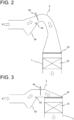
FIG. 2 is a view showing an example of a denitration device according to the present invention. -
FIG. 3 is a view showing another example of the denitration device according to the present invention. -
FIG. 4 is a view showing another example of the denitration device according to the present invention. -
FIG. 5 is a view showing arrangement of soot blowers above a fixed bed of the denitration device shown inFIG. 4 . -
FIG. 6 is a view showing another example of the denitration device according to the present invention. -
FIG. 7 is a view showing arrangement of the soot blowers above the fixed bed of the denitration device shown inFIG. 6 . -
FIG. 8 is a view showing another example of arrangement of the soot blowers above the fixed bed of the denitration device. -
FIG. 9 is a view showing another example of arrangement of the soot blowers above the fixed bed of the denitration device. -
FIG. 10 is a view showing another example of the cement kiln exhaust gas treatment apparatus according to the present invention. -
FIG. 11 is a view showing another example of the cement kiln exhaust gas treatment apparatus according to the present invention. - Embodiments of the present invention will specifically be described with reference to the accompanying drawings. However, the scope of the present invention is not limited by the following embodiments.
- A denitration device according to the present invention includes an
inlet duct 2, adenitration reactor 1, and anoutlet duct 3, and allows an exhaust gas G from a kiln or a furnace to flow to the inlet duct, the denitration reactor, and the outlet duct in this order. - In the inlet duct, the denitration reactor, and the outlet duct, a channel can have, for example, a rectangular, trapezoidal, circular, or elliptical cross-sectional shape as viewed from a gas flow direction. Among these shapes, the rectangular shape is preferred for ease of processing.
- The
inlet duct 2 has on an inlet side a channel where the exhaust gas flows upward, and has on an outlet side a channel where the exhaust gas flows downward. There is practically a horizontally flowing channel between the upward flowing channel and the downward flowing channel, and a wall forming the horizontally flowing channel may directly be connected to an upward wall forming the upward flowing channel and a downward wall forming the downward flowing channel as shown inFIG. 2 , or may be a horizontal wall connected between the upward wall and the downward wall as shown inFIG. 3 . An outlet of theinlet duct 2 is connected to an inlet of thedenitration reactor 1. - A cross-sectional area of the channel disposed between the upward flowing channel and the downward flowing channel is smaller than a cross-sectional area of the upward flowing channel. It is further preferred that the cross-sectional area of the channel disposed between the upward flowing channel and the downward flowing channel be smaller than a cross-sectional area of the downward flowing channel. For example, the cross-sectional area of the upward flowing channel may narrow along a flow direction and the cross-sectional area of the downward flowing channel may widen along the flow direction. As a result, a linear flow velocity increases in the channel disposed between the upward flowing channel and the downward flowing channel, making it possible to suppress dust settling.
- The upward flowing channel is provided with a
hopper 16 in its lower portion. Thehopper 16 increases the cross-sectional area of the upward flowing channel and decreases the linear flow velocity of the exhaust gas, allowing dust to settle easily in the hopper. Further, aweir 15 is disposed around an edge of the hopper on a side near the downward flowing channel. Theweir 15 creates a vortex in a flow of the exhaust gas so that dust easily falls into the hopper, and can also prevent dust that has failed to be removed in the hopper from overflowing into a side of the downward flowing channel. - There may be an additional horizontally flowing channel in front of the upward flowing channel, as needed. The horizontally flowing channel in front of the upward flowing channel is configured to introduce an exhaust gas from a cement kiln, a boiler, etc. into the upward flowing channel.
- The
denitration reactor 1 has a channel through which the exhaust gas flows in a substantially vertical direction. In the denitration reactor, a cross-sectional area of the channel is set such that the exhaust gas flows at a linear flow velocity of 4 to 8 m/sec. - An outlet of the denitration reactor is usually connected to an inlet of the outlet duct.
- In the channel of the denitration reactor, a
screen plate 13 and a fixedbed 12 including a denitration catalyst are disposed in this order along the flow direction. - The
screen plate 13 is usually disposed on an inlet side of the denitration reactor. A structure supporting the screen plate, for example, a beam, etc. passed through in the denitration reactor can be installed on the inlet side of the denitration reactor. The screen plate is supported in the denitration reactor by the screen plate support structure. - The screen plate preferably includes a plurality of slats. The plurality of slats are usually arranged such that their main surfaces are parallel to each other. In order to secure such arrangement of plurality of slats, wires or plate materials (cross members) may be joined to the respective slats along a direction orthogonal to the main surfaces of the respective slats, forming a lattice. Further, outer frame materials (end members) may be disposed at both ends of the plurality of slats.
- The screen plate is preferably installed on the inlet side of the channel of the denitration reactor over an entire channel cross-section such that a long side of the slat is substantially orthogonal to the horizontal gas flow direction in the inlet duct.
- The catalyst fixed
bed 12 is usually disposed on an outlet side of the denitration reactor. A structure supporting the catalyst fixed bed, for example, a beam, etc. passed through in the denitration reactor can be installed on the outlet side of the denitration reactor. The catalyst fixed bed is supported in the denitration reactor by the catalyst fixed bed support structure. Although only a single stage of catalyst fixed bed is disposed inFIG. 2 , multiple stages of catalyst fixed beds may be disposed as necessary. - The fixed bed disposed in the denitration reactor is loaded with a catalyst body in the form of a lattice, corrugated, honeycomb, plate, etc. The catalyst body includes an active component of a denitration catalyst. As an example of the active component of the denitration catalyst, a component (titanium-based catalyst) containing oxides of titanium, oxides of molybdenum and/or tungsten, and oxides of vanadium; a component (zeolite-based catalyst) containing mainly aluminosilicate such as zeolite with a metal such as Cu or Fe supported; and a component obtained by mixing the titanium-based catalyst and the zeolite-based catalyst can be given.
- The fixed bed has an aperture of not less than 7 mm, preferably not less than 10 mm. An upper limit of the aperture is preferably 20 mm. The aperture is a size of an opening in the lattice, corrugated, or honeycomb-shaped catalyst body, and a size of a gap between plates in the plate-shaped catalyst body.
- A
soot blower 14 is disposed in a portion of the inlet duct and/or the denitration reactor, where dust tends to accumulate. - The soot blower is configured to blow an injection medium to blow away adhered dust. For example, water, steam, compressed air (or a pressure wave), etc. is used as the injection medium. A nozzle is installed in a tube called a lance, and the injection medium is ejected from the nozzle. Depending on operation of the lance, the soot blower may be called a reciprocating soot blower, a stationary soot blower, a long-retractable soot blower, a rotary soot blower, etc. A length and shape of the lance, as well as the number of nozzles can be set as appropriate in accordance with a size of the channel in the inlet duct and/or the denitration reactor.
- As one of installation locations of the soot blower, the channel, of the inlet duct, disposed between the upward flowing channel and the downward flowing channel can be given. An injection device for the denitration agent such as ammonia or urea may be disposed here, and thus the injection device and the soot blower may integrally be installed (for example, see
Patent Document - As one of other installation locations of the soot blower, a gas inflow side of the screen plate or the fixed bed in the denitration reactor can be given. Dust tends to adhere to the gas inflow side of the screen plate or the fixed bed. The soot blowers can be arranged in the denitration reactor, for example, as shown in
FIG. 5 ,7, 8, or 9 . It is preferable to arrange lances or nozzles at a high density in a place where dust tends to accumulate (specifically, near a wall, a horizontal portion, etc.). Further, as shown inFIG. 7 , the soot blowers are preferably installed such that a long side of the lance is substantially orthogonal to the horizontal gas flow direction in the inlet duct. Furthermore, as shown inFIG. 9 , asonic horn 17 can be used together. - In the denitration device according to the present invention, the hopper, the weir, and the soot blower disposed in the inlet duct can effectively remove dust from the exhaust gas. In the denitration device according to the present invention, dust hardly accumulates on the screen plate and the fixed bed disposed in the denitration reactor. As a result, it is possible to suppress a decrease in denitration rate due to dust accumulation.
- A cement kiln exhaust gas treatment apparatus according to the present invention includes a
dust collecting device 5 and the denitration device. Thedust collecting device 5 may be disposed upstream of the denitration device as shown inFIG. 1 , or may be disposed downstream of the denitration device as shown inFIG. 11 . The dust collecting device that can be disposed downstream of the denitration device can be an electric dust precipitator for low-temperature gas. The electric dust precipitator for low-temperature gas is less expensive than an electric dust precipitator for high-temperature gas in terms of a facility cost. - Further, a cement kiln exhaust gas treatment apparatus according to the present invention preferably further includes a waste heat recovery boiler. A waste
heat recovery boiler 18 may be disposed upstream of the denitration device, or may be disposed downstream of the denitration device as shown inFIG. 11 . The wasteheat recovery boiler 18 and thedust collecting device 5 may be arranged in the order shown inFIG. 11 , or may be arranged in a reverse order. Heat can effectively be utilized by the waste heat recovery boiler. Steam generated by the boiler can also be used as the injection medium for the soot blower. -
- 1:
- Denitration reactor
- 2:
- Inlet dust
- 3:
- Outlet dust
- 4:
- Denitration agent addition device
- 5:
- Dust collecting device
- 6:
- Cement raw material
- 7:
- Calciner
- 8:
- Cement kiln
- 9:
- Clinker cooler
- 10:
- Stack
- 11:
- Preheater
- 12:
- Catalyst fixed bed
- 13:
- Screen plate
- 14:
- Soot blower
- 15:
- Weir
- 16:
- Hopper
- 17:
- Sonic horn
- 18:
- Waste heat recovery boiler
- G:
- Exhaust gas
Claims (4)
- A denitration device, comprising:an inlet duct; a denitration reactor; and an outlet duct,wherein the denitration device allows an exhaust gas from a kiln or a furnace to flow to the inlet duct, the denitration reactor, and the outlet duct in this order,wherein the denitration reactor has a channel through which the exhaust gas flows at a linear flow velocity of 5 to 8 m/sec in a substantially vertical direction, the channel is internally provided with a screen plate and a fixed bed including a denitration catalyst in this order along a flow direction, and the fixed bed has an aperture of not less than 7 mm,wherein the inlet duct has on an inlet side a channel where the exhaust gas flows upward and has on an outlet side a channel where the exhaust gas flows downward, a cross-sectional area of a channel between the upward flowing channel and the downward flowing channel is smaller than a cross-sectional area of the upward flowing channel, a hopper is disposed in a lower portion of the upward flowing channel, and a weir is disposed around an edge of the hopper on a side near the downward flowing channel, andwherein a soot blower is disposed in a portion of the inlet duct and/or the denitration reactor, where dust tends to accumulate.
- A cement kiln exhaust gas treatment apparatus, comprising:a dust collecting device for collecting dust in a cement kiln exhaust gas; andthe denitration device according to claim 1 for removing nitrogen oxides in the cement kiln exhaust gas,wherein the cement kiln exhaust gas treatment apparatus allows an exhaust gas from a cement kiln to flow to the dust collecting device and the denitration device in this order.
- A cement kiln exhaust gas treatment apparatus, comprising:the denitration device according to claim 1 for removing nitrogen oxides in a cement kiln exhaust gas; anda dust collecting device for collecting dust in the cement kiln exhaust gas,wherein the cement kiln exhaust gas treatment apparatus allows an exhaust gas from a cement kiln to flow to the denitration device and the dust collecting device in this order.
- The cement kiln exhaust gas treatment apparatus according to claim 2 or 3, further comprising:
a waste heat recovery boiler for recovering heat of the exhaust gas, on a downstream side of the denitration device.
Applications Claiming Priority (1)
| Application Number | Priority Date | Filing Date | Title |
|---|---|---|---|
| PCT/JP2021/035690 WO2023053218A1 (en) | 2021-09-28 | 2021-09-28 | Denitration device |
Publications (3)
| Publication Number | Publication Date |
|---|---|
| EP4378565A1 true EP4378565A1 (en) | 2024-06-05 |
| EP4378565A4 EP4378565A4 (en) | 2024-07-31 |
| EP4378565B1 EP4378565B1 (en) | 2026-01-28 |
Family
ID=85781477
Family Applications (1)
| Application Number | Title | Priority Date | Filing Date |
|---|---|---|---|
| EP21959266.4A Active EP4378565B1 (en) | 2021-09-28 | 2021-09-28 | Denitration device |
Country Status (3)
| Country | Link |
|---|---|
| EP (1) | EP4378565B1 (en) |
| CN (1) | CN117813146A (en) |
| WO (1) | WO2023053218A1 (en) |
Families Citing this family (2)
| Publication number | Priority date | Publication date | Assignee | Title |
|---|---|---|---|---|
| BE1032414B1 (en) * | 2024-02-22 | 2025-09-23 | Maerz Ofenbau | Exhaust gas purification device and a cement production plant with an exhaust gas purification device |
| CN121338435B (en) * | 2025-09-23 | 2026-06-26 | 江苏宝净环境科技有限公司 | A device for dry desulfurization coupled with high-efficiency dust removal and denitrification of flue gas from biomass boilers. |
Family Cites Families (18)
| Publication number | Priority date | Publication date | Assignee | Title |
|---|---|---|---|---|
| JPS6057117A (en) | 1983-09-09 | 1985-04-02 | Mitsubishi Heavy Ind Ltd | Ash dispersing nozzle structure |
| JP2724176B2 (en) * | 1988-09-30 | 1998-03-09 | バブコツク日立株式会社 | Exhaust gas denitration equipment |
| JP2005207697A (en) * | 2004-01-26 | 2005-08-04 | Ebara Corp | Exhaust gas treatment method and device for fusion furnace |
| KR101207958B1 (en) | 2005-01-06 | 2012-12-04 | 가부시키가이샤 닛폰 쇼쿠바이 | Cement kiln firing waste gas treating apparatus and treating method |
| JP5284722B2 (en) | 2008-08-20 | 2013-09-11 | バブコック日立株式会社 | Flue gas denitration equipment |
| JP2010054083A (en) | 2008-08-26 | 2010-03-11 | Babcock Hitachi Kk | Denitration device |
| JP5877578B2 (en) * | 2011-10-24 | 2016-03-08 | 太平洋セメント株式会社 | Combustion exhaust gas treatment apparatus and treatment method |
| JP5912638B2 (en) | 2012-02-20 | 2016-04-27 | 太平洋セメント株式会社 | Cement kiln exhaust gas treatment apparatus and treatment method |
| CN102989315A (en) * | 2012-12-12 | 2013-03-27 | 山东大学 | Deashing device for SCR flue gas denitration system |
| JP6338323B2 (en) * | 2013-05-31 | 2018-06-06 | 三菱日立パワーシステムズ株式会社 | Denitration equipment |
| JP6560007B2 (en) | 2015-04-08 | 2019-08-14 | 三菱日立パワーシステムズ株式会社 | Exhaust gas treatment equipment |
| CN107970772B (en) * | 2017-12-27 | 2024-03-08 | 福建龙净环保股份有限公司 | SCR flue gas denitrification facility |
| JP2019147142A (en) | 2018-02-28 | 2019-09-05 | 三菱日立パワーシステムズ株式会社 | Exhaust gas treatment device |
| CN109731462A (en) | 2018-05-31 | 2019-05-10 | 安徽海螺建材设计研究院有限责任公司 | A flue gas nitrogen oxide treatment system |
| JP7261019B2 (en) * | 2019-01-21 | 2023-04-19 | 三菱重工業株式会社 | Denitration equipment |
| JP7391651B2 (en) * | 2019-12-13 | 2023-12-05 | 三菱重工業株式会社 | Denitrification equipment, boiler system, and installation method of denitrification equipment |
| JP7603385B2 (en) * | 2020-06-30 | 2024-12-20 | 三菱重工業株式会社 | Denitrification equipment and cement kiln exhaust gas treatment equipment |
| CN112138542B (en) * | 2020-10-13 | 2024-10-29 | 南京依涛环保科技有限公司 | A high-temperature flue gas dust removal, denitrification and desulfurization system and method |
-
2021
- 2021-09-28 WO PCT/JP2021/035690 patent/WO2023053218A1/en not_active Ceased
- 2021-09-28 CN CN202180101530.3A patent/CN117813146A/en active Pending
- 2021-09-28 EP EP21959266.4A patent/EP4378565B1/en active Active
Also Published As
| Publication number | Publication date |
|---|---|
| EP4378565B1 (en) | 2026-01-28 |
| WO2023053218A1 (en) | 2023-04-06 |
| CN117813146A (en) | 2024-04-02 |
| EP4378565A4 (en) | 2024-07-31 |
Similar Documents
| Publication | Publication Date | Title |
|---|---|---|
| US9283520B2 (en) | Exhaust gas treatment apparatus | |
| US6156277A (en) | Exhaust gas cleaning plant for a cement rotary kiln | |
| EP2289608B1 (en) | System and method for protecting a scr catalyst from large particle ash | |
| KR101245198B1 (en) | Integrated removal apparatus for removing fine particulate and nitrogen oxide | |
| US4307068A (en) | Method and apparatus for treating an exhaust gas | |
| EP4378565B1 (en) | Denitration device | |
| CN107970772B (en) | SCR flue gas denitrification facility | |
| EP2979761A1 (en) | Method for regenerating denitrification catalyst | |
| JP2724176B2 (en) | Exhaust gas denitration equipment | |
| WO2017179107A1 (en) | Exhaust gas processing system | |
| JP4858727B2 (en) | Flue gas denitration equipment | |
| EP3423191B1 (en) | Gas dedusting filter apparatus and process | |
| JP7603385B2 (en) | Denitrification equipment and cement kiln exhaust gas treatment equipment | |
| US20240390834A1 (en) | System, method, and apparatus for ameliorating deposits in selective catalytic reduction systems for the reduction of nitrogen oxide emissions in steam methane reformers | |
| EP3507544B1 (en) | Scr-system for removing ash from a flue gas stream generated in a combustion system | |
| KR100844288B1 (en) | Method and device for the separation of dust particles | |
| JP2008126148A (en) | Exhaust gas denitration device | |
| JP3362212B2 (en) | Catalytic denitration equipment | |
| CN212855245U (en) | SCR catalysis dry-method denitration desulfurization system | |
| CN117942756A (en) | Integrated device for dust removal and denitrification of cement kilns | |
| KR20030067572A (en) | Reactor for catalytic treatment of a particle-containing gas |
Legal Events
| Date | Code | Title | Description |
|---|---|---|---|
| STAA | Information on the status of an ep patent application or granted ep patent |
Free format text: STATUS: THE INTERNATIONAL PUBLICATION HAS BEEN MADE |
|
| PUAI | Public reference made under article 153(3) epc to a published international application that has entered the european phase |
Free format text: ORIGINAL CODE: 0009012 |
|
| STAA | Information on the status of an ep patent application or granted ep patent |
Free format text: STATUS: REQUEST FOR EXAMINATION WAS MADE |
|
| 17P | Request for examination filed |
Effective date: 20240228 |
|
| AK | Designated contracting states |
Kind code of ref document: A1 Designated state(s): AL AT BE BG CH CY CZ DE DK EE ES FI FR GB GR HR HU IE IS IT LI LT LU LV MC MK MT NL NO PL PT RO RS SE SI SK SM TR |
|
| A4 | Supplementary search report drawn up and despatched |
Effective date: 20240701 |
|
| RIC1 | Information provided on ipc code assigned before grant |
Ipc: C01B 21/20 20060101ALI20240625BHEP Ipc: B01D 45/08 20060101ALI20240625BHEP Ipc: B01D 53/86 20060101AFI20240625BHEP |
|
| DAV | Request for validation of the european patent (deleted) | ||
| DAX | Request for extension of the european patent (deleted) | ||
| GRAP | Despatch of communication of intention to grant a patent |
Free format text: ORIGINAL CODE: EPIDOSNIGR1 |
|
| STAA | Information on the status of an ep patent application or granted ep patent |
Free format text: STATUS: GRANT OF PATENT IS INTENDED |
|
| INTG | Intention to grant announced |
Effective date: 20250822 |
|
| GRAS | Grant fee paid |
Free format text: ORIGINAL CODE: EPIDOSNIGR3 |
|
| GRAA | (expected) grant |
Free format text: ORIGINAL CODE: 0009210 |
|
| STAA | Information on the status of an ep patent application or granted ep patent |
Free format text: STATUS: THE PATENT HAS BEEN GRANTED |
|
| AK | Designated contracting states |
Kind code of ref document: B1 Designated state(s): AL AT BE BG CH CY CZ DE DK EE ES FI FR GB GR HR HU IE IS IT LI LT LU LV MC MK MT NL NO PL PT RO RS SE SI SK SM TR |
|
| REG | Reference to a national code |
Ref country code: CH Ref legal event code: F10 Free format text: ST27 STATUS EVENT CODE: U-0-0-F10-F00 (AS PROVIDED BY THE NATIONAL OFFICE) Effective date: 20260128 Ref country code: GB Ref legal event code: FG4D |
|
| REG | Reference to a national code |
Ref country code: DE Ref legal event code: R096 Ref document number: 602021047446 Country of ref document: DE |
|
| REG | Reference to a national code |
Ref country code: IE Ref legal event code: FG4D |
|
| REG | Reference to a national code |
Ref country code: NL Ref legal event code: MP Effective date: 20260128 |
|
| PG25 | Lapsed in a contracting state [announced via postgrant information from national office to epo] |
Ref country code: NL Free format text: LAPSE BECAUSE OF FAILURE TO SUBMIT A TRANSLATION OF THE DESCRIPTION OR TO PAY THE FEE WITHIN THE PRESCRIBED TIME-LIMIT Effective date: 20260128 |
|
| REG | Reference to a national code |
Ref country code: AT Ref legal event code: MK05 Ref document number: 1880487 Country of ref document: AT Kind code of ref document: T Effective date: 20260128 |
|
| PG25 | Lapsed in a contracting state [announced via postgrant information from national office to epo] |
Ref country code: RS Free format text: LAPSE BECAUSE OF FAILURE TO SUBMIT A TRANSLATION OF THE DESCRIPTION OR TO PAY THE FEE WITHIN THE PRESCRIBED TIME-LIMIT Effective date: 20260428 |
|
| PG25 | Lapsed in a contracting state [announced via postgrant information from national office to epo] |
Ref country code: ES Free format text: LAPSE BECAUSE OF FAILURE TO SUBMIT A TRANSLATION OF THE DESCRIPTION OR TO PAY THE FEE WITHIN THE PRESCRIBED TIME-LIMIT Effective date: 20260128 |
|
| PG25 | Lapsed in a contracting state [announced via postgrant information from national office to epo] |
Ref country code: PL Free format text: LAPSE BECAUSE OF FAILURE TO SUBMIT A TRANSLATION OF THE DESCRIPTION OR TO PAY THE FEE WITHIN THE PRESCRIBED TIME-LIMIT Effective date: 20260128 |
|
| PG25 | Lapsed in a contracting state [announced via postgrant information from national office to epo] |
Ref country code: GR Free format text: LAPSE BECAUSE OF FAILURE TO SUBMIT A TRANSLATION OF THE DESCRIPTION OR TO PAY THE FEE WITHIN THE PRESCRIBED TIME-LIMIT Effective date: 20260429 |
|
| REG | Reference to a national code |
Ref country code: LT Ref legal event code: MG9D |
|
| PG25 | Lapsed in a contracting state [announced via postgrant information from national office to epo] |
Ref country code: LT Free format text: LAPSE BECAUSE OF FAILURE TO SUBMIT A TRANSLATION OF THE DESCRIPTION OR TO PAY THE FEE WITHIN THE PRESCRIBED TIME-LIMIT Effective date: 20260128 |
|
| PG25 | Lapsed in a contracting state [announced via postgrant information from national office to epo] |
Ref country code: NO Free format text: LAPSE BECAUSE OF FAILURE TO SUBMIT A TRANSLATION OF THE DESCRIPTION OR TO PAY THE FEE WITHIN THE PRESCRIBED TIME-LIMIT Effective date: 20260428 |
|
| PG25 | Lapsed in a contracting state [announced via postgrant information from national office to epo] |
Ref country code: FI Free format text: LAPSE BECAUSE OF FAILURE TO SUBMIT A TRANSLATION OF THE DESCRIPTION OR TO PAY THE FEE WITHIN THE PRESCRIBED TIME-LIMIT Effective date: 20260128 Ref country code: SE Free format text: LAPSE BECAUSE OF FAILURE TO SUBMIT A TRANSLATION OF THE DESCRIPTION OR TO PAY THE FEE WITHIN THE PRESCRIBED TIME-LIMIT Effective date: 20260128 Ref country code: AT Free format text: LAPSE BECAUSE OF FAILURE TO SUBMIT A TRANSLATION OF THE DESCRIPTION OR TO PAY THE FEE WITHIN THE PRESCRIBED TIME-LIMIT Effective date: 20260128 |
|
| PG25 | Lapsed in a contracting state [announced via postgrant information from national office to epo] |
Ref country code: HR Free format text: LAPSE BECAUSE OF FAILURE TO SUBMIT A TRANSLATION OF THE DESCRIPTION OR TO PAY THE FEE WITHIN THE PRESCRIBED TIME-LIMIT Effective date: 20260128 |
|
| PG25 | Lapsed in a contracting state [announced via postgrant information from national office to epo] |
Ref country code: IS Free format text: LAPSE BECAUSE OF FAILURE TO SUBMIT A TRANSLATION OF THE DESCRIPTION OR TO PAY THE FEE WITHIN THE PRESCRIBED TIME-LIMIT Effective date: 20260528 Ref country code: PT Free format text: LAPSE BECAUSE OF FAILURE TO SUBMIT A TRANSLATION OF THE DESCRIPTION OR TO PAY THE FEE WITHIN THE PRESCRIBED TIME-LIMIT Effective date: 20260528 |
|
| PG25 | Lapsed in a contracting state [announced via postgrant information from national office to epo] |
Ref country code: LV Free format text: LAPSE BECAUSE OF FAILURE TO SUBMIT A TRANSLATION OF THE DESCRIPTION OR TO PAY THE FEE WITHIN THE PRESCRIBED TIME-LIMIT Effective date: 20260128 |
|
| PG25 | Lapsed in a contracting state [announced via postgrant information from national office to epo] |
Ref country code: BG Free format text: LAPSE BECAUSE OF FAILURE TO SUBMIT A TRANSLATION OF THE DESCRIPTION OR TO PAY THE FEE WITHIN THE PRESCRIBED TIME-LIMIT Effective date: 20260128 |