EP4377992B1 - Process shutter arrangement - Google Patents
Process shutter arrangement Download PDFInfo
- Publication number
- EP4377992B1 EP4377992B1 EP22750674.8A EP22750674A EP4377992B1 EP 4377992 B1 EP4377992 B1 EP 4377992B1 EP 22750674 A EP22750674 A EP 22750674A EP 4377992 B1 EP4377992 B1 EP 4377992B1
- Authority
- EP
- European Patent Office
- Prior art keywords
- disc
- arm
- sickle
- shutter
- chuck
- Prior art date
- Legal status (The legal status is an assumption and is not a legal conclusion. Google has not performed a legal analysis and makes no representation as to the accuracy of the status listed.)
- Active
Links
Images



Classifications
-
- H—ELECTRICITY
- H01—ELECTRIC ELEMENTS
- H01J—ELECTRIC DISCHARGE TUBES OR DISCHARGE LAMPS
- H01J37/00—Discharge tubes with provision for introducing objects or material to be exposed to the discharge, e.g. for the purpose of examination or processing thereof
- H01J37/32—Gas-filled discharge tubes
- H01J37/34—Gas-filled discharge tubes operating with cathodic sputtering
- H01J37/3411—Constructional aspects of the reactor
- H01J37/3447—Collimators, shutters, apertures
-
- H—ELECTRICITY
- H10—SEMICONDUCTOR DEVICES; ELECTRIC SOLID-STATE DEVICES NOT OTHERWISE PROVIDED FOR
- H10P—GENERIC PROCESSES OR APPARATUS FOR THE MANUFACTURE OR TREATMENT OF DEVICES COVERED BY CLASS H10
- H10P72/00—Handling or holding of wafers, substrates or devices during manufacture or treatment thereof
- H10P72/04—Apparatus for manufacture or treatment
- H10P72/0451—Apparatus for manufacturing or treating in a plurality of work-stations
- H10P72/0462—Apparatus for manufacturing or treating in a plurality of work-stations characterised by the construction of the processing chambers, e.g. modular processing chambers
-
- H—ELECTRICITY
- H10—SEMICONDUCTOR DEVICES; ELECTRIC SOLID-STATE DEVICES NOT OTHERWISE PROVIDED FOR
- H10P—GENERIC PROCESSES OR APPARATUS FOR THE MANUFACTURE OR TREATMENT OF DEVICES COVERED BY CLASS H10
- H10P72/00—Handling or holding of wafers, substrates or devices during manufacture or treatment thereof
- H10P72/70—Handling or holding of wafers, substrates or devices during manufacture or treatment thereof for supporting or gripping
- H10P72/76—Handling or holding of wafers, substrates or devices during manufacture or treatment thereof for supporting or gripping using mechanical means, e.g. clamps or pinches
- H10P72/7604—Handling or holding of wafers, substrates or devices during manufacture or treatment thereof for supporting or gripping using mechanical means, e.g. clamps or pinches the wafers being placed on a susceptor, stage or support
- H10P72/7612—Handling or holding of wafers, substrates or devices during manufacture or treatment thereof for supporting or gripping using mechanical means, e.g. clamps or pinches the wafers being placed on a susceptor, stage or support characterised by lifting arrangements, e.g. lift pins
-
- H—ELECTRICITY
- H10—SEMICONDUCTOR DEVICES; ELECTRIC SOLID-STATE DEVICES NOT OTHERWISE PROVIDED FOR
- H10P—GENERIC PROCESSES OR APPARATUS FOR THE MANUFACTURE OR TREATMENT OF DEVICES COVERED BY CLASS H10
- H10P72/00—Handling or holding of wafers, substrates or devices during manufacture or treatment thereof
- H10P72/70—Handling or holding of wafers, substrates or devices during manufacture or treatment thereof for supporting or gripping
- H10P72/76—Handling or holding of wafers, substrates or devices during manufacture or treatment thereof for supporting or gripping using mechanical means, e.g. clamps or pinches
- H10P72/7604—Handling or holding of wafers, substrates or devices during manufacture or treatment thereof for supporting or gripping using mechanical means, e.g. clamps or pinches the wafers being placed on a susceptor, stage or support
- H10P72/7624—Handling or holding of wafers, substrates or devices during manufacture or treatment thereof for supporting or gripping using mechanical means, e.g. clamps or pinches the wafers being placed on a susceptor, stage or support characterised by the mechanical construction of the susceptor, stage or support
Definitions
- the invention refers to a process shutter arrangement according to claim 1, to a shutter disc according to claim 9, to a shutter arm according to claim 11, to a vacuum process system according to claim 12, and to a method to use a process shutter arrangement according to claim 14.
- Process shutter arrangements comprising a shutter disc, also known as dummy disc as it replaces a wafer which is usually processed on the chuck, and a shutter arm to rotate the disc from a niche of the processing chamber or a separate compartment towards a pedestal or chuck, which carries the wafer or other substrates during processing, are widely used in vacuum equipment for semiconductor and optical industries, for instance for conditioning or pasting processes to extend the replacement cycle of the process shields, or simply to cover the top of a chuck to protect it against dust or mechanical exposure during servicing. As such equipment is expensive and highly automized, service intervals should be minimized, and precision and reliability of any step be optimized. Due to shorter process times and respective high number of process cycles, a higher number of conditioning and/or pasting operations per time unit follows.
- a dummy or shutter disc is a disc to replace a wafer in a processing position during a servicing, a conditioning, or a pasting step to protect the underlying equipment, especially the highly sensitive wafer bearing surface of the chuck.
- the disc should be able to receive a considerable amount of deposition material from the targets in case of target sputtering in the process chamber or allow a considerable amount of material to be removed when etching is performed during a so called conditioning or pasting step.
- different sputter or conditioning/ pasting steps shall be performed, usually different discs will be used for sputtering or conditioning/pasting steps.
- a shutter sickle is the part of a shutter arm which carries the shutter disc and is provided at least with the positioning tenons.
- the sickle can essentially have the form of a sickle, however, can be also disc or paddle like itself and having slots to let the pins of the chuck pass during rotational movement to and from a center position over the chuck. Therefore, the inner periphery of the sickle D Si can define an actual periphery of the sickle or the innermost position of at least one of the tenons, which preferably sit in a position having essentially the same distance from the center of the sickle.
- the bearing surface may extend radially from the inner periphery D Si of the sickle, e.g. in an outward direction and/or in a center direction.
- the tenons being positioned near or adjacent to the inner diameter D Si .
- the disc may further comprise a circumferential rim extending in a horizontally sidewise direction and/or in a vertically downward direction.
- the mortises can be arranged within an inner diameter D Ri of the rim or within a projection of the inner positioning rim, and adjacent, e.g., immediately adjacent, to the rim or the projection.
- Mortises may have a basic rectangular geometry.
- the material or the coating respectively plating of the disc can be chosen. If only a coating or plating of the disc is provided, at least the second side of the disc should be coated or plated and, if not protected by a clamp or holder on the chuck during the pasting or conditioning step, the second side of the rim, and the periphery of the disc respectively rim.
- ceramic can be any densely sintered ceramic, e.g., aluminum oxide, silicon nitride or silicon carbide. If, however a pasting process should be performed, a respective pasting material like titanium or aluminum can be used as well as more exotic pasting materials like ZrFe or Pt.
- An inventive shutter arm may comprise a sidewall to enhance the stiffness of the sickle when space is limited.
- the sidewall may form at least in part an outer periphery D So of the sickle, whereat the outer diameter D Do of the disc fits into the inner periphery D Wi of the sidewall.
- the chuck dimension relates directly to the size of a wafer to be treated in a vacuum process which can be PVD, a CVD or an etch process as an example. With reference to the disc to chuck relation to be treated at the chuck, as an example for a disc having a flat first side as shown in Fig.2 below, a very small or even no oversize will suffice.
- a disc with a rim having a vertical extension over the first surface as shown in Fig.3 .
- a few millimeters may be added for the rim in a radially outwards direction of the the wafer bearing surface, whereas a few tenth of a millimeter for the vertical extension suffice to avoid touching of an all flat wafer bearing surface of a chuck by the disc.
- the sidewall of the sickle may encompass the bearing surface in an angular range of about180° or smaller and can be a continuous or a interrupted sidewall, e.g. a sequence of pins.
- the bearing surface of the sickle may extend over an angular range of 180° - 360° and will be usually of 230 ⁇ 30° of the inner diameter D Si .
- Tenons may have a basic rectangular, a circular or an oval geometry and have to be symmetrically with reference to a middle plane extending along an axes ⁇ 1-3 and the height direction z of a tenon.
- Tenons have a rectangular or square base, round corners or a circular end geometry will be usually provided.
- the disc may further comprise a flat and/or a notch at or in its outer diameter D Do , and the sickle may comprise a corresponding flat side and/or a nib, e.g., at the inner diameter D Wi of the side wall.
- the chuck to be protected has respective positioning nibs or flat sides for the wafer to be processed.
- the shutter arm can be made of a material having an elastic modulus of at least 100 to 500 GPa to provide a high stiffness and avoid disturbing vibrations.
- densely sintered ceramic materials like aluminum oxide, silicon nitride, or silicon carbide are preferred due to their light weight.
- tenons and mortises can be reversed, which means that tenons can be provided at the first surface of the disc and mortises can be provided at the bearing surface of the sickle.
- the mortises having further a short dimension b, and a depth dimension d, where b ⁇ a.
- It is a further objective of the present invention to provide a shutter arm comprising a shaft with mounting means, a bearing sickle with an inner periphery D Si , and at least three positioning tenons near or adjacent to the inner diameter D Si , being in operative connection with positioning mortises to position the disc when set on the positioning tenons or on an optional bearing surface of the sickle.
- the disc may sit directly on the bearing surface or on top of the tenons, depending on the height of the tenons and respective depth of the mortises and the provision of a bearing surface.
- the bearing surface may extend radially from the inner periphery D Si of the sickle, e.g., in an outward direction and/or in a center direction.
- the tenons being positioned near or adjacent to the inner diameter D Si .
- the shutter arm further comprising a shaft with mounting means for the bearing sickle with a bearing surface radially extending from an inner periphery D Si of the sickle, and optionally a semi-circumferential side wall encompassing the bearing surface.
- mortises and tenons When the disc is mounted on the bearing surface of the sickle or on top of the tenons, tenons rest in respective mortises. Therefore, angular orientation and radial position of mortises and tenons has to be the same. As mentioned above mortises and tenons may be interchanged from the disc to the arm respectively vice-versa.
- positioning means which may be provided on the chuck to position wafers having a notch or a flat respective positioning means like a flat and a flat side, a notch and a nib, can be foreseen with the disc which replaces the wafer for the servicing, conditioning or pasting step, and the sickle to bear the respective disk.
- flats and/or notches may be provided at or in the outer diameter D Do of the disc, whereat the flat side and/or the nib may be provided at the inner periphery D Wi of the sidewall.
- It is a further objective of the present invention to provide a vacuum process system comprising a vacuum process chamber which houses a chuck with pins being movably mounted in a z-direction to a pin drive and a process shutter arrangement as discussed above and will be further discussed at the hand of the figures below.
- the arm of the process shutter arrangement is mounted to a vacuum side of a rod having a vertical rotational axis R, the rod being mounted to the chamber by a feedthrough, and being in operative connection with a shutter drive at the atmosphere side of the rod, to rotate the arm in a horizontal plane from a niche of the processing chamber or a separate compartment in a central position over the chuck, to enable that the pins of the chuck take over the disc.
- the pin drive of the chuck may be mounted to the process chamber, on atmosphere side or on the vacuum side.
- the drive may extend the pins in a uniform joint movement in an upper end position which can be between 5 and 30, e.g. 10 to 20 mm above the horizontal top of the chuck. Therefore, pins have to be provided within the inner diameter D Si of the sickle, when the latter is in the central position.
- the process system may further comprise a control unit connected to the pin drive and the shutter drive to coordinate rotational movement of the arm and linear z-movement of the pins to rotate the arm with the disc and lift and lower the disc when the arm is in the central position.
- the chuck of the process system can be a static chuck or a dynamic chuck which can be moved in a vertical direction from a loading position into a processing position and vice-versa.
- a handling cut-out in the process shields with a drivingly movable screen-shutter can be provided, when only a niche for the rest or idle position of the sickle is foreseen.
- a disc handling opening can be provided with a respective lock in the chamber wall when a separate compartment should be foreseen.
- Disc handling cut-out and disc handling opening being mutually aligned and tailored to allow handling of a plate shaped disc. This can be in analogy to the substrate handling arrangement as disclosed in WO 2017/215806 of the same applicant. Special reference is made to Fig.1 and respective description.
- Opening and closing of the handling cut-out in the process shields in this case can be performed by at least two telescopic cylindric shields encompassing the outer diameter of the chuck, whereat one of the shields is mounted to and moves with the chuck, whereby respective cut-outs are opened or closed by the respective other shield.
- the Method may further comprise the following steps:
- the components and relevant functional principles of a process system operating in a conditioning or pasting mode are shown at the hand of Fig.1 .
- the exemplary process system 30 as shown has a vacuum pump 32 attached to the vacuum chamber 31 which houses a chuck 20 to process wafers or other flat substrates and an inventive process shutter arrangement consisting of a shutter disc 1 and a shutter arm 10.
- the shutter arm is mounted to the rod 26 of a shutter drive 28 to rotate the shutter disc from a niche 34 of the processing chamber 31 or a separate compartment 34 in a central position over the chuck.
- the rod runs through a vacuum feedthrough 27.
- pins 21 lift the shutter disc 1 in z-direction according to the double arrows from the bearing surface 12 of the sickle 11.
- pins 21 can be the pins as used to lift a wafer from a wafer blade. Thereafter the sickle 11 is rotated back into the niche 34 or separate chamber 34 and pins are retracted in the chuck surface to position the disc on the chuck to protect its surface during a following conditioning, pasting process or servicing operation.
- the present shutter disc and shutter arm can be designed extremely flat, so that only a short lift is necessary to enable the back-rotation of the arm with the disc unloaded from the sickle 11.
- the control unit 31 can be used to trigger and control respective rotational movement of the arm 10 and vertical movement of the pins 21, which can be initiated by an operator for service or by the system control (not shown) to which the control unit 31 may be integrated.
- the pin drive 22 which can be positioned on the atmosphere or the vacuum side of the process chamber 31, which also houses the pin transmission and further components (not shown) used for the operation of the chuck.
- the picking up of the disc by the sickle of the arm is supported by respective positioning features on the disc and sickle. So, when the disc is lowered by retraction of the pins towards the sickle and pins 21 are further retracted in a position at least below the bearing surface 12, precision positioning is completed by three positioning tenons 14 in the sickle surface 12 which enter into the respective mortises 4 in the lower disc surface 2, whereby the position of the disc 1 is perfectly defined on the bearing surface 12 of the sickle 11 before it is rotated back in rest position. Therewith for the next conditioning or pasting operation the shutter drive can rotate the arm with the disc in position above the chuck and handover the disc to the pins at the very right place without further measures.
- vacuum process systems as shown in Fig.1 usually will have additional features like gas inlets for PVD or CVD processes, sputtering targets to deposit materials, etching devices or the like to process a wafer or other flat substrates, which only makes conditioning, pasting or service cycles necessary.
- gas inlets for PVD or CVD processes sputtering targets to deposit materials, etching devices or the like to process a wafer or other flat substrates, which only makes conditioning, pasting or service cycles necessary.
- sputtering targets to deposit materials, etching devices or the like to process a wafer or other flat substrates
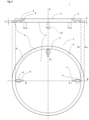
- a shutter disc 1 with three positioning mortises 4 in a first surface 2 and a rim 6 optionally provided with a flat 8 and/or a notch 9 is shown in Fig.2 .
- the shutter disc having a thickness t, the mortises having a length a, a width b, and a depth d (see also Fig.3 ) and being positioned with their longitudinal axes ⁇ 1-3 radially in a peripheral position at 0°, 90° and 180° of the disc perimeter.
- the disc also comprises three nicks 5 in a second surface 3 of the disc 1, positioned on an inner extension of the projection of axes ⁇ 1-3 , adjacent to mortises 4. These nicks can be used for a first placing step, e.g.
- Mortises can have a circumferential bevel 4' and tenons can have a circumferential chamfer 14', each alone or in cooperation with each other to ease matching of the two positioning elements.
- Mortises 4 can be positioned on axis ⁇ 1-3 in parallel and symmetric to it as indicated in solid lines, or alternatively right angled to axis ⁇ 1-3 as indicated in dashed lines and reference number 4", which will usually be also symmetric as referred to before.
- a similar shutter disc 1 with three positioning mortises 4 in the first surface 2 and a rim 6 here provided with a flat 8 is shown.
- the rim 6 also has a vertical extension which slightly towers over the first surface 2 and thereby may encompass the wafer bearing surface of the chuck 20 and sit on a peripheral chuck surface.
- the disks as shown in Fig.2 and Fig.3 can be designed very flat with a thickness t from 2 to 20 mm, or 3 to 10 mm
- the provision of a rim 6 of lower thickness t R can make it easy to clamp the disc on the chuck with usual wafer clamps, e.g. during sputtering processes.
- the rim 6 can be small but at the same time wide enough to provide place for the positioning flat 8 or notch 9.
- disc dimensions for a 300 mm chuck which are usual chuck dimensions to process 300 mm wafers, can be: 300.2 ⁇ D DO ⁇ 305 mm , 293 ⁇ D Ri ⁇ 298 mm .
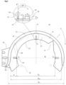
- a shutter disk arm 10 which can be mounted to the rod 26 of a rotation unit by a shaft 15 with flange and positioning slots 16 to level the sickle is shown in Fig.4 .
- a central mounting on the shaft as shown in Fig.1 , can be foreseen.
- the arm 10 further comprises a sickle 11 with a bearing surface 12 and sidewall 13.
- Three positioning tenants 14, each offset by 90° from the next tenant, are placed on the bearing surface 11 next to the inner diameter of the sickle, with their axes ⁇ 1-3 arranged radially towards the inner periphery of the sickle D Si .
- axes ⁇ 1-3 of mortises 4 and axes ⁇ 1-3 of the tenants 14 coincide and the inner periphery D Wi of the sidewall 13 encompasses the outer diameter D Do of the disc 1 on the bearing surface 12.
- the long dimension a of the mortise 4 should be provided considerably longer than the respective dimension m of the tenant 14 to enable thermal compensation.
- the difference should be at least 1 to 3 mm, depending on the maximal thermal load during processing.
- a flat side 8' and/or a nib 9' can be foreseen as shown in dashed lines.
- Reference number 17 refers to an optional out-cut to allow an optical sensor (not shown), to acknowledge correct positioning of the disc.
- the optical sensor can be mounted in a niche or a separate rest chamber for the arm and disc or can be integrated on the arm 10.
- One or more openings 18 as shown in dotted lines may be provided in the bearing surface 11 and a lower part of the side wall 13 to allow protrusions from the chuck or pins positioned further outward on the chuck to pass.
- Width w of the bearing surface should be from at least about 1.5 the length m of a tenon till about 30 mm to allow pins 21 to pass inside when lifting the disc 1.
- the magnifying glass in the upper part of the drawing shows on the left side a view from the center of the sickle 11 towards a tenant 14 on the bearing surface 12 and a sideview in a 90° perspective to the left side.
- Tenants may have a maximal length dimension m, a maximal width dimension n, and a height h whereby: 2 ⁇ m ⁇ 20 mm 2 ⁇ n ⁇ 20 mm 1 ⁇ h ⁇ 10 mm .
- mortises having a maximal length dimension a and a maximal width dimension b can be used with the following dimensions: 2 ⁇ a ⁇ 20 mm 2 ⁇ b ⁇ 20 mm 1 ⁇ d ⁇ 10 mm .
- Fig.5 shows further details of a positioning tenant 14 in top view.
- the tenant 14 comprising two circular edge sections of radius r, a straight middle part here of length l, and an upper finish with a circumferential chamfer 14'.
- r can be 2 mm and height h of the tenant can be also 2 mm.
- round tenants, tenants with an oval base or other convenient base forms as known to the man skilled in the art can be used.
- FIG.6 A further embodiment of an inventive shutter arm is shown in Fig.6 .
- circular tenons 14, mounted on an inner end of cantilevers 19, are used to position and hold the respective disc, which means the disc sits on the tenons only.
- the cantilevers project radially from the side wall 13 towards the center of the sickle 7.
- the tenons are placed in a 120° position from each other at a mere virtual inner periphery of the sickle D Si , so that there is no further need of the bearing surface 12 as shown in Fig.4 or Fig.7 .
- Axes ⁇ 1-3 cut each other in the center point of the sickle.
- Such a shutter arm can be combined with any of the previous disc embodiments when the mortises are arranged in a respective 120° position.
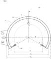
- FIG.7 A further inventive shutter arm in the form of a cut off disc is shown in Fig.7 .
- shutter arm 10" again has three positioning tenons with axes ⁇ 1-3 in a 0°, 90°, and 180° configuration.
- Bearing surface 12 in this case may comprise the whole or a part of the upper surface of the sickle 7 till its outer periphery D So , here comprising also the cut-off-line, when the thickness of the sickle, respectively bearing surface can be chosen big enough to provide stability and stiffness, which is easier for a paddle or disc-like sickle as shown with Fig.7 .
- a rim 13 can be provided also with such sickle types to ensure as mentioned mechanical properties.
- the inner periphery of the sickle D Si is only virtual here and, as an example, can be defined by an inner periphery touching the innermost position of two tenons 14 whereat a third tenon may be positioned away from the respective periphery, here in a further outward direction.
- each tenon can sit on the same or a different periphery with any embodiment of the invention, whereas positions near within, at the inner periphery or especially between the inner periphery and the rim are preferred due to ease and precision of positioning.
- Other positions of tenons and mortises may be chosen with any embodiment, with reference to different angular arrangements and/or different distances from the center for different tenons/mortises, up to the specific geometric needs within vacuum process chambers. And so can tenons and respective mortises of different geometry be combined with any of the shutter arm or disc embodiments as described in the examples.
Landscapes
- Physics & Mathematics (AREA)
- Engineering & Computer Science (AREA)
- Plasma & Fusion (AREA)
- Chemical & Material Sciences (AREA)
- Analytical Chemistry (AREA)
- Container, Conveyance, Adherence, Positioning, Of Wafer (AREA)
- Physical Vapour Deposition (AREA)
- Particle Accelerators (AREA)
- Magnetic Bearings And Hydrostatic Bearings (AREA)
Description
- The invention refers to a process shutter arrangement according to
claim 1, to a shutter disc according toclaim 9, to a shutter arm according toclaim 11, to a vacuum process system according toclaim 12, and to a method to use a process shutter arrangement according toclaim 14. - Process shutter arrangements comprising a shutter disc, also known as dummy disc as it replaces a wafer which is usually processed on the chuck, and a shutter arm to rotate the disc from a niche of the processing chamber or a separate compartment towards a pedestal or chuck, which carries the wafer or other substrates during processing, are widely used in vacuum equipment for semiconductor and optical industries, for instance for conditioning or pasting processes to extend the replacement cycle of the process shields, or simply to cover the top of a chuck to protect it against dust or mechanical exposure during servicing. As such equipment is expensive and highly automized, service intervals should be minimized, and precision and reliability of any step be optimized. Due to shorter process times and respective high number of process cycles, a higher number of conditioning and/or pasting operations per time unit follows.
- A dummy or shutter disc is a disc to replace a wafer in a processing position during a servicing, a conditioning, or a pasting step to protect the underlying equipment, especially the highly sensitive wafer bearing surface of the chuck. The disc should be able to receive a considerable amount of deposition material from the targets in case of target sputtering in the process chamber or allow a considerable amount of material to be removed when etching is performed during a so called conditioning or pasting step. When different sputter or conditioning/ pasting steps shall be performed, usually different discs will be used for sputtering or conditioning/pasting steps.
- A shutter sickle is the part of a shutter arm which carries the shutter disc and is provided at least with the positioning tenons. The sickle can essentially have the form of a sickle, however, can be also disc or paddle like itself and having slots to let the pins of the chuck pass during rotational movement to and from a center position over the chuck. Therefore, the inner periphery of the sickle DSi can define an actual periphery of the sickle or the innermost position of at least one of the tenons, which preferably sit in a position having essentially the same distance from the center of the sickle.
- In
US20020088771A1 a shutter disk having notched areas is disclosed to be used with a shutter arm assembly for fully automated handling. However additional installations like a modified cover-ring have to be provided and connected with the shielding to avoid mutual movement, which makes the installation laborious and might influence the placing precision due to thermal expansion of the shields. - To center the position of the shutter disk it is further known to apply a sensor on a shaft coupled to a robotic driven arm to detect the respective rotational position. To improve the respective sensing system, the same applicant as above discloses in
US7008517B1 a sputter disc which is centered by a central blind hole cooperating with an alignment post on a rotating blade. Therewith a relatively robust construction is necessary for the disc and the blade. At the same time the use of up to three different sensors is proposed to detect the disc in the housing. - Other prior art process shutter arrangements are known from
US2014271081 A1 andUS2012103793A1 . - Therefore, there is a need for light and dimensionally minimized components which can be moved faster and enable a high placing precision of the shutter disc, without the use of sophisticated multi-sensor systems.
- Surprisingly, it has been found that a respective process precision and high repeatability as well as minimized dimensions the components can be achieved by mere mechanical provisions of an inventive process shutter arrangement for a vacuum process system.
- It is therefore an objective of the present invention to provide a process shutter arrangement comprising:
- a shutter disc having an essentially circumferential outer diameter DDo, a thickness t, a first surface, and a second surface, the disc comprising at least three positioning mortises in the first surface near the outer diameter DDo, each mortise being centered with respect to a radially axis ξ1-3 in an xy-plane of the disc and having two long sides a positioned in parallel or right angled to axis ξ1-3, so that each of the axes ξ1-3 intersects at least one of the other axes in a center of the outer diameter DDo. As an example, the mortises may be arranged in a 120° position to each other or within a 180° section of the disc, e.g. at 0°, 90° and 180°, at the same or in a different radially distance from the center of the disc;
- a shutter arm comprising a bearing sickle with an inner periphery DSi, and at least three positioning tenons near or adjacent to the inner diameter DSi, and corresponding with positioning mortises to position the disc when set on the positioning tenons or on an optional bearing surface of the sickle. Thereby the disc may sit directly on the bearing surface or on top of the tenons, depending on the height of the tenons and respective depth of the mortises and the provision of a bearing surface.
- The bearing surface may extend radially from the inner periphery DSi of the sickle, e.g. in an outward direction and/or in a center direction. The tenons being positioned near or adjacent to the inner diameter DSi.
- The disc may further comprise a circumferential rim extending in a horizontally sidewise direction and/or in a vertically downward direction.
- The mortises can be arranged within an inner diameter DRi of the rim or within a projection of the inner positioning rim, and adjacent, e.g., immediately adjacent, to the rim or the projection. Mortises may have a basic rectangular geometry.
- Depending on the type of process to be performed when the disc protects the chuck, the material or the coating respectively plating of the disc can be chosen. If only a coating or plating of the disc is provided, at least the second side of the disc should be coated or plated and, if not protected by a clamp or holder on the chuck during the pasting or conditioning step, the second side of the rim, and the periphery of the disc respectively rim. For conditioning or servicing stainless steel or for a lightweight construction titanium or a ceramic material will work, whereby ceramic can be any densely sintered ceramic, e.g., aluminum oxide, silicon nitride or silicon carbide. If, however a pasting process should be performed, a respective pasting material like titanium or aluminum can be used as well as more exotic pasting materials like ZrFe or Pt.
- An inventive shutter arm may comprise a sidewall to enhance the stiffness of the sickle when space is limited. The sidewall may form at least in part an outer periphery DSo of the sickle, whereat the outer diameter DDo of the disc fits into the inner periphery DWi of the sidewall. The chuck dimension relates directly to the size of a wafer to be treated in a vacuum process which can be PVD, a CVD or an etch process as an example. With reference to the disc to chuck relation to be treated at the chuck, as an example for a disc having a flat first side as shown in
Fig.2 below, a very small or even no oversize will suffice. The same may apply for a disc with a rim having a vertical extension over the first surface as shown inFig.3 . However, to avoid any contact to the wafer bearing surface when sitting on the top of the chuck, a few millimeters may be added for the rim in a radially outwards direction of the the wafer bearing surface, whereas a few tenth of a millimeter for the vertical extension suffice to avoid touching of an all flat wafer bearing surface of a chuck by the disc. - The sidewall of the sickle may encompass the bearing surface in an angular range of about180° or smaller and can be a continuous or a interrupted sidewall, e.g. a sequence of pins. The bearing surface of the sickle may extend over an angular range of 180° - 360° and will be usually of 230 ± 30° of the inner diameter DSi.
- Tenons may have a basic rectangular, a circular or an oval geometry and have to be symmetrically with reference to a middle plane extending along an axes η1-3 and the height direction z of a tenon. When Tenons have a rectangular or square base, round corners or a circular end geometry will be usually provided.
- The disc may further comprise a flat and/or a notch at or in its outer diameter DDo, and the sickle may comprise a corresponding flat side and/or a nib, e.g., at the inner diameter DWi of the side wall. Such features may be provided when the chuck to be protected has respective positioning nibs or flat sides for the wafer to be processed.
- The shutter arm can be made of a material having an elastic modulus of at least 100 to 500 GPa to provide a high stiffness and avoid disturbing vibrations. Thereby densely sintered ceramic materials like aluminum oxide, silicon nitride, or silicon carbide are preferred due to their light weight.
- In an alternative embodiment the position of tenons and mortises can be reversed, which means that tenons can be provided at the first surface of the disc and mortises can be provided at the bearing surface of the sickle.
- It is a further objective of the present invention to provide a shutter disc having an essentially circumferential outer diameter DDo, a thickness t, a first surface, and a second surface, the disc comprising at least three positioning mortises in the first surface near the outer diameter DDo, each mortise being centered and symmetric with respect to a plane between a radially axis ξ1-3 in an xy-plane of the disc and the respective vertical, and having two long sides a positioned in parallel or right angled to axis ξ1-3. The mortises having further a short dimension b, and a depth dimension d, where b < a. It should be mentioned that neither positions of the mortises need to be regularly, nor need dimensions a1-3. b1-3, d1-3, be the same for a, b or d. However, some regularly positions, e.g., 0°, 90°, 180°, and/or identical dimensions a, b, d for mortises as well as identical dimensions for the respective dimensions m, n, h for the tenons can ease manufacture and/or handling of the disc respectively sickle.
- It is a further objective of the present invention to provide a shutter arm comprising a shaft with mounting means, a bearing sickle with an inner periphery DSi, and at least three positioning tenons near or adjacent to the inner diameter DSi, being in operative connection with positioning mortises to position the disc when set on the positioning tenons or on an optional bearing surface of the sickle. Thereby the disc may sit directly on the bearing surface or on top of the tenons, depending on the height of the tenons and respective depth of the mortises and the provision of a bearing surface.
- The bearing surface may extend radially from the inner periphery DSi of the sickle, e.g., in an outward direction and/or in a center direction. The tenons being positioned near or adjacent to the inner diameter DSi. The shutter arm further comprising a shaft with mounting means for the bearing sickle with a bearing surface radially extending from an inner periphery DSi of the sickle, and optionally a semi-circumferential side wall encompassing the bearing surface. Each tenant having an axis η1-3 positioned radially in an xy-plane of the sickle, and a long dimension m, a short dimension n, and a height dimension h, when n ≤ m. When n = m the tenon may have a circular or a square basis. Tenons are centered with reference to a plane comprising radially oriented axis η1-3 and a respective vertical.
- When the disc is mounted on the bearing surface of the sickle or on top of the tenons, tenons rest in respective mortises. Therefore, angular orientation and radial position of mortises and tenons has to be the same. As mentioned above mortises and tenons may be interchanged from the disc to the arm respectively vice-versa.
- Due to positioning means which may be provided on the chuck to position wafers having a notch or a flat respective positioning means like a flat and a flat side, a notch and a nib, can be foreseen with the disc which replaces the wafer for the servicing, conditioning or pasting step, and the sickle to bear the respective disk. As an example, flats and/or notches may be provided at or in the outer diameter DDo of the disc, whereat the flat side and/or the nib may be provided at the inner periphery DWi of the sidewall.
- It is a further objective of the present invention to provide a vacuum process system comprising a vacuum process chamber which houses a chuck with pins being movably mounted in a z-direction to a pin drive and a process shutter arrangement as discussed above and will be further discussed at the hand of the figures below. Thereby the arm of the process shutter arrangement is mounted to a vacuum side of a rod having a vertical rotational axis R, the rod being mounted to the chamber by a feedthrough, and being in operative connection with a shutter drive at the atmosphere side of the rod, to rotate the arm in a horizontal plane from a niche of the processing chamber or a separate compartment in a central position over the chuck, to enable that the pins of the chuck take over the disc.
- The pin drive of the chuck may be mounted to the process chamber, on atmosphere side or on the vacuum side. To lift the disc after the sickle has been rotated in a central position over the chuck, the drive may extend the pins in a uniform joint movement in an upper end position which can be between 5 and 30, e.g. 10 to 20 mm above the horizontal top of the chuck. Therefore, pins have to be provided within the inner diameter DSi of the sickle, when the latter is in the central position.
- The process system may further comprise a control unit connected to the pin drive and the shutter drive to coordinate rotational movement of the arm and linear z-movement of the pins to rotate the arm with the disc and lift and lower the disc when the arm is in the central position.
- The chuck of the process system can be a static chuck or a dynamic chuck which can be moved in a vertical direction from a loading position into a processing position and vice-versa.
- For a static chuck at least a handling cut-out in the process shields with a drivingly movable screen-shutter can be provided, when only a niche for the rest or idle position of the sickle is foreseen. Additionally, a disc handling opening can be provided with a respective lock in the chamber wall when a separate compartment should be foreseen. Disc handling cut-out and disc handling opening being mutually aligned and tailored to allow handling of a plate shaped disc. This can be in analogy to the substrate handling arrangement as disclosed in
WO 2017/215806 of the same applicant. Special reference is made toFig.1 and respective description. - Similar provisions can be made for a dynamic chuck as shown in
Fig.1 and respective description ofWO 2017/207144 A1 . Opening and closing of the handling cut-out in the process shields in this case can be performed by at least two telescopic cylindric shields encompassing the outer diameter of the chuck, whereat one of the shields is mounted to and moves with the chuck, whereby respective cut-outs are opened or closed by the respective other shield. - It is a further objective of the present invention to provide a method to use an inventive process shutter arrangement in a chamber of an inventive vacuum processing system as discussed above, whereat the method comprises the following steps:
- rotating the arrangement in a horizontal plane from the niche or the separate compartment in a central position over the chuck;
- extending the pins to lift the disc from the bearing surface in a horizontal plane above the shutter arm;
- rotating the empty arm back to the niche or the separate compartment;
- lowering and retracting the pins into the top surface of the chuck to cover the chuck with the disc;
- performing a conditioning, a pasting or a service operation in the process chamber.
- The Method may further comprise the following steps:
- extending the pins to lift the disc from the chuck in a plane above the shutter arm;
- rotating the empty arm from the niche or the separate compartment in the central position over the chuck and below the disc;
- lowering the pins to the bearing surface of the sickle whereat precision positioning takes place by entering of the tenons into the mortises;
- retracting the pins in a horizontal plan below the shutter arm;
- rotating the loaded arm back to the niche or the separate compartment;
- The invention shall now be further exemplified with the help of figures. Figures show the invention only in an exemplary way to outline the important features of the invention. The dimensions and geometrical relations of the different features as shown may differ from actual embodiments of the invention.
- The figures show:
- Fig.1:
- a process system comprising an inventive process shutter arrangement;
- Fig.2:
- an inventive shutter disc;
- Fig.3:
- an alternative inventive shutter disc;
- Fig.4:
- an inventive shutter arm;
- Fig.5:
- detail of an inventive shutter arm;
- Fig.6:
- an alternative inventive shutter arm;
- Fig.7:
- a further embodiment of an inventive shutter arm.
- The components and relevant functional principles of a process system operating in a conditioning or pasting mode are shown at the hand of
Fig.1 . Theexemplary process system 30 as shown has avacuum pump 32 attached to thevacuum chamber 31 which houses achuck 20 to process wafers or other flat substrates and an inventive process shutter arrangement consisting of ashutter disc 1 and ashutter arm 10. The shutter arm is mounted to therod 26 of ashutter drive 28 to rotate the shutter disc from aniche 34 of theprocessing chamber 31 or aseparate compartment 34 in a central position over the chuck. As usual the rod runs through avacuum feedthrough 27. When positioned over thechuck 20, pins 21 lift theshutter disc 1 in z-direction according to the double arrows from the bearingsurface 12 of thesickle 11. This is the very position which is shown inFig.1 withpins 21 in fully extended position. It should be noted that the pins need not be necessarily lifted above the sidewall as schematically shown. A lift of one or some few millimeters may suffice, as long as the sidewall does not encompass more than 180° of the bearing surface, which allows a rotation of the sickle into and out of central position without touching the lifted disc with its sidewall. Thepins 21 can be the pins as used to lift a wafer from a wafer blade. Thereafter thesickle 11 is rotated back into theniche 34 orseparate chamber 34 and pins are retracted in the chuck surface to position the disc on the chuck to protect its surface during a following conditioning, pasting process or servicing operation. The present shutter disc and shutter arm can be designed extremely flat, so that only a short lift is necessary to enable the back-rotation of the arm with the disc unloaded from thesickle 11. Thecontrol unit 31 can be used to trigger and control respective rotational movement of thearm 10 and vertical movement of thepins 21, which can be initiated by an operator for service or by the system control (not shown) to which thecontrol unit 31 may be integrated. The pin drive 22 which can be positioned on the atmosphere or the vacuum side of theprocess chamber 31, which also houses the pin transmission and further components (not shown) used for the operation of the chuck. - To load the
disc 1 again on thesickle 11, the process is reversed, pins 21 are extended to lift theshutter disc 1 from thechuck 20 and thesickle 11 is rotated in a central position so that the bearingsurface 12 is positioned between thechuck 20 and the lifteddisc 1. For long term process stability with series of some hundred process / pasting / conditioning cycles or more it is very important that positioning of the sickle and picking up of the disc from the chuck is performed with utmost precision. Therefore, light weight but highly rigid materials having a high modulus of elasticity, e.g., at least 100 to 500 GPa, should be used for the arm and sickle to avoid any disturbing material deformation due to change of temperature or load. In the present case aluminum oxide was used as material for the shutter arm with the sickle, however other materials of similar properties, e.g., as shown above may be used too. Theshutter drive motor 28 is coupled to therod 26 and an encoder to ensure high position accuracy. - However most importantly the picking up of the disc by the sickle of the arm is supported by respective positioning features on the disc and sickle. So, when the disc is lowered by retraction of the pins towards the sickle and pins 21 are further retracted in a position at least below the bearing
surface 12, precision positioning is completed by threepositioning tenons 14 in thesickle surface 12 which enter into therespective mortises 4 in thelower disc surface 2, whereby the position of thedisc 1 is perfectly defined on the bearingsurface 12 of thesickle 11 before it is rotated back in rest position. Therewith for the next conditioning or pasting operation the shutter drive can rotate the arm with the disc in position above the chuck and handover the disc to the pins at the very right place without further measures. - It should be mentioned that especially the shown thickness dimensions of arm and sickle, and disk, as well as dimensions of the precision positioning features are oversized in the figures to better show the functionality.
- It is further evident that vacuum process systems as shown in
Fig.1 usually will have additional features like gas inlets for PVD or CVD processes, sputtering targets to deposit materials, etching devices or the like to process a wafer or other flat substrates, which only makes conditioning, pasting or service cycles necessary. However, as the present invention focuses on the improvement of a process sputter arrangement, only respective relevant installations are discussed and shown in the figures. - A
shutter disc 1 with threepositioning mortises 4 in afirst surface 2 and arim 6 optionally provided with a flat 8 and/or anotch 9 is shown inFig.2 . The shutter disc having a thickness t, the mortises having a length a, a width b, and a depth d (see alsoFig.3 ) and being positioned with their longitudinal axes ξ1-3 radially in a peripheral position at 0°, 90° and 180° of the disc perimeter. The disc also comprises threenicks 5 in asecond surface 3 of thedisc 1, positioned on an inner extension of the projection of axes ξ1-3, adjacent to mortises 4. These nicks can be used for a first placing step, e.g. during a first manual placing of the disc. Similarly nicks and/or bevels can be used with any other embodiment of a shutter disc. Mortises can have a circumferential bevel 4' and tenons can have a circumferential chamfer 14', each alone or in cooperation with each other to ease matching of the two positioning elements.Mortises 4 can be positioned on axis ξ1-3 in parallel and symmetric to it as indicated in solid lines, or alternatively right angled to axis ξ1-3 as indicated in dashed lines andreference number 4", which will usually be also symmetric as referred to before. - In
Fig.3 asimilar shutter disc 1 with threepositioning mortises 4 in thefirst surface 2 and arim 6 here provided with a flat 8 is shown. In the case of the disk inFig.3 therim 6 also has a vertical extension which slightly towers over thefirst surface 2 and thereby may encompass the wafer bearing surface of thechuck 20 and sit on a peripheral chuck surface. - Despite of the fact, that the disks as shown in
Fig.2 andFig.3 can be designed very flat with a thickness t from 2 to 20 mm, or 3 to 10 mm, the provision of arim 6 of lower thickness tR, which should refer to the thickness of a wafer to be processed, can make it easy to clamp the disc on the chuck with usual wafer clamps, e.g. during sputtering processes. As far as provided, therim 6 can be small but at the same time wide enough to provide place for the positioning flat 8 ornotch 9. As an example, disc dimensions for a 300 mm chuck, which are usual chuck dimensions to process 300 mm wafers, can be:
- A
shutter disk arm 10 which can be mounted to therod 26 of a rotation unit by ashaft 15 with flange andpositioning slots 16 to level the sickle is shown inFig.4 . Alternatively, or in addition a central mounting on the shaft, as shown inFig.1 , can be foreseen. - The
arm 10 further comprises asickle 11 with a bearingsurface 12 andsidewall 13. Threepositioning tenants 14, each offset by 90° from the next tenant, are placed on the bearingsurface 11 next to the inner diameter of the sickle, with their axes η1-3 arranged radially towards the inner periphery of the sickle DSi. Therewith, when thedisc 1 is positioned on the sickle 11 axes ξ1-3 ofmortises 4 and axes η1-3 of thetenants 14 coincide and the inner periphery DWi of thesidewall 13 encompasses the outer diameter DDo of thedisc 1 on the bearingsurface 12. To ensure highest positioning precision the small dimension b of themortise 4 and the respective dimension n of thetenant 14 should be very similarly sized so that, as an example in the case of an arrangement for a 300 mm wafer, the difference should be about b - n = 0.1 ± 0.05 mm. In contrast to that the long dimension a of themortise 4 should be provided considerably longer than the respective dimension m of thetenant 14 to enable thermal compensation. As an example, again for a 300 mm wafer arrangement, when using a metal disc and a ceramic sickle, the difference should be at least 1 to 3 mm, depending on the maximal thermal load during processing. When nibs or flat sides are used to position the wafer on the chuck, a flat side 8' and/or a nib 9' can be foreseen as shown in dashed lines.Reference number 17 refers to an optional out-cut to allow an optical sensor (not shown), to acknowledge correct positioning of the disc. The optical sensor can be mounted in a niche or a separate rest chamber for the arm and disc or can be integrated on thearm 10. One ormore openings 18 as shown in dotted lines may be provided in the bearingsurface 11 and a lower part of theside wall 13 to allow protrusions from the chuck or pins positioned further outward on the chuck to pass. Width w of the bearing surface should be from at least about 1.5 the length m of a tenon till about 30 mm to allowpins 21 to pass inside when lifting thedisc 1. - The magnifying glass in the upper part of the drawing shows on the left side a view from the center of the
sickle 11 towards atenant 14 on the bearingsurface 12 and a sideview in a 90° perspective to the left side. - Tenants may have a maximal length dimension m, a maximal width dimension n, and a height h whereby:


- Therewith mortises having a maximal length dimension a and a maximal width dimension b, can be used with the following dimensions:


-
Fig.5 shows further details of apositioning tenant 14 in top view. Thetenant 14 comprising two circular edge sections of radius r, a straight middle part here of length l, and an upper finish with a circumferential chamfer 14'. As an example, r can be 2 mm and height h of the tenant can be also 2 mm. Thereby minimized dimensions and good positioning properties can be achieved. A variation of the length l of the straight middle part can be from about 0 to 4r or more, which may depend of the width w = (DWi - DSi) / 2 of the bearingsurface 12. Alternatively, round tenants, tenants with an oval base or other convenient base forms as known to the man skilled in the art can be used. - A further embodiment of an inventive shutter arm is shown in
Fig.6 . Contrary to the forgoing arm embodiment in this casecircular tenons 14, mounted on an inner end ofcantilevers 19, are used to position and hold the respective disc, which means the disc sits on the tenons only. The cantilevers project radially from theside wall 13 towards the center of thesickle 7. To hold the disc save in balance, the tenons are placed in a 120° position from each other at a mere virtual inner periphery of the sickle DSi, so that there is no further need of the bearingsurface 12 as shown inFig.4 orFig.7 . Axes η1-3 cut each other in the center point of the sickle. Such a shutter arm can be combined with any of the previous disc embodiments when the mortises are arranged in a respective 120° position. - A further inventive shutter arm in the form of a cut off disc is shown in
Fig.7 . With thisembodiment shutter arm 10" again has three positioning tenons with axes η1-3 in a 0°, 90°, and 180° configuration. Bearingsurface 12 in this case may comprise the whole or a part of the upper surface of thesickle 7 till its outer periphery DSo, here comprising also the cut-off-line, when the thickness of the sickle, respectively bearing surface can be chosen big enough to provide stability and stiffness, which is easier for a paddle or disc-like sickle as shown withFig.7 . Otherwise, arim 13 can be provided also with such sickle types to ensure as mentioned mechanical properties. To allowpins 21 of thechuck 20 to stay in their extended end position after they have taken over thedisc 1 from the shutter disc arrangement, and the arm with the sickle has to rotate back in its rest position, threeopenings 18 are provided which allow the arm to rotate without touching thepins 21. Once again, the inner periphery of the sickle DSi is only virtual here and, as an example, can be defined by an inner periphery touching the innermost position of twotenons 14 whereat a third tenon may be positioned away from the respective periphery, here in a further outward direction. In principle however, each tenon can sit on the same or a different periphery with any embodiment of the invention, whereas positions near within, at the inner periphery or especially between the inner periphery and the rim are preferred due to ease and precision of positioning. Other positions of tenons and mortises may be chosen with any embodiment, with reference to different angular arrangements and/or different distances from the center for different tenons/mortises, up to the specific geometric needs within vacuum process chambers. And so can tenons and respective mortises of different geometry be combined with any of the shutter arm or disc embodiments as described in the examples. -
- I
- SHUTTER DISC
- 1
- disc
- 2
- first surface
- 3
- second surface
- 4
- positioning mortise in parallel to axis ξ1-3
- 4'
- bevel
- 4"
- alternative mortise, right angled to axis ξ1-3
- 5
- control nick (second surface)
- 6, 6'
- rim
- 7
- recess
- 8
- flat
- 9
- notch
- a, b, d
- long, short side, depth of a mortise
- DDo
- outer diameter of the disc
- DRi
- inner diameter of the rim
- t
- thickness disc
- tR
- thickness rim
- ξ1-3
- longitudinal axis of a notch
- II
- PROCESS SHUTTER ARM
- 8'
- flat side
- 9'
- nib
- 10,10',10"
- arm
- 11
- bearing sickle
- 12
- bearing surface
- 13
- side wall
- 14
- positioning tenon
- 14'
- chamfer
- 15
- shaft
- 15'
- flange
- 16
- positioning slot
- 17
- out-cut for sensor
- 18
- opening
- 19
- cantilever
- DSi
- inner periphery of the sickle
- DWi
- inner periphery of the side wall
- DSo
- outer periphery of the sickle
- m, n, h
- long, short side, height of a tenon
- w
- width of the bearing surface
- η1-3
- longitudinal axis of a tenant
- III
- CHUCK
- 20
- chuck
- 21
- pin
- 22
- pin drive
- 23
- chuck surface
- 24
- chuck base
- IV
- ROTATION UNIT
- 26
- shutter rod
- 27
- rod feedthrough
- 28
- shutter drive (motor, encoder, gear)
- R
- vertical axis of the rod
- V
- PROCESS SYSTEM
- 30
- process system
- 31
- vacuum process chamber
- 32
- control unit
- 33
- vacuum pump
- 34
- niche or separate chamber
Claims (15)
- A process shutter arrangement for a vacuum process system comprising:- a shutter disc (1) having an essentially circumferential outer diameter DDo, a thickness t, a first surface (2), and a second surface (3), the disc comprising at least three positioning mortises (4) in the first surface (2) near the outer diameter DDo, each mortise being centered with respect to a radially axis ξ1-3 in an xy-plane of the disc and having two long sides a positioned in parallel or right angled to the respective axis ξ1-3;- a shutter arm (10) comprising a bearing sickle (11) with an inner periphery DSi, and at least three positioning tenons near or adjacent to the inner diameter DSi, and corresponding with positioning mortises (4) to position the disc when set on the positioning tenons or on an optional bearing surface of the sickle.
- The arrangement according to claim 1, wherein the bearing surface (12) extends radially from the inner periphery DSi of the sickle, the tenons being positioned near or adjacent to the inner diameter DSi.
- The arrangement according to claim 1 or 2, wherein the disc further comprises a circumferential rim (6, 6') extending in a horizontally sidewise direction and/or in a vertically downward direction, wherein the mortises are arranged optionally within an inner diameter DRi of the rim or within a projection of the inner positioning rim, and adjacent to the rim or the projection.
- The arrangement according to one of the forgoing claims, wherein the mortises have a basic rectangular geometry, and/or the disc is coated with or made of a metal or a ceramic material.
- The arrangement according to one of the forgoing claims, wherein the shutter arm comprises a sidewall forming at least in part an outer periphery DSo of the sickle, whereat the outer diameter DDo of the disc fits into the inner periphery DWi of the sidewall, wherein optionally the sidewall encompasses about semi-circularly the bearing surface, or the tenons are mounted on cantilevers projecting from the side wall.
- The arrangement according to one of the forgoing claims, wherein the bearing surface of the sickle extends over an angular range of 180 - 360° of the inner diameter DSi of the sickle.
- The arrangement according to one of the forgoing claims, wherein the tenons have a basic rectangular, a circular, or an oval geometry, wherein preferably the tenons have a rectangular or square base with round corners or a circular end geometry.
- The arrangement according to one of the forgoing claims, wherein the arm is made of a material having a modulus of elasticity which is at least 100 GPa, especially a respective ceramic material, and/or the tenons are provided at the first surface of the disc and the mortises are provided at the bearing surface of the sickle or on cantilevers projecting from the side wall.
- A shutter disc having an essentially circumferential outer diameter DDo, a thickness t, a first surface (2), and a second surface (3), the disc comprising at least three positioning mortises (4) in the first surface (2) near the outer diameter DDo, each mortise being centered and symmetric with respect to a plane between a radially axis ξ1-3 in an xy-plane of the disc and the respective vertical, and having two long sides a positioned in parallel or right angled to axis ξ1-3, and a short dimension b, and a depth dimension d, where b < a.
- A shutter disc according to claim 9, wherein the second surface comprises at least one control nick.
- A shutter arm (10) comprising a shaft (15) with mounting means, a bearing sickle (11) with an inner periphery DSi, and at least three positioning tenons near or adjacent to an inner diameter DSi of the sickle each tenant being positioned on a radially axis η1-3 in an xy-plane of the sickle and symmetrically with reference to a middle plane extending along the respective axes η1-3 and the height direction z, each tenon having a long dimension m, a short dimension n, and a height dimension h, where n ≤ m.
- A vacuum process system comprising a vacuum process chamber (31) housing a chuck with pins (21) being movably mounted in a z-direction to a pin drive (22) and a process shutter arrangement according to one of claims 1 to 8, whereat the arm 10 of the arrangement is mounted to a vacuum side of a rod having a vertical rotational axis R, being mounted to the chamber by a feedthrough, and being in operative connection with a shutter drive at the atmosphere side of the rod, to rotate the arm from a niche of the processing chamber or a separate compartment in a central position over the chuck, whereat preferably the pin drive is mounted to the process chamber on atmosphere or on the vacuum side.
- The process system according to claim 12 further comprising a control unit connected to the pin drive and the shutter drive to coordinate rotational movement of the arm and linear z-movement of the pins to rotate the arm with the disc and lift and lower the disc when the arm is in the central position.
- Method to use a process shutter arrangement according to one of claims 1 to 8 in a chamber of a vacuum process system according to claim 12 or 13 comprising the following steps:- rotating the arrangement in a horizontal plane from the niche or the separate compartment in a central position over the chuck;- extending the pins to lift the disc from the bearing surface in a horizontal plane above the arm;- rotating the empty arm back to the niche or the separate compartment;- lowering and retracting the pins into the top surface of the chuck to cover the chuck with the disc;- performing a conditioning, a pasting or a service operation in the process chamber.
- Method according to claim 14 further comprising the following steps:- extending the pins to lift the disc from the chuck in a plane above the arm;- rotating the empty arm from the niche or the separate compartment in the central position over the chuck and below the disc;- lowering the pins to the bearing surface of the sickle whereat precision positioning takes place by entering of the tenons into the mortises;- retracting the pins in a horizontal plane below the arm;- rotating the loaded arm back to the niche or the separate compartment.
Applications Claiming Priority (2)
| Application Number | Priority Date | Filing Date | Title |
|---|---|---|---|
| CH0701062021 | 2021-07-27 | ||
| PCT/EP2022/069134 WO2023006387A1 (en) | 2021-07-27 | 2022-07-08 | Process shutter arrangement |
Publications (2)
| Publication Number | Publication Date |
|---|---|
| EP4377992A1 EP4377992A1 (en) | 2024-06-05 |
| EP4377992B1 true EP4377992B1 (en) | 2025-06-18 |
Family
ID=82780921
Family Applications (1)
| Application Number | Title | Priority Date | Filing Date |
|---|---|---|---|
| EP22750674.8A Active EP4377992B1 (en) | 2021-07-27 | 2022-07-08 | Process shutter arrangement |
Country Status (7)
| Country | Link |
|---|---|
| US (1) | US20240347326A1 (en) |
| EP (1) | EP4377992B1 (en) |
| JP (1) | JP2024528013A (en) |
| KR (1) | KR20240039175A (en) |
| CN (1) | CN117716484A (en) |
| TW (1) | TW202314949A (en) |
| WO (1) | WO2023006387A1 (en) |
Family Cites Families (9)
| Publication number | Priority date | Publication date | Assignee | Title |
|---|---|---|---|---|
| JP3233496B2 (en) * | 1993-04-14 | 2001-11-26 | 株式会社アルバック | Vacuum deposition equipment |
| US7008517B2 (en) | 2002-02-20 | 2006-03-07 | Applied Materials, Inc. | Shutter disk and blade for physical vapor deposition chamber |
| TWI431668B (en) * | 2009-06-24 | 2014-03-21 | Ulvac Inc | Vacuum deposition apparatus and method of detecting position of shutter board in vacuum deposition apparatus |
| GB2476476B (en) * | 2009-12-23 | 2013-05-22 | Nanobeam Ltd | Charged particle beam system |
| JP2013057108A (en) * | 2011-09-09 | 2013-03-28 | Ulvac Japan Ltd | Multiple sputtering apparatus |
| US9564348B2 (en) * | 2013-03-15 | 2017-02-07 | Applied Materials, Inc. | Shutter blade and robot blade with CTE compensation |
| WO2017207144A1 (en) | 2016-06-03 | 2017-12-07 | Evatec Ag | Plasma etch chamber and method of plasma etching |
| JP6991164B2 (en) | 2016-06-15 | 2022-01-12 | エヴァテック・アーゲー | Method for manufacturing vacuum-treated chamber and vacuum-treated plate-shaped substrate |
| KR102500219B1 (en) * | 2018-05-12 | 2023-02-14 | 어플라이드 머티어리얼스, 인코포레이티드 | Pre-clean chamber with integrated shutter garage |
-
2022
- 2022-07-06 TW TW111125321A patent/TW202314949A/en unknown
- 2022-07-08 CN CN202280052299.8A patent/CN117716484A/en active Pending
- 2022-07-08 EP EP22750674.8A patent/EP4377992B1/en active Active
- 2022-07-08 US US18/292,596 patent/US20240347326A1/en active Pending
- 2022-07-08 WO PCT/EP2022/069134 patent/WO2023006387A1/en not_active Ceased
- 2022-07-08 KR KR1020247006724A patent/KR20240039175A/en active Pending
- 2022-07-08 JP JP2024505143A patent/JP2024528013A/en active Pending
Also Published As
| Publication number | Publication date |
|---|---|
| CN117716484A (en) | 2024-03-15 |
| TW202314949A (en) | 2023-04-01 |
| WO2023006387A1 (en) | 2023-02-02 |
| KR20240039175A (en) | 2024-03-26 |
| US20240347326A1 (en) | 2024-10-17 |
| JP2024528013A (en) | 2024-07-26 |
| EP4377992A1 (en) | 2024-06-05 |
Similar Documents
| Publication | Publication Date | Title |
|---|---|---|
| US11587821B2 (en) | Substrate lift mechanism and reactor including same | |
| CN113906546B (en) | Wafer placement correction in an indexed multi-station processing chamber | |
| CN100499060C (en) | Wafer positioning method and apparatus, processing system, and method for positioning wafer seat rotating axis of wafer positioning apparatus | |
| TWI739470B (en) | Front opening ring pod | |
| JP4580498B2 (en) | Method and apparatus for aligning cassettes | |
| CN113795608B (en) | Pedestal Lift for Semiconductor Processing Chambers | |
| US6677166B2 (en) | Method for confirming alignment of a substrate support mechanism in a semiconductor processing system | |
| TW200527172A (en) | Auto-diagnostic method and apparatus | |
| KR20010071819A (en) | Wafer carrier and method for handling of wafers with minimal contact | |
| US8491252B2 (en) | Transport method for disk-shaped workpieces | |
| US20050111944A1 (en) | Compact wafer handling system with single axis robotic arm and prealigner-cassette elevator | |
| US20240347326A1 (en) | Process shutter arrangement | |
| EP1635988A2 (en) | Integrated tool with interchangeable wet processing components for processing microfeature workpieces and automated calibration systems | |
| EP1866958B1 (en) | High speed substrate aligner apparatus | |
| US20240213060A1 (en) | Apparatuses for measuring gap between a substrate support plane and gas distribution device | |
| US7493231B2 (en) | Process for determining the actual position of a rotation axis of a transportation mechanism | |
| CN210287480U (en) | High-flux discrete mask device | |
| US20030154002A1 (en) | Method and apparatus for aligning a cassette handler | |
| US7717661B1 (en) | Compact multiple diameters wafer handling system with on-chuck wafer calibration and integrated cassette-chuck transfer | |
| CN105097606A (en) | Shielding disc and reaction chamber | |
| US8968532B2 (en) | Electrochemical processor alignment system | |
| EP4535410A1 (en) | Pin-lifter with positioning compensation | |
| CN112342494B (en) | A high-throughput discrete mask device | |
| CN120709199A (en) | Coaxiality tester, test system and coaxiality test method |
Legal Events
| Date | Code | Title | Description |
|---|---|---|---|
| STAA | Information on the status of an ep patent application or granted ep patent |
Free format text: STATUS: UNKNOWN |
|
| STAA | Information on the status of an ep patent application or granted ep patent |
Free format text: STATUS: THE INTERNATIONAL PUBLICATION HAS BEEN MADE |
|
| PUAI | Public reference made under article 153(3) epc to a published international application that has entered the european phase |
Free format text: ORIGINAL CODE: 0009012 |
|
| STAA | Information on the status of an ep patent application or granted ep patent |
Free format text: STATUS: REQUEST FOR EXAMINATION WAS MADE |
|
| 17P | Request for examination filed |
Effective date: 20240117 |
|
| AK | Designated contracting states |
Kind code of ref document: A1 Designated state(s): AL AT BE BG CH CY CZ DE DK EE ES FI FR GB GR HR HU IE IS IT LI LT LU LV MC MK MT NL NO PL PT RO RS SE SI SK SM TR |
|
| GRAP | Despatch of communication of intention to grant a patent |
Free format text: ORIGINAL CODE: EPIDOSNIGR1 |
|
| STAA | Information on the status of an ep patent application or granted ep patent |
Free format text: STATUS: GRANT OF PATENT IS INTENDED |
|
| DAV | Request for validation of the european patent (deleted) | ||
| DAX | Request for extension of the european patent (deleted) | ||
| INTG | Intention to grant announced |
Effective date: 20241017 |
|
| P01 | Opt-out of the competence of the unified patent court (upc) registered |
Free format text: CASE NUMBER: APP_61008/2024 Effective date: 20241113 |
|
| P02 | Opt-out of the competence of the unified patent court (upc) changed |
Free format text: CASE NUMBER: APP_61047/2024 Effective date: 20241114 |
|
| GRAJ | Information related to disapproval of communication of intention to grant by the applicant or resumption of examination proceedings by the epo deleted |
Free format text: ORIGINAL CODE: EPIDOSDIGR1 |
|
| STAA | Information on the status of an ep patent application or granted ep patent |
Free format text: STATUS: REQUEST FOR EXAMINATION WAS MADE |
|
| GRAP | Despatch of communication of intention to grant a patent |
Free format text: ORIGINAL CODE: EPIDOSNIGR1 |
|
| STAA | Information on the status of an ep patent application or granted ep patent |
Free format text: STATUS: GRANT OF PATENT IS INTENDED |
|
| INTC | Intention to grant announced (deleted) | ||
| GRAJ | Information related to disapproval of communication of intention to grant by the applicant or resumption of examination proceedings by the epo deleted |
Free format text: ORIGINAL CODE: EPIDOSDIGR1 |
|
| STAA | Information on the status of an ep patent application or granted ep patent |
Free format text: STATUS: REQUEST FOR EXAMINATION WAS MADE |
|
| INTG | Intention to grant announced |
Effective date: 20250307 |
|
| GRAP | Despatch of communication of intention to grant a patent |
Free format text: ORIGINAL CODE: EPIDOSNIGR1 |
|
| STAA | Information on the status of an ep patent application or granted ep patent |
Free format text: STATUS: GRANT OF PATENT IS INTENDED |
|
| GRAS | Grant fee paid |
Free format text: ORIGINAL CODE: EPIDOSNIGR3 |
|
| INTG | Intention to grant announced |
Effective date: 20250415 |
|
| GRAA | (expected) grant |
Free format text: ORIGINAL CODE: 0009210 |
|
| STAA | Information on the status of an ep patent application or granted ep patent |
Free format text: STATUS: THE PATENT HAS BEEN GRANTED |
|
| AK | Designated contracting states |
Kind code of ref document: B1 Designated state(s): AL AT BE BG CH CY CZ DE DK EE ES FI FR GB GR HR HU IE IS IT LI LT LU LV MC MK MT NL NO PL PT RO RS SE SI SK SM TR |
|
| REG | Reference to a national code |
Ref country code: GB Ref legal event code: FG4D |
|
| REG | Reference to a national code |
Ref country code: CH Ref legal event code: EP |
|
| REG | Reference to a national code |
Ref country code: DE Ref legal event code: R096 Ref document number: 602022016150 Country of ref document: DE |
|
| REG | Reference to a national code |
Ref country code: CH Ref legal event code: EP |
|
| REG | Reference to a national code |
Ref country code: IE Ref legal event code: FG4D |
|
| PG25 | Lapsed in a contracting state [announced via postgrant information from national office to epo] |
Ref country code: FI Free format text: LAPSE BECAUSE OF FAILURE TO SUBMIT A TRANSLATION OF THE DESCRIPTION OR TO PAY THE FEE WITHIN THE PRESCRIBED TIME-LIMIT Effective date: 20250618 |
|
| PGFP | Annual fee paid to national office [announced via postgrant information from national office to epo] |
Ref country code: DE Payment date: 20250901 Year of fee payment: 4 |
|
| REG | Reference to a national code |
Ref country code: LT Ref legal event code: MG9D |
|
| PG25 | Lapsed in a contracting state [announced via postgrant information from national office to epo] |
Ref country code: GR Free format text: LAPSE BECAUSE OF FAILURE TO SUBMIT A TRANSLATION OF THE DESCRIPTION OR TO PAY THE FEE WITHIN THE PRESCRIBED TIME-LIMIT Effective date: 20250919 Ref country code: NO Free format text: LAPSE BECAUSE OF FAILURE TO SUBMIT A TRANSLATION OF THE DESCRIPTION OR TO PAY THE FEE WITHIN THE PRESCRIBED TIME-LIMIT Effective date: 20250918 |
|
| PG25 | Lapsed in a contracting state [announced via postgrant information from national office to epo] |
Ref country code: BG Free format text: LAPSE BECAUSE OF FAILURE TO SUBMIT A TRANSLATION OF THE DESCRIPTION OR TO PAY THE FEE WITHIN THE PRESCRIBED TIME-LIMIT Effective date: 20250618 |
|
| PG25 | Lapsed in a contracting state [announced via postgrant information from national office to epo] |
Ref country code: HR Free format text: LAPSE BECAUSE OF FAILURE TO SUBMIT A TRANSLATION OF THE DESCRIPTION OR TO PAY THE FEE WITHIN THE PRESCRIBED TIME-LIMIT Effective date: 20250618 |
|
| PGFP | Annual fee paid to national office [announced via postgrant information from national office to epo] |
Ref country code: AT Payment date: 20251020 Year of fee payment: 4 |
|
| PG25 | Lapsed in a contracting state [announced via postgrant information from national office to epo] |
Ref country code: RS Free format text: LAPSE BECAUSE OF FAILURE TO SUBMIT A TRANSLATION OF THE DESCRIPTION OR TO PAY THE FEE WITHIN THE PRESCRIBED TIME-LIMIT Effective date: 20250918 |
|
| REG | Reference to a national code |
Ref country code: NL Ref legal event code: MP Effective date: 20250618 |
|
| PG25 | Lapsed in a contracting state [announced via postgrant information from national office to epo] |
Ref country code: LV Free format text: LAPSE BECAUSE OF FAILURE TO SUBMIT A TRANSLATION OF THE DESCRIPTION OR TO PAY THE FEE WITHIN THE PRESCRIBED TIME-LIMIT Effective date: 20250618 |
|
| PG25 | Lapsed in a contracting state [announced via postgrant information from national office to epo] |
Ref country code: NL Free format text: LAPSE BECAUSE OF FAILURE TO SUBMIT A TRANSLATION OF THE DESCRIPTION OR TO PAY THE FEE WITHIN THE PRESCRIBED TIME-LIMIT Effective date: 20250618 |
|
| REG | Reference to a national code |
Ref country code: DE Ref legal event code: R079 Ref document number: 602022016150 Country of ref document: DE Free format text: PREVIOUS MAIN CLASS: H01L0021677000 Ipc: H10P0072300000 |
|
| PG25 | Lapsed in a contracting state [announced via postgrant information from national office to epo] |
Ref country code: PT Free format text: LAPSE BECAUSE OF FAILURE TO SUBMIT A TRANSLATION OF THE DESCRIPTION OR TO PAY THE FEE WITHIN THE PRESCRIBED TIME-LIMIT Effective date: 20251020 |
|
| REG | Reference to a national code |
Ref country code: AT Ref legal event code: MK05 Ref document number: 1805036 Country of ref document: AT Kind code of ref document: T Effective date: 20250618 |
|
| PG25 | Lapsed in a contracting state [announced via postgrant information from national office to epo] |
Ref country code: IS Free format text: LAPSE BECAUSE OF FAILURE TO SUBMIT A TRANSLATION OF THE DESCRIPTION OR TO PAY THE FEE WITHIN THE PRESCRIBED TIME-LIMIT Effective date: 20251018 |
|
| PG25 | Lapsed in a contracting state [announced via postgrant information from national office to epo] |
Ref country code: AT Free format text: LAPSE BECAUSE OF FAILURE TO SUBMIT A TRANSLATION OF THE DESCRIPTION OR TO PAY THE FEE WITHIN THE PRESCRIBED TIME-LIMIT Effective date: 20250618 Ref country code: SM Free format text: LAPSE BECAUSE OF FAILURE TO SUBMIT A TRANSLATION OF THE DESCRIPTION OR TO PAY THE FEE WITHIN THE PRESCRIBED TIME-LIMIT Effective date: 20250618 |
|
| PG25 | Lapsed in a contracting state [announced via postgrant information from national office to epo] |
Ref country code: CZ Free format text: LAPSE BECAUSE OF FAILURE TO SUBMIT A TRANSLATION OF THE DESCRIPTION OR TO PAY THE FEE WITHIN THE PRESCRIBED TIME-LIMIT Effective date: 20250618 |
|
| PG25 | Lapsed in a contracting state [announced via postgrant information from national office to epo] |
Ref country code: PL Free format text: LAPSE BECAUSE OF FAILURE TO SUBMIT A TRANSLATION OF THE DESCRIPTION OR TO PAY THE FEE WITHIN THE PRESCRIBED TIME-LIMIT Effective date: 20250618 |
|
| PG25 | Lapsed in a contracting state [announced via postgrant information from national office to epo] |
Ref country code: EE Free format text: LAPSE BECAUSE OF FAILURE TO SUBMIT A TRANSLATION OF THE DESCRIPTION OR TO PAY THE FEE WITHIN THE PRESCRIBED TIME-LIMIT Effective date: 20250618 |
|
| PG25 | Lapsed in a contracting state [announced via postgrant information from national office to epo] |
Ref country code: SK Free format text: LAPSE BECAUSE OF FAILURE TO SUBMIT A TRANSLATION OF THE DESCRIPTION OR TO PAY THE FEE WITHIN THE PRESCRIBED TIME-LIMIT Effective date: 20250618 |
|
| PG25 | Lapsed in a contracting state [announced via postgrant information from national office to epo] |
Ref country code: ES Free format text: LAPSE BECAUSE OF FAILURE TO SUBMIT A TRANSLATION OF THE DESCRIPTION OR TO PAY THE FEE WITHIN THE PRESCRIBED TIME-LIMIT Effective date: 20250618 |
|
| REG | Reference to a national code |
Ref country code: CH Ref legal event code: H13 Free format text: ST27 STATUS EVENT CODE: U-0-0-H10-H13 (AS PROVIDED BY THE NATIONAL OFFICE) Effective date: 20260224 |
|
| PG25 | Lapsed in a contracting state [announced via postgrant information from national office to epo] |
Ref country code: RO Free format text: LAPSE BECAUSE OF FAILURE TO SUBMIT A TRANSLATION OF THE DESCRIPTION OR TO PAY THE FEE WITHIN THE PRESCRIBED TIME-LIMIT Effective date: 20250618 Ref country code: LU Free format text: LAPSE BECAUSE OF NON-PAYMENT OF DUE FEES Effective date: 20250708 |
|
| REG | Reference to a national code |
Ref country code: DE Ref legal event code: R097 Ref document number: 602022016150 Country of ref document: DE |
|
| REG | Reference to a national code |
Ref country code: BE Ref legal event code: MM Effective date: 20250731 |
|
| PG25 | Lapsed in a contracting state [announced via postgrant information from national office to epo] |
Ref country code: MC Free format text: LAPSE BECAUSE OF FAILURE TO SUBMIT A TRANSLATION OF THE DESCRIPTION OR TO PAY THE FEE WITHIN THE PRESCRIBED TIME-LIMIT Effective date: 20250618 |
|
| PG25 | Lapsed in a contracting state [announced via postgrant information from national office to epo] |
Ref country code: DK Free format text: LAPSE BECAUSE OF FAILURE TO SUBMIT A TRANSLATION OF THE DESCRIPTION OR TO PAY THE FEE WITHIN THE PRESCRIBED TIME-LIMIT Effective date: 20250618 |
|
| PG25 | Lapsed in a contracting state [announced via postgrant information from national office to epo] |
Ref country code: BE Free format text: LAPSE BECAUSE OF NON-PAYMENT OF DUE FEES Effective date: 20250731 Ref country code: IT Free format text: LAPSE BECAUSE OF FAILURE TO SUBMIT A TRANSLATION OF THE DESCRIPTION OR TO PAY THE FEE WITHIN THE PRESCRIBED TIME-LIMIT Effective date: 20250618 |
|
| PG25 | Lapsed in a contracting state [announced via postgrant information from national office to epo] |
Ref country code: CH Free format text: LAPSE BECAUSE OF NON-PAYMENT OF DUE FEES Effective date: 20250731 |
|
| PLBE | No opposition filed within time limit |
Free format text: ORIGINAL CODE: 0009261 |
|
| STAA | Information on the status of an ep patent application or granted ep patent |
Free format text: STATUS: NO OPPOSITION FILED WITHIN TIME LIMIT |
|
| REG | Reference to a national code |
Ref country code: CH Ref legal event code: L10 Free format text: ST27 STATUS EVENT CODE: U-0-0-L10-L00 (AS PROVIDED BY THE NATIONAL OFFICE) Effective date: 20260430 |