EP4376028A1 - Cable having cooling function, current transmission device, and electric vehicle - Google Patents
Cable having cooling function, current transmission device, and electric vehicle Download PDFInfo
- Publication number
- EP4376028A1 EP4376028A1 EP22845269.4A EP22845269A EP4376028A1 EP 4376028 A1 EP4376028 A1 EP 4376028A1 EP 22845269 A EP22845269 A EP 22845269A EP 4376028 A1 EP4376028 A1 EP 4376028A1
- Authority
- EP
- European Patent Office
- Prior art keywords
- conductor
- module
- cable
- cooling
- semiconductor cooling
- Prior art date
- Legal status (The legal status is an assumption and is not a legal conclusion. Google has not performed a legal analysis and makes no representation as to the accuracy of the status listed.)
- Granted
Links
Images


Classifications
-
- H—ELECTRICITY
- H01—ELECTRIC ELEMENTS
- H01B—CABLES; CONDUCTORS; INSULATORS; SELECTION OF MATERIALS FOR THEIR CONDUCTIVE, INSULATING OR DIELECTRIC PROPERTIES
- H01B7/00—Insulated conductors or cables characterised by their form
- H01B7/42—Insulated conductors or cables characterised by their form with arrangements for heat dissipation or conduction
- H01B7/421—Insulated conductors or cables characterised by their form with arrangements for heat dissipation or conduction for heat dissipation
-
- B—PERFORMING OPERATIONS; TRANSPORTING
- B60—VEHICLES IN GENERAL
- B60L—PROPULSION OF ELECTRICALLY-PROPELLED VEHICLES; SUPPLYING ELECTRIC POWER FOR AUXILIARY EQUIPMENT OF ELECTRICALLY-PROPELLED VEHICLES; ELECTRODYNAMIC BRAKE SYSTEMS FOR VEHICLES IN GENERAL; MAGNETIC SUSPENSION OR LEVITATION FOR VEHICLES; MONITORING OPERATING VARIABLES OF ELECTRICALLY-PROPELLED VEHICLES; ELECTRIC SAFETY DEVICES FOR ELECTRICALLY-PROPELLED VEHICLES
- B60L53/00—Methods of charging batteries, specially adapted for electric vehicles; Charging stations or on-board charging equipment therefor; Exchange of energy storage elements in electric vehicles
- B60L53/10—Methods of charging batteries, specially adapted for electric vehicles; Charging stations or on-board charging equipment therefor; Exchange of energy storage elements in electric vehicles characterised by the energy transfer between the charging station and the vehicle
- B60L53/14—Conductive energy transfer
- B60L53/18—Cables specially adapted for charging electric vehicles
-
- B—PERFORMING OPERATIONS; TRANSPORTING
- B60—VEHICLES IN GENERAL
- B60L—PROPULSION OF ELECTRICALLY-PROPELLED VEHICLES; SUPPLYING ELECTRIC POWER FOR AUXILIARY EQUIPMENT OF ELECTRICALLY-PROPELLED VEHICLES; ELECTRODYNAMIC BRAKE SYSTEMS FOR VEHICLES IN GENERAL; MAGNETIC SUSPENSION OR LEVITATION FOR VEHICLES; MONITORING OPERATING VARIABLES OF ELECTRICALLY-PROPELLED VEHICLES; ELECTRIC SAFETY DEVICES FOR ELECTRICALLY-PROPELLED VEHICLES
- B60L53/00—Methods of charging batteries, specially adapted for electric vehicles; Charging stations or on-board charging equipment therefor; Exchange of energy storage elements in electric vehicles
- B60L53/30—Constructional details of charging stations
- B60L53/302—Cooling of charging equipment
-
- B—PERFORMING OPERATIONS; TRANSPORTING
- B60—VEHICLES IN GENERAL
- B60L—PROPULSION OF ELECTRICALLY-PROPELLED VEHICLES; SUPPLYING ELECTRIC POWER FOR AUXILIARY EQUIPMENT OF ELECTRICALLY-PROPELLED VEHICLES; ELECTRODYNAMIC BRAKE SYSTEMS FOR VEHICLES IN GENERAL; MAGNETIC SUSPENSION OR LEVITATION FOR VEHICLES; MONITORING OPERATING VARIABLES OF ELECTRICALLY-PROPELLED VEHICLES; ELECTRIC SAFETY DEVICES FOR ELECTRICALLY-PROPELLED VEHICLES
- B60L58/00—Methods or circuit arrangements for monitoring or controlling batteries or fuel cells, specially adapted for electric vehicles
- B60L58/10—Methods or circuit arrangements for monitoring or controlling batteries or fuel cells, specially adapted for electric vehicles for monitoring or controlling batteries
- B60L58/18—Methods or circuit arrangements for monitoring or controlling batteries or fuel cells, specially adapted for electric vehicles for monitoring or controlling batteries of two or more battery modules
- B60L58/21—Methods or circuit arrangements for monitoring or controlling batteries or fuel cells, specially adapted for electric vehicles for monitoring or controlling batteries of two or more battery modules having the same nominal voltage
-
- H—ELECTRICITY
- H01—ELECTRIC ELEMENTS
- H01B—CABLES; CONDUCTORS; INSULATORS; SELECTION OF MATERIALS FOR THEIR CONDUCTIVE, INSULATING OR DIELECTRIC PROPERTIES
- H01B1/00—Conductors or conductive bodies characterised by the conductive materials; Selection of materials as conductors
- H01B1/02—Conductors or conductive bodies characterised by the conductive materials; Selection of materials as conductors mainly consisting of metals or alloys
-
- H—ELECTRICITY
- H01—ELECTRIC ELEMENTS
- H01B—CABLES; CONDUCTORS; INSULATORS; SELECTION OF MATERIALS FOR THEIR CONDUCTIVE, INSULATING OR DIELECTRIC PROPERTIES
- H01B1/00—Conductors or conductive bodies characterised by the conductive materials; Selection of materials as conductors
- H01B1/04—Conductors or conductive bodies characterised by the conductive materials; Selection of materials as conductors mainly consisting of carbon-silicon compounds, carbon or silicon
-
- H—ELECTRICITY
- H01—ELECTRIC ELEMENTS
- H01B—CABLES; CONDUCTORS; INSULATORS; SELECTION OF MATERIALS FOR THEIR CONDUCTIVE, INSULATING OR DIELECTRIC PROPERTIES
- H01B1/00—Conductors or conductive bodies characterised by the conductive materials; Selection of materials as conductors
- H01B1/06—Conductors or conductive bodies characterised by the conductive materials; Selection of materials as conductors mainly consisting of other non-metallic substances
- H01B1/12—Conductors or conductive bodies characterised by the conductive materials; Selection of materials as conductors mainly consisting of other non-metallic substances organic substances
- H01B1/124—Intrinsically conductive polymers
-
- H—ELECTRICITY
- H01—ELECTRIC ELEMENTS
- H01B—CABLES; CONDUCTORS; INSULATORS; SELECTION OF MATERIALS FOR THEIR CONDUCTIVE, INSULATING OR DIELECTRIC PROPERTIES
- H01B3/00—Insulators or insulating bodies characterised by the insulating materials; Selection of materials for their insulating or dielectric properties
- H01B3/18—Insulators or insulating bodies characterised by the insulating materials; Selection of materials for their insulating or dielectric properties mainly consisting of organic substances
- H01B3/30—Insulators or insulating bodies characterised by the insulating materials; Selection of materials for their insulating or dielectric properties mainly consisting of organic substances plastics; resins; waxes
-
- H—ELECTRICITY
- H01—ELECTRIC ELEMENTS
- H01B—CABLES; CONDUCTORS; INSULATORS; SELECTION OF MATERIALS FOR THEIR CONDUCTIVE, INSULATING OR DIELECTRIC PROPERTIES
- H01B7/00—Insulated conductors or cables characterised by their form
- H01B7/0009—Details relating to the conductive cores
-
- H—ELECTRICITY
- H01—ELECTRIC ELEMENTS
- H01B—CABLES; CONDUCTORS; INSULATORS; SELECTION OF MATERIALS FOR THEIR CONDUCTIVE, INSULATING OR DIELECTRIC PROPERTIES
- H01B7/00—Insulated conductors or cables characterised by their form
- H01B7/02—Disposition of insulation
-
- H—ELECTRICITY
- H01—ELECTRIC ELEMENTS
- H01B—CABLES; CONDUCTORS; INSULATORS; SELECTION OF MATERIALS FOR THEIR CONDUCTIVE, INSULATING OR DIELECTRIC PROPERTIES
- H01B7/00—Insulated conductors or cables characterised by their form
- H01B7/17—Protection against damage caused by external factors, e.g. sheaths or armouring
-
- B—PERFORMING OPERATIONS; TRANSPORTING
- B60—VEHICLES IN GENERAL
- B60L—PROPULSION OF ELECTRICALLY-PROPELLED VEHICLES; SUPPLYING ELECTRIC POWER FOR AUXILIARY EQUIPMENT OF ELECTRICALLY-PROPELLED VEHICLES; ELECTRODYNAMIC BRAKE SYSTEMS FOR VEHICLES IN GENERAL; MAGNETIC SUSPENSION OR LEVITATION FOR VEHICLES; MONITORING OPERATING VARIABLES OF ELECTRICALLY-PROPELLED VEHICLES; ELECTRIC SAFETY DEVICES FOR ELECTRICALLY-PROPELLED VEHICLES
- B60L2240/00—Control parameters of input or output; Target parameters
- B60L2240/40—Drive Train control parameters
- B60L2240/54—Drive Train control parameters related to batteries
- B60L2240/545—Temperature
-
- B—PERFORMING OPERATIONS; TRANSPORTING
- B60—VEHICLES IN GENERAL
- B60L—PROPULSION OF ELECTRICALLY-PROPELLED VEHICLES; SUPPLYING ELECTRIC POWER FOR AUXILIARY EQUIPMENT OF ELECTRICALLY-PROPELLED VEHICLES; ELECTRODYNAMIC BRAKE SYSTEMS FOR VEHICLES IN GENERAL; MAGNETIC SUSPENSION OR LEVITATION FOR VEHICLES; MONITORING OPERATING VARIABLES OF ELECTRICALLY-PROPELLED VEHICLES; ELECTRIC SAFETY DEVICES FOR ELECTRICALLY-PROPELLED VEHICLES
- B60L2270/00—Problem solutions or means not otherwise provided for
- B60L2270/10—Emission reduction
- B60L2270/14—Emission reduction of noise
- B60L2270/142—Emission reduction of noise acoustic
-
- B—PERFORMING OPERATIONS; TRANSPORTING
- B60—VEHICLES IN GENERAL
- B60L—PROPULSION OF ELECTRICALLY-PROPELLED VEHICLES; SUPPLYING ELECTRIC POWER FOR AUXILIARY EQUIPMENT OF ELECTRICALLY-PROPELLED VEHICLES; ELECTRODYNAMIC BRAKE SYSTEMS FOR VEHICLES IN GENERAL; MAGNETIC SUSPENSION OR LEVITATION FOR VEHICLES; MONITORING OPERATING VARIABLES OF ELECTRICALLY-PROPELLED VEHICLES; ELECTRIC SAFETY DEVICES FOR ELECTRICALLY-PROPELLED VEHICLES
- B60L2270/00—Problem solutions or means not otherwise provided for
- B60L2270/10—Emission reduction
- B60L2270/14—Emission reduction of noise
- B60L2270/145—Structure borne vibrations
-
- H—ELECTRICITY
- H01—ELECTRIC ELEMENTS
- H01B—CABLES; CONDUCTORS; INSULATORS; SELECTION OF MATERIALS FOR THEIR CONDUCTIVE, INSULATING OR DIELECTRIC PROPERTIES
- H01B3/00—Insulators or insulating bodies characterised by the insulating materials; Selection of materials for their insulating or dielectric properties
- H01B3/18—Insulators or insulating bodies characterised by the insulating materials; Selection of materials for their insulating or dielectric properties mainly consisting of organic substances
- H01B3/28—Insulators or insulating bodies characterised by the insulating materials; Selection of materials for their insulating or dielectric properties mainly consisting of organic substances natural or synthetic rubbers
-
- H—ELECTRICITY
- H01—ELECTRIC ELEMENTS
- H01B—CABLES; CONDUCTORS; INSULATORS; SELECTION OF MATERIALS FOR THEIR CONDUCTIVE, INSULATING OR DIELECTRIC PROPERTIES
- H01B3/00—Insulators or insulating bodies characterised by the insulating materials; Selection of materials for their insulating or dielectric properties
- H01B3/18—Insulators or insulating bodies characterised by the insulating materials; Selection of materials for their insulating or dielectric properties mainly consisting of organic substances
- H01B3/30—Insulators or insulating bodies characterised by the insulating materials; Selection of materials for their insulating or dielectric properties mainly consisting of organic substances plastics; resins; waxes
- H01B3/302—Polyurethanes or polythiourethanes; Polyurea or polythiourea
-
- H—ELECTRICITY
- H01—ELECTRIC ELEMENTS
- H01B—CABLES; CONDUCTORS; INSULATORS; SELECTION OF MATERIALS FOR THEIR CONDUCTIVE, INSULATING OR DIELECTRIC PROPERTIES
- H01B3/00—Insulators or insulating bodies characterised by the insulating materials; Selection of materials for their insulating or dielectric properties
- H01B3/18—Insulators or insulating bodies characterised by the insulating materials; Selection of materials for their insulating or dielectric properties mainly consisting of organic substances
- H01B3/30—Insulators or insulating bodies characterised by the insulating materials; Selection of materials for their insulating or dielectric properties mainly consisting of organic substances plastics; resins; waxes
- H01B3/303—Macromolecular compounds obtained by reactions forming a linkage containing nitrogen with or without oxygen or carbon in the main chain of the macromolecule, not provided for in groups H01B3/38 or H01B3/302
- H01B3/305—Polyamides or polyesteramides
-
- H—ELECTRICITY
- H01—ELECTRIC ELEMENTS
- H01B—CABLES; CONDUCTORS; INSULATORS; SELECTION OF MATERIALS FOR THEIR CONDUCTIVE, INSULATING OR DIELECTRIC PROPERTIES
- H01B3/00—Insulators or insulating bodies characterised by the insulating materials; Selection of materials for their insulating or dielectric properties
- H01B3/18—Insulators or insulating bodies characterised by the insulating materials; Selection of materials for their insulating or dielectric properties mainly consisting of organic substances
- H01B3/30—Insulators or insulating bodies characterised by the insulating materials; Selection of materials for their insulating or dielectric properties mainly consisting of organic substances plastics; resins; waxes
- H01B3/44—Insulators or insulating bodies characterised by the insulating materials; Selection of materials for their insulating or dielectric properties mainly consisting of organic substances plastics; resins; waxes vinyl resins; acrylic resins
- H01B3/441—Insulators or insulating bodies characterised by the insulating materials; Selection of materials for their insulating or dielectric properties mainly consisting of organic substances plastics; resins; waxes vinyl resins; acrylic resins from alkenes
-
- H—ELECTRICITY
- H01—ELECTRIC ELEMENTS
- H01B—CABLES; CONDUCTORS; INSULATORS; SELECTION OF MATERIALS FOR THEIR CONDUCTIVE, INSULATING OR DIELECTRIC PROPERTIES
- H01B3/00—Insulators or insulating bodies characterised by the insulating materials; Selection of materials for their insulating or dielectric properties
- H01B3/18—Insulators or insulating bodies characterised by the insulating materials; Selection of materials for their insulating or dielectric properties mainly consisting of organic substances
- H01B3/30—Insulators or insulating bodies characterised by the insulating materials; Selection of materials for their insulating or dielectric properties mainly consisting of organic substances plastics; resins; waxes
- H01B3/44—Insulators or insulating bodies characterised by the insulating materials; Selection of materials for their insulating or dielectric properties mainly consisting of organic substances plastics; resins; waxes vinyl resins; acrylic resins
- H01B3/443—Insulators or insulating bodies characterised by the insulating materials; Selection of materials for their insulating or dielectric properties mainly consisting of organic substances plastics; resins; waxes vinyl resins; acrylic resins from vinylhalogenides or other halogenoethylenic compounds
-
- Y—GENERAL TAGGING OF NEW TECHNOLOGICAL DEVELOPMENTS; GENERAL TAGGING OF CROSS-SECTIONAL TECHNOLOGIES SPANNING OVER SEVERAL SECTIONS OF THE IPC; TECHNICAL SUBJECTS COVERED BY FORMER USPC CROSS-REFERENCE ART COLLECTIONS [XRACs] AND DIGESTS
- Y02—TECHNOLOGIES OR APPLICATIONS FOR MITIGATION OR ADAPTATION AGAINST CLIMATE CHANGE
- Y02T—CLIMATE CHANGE MITIGATION TECHNOLOGIES RELATED TO TRANSPORTATION
- Y02T10/00—Road transport of goods or passengers
- Y02T10/60—Other road transportation technologies with climate change mitigation effect
- Y02T10/70—Energy storage systems for electromobility, e.g. batteries
-
- Y—GENERAL TAGGING OF NEW TECHNOLOGICAL DEVELOPMENTS; GENERAL TAGGING OF CROSS-SECTIONAL TECHNOLOGIES SPANNING OVER SEVERAL SECTIONS OF THE IPC; TECHNICAL SUBJECTS COVERED BY FORMER USPC CROSS-REFERENCE ART COLLECTIONS [XRACs] AND DIGESTS
- Y02—TECHNOLOGIES OR APPLICATIONS FOR MITIGATION OR ADAPTATION AGAINST CLIMATE CHANGE
- Y02T—CLIMATE CHANGE MITIGATION TECHNOLOGIES RELATED TO TRANSPORTATION
- Y02T10/00—Road transport of goods or passengers
- Y02T10/60—Other road transportation technologies with climate change mitigation effect
- Y02T10/7072—Electromobility specific charging systems or methods for batteries, ultracapacitors, supercapacitors or double-layer capacitors
-
- Y—GENERAL TAGGING OF NEW TECHNOLOGICAL DEVELOPMENTS; GENERAL TAGGING OF CROSS-SECTIONAL TECHNOLOGIES SPANNING OVER SEVERAL SECTIONS OF THE IPC; TECHNICAL SUBJECTS COVERED BY FORMER USPC CROSS-REFERENCE ART COLLECTIONS [XRACs] AND DIGESTS
- Y02—TECHNOLOGIES OR APPLICATIONS FOR MITIGATION OR ADAPTATION AGAINST CLIMATE CHANGE
- Y02T—CLIMATE CHANGE MITIGATION TECHNOLOGIES RELATED TO TRANSPORTATION
- Y02T90/00—Enabling technologies or technologies with a potential or indirect contribution to GHG emissions mitigation
- Y02T90/10—Technologies relating to charging of electric vehicles
- Y02T90/14—Plug-in electric vehicles
Definitions
- the present disclosure claims priority of the Chinese patent with an application number of 202110821578.3, an invention title of ⁇ cable having cooling function, current transmission device, and electric vehicle' and filed on July 20, 2021 , the entire content of which is incorporated herein.
- the present disclosure further claims priority of the Chinese patent with an application number of 202121653535.0, an invention title of ⁇ cable with cooling function, current transmission device, and electric vehicle' and filed on July 20, 2021 , the entire content of which is incorporated herein.
- the present disclosure relates to the field of current transmission, and particularly to a cable with cooling function, a current transmission device and an electric vehicle.
- the new energy vehicle industry such as the electric vehicle industry
- the charging duration of electric vehicles is long, which has become a bottleneck restricting the widespread use of the electric vehicles.
- the current for fast charging of the electric vehicles reaches 150 A to 400 A, which leads to the high heat generated in charging cables, which is also a main reason that limits the charging current of the electric vehicles.
- the technologies of liquid cooling and air cooling are mostly adopted to cool the high-current charging cables.
- the technology of liquid cooling achieves a good cooling effect, it requires additional cooling pipelines, pumps, heat dissipation devices, etc., and has the problems of complex system structure, extremely high requirements for safety and stability, and the increase of the cost.
- the technology of air cooling has the problems of low cooling efficiency and additional noises which affects the whole vehicle's NVH (Noise, Vibration and Harshness) performance.
- the present disclosure is intended to solve the problems of complex structure and high cost for conductor cooling using a technology of liquid cooling, and the problems of low cooling efficiency and high noises for conductor cooling using a technology of air cooling, in the prior art.
- a first aspect of the present disclosure provides a cable with cooling function, including a semiconductor cooling module 101, a conductor 102 and a control module 103;
- a second aspect of the present disclosure provides a current transmission device, including the cable 100 with cooling function according to any of the aforementioned embodiments, a charging module 200 and a battery module 300; two ends of the cable 100 with cooling function are respectively connected to the charging module 200 and the battery module 300 to conduct electric energy obtained by the charging module 200 to the battery module 300.
- control module 103 is connected to the charging module 200 which supplies electric energy to the control module 103.
- a third aspect of the present disclosure provides an electric vehicle, including the current transmission device according to any of the aforementioned embodiments.
- the current transmission device and the electric vehicle provided in the present disclosure, by disposing a cooling layer structure composed of the semiconductor cooling module on a side of the conductor and powering the semiconductor cooling module by the control module, the heat generated by the conductor when high-voltage and large current is conducted therethrough can be absorbed by the semiconductor cooling module, so as to decrease the temperature rise value of the conductor.
- the cable with cooling function provided in the present disclosure cools the conductor just using the semiconductor cooling module and the control module, and has the advantage of simple structure.
- the cable with cooling function provided in the present disclosure only needs to dispose the semiconductor cooling model on a side of the conductor, and has the advantage of flexible size.
- the cable with cooling function provided in the present disclosure controls an electrical signal supplied to the semiconductor cooling module using the control module, so that the semiconductor cooling module can cool the conductor, and has the advantages of reliable performance, no noise and no refrigerant pollution.
- step execution order listed in the embodiments is only one of various step execution orders and does not represent a unique execution order. In case of an actual system or apparatus product, the steps may be executed orderly or in parallel according to the methods illustrated in the embodiments or the drawings.
- the cooling of large-current conductors is mainly realized by the technologies of liquid cooling and air cooling.
- the technology of liquid cooling requires additional cooling pipelines, pumps, heat dissipation devices, etc., and has the problems of complex system structure, extremely high requirements for safety and stability, and the increase of the cost.
- the technology of air cooling has the problems of low cooling efficiency and additional noises which affects the NVH of the whole vehicle.
- the cable with cooling function according to the present disclosure has the advantages of simple structure, flexible size, reliable performance, no noise and no refrigerant pollution.
- a cable with cooling function includes a semiconductor cooling module 101, a conductor 102 and a control module 103;
- the semiconductor cooling module 101 is a heat transfer tool in principle. When current flows through a thermocouple pair formed by coupling one piece of N-type semiconductor material and one piece of P-type semiconductor material, heat is transferred from one end to the other end, so that a temperature difference is generated to form a cooling end and a hot end.
- the semiconductor cooling module 101 according to the present disclosure includes not only the cooling end, but also the hot end opposite to the cooling end.
- the semiconductor cooling module 101 may be the semiconductor cooling module existing in the prior art and may be customized according to the size of the conductor.
- the semiconductor cooling module 101 may completely or partially cover the conductor 102.
- the amount of heat released or absorbed by the semiconductor cooling module 101 is determined by the magnitude of current, so the semiconductor cooling module 101 described herein may be configured to control, through the control module 103, the electrical signals (including the current signal and the voltage signal) supplied to the semiconductor cooling module 101, thereby achieving the effect of controlling the temperature rise of the conductor 102, so that the cable with cooling function can work at a stable temperature.
- Power (e.g., low-voltage 12V direct current) is supplied to the semiconductor cooling module 101 by the control module 103, and the control module 103 can realize an access control of the semiconductor cooling module 101 by controlling conduction of a connecting wire between the control module 103 and the semiconductor cooling module 101.
- a control logic of the semiconductor cooling module 101 may be set by a worker according to actual needs, e.g., different semiconductor cooling modules 101 are connected in different time periods, or different electrical signals of the conductor 102 are connected to different semiconductor cooling modules 101.
- the logic of the control of the electrical signals supplied to the semiconductor cooling module by the control module 103 is not limited in the present disclosure, and any logic capable of realizing the control of the electrical signals belongs to the protection scope of the present disclosure.
- the control module 103 may be a Central Processing Unit (CPU) or any other programmable general-purpose or special-purpose microprocessor, a Digital Signal Processor (DSP), a programmable control module, an Application Specific Integrated Circuit (ASIC) or any other similar element, or combinations thereof, and the type, model, etc. of the control module 103 are not specifically limited herein.
- CPU Central Processing Unit
- DSP Digital Signal Processor
- ASIC Application Specific Integrated Circuit
- the semiconductor cooling modules 101 in order to completely attach the semiconductor cooling modules 101 to the conductors 102, there may be a plurality of semiconductor cooling modules 101 of a same size or different sizes depending on the size of the conductor.
- the semiconductor cooling module 101 may have maximums overall dimension of more than 60 mm ⁇ 60 mm, a thickness of less than 4.1 mm, and a maximum cooling power of 270 W, with a maximum temperature difference in a single layer being more than 60 °C.
- the plurality of semiconductor cooling modules 101 are electrically connected to the control module 103 in parallel, so that the power supply signal of each of the semiconductor cooling modules 101 can be independently controlled.
- the plurality of semiconductor cooling modules 101 are electrically connected to the control module 103 in series, so that the power supply signals of the plurality of semiconductor cooling modules 101 are consistent.
- the plurality of semiconductor cooling modules 101 may be disposed at a regular interval (e.g., 10 cm as illustrated in FIG. 1 , and the specific interval may be determined according to the temperature rise value of the semiconductor cooling modules 101) or disposed immediately (i.e., seamlessly) on a side of the conductor 102, depending on the temperature rise value of the conductor 102 in a working state.
- a ratio of a total area of the cooling end in the semiconductor cooling module 101 to an area of the conductor 102 ranges from 3% to 95%.
- the inventor selects 13 cables with a same cross-sectional area, a same material and a same length, conducts a same current, adopts a different area ratio for the cooling end in each of the semiconductor cooling modules 101 covering the conductor 102, reads temperature rise values of the cables and records them in Table 1.
- the experimental method is to conduct a same current, in a closed environment, to each cable having a different ratio of the total area of the cooling end in the semiconductor cooling module 101 to the area of the conductor 102, record a temperature before current conduction and a stable temperature after current conduction, and take an absolute value of a difference therebetween.
- a temperature rises less than 50 K is a qualified value.
- Table 1 Influence of the Ratio of the Total Area of the Cooling End in the Semiconductor Cooling Module 101 to the Area of the Conductor 102 on the Temperature Rise of the Cable Ratio of the total area of the cooling end in the semiconductor cooling module 101 to the area of the conductor 102 (%) 1 3 5 10 20 30 40 50 60 70 80 90 95 100 Temperature rise values of the connector (K) 55.3 49.7 46.8 42.9 40.7 35.7 31.2 26.7 18.2 16.6 14.9 12.3 10.7 8.9
- the inventor sets the ratio of the total area of the cooling end in the semiconductor cooling module 101 to the area of the conductor 102 to be 3% to 95%.
- the semiconductor cooling module 101 is fixedly on the conductor 102 by heat-conductive glue.
- the semiconductor cooling module 101 may be fixed on the conductor 102 by other means, such as screw fixation, which is not limited herein.
- the semiconductor cooling module 101 may be fixed by an additional fixing bracket to improve the shock absorption capacity.
- the semiconductor cooling modules 101 are disposed on both sides of the conductor 102.
- multistage refrigeration can be realized by stacking a plurality of layers of semiconductor cooling modules 101, thereby improving the cooling capacity.
- double-layer semiconductor cooling modules 101 may also be disposed on either side of the conductor 102.
- the heat generated by the cable 100 with cooling function in this embodiment when high-voltage and large current is conducted will be absorbed by the semiconductor cooling module 101 covering the conductor 102, so as to decrease the amount of temperature rise of the conductor, and when the conductor 102 has a fixed size, it is possible to bear larger current and meet the temperature rise requirement.
- the cable with cooling function further includes a rectifier module 104, which is electrically connected between the control module 103 and the conductor 102, and configured to rectify electric energy obtained from the conductor 102 and convert the current in the conductor 102 into power supply current of the control module 103. Since the current and voltage transmitted by the conductor 102 do not necessarily meet the power supply requirement of the control module 103 and the semiconductor cooling module 101, in order to obtain electric energy from the conductor 102, it is necessary to convert the current from the conductor 102 into current and voltage that can be used by the control module 103 and the semiconductor cooling module 101, through the rectifier module.
- a rectifier module 104 which is electrically connected between the control module 103 and the conductor 102, and configured to rectify electric energy obtained from the conductor 102 and convert the current in the conductor 102 into power supply current of the control module 103. Since the current and voltage transmitted by the conductor 102 do not necessarily meet the power supply requirement of the control module 103 and the semiconductor cooling module 101, in order to obtain electric
- the power supply may be omitted, and the conductor 102 supplies power to the control module, which can simplify the circuit, reduce many power supply lines for the control module 103 and the semiconductor cooling module 101, and also avoid the situation that the semiconductor cooling module 101 cannot work due to the lack of power supply from an external source.
- the cable with cooling function further includes at least one temperature detector disposed on the conductor and configured to detect a temperature value of the conductor; the control module is electrically connected to the temperature detector and configured to adjust the electrical signal supplied to the semiconductor cooling module 101 according to the temperature value detected by the temperature detector.
- the cable with cooling function further includes a plurality of temperature detectors 105 distributed on the conductor 102 and configured to detect the temperature values of the conductor 102.
- the detected temperature values more conform to the actual situation.
- the control module 103 is electrically connected to the temperature detector 105, and configured to adjust the electrical signal supplied to the semiconductor cooling module 101 according to the temperature value detected by the temperature detector 105.
- the process that the control module 103 adjusts the electrical signal supplied to the semiconductor cooling module 101 according to the temperature value detected by the temperature detector 105 includes: calculating a difference between the temperature value detected by the temperature detector 105 and a preset temperature rise value of the conductor 102; inputting the difference into a PID control strategy to obtain an electrical control signal of the semiconductor cooling module 101; and adjusting the electrical signal supplied to the semiconductor cooling module 101 according to the electrical control signal of the semiconductor cooling module 101; in which control parameters in the PID control strategy are adjusted in advance according to PID control indexes.
- the preset temperature rise value may be determined according to an application scene of the conductor and a maximum temperature rise value that the conductor can bear, and is not specifically limited herein.
- the cable with cooling function may detect the temperature and control the heat absorption amount in real time, and realize closed-loop control.
- the temperature rise of the conductor may be controlled differently according to the current carrying capacity of the conductor under different conditions.
- control module 103 adjusts the electrical signal supplied to the semiconductor cooling module 101 according to the temperature values detected by the temperature detectors 105, including:
- Step 701 calculating a temperature distribution of the conductor 102 according to the temperature values detected by the temperature detectors 105.
- the temperature distribution of the conductor 102 may be established by a B-spline interpolation method or any other modeling method.
- the process of establishing the temperature distribution is not specifically limited herein.
- Step 702 determining the power supply signal of each of the semiconductor cooling modules 101 on the conductor 102 according to the temperature distribution of the conductor 102.
- the control module 103 may determine the power supply signal of each of the semiconductor cooling modules 101 on the conductor 102 according to a preset temperature adjustment strategy (as shown in Table 2).
- Step 703 supplying power to each of the semiconductor cooling modules 101 according to the power supply signal thereof.
- Step 702 determining the power supply signal of each of the semiconductor cooling modules 101 on the conductor 102 according to the temperature distribution of the conductor 102 includes:
- step 7022 includes inputting the difference distribution into a PID control strategy to obtain a control signal of the electrical signal of the semiconductor cooling module 101; and adjusting the electrical signal supplied to the semiconductor cooling module 101 according to the electrical control signal of the semiconductor cooling module 101; in which control parameters in the PID control strategy are adjusted in advance according to PID control indexes.
- control module 103 is further electrically connected to a charging module 200 to which the conductor 102 is connected, and configured to obtain a charging and discharging current value and a charging duration, and adjust the electrical signal supplied to the semiconductor cooling module 101 according to the charging and discharging current value, the charging duration and the temperature value detected by the temperature detector.
- control module 103 adjusts the electrical signal supplied to the semiconductor cooling module according to the charging and discharging current value, the charging duration and the temperature value detected by the temperature detector, including: Step 801: calculating a conductor calorific generation according to the charging and discharging current value and the charging duration.
- Step 802 calculating a theoretical temperature rise value of the conductor according to the conductor calorific generation and material information of the conductor.
- the conductor calorific generation is a charging and discharging heating value.
- the theoretical temperature rise value of the conductor may be calculated with reference to the prior art, which is not limited herein.
- Step 803 calculating an actual temperature rise value of the conductor according to the temperature value detected by the temperature detector and the theoretical temperature rise value of the conductor.
- the execution process of this step includes: firstly, determining a temperature rise correction coefficient according to the temperature value detected by the temperature detector. Specifically, if the temperature value detected by the temperature detector is greater than a standard temperature value for the calculation of the temperature rise, the temperature correction coefficient is greater than 1, which increases as the temperature detected by the temperature detector rises. If the temperature value detected by the temperature detector is less than the standard temperature value for the calculation of the temperature rise, the temperature correction coefficient is less than 1, which decreases as the temperature value detected by the temperature detector drops.
- Step 804 adjusting the electrical signal supplied to the semiconductor cooling module according to the actual temperature rise value of the conductor.
- the embodiment it is possible to adjust the electrical signal of the semiconductor cooling module 101 according to the actual temperature rise predicted in advance in conjunction with the charging and discharging information and the temperature value detected by the temperature detector, so that the temperature of the conductor can reach the working temperature as soon as possible, thereby improving the efficiency and accuracy of the temperature control.
- adjusting the electrical signal supplied to the semiconductor cooling module according to the actual temperature rise value of the conductor in Step 804 includes:
- the electrical control signal of the semiconductor cooling module 101 is generated only when there is a deviation between the actual temperature rise value of the conductor 102 and the preset temperature rise.
- the temperature of the conductor 102 may be controlled below the preset temperature rise to ensure the safety of the conductor 102, and no electrical control signal of the semiconductor cooling module 101 will be generated at this time.
- control parameters in the PID control strategy are adjusted in advance according to PID control indexes.
- the PID control strategy includes three parts, i.e., proportional control, integral control and differential control.
- the PID control indexes include: rise time, overshoot, adjustment time and steady-state error.
- Step 903 adjusting the electrical signal supplied to the semiconductor cooling module 101 according to the electrical control signal of the semiconductor cooling module 101.
- control module 103 is further electrically connected to an environmental parameter detection module and a charging module 200 to which the conductor is connected, and configured to obtain environmental parameter information from the environmental parameter detection module and obtain a charging and discharging current value and a charging duration from the charging module; and adjust the electrical signal supplied to the semiconductor cooling module according to the environmental parameter information, the charging and discharging current value and the charging duration.
- the environmental parameter information includes but is not limited to: environmental humidity, environmental temperature, environmental pressure, etc.
- Adjusting the electrical signal supplied to the semiconductor cooling module 101 according to the environmental parameter information, the charging and discharging current value and the charging duration includes:
- wires connecting the semiconductor cooling module 101 to the control module 103 are disposed in a low-voltage harness 106.
- the wires connecting the semiconductor cooling module 101 to the control module 103 are disposed in the low-voltage harness 106, so that the lines are clear, the semiconductor cooling module can be easily adjusted and replaced, and the high-voltage and low-voltage power supply systems can be safely isolated.
- the semiconductor cooling module 101 includes an alumina substrate 1011, a waterproof protective layer 1012, a semiconductor PIN layer 1013, and a power interface 1014.
- the alumina substrate 1011, the waterproof protective layer 1012, and the semiconductor PIN layer 1013 are disposed in sequence.
- the power interface 1014 is electrically connected to the semiconductor PIN layer 1013.
- the alumina substrate 1011 constitutes a hot end of the semiconductor cooling module 101, i.e., a heat dissipation end.
- the semiconductor PIN layer 1013 constitutes a cooling end of the semiconductor cooling module 101, i.e., a heat absorption end.
- the thermal conductivity is improved, the heat transfer speed is increased, the cooling time is shortened, and the bearable strength is increased.
- the alumina substrate 1011 can be flexibly connected and better attached to the conductor, so as to effectively absorb a surface stress at a bent part of the conductor, and it will not be easily broken during mounting and use.
- the core of the semiconductor cooling module adopts a P-N junction made of special semiconductor materials.
- thermocouple pair formed by coupling one piece of N-type semiconductor material and one piece of P-type semiconductor material, heat is transferred from one end to the other end, so that a temperature difference is generated to form a cooling end and a hot end, i.e., a refrigeration control can be realized by controlling the DC current.
- the semiconductor cooling module 101 has a cooling rate of 0.05 K/s to 5K/s.
- the inventor selects 10 cables with a same cross-sectional area, a same material and a same length, conducts a same current, adopts the semiconductor cooling modules 101 with different cooling rates to cool the cables, reads the temperature rises of the cables and records them in Table 3.
- the experimental method is to conduct a same current, in a closed environment, to each cable having the semiconductor cooling modules 101 with a different cooling rate, record a temperature before current conduction and a stable temperature after current conduction, and take an absolute value of a difference therebetween.
- a temperature rise value less than 50 K is a qualified value.
- Table 3 Influence of the Cooling Rate of the Semiconductor Cooling Module 101 on the Temperature Rise of the Cable Cooling Rate of the Semiconductor Cooling Module 101 (K/s) 0.01 0.03 0.05 0.1 0.3 0.5 1 2 3 4 5 6 7 Temperature Rise Value of the Connector (K) 63.8 52.5 49.6 47.7 45.2 43.5 41.4 37.1 33.2 30.9 27.5 26.8 26.5
- the inventor sets the cooling rate of the semiconductor cooling module 101 to be 0.05 K/s to 5 K/s.
- an insulating protective layer 107 is disposed around the conductor 102, as illustrated in FIGS. 2A and 2B , and the insulating protective layer 107 is disposed between the conductor 102 and the semiconductor cooling module 101 or on an outer side of the semiconductor cooling module 101.
- the insulating protective layer 107 is made of one or combinations of polyvinyl chloride, polyurethane, nylon, polypropylene, silicone rubber, crosslinked polyolefin, synthetic rubber, polyurethane elastomer, crosslinked polyethylene and polyethylene.
- a fire-resistant layer is disposed outside the insulating protective layer.
- a cross section of the conductor 102 is circular or elliptical or rectangular or polygonal or E-shaped or F-shaped or H-shaped or K-shaped or L-shaped or T-shaped or U-shaped or V-shaped or W-shaped or X-shaped or Y-shaped or Z-shaped or arc-shaped or wave-shaped, in which an arc includes a semi-arc, an acute-angle arc, an obtuse-angle, etc.
- the cross section of the conductor 102 is designed into various shapes, which is convenient for a designer to select different shapes for the cross section of the conductor 102 according to the actual layout environment, reduce the volume of the cable, optimize the cable assembly environment and improve the safety of the cable.
- the conductor 102 described herein may be made of one or combinations of metal, conductive ceramic, carbon-containing conductor, solid electrolyte, mixed conductor and conductive polymeric material.
- the conductor 102 described herein is made of copper or copper alloy, or aluminum or aluminum alloy. Because of high voltage and large current, the cables of the electric vehicle need to use wires with a large diameter for current conduction.
- the conductor material made of copper has good conductivity and ductility, and is the preferred conductor material for the cables. However, with the increasing price of copper, the material cost of the conductor made of copper is higher and higher. To this end, people begin to look for alternatives to copper to reduce costs.
- the content of metallic aluminum in the earth's crust is about 7.73%, and after the optimization of the refining technology, the price thereof is relatively low.
- aluminum is lighter, and its conductivity is second only to copper, so that aluminum can partially replace copper in the field of electrical connections. Therefore, it is a development trend to replace copper with aluminum in the field of automotive electrical connections.
- the cable with cooling function further includes a heat dissipation device disposed on an outer side of the semiconductor cooling module 101.
- the heat dissipation device may be close to or tightly attached to the outer side of the semiconductor cooling module 101, depending on the type of the heat dissipation device.
- the heat dissipation device described herein includes but is not limited to a fan, a heat exchanger, a liquid cooling device and heat dissipation fins, in which the heat dissipation fins are preferably made of metal.
- the large device such as the fan, the heat exchanger, or the liquid cooling device is disposed close to the semiconductor cooling module 101, and the cooling fins are tightly attached to the semiconductor cooling module 101.
- a current transmission device is further provided, including the cable 100 with cooling function according to any of the aforementioned embodiments, a charging module 200 and a battery module 300.
- Two ends of the cable 100 with cooling function are respectively connected to the charging module 200 and the battery module 300, to conduct electric energy obtained by the charging module 200 to the battery module 300.
- the charging module 200 described herein is a fast charging stand
- the battery module 300 is a Battery Management System (BMS) battery management module.
- BMS Battery Management System
- control module 103 is further connected to the charging module 200 which supplies electric energy to the control module 103.
- an electric vehicle including the current transmission device according to any of the above embodiments.
- the method performed by the control module may be performed in a computer device, such as a central control device, as illustrated in FIG. 12 , which may include one or more processors 1304, such as one or more central processing units (CPUs) each implementing one or more hardware threads.
- the computer device 1302 may further include any memory 1306 configured to store any type of information such as codes, settings, data, etc.
- the memory 1306 may include any or combinations of any type of RAM, any type of ROM, a flash memory device, a hard disk, an optical disk, etc. More generally, any memory may store information using any technology. Further, any memory may provide volatile or nonvolatile retention of information.
- any memory may represent a fixed or removable component of the computer device 1302.
- the processor 1304 executes associated instructions stored in any memory or combination of memories
- the computer device 1302 may perform any operation of the associated instructions.
- the computer device 1302 further includes one or more drive mechanisms 1308 interacted with any memory, such as a hard disk drive mechanism, an optical disk drive mechanism, etc.
- the computer device 1302 may further include an input/output module 1310(I/O) configured to receive various inputs (via an input device 1312) and provide various outputs (via an output device 1314).
- a specific output mechanism may include a presentation device 1316 and an associated graphical user interface 1318 (GUI).
- GUI graphical user interface
- the input/output module 1310 (I/O), the input device 1312, and the output device 1314 may not be included, and the output mechanism only serves as a computer device in a network
- the computer device 1302 may further include one or more network interfaces 1320 configured to exchange data with other devices via one or more communication links 1322.
- One or more communication buses 1324 couple the components described above together.
- the communication link 1322 may be implemented in any manner, for example, through a local area network, a wide area network (e.g., the Internet), a point-to-point connection, etc., or any combination thereof.
- the communication link 1322 may include any combination of a hardwired link, a wireless link, a router, a gateway function, a name server, etc. governed by any protocol or combination of protocols.
- the embodiments of the present disclosure further provide a computer-readable storage medium which stores a computer program, in which when executed by a processor, the computer program perform the steps of the aforementioned method.
- serial number of each process does not indicate an execution order that should be determined according to the function and the internal logic thereof, and the serial number of each process also does not restrict the implementation process of the embodiments herein.
- the term 'and/or' is merely an association relationship describing the associated objects, and indicates that there may be three relationships.
- a and/or B may indicate that A exists alone, A and B exist simultaneously, and B exists alone.
- the character '/' herein generally indicates that the associated objects are in an 'or' relationship.
- the disclosed systems, apparatuses and methods can be implemented in other ways.
- the apparatus embodiments described above are merely illustrative, e.g., the unit partitioning is only a logical function partitioning, and other partitioning modes are possible during the actual implementation.
- a plurality of units or components may be combined or integrated into another system, or some features may be omitted or not executed.
- the mutual coupling or direct coupling or communication connection illustrated or discussed may be an indirect coupling or communication connection through some interfaces, means or units, and may be in electrical, mechanical or other forms.
- the units described as separate components may or may not be physically separated, and the components displayed as units may or may not be physical units, i.e., they may be located in one place or distributed to a plurality of network units. Some or all of the units can be selected according to the actual needs to achieve the objectives of the embodiments of the present disclosure.
- the functional units in the embodiments of the present disclosure may be integrated into one processing unit, or each unit may be existed physically alone, or two or more units may be integrated into one unit.
- the integrated unit may be implemented in the form of hardware or a software functional unit.
- the integrated unit may be stored in a computer readable storage medium.
- a computer readable storage medium includes several instructions for causing a computer device (e.g., a personal computer, a server, a network device, etc.) to perform all or part of the steps of the methods described in the embodiments of the present disclosure.
- the foregoing storage medium includes various media that can store program codes, such as a USB flash disk, a mobile hard disk, a Read-Only Memory (ROM), a Random-Access Memory (RAM), a magnetic disk, or an optical disk.
Landscapes
- Engineering & Computer Science (AREA)
- Power Engineering (AREA)
- Transportation (AREA)
- Mechanical Engineering (AREA)
- Physics & Mathematics (AREA)
- Spectroscopy & Molecular Physics (AREA)
- Sustainable Energy (AREA)
- Sustainable Development (AREA)
- Life Sciences & Earth Sciences (AREA)
- Cooling Or The Like Of Electrical Apparatus (AREA)
- Cooling, Air Intake And Gas Exhaust, And Fuel Tank Arrangements In Propulsion Units (AREA)
- Charge And Discharge Circuits For Batteries Or The Like (AREA)
- Secondary Cells (AREA)
- Electric Propulsion And Braking For Vehicles (AREA)
- Shielding Devices Or Components To Electric Or Magnetic Fields (AREA)
- Cooling Or The Like Of Semiconductors Or Solid State Devices (AREA)
Abstract
Description
- The present disclosure claims priority of the
Chinese patent with an application number of 202110821578.3, an invention title of `cable having cooling function, current transmission device, and electric vehicle' and filed on July 20, 2021 Chinese patent with an application number of 202121653535.0, an invention title of `cable with cooling function, current transmission device, and electric vehicle' and filed on July 20, 2021 - The present disclosure relates to the field of current transmission, and particularly to a cable with cooling function, a current transmission device and an electric vehicle.
- Under the influences of the energy crisis and the increasingly severe weather warming in the world, the new energy vehicle industry, such as the electric vehicle industry, has been a vigorously developing industry. But currently, the charging duration of electric vehicles is long, which has become a bottleneck restricting the widespread use of the electric vehicles. At present, the current for fast charging of the electric vehicles reaches 150 A to 400 A, which leads to the high heat generated in charging cables, which is also a main reason that limits the charging current of the electric vehicles.
- In order to solve this problem, firstly, it is urgent to increase the cross-sectional area of the cable and reduce the heat generated in the cable, but the cost of the cable will increase greatly. Secondly, a cooling technology may be adopted to cool the cable.
- At present, the technologies of liquid cooling and air cooling are mostly adopted to cool the high-current charging cables. Although the technology of liquid cooling achieves a good cooling effect, it requires additional cooling pipelines, pumps, heat dissipation devices, etc., and has the problems of complex system structure, extremely high requirements for safety and stability, and the increase of the cost. Limited by the mounting size and space, the technology of air cooling has the problems of low cooling efficiency and additional noises which affects the whole vehicle's NVH (Noise, Vibration and Harshness) performance.
- Therefore, in the field of current transmission, there is an urgent need for a cable with cooling function, which can quickly cool the cable, increase the charging current and reduce the cross-sectional area of the cable.
- The present disclosure is intended to solve the problems of complex structure and high cost for conductor cooling using a technology of liquid cooling, and the problems of low cooling efficiency and high noises for conductor cooling using a technology of air cooling, in the prior art.
- In order to solve the above technical problems, a first aspect of the present disclosure provides a cable with cooling function, including a
semiconductor cooling module 101, aconductor 102 and acontrol module 103; - a cooling end of the
semiconductor cooling module 101 is disposed on at least one side of theconductor 102 to absorb heat dissipated from theconductor 102; - the
semiconductor cooling module 101 is electrically connected to thecontrol module 103, and thecontrol module 103 is configured to control an electrical signal supplied to thesemiconductor cooling module 101. - A second aspect of the present disclosure provides a current transmission device, including the
cable 100 with cooling function according to any of the aforementioned embodiments, acharging module 200 and abattery module 300;
two ends of thecable 100 with cooling function are respectively connected to thecharging module 200 and thebattery module 300 to conduct electric energy obtained by thecharging module 200 to thebattery module 300. - In a further embodiment of the present disclosure, the
control module 103 is connected to thecharging module 200 which supplies electric energy to thecontrol module 103. - A third aspect of the present disclosure provides an electric vehicle, including the current transmission device according to any of the aforementioned embodiments.
- According to the cable with cooling function, the current transmission device and the electric vehicle provided in the present disclosure, by disposing a cooling layer structure composed of the semiconductor cooling module on a side of the conductor and powering the semiconductor cooling module by the control module, the heat generated by the conductor when high-voltage and large current is conducted therethrough can be absorbed by the semiconductor cooling module, so as to decrease the temperature rise value of the conductor. When the conductor has a fixed size, it is possible to bear larger current and meet the temperature rise requirement. The cable with cooling function provided in the present disclosure cools the conductor just using the semiconductor cooling module and the control module, and has the advantage of simple structure. The cable with cooling function provided in the present disclosure only needs to dispose the semiconductor cooling model on a side of the conductor, and has the advantage of flexible size. The cable with cooling function provided in the present disclosure controls an electrical signal supplied to the semiconductor cooling module using the control module, so that the semiconductor cooling module can cool the conductor, and has the advantages of reliable performance, no noise and no refrigerant pollution.
- In order that the above and other objectives, features and advantages of the present disclosure are more obvious and easily understood, the preferred embodiments are described below in detail with reference to the drawings.
- In order to more clearly explain the technical solutions in the embodiments of the present disclosure or in the prior art, the drawings to be used in the description of the embodiments or the prior art will be briefly introduced as follows. Obviously, the drawings used in the following description only illustrate some embodiments of the present disclosure, and those of ordinary skill in the art can obtain other drawings from them without paying any creative effort.
-
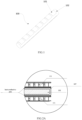
FIG. 1 illustrates a structural diagram of a cable with cooling function according to an embodiment of the present disclosure; -
FIGS. 2A and2B illustrate a cross-sectional view of a cable with cooling function according to an embodiment of the present disclosure; -
FIG. 3 illustrates another cross-sectional view of a cable with cooling function according to an embodiment of the present disclosure; -
FIG. 4 illustrates a first circuit diagram of a cable with cooling function according to an embodiment of the present disclosure; -
FIG. 5 illustrates a second circuit diagram of a cable with cooling function according to an embodiment of the present disclosure; -
FIG. 6 illustrates a partial enlarged view of a cable with cooling function according to an embodiment of the present disclosure; -
FIG. 7 illustrates a first flowchart of a process of adjusting an electrical signal of a semiconductor cooling module by a control module according to an embodiment of the present disclosure; -
FIG. 8 illustrates a second flowchart of a process of adjusting an electrical signal of a semiconductor cooling module by a control module according to an embodiment of the present disclosure; -
FIG. 9 illustrates a third flowchart of a process of adjusting an electrical signal of a semiconductor cooling module by a control module according to an embodiment of the present disclosure; -
FIG. 10 illustrates a cross-sectional view of a current transmission device according to an embodiment of the present disclosure; -
FIG. 11 illustrates a structural diagram of a semiconductor cooling module according to an embodiment of the present disclosure; and -
FIG. 12 illustrates a structural diagram of a computer device according to an embodiment of the present disclosure. -
- 100: cable with cooling function;
- 101: semiconductor cooling module;
- 102: conductor;
- 103: control module;
- 104: rectifier module;
- 105: temperature detector;
- 106: low-voltage harness;
- 107: insulating protective layer;
- 200: charging module;
- 300: battery module;
- 1011: alumina substrate;
- 1012: waterproof protective layer;
- 1013: semiconductor PIN layer;
- 1014: power interface;
- 1302: computer device;
- 1304: processor;
- 1306: memory;
- 1308: drive mechanism;
- 1310: input/output module;
- 1312: input device;
- 1314: output device;
- 1316: presentation device;
- 1318: graphical user interface;
- 1320: network interface;
- 1322: communication link;
- 1324: communication bus.
- The technical solutions in the embodiments of the present disclosure will be clearly and completely described below in conjunction with the drawings for the embodiments of the present disclosure. Obviously, those described are merely a part, rather than all, of the embodiments of the present disclosure. Based on the embodiments of the present disclosure, any other embodiment obtained by those of ordinary skill in the art without paying any creative effort should fall within the protection scope of the present disclosure.
- Although the embodiments of the present disclosure provide the operation steps of the methods as described in the embodiments or flowcharts, more or fewer operation steps may be included based on conventional or non-inventive labor. The step execution order listed in the embodiments is only one of various step execution orders and does not represent a unique execution order. In case of an actual system or apparatus product, the steps may be executed orderly or in parallel according to the methods illustrated in the embodiments or the drawings.
- The illustrative embodiments and the descriptions thereof herein are used to explain, rather than limiting, the present disclosure. In addition, element/members using the same or similar reference numerals in the drawings and embodiments are intend to represent the same or similar parts.
- In the prior art, the cooling of large-current conductors is mainly realized by the technologies of liquid cooling and air cooling. In which, the technology of liquid cooling requires additional cooling pipelines, pumps, heat dissipation devices, etc., and has the problems of complex system structure, extremely high requirements for safety and stability, and the increase of the cost. Limited by the mounting size and space, the technology of air cooling has the problems of low cooling efficiency and additional noises which affects the NVH of the whole vehicle.
- In order to solve the above technical problems, a novel cable with cooling function is provided in an embodiment of the present disclosure. The cable with cooling function according to the present disclosure has the advantages of simple structure, flexible size, reliable performance, no noise and no refrigerant pollution.
- Specifically, as illustrated in
FIG. 1 andFIG.5 , a cable with cooling function includes asemiconductor cooling module 101, aconductor 102 and acontrol module 103; - a cooling end of the
semiconductor cooling module 101 is disposed on at least one side of theconductor 102 to absorb heat emitted by theconductor 102; - the
semiconductor cooling module 101 is electrically connected to thecontrol module 103, and thecontrol module 103 is configured to control an electrical signal supplied to thesemiconductor cooling module 101. - In detail, the
semiconductor cooling module 101 is a heat transfer tool in principle. When current flows through a thermocouple pair formed by coupling one piece of N-type semiconductor material and one piece of P-type semiconductor material, heat is transferred from one end to the other end, so that a temperature difference is generated to form a cooling end and a hot end. Thesemiconductor cooling module 101 according to the present disclosure includes not only the cooling end, but also the hot end opposite to the cooling end. Thesemiconductor cooling module 101 may be the semiconductor cooling module existing in the prior art and may be customized according to the size of the conductor. Thesemiconductor cooling module 101 may completely or partially cover theconductor 102. - The amount of heat released or absorbed by the
semiconductor cooling module 101 is determined by the magnitude of current, so thesemiconductor cooling module 101 described herein may be configured to control, through thecontrol module 103, the electrical signals (including the current signal and the voltage signal) supplied to thesemiconductor cooling module 101, thereby achieving the effect of controlling the temperature rise of theconductor 102, so that the cable with cooling function can work at a stable temperature. - Power (e.g., low-
voltage 12V direct current) is supplied to thesemiconductor cooling module 101 by thecontrol module 103, and thecontrol module 103 can realize an access control of thesemiconductor cooling module 101 by controlling conduction of a connecting wire between thecontrol module 103 and thesemiconductor cooling module 101. During implementations, a control logic of thesemiconductor cooling module 101 may be set by a worker according to actual needs, e.g., differentsemiconductor cooling modules 101 are connected in different time periods, or different electrical signals of theconductor 102 are connected to differentsemiconductor cooling modules 101. The logic of the control of the electrical signals supplied to the semiconductor cooling module by thecontrol module 103 is not limited in the present disclosure, and any logic capable of realizing the control of the electrical signals belongs to the protection scope of the present disclosure. Through the power supply and control mode in the present disclosure, the structure of the cable with cooling function can be simplified, the cooling efficiency can be improved and the energy waste can be avoided. - The
control module 103 may be a Central Processing Unit (CPU) or any other programmable general-purpose or special-purpose microprocessor, a Digital Signal Processor (DSP), a programmable control module, an Application Specific Integrated Circuit (ASIC) or any other similar element, or combinations thereof, and the type, model, etc. of thecontrol module 103 are not specifically limited herein. - In some embodiments, in order to completely attach the
semiconductor cooling modules 101 to theconductors 102, there may be a plurality ofsemiconductor cooling modules 101 of a same size or different sizes depending on the size of the conductor. - In some embodiments, the
semiconductor cooling module 101 may have maximums overall dimension of more than 60 mm × 60 mm, a thickness of less than 4.1 mm, and a maximum cooling power of 270 W, with a maximum temperature difference in a single layer being more than 60 °C. - Further, in order to accurately control the temperature of each of the
semiconductor cooling modules 101, the plurality ofsemiconductor cooling modules 101 are electrically connected to thecontrol module 103 in parallel, so that the power supply signal of each of thesemiconductor cooling modules 101 can be independently controlled. - Further, when the models and powers of the plurality of
semiconductor cooling modules 101 are completely consistent, the plurality ofsemiconductor cooling modules 101 are electrically connected to thecontrol module 103 in series, so that the power supply signals of the plurality ofsemiconductor cooling modules 101 are consistent. - The plurality of
semiconductor cooling modules 101 may be disposed at a regular interval (e.g., 10 cm as illustrated inFIG. 1 , and the specific interval may be determined according to the temperature rise value of the semiconductor cooling modules 101) or disposed immediately (i.e., seamlessly) on a side of theconductor 102, depending on the temperature rise value of theconductor 102 in a working state. - In order to ensure the cooling effect, a ratio of a total area of the cooling end in the
semiconductor cooling module 101 to an area of theconductor 102 ranges from 3% to 95%. - In order to verify the influence of the range of the ratio of the total area of the cooling end in the
semiconductor cooling module 101 to the area of theconductor 102 on the temperature rise of theconductor 102, the inventor selects 13 cables with a same cross-sectional area, a same material and a same length, conducts a same current, adopts a different area ratio for the cooling end in each of thesemiconductor cooling modules 101 covering theconductor 102, reads temperature rise values of the cables and records them in Table 1. - The experimental method is to conduct a same current, in a closed environment, to each cable having a different ratio of the total area of the cooling end in the
semiconductor cooling module 101 to the area of theconductor 102, record a temperature before current conduction and a stable temperature after current conduction, and take an absolute value of a difference therebetween. In this embodiment, a temperature rises less than 50 K is a qualified value.Table 1: Influence of the Ratio of the Total Area of the Cooling End in the Semiconductor Cooling Module 101 to the Area of theConductor 102 on the Temperature Rise of the CableRatio of the total area of the cooling end in the semiconductor cooling module 101 to the area of the conductor 102 (%)1 3 5 10 20 30 40 50 60 70 80 90 95 100 Temperature rise values of the connector (K) 55.3 49.7 46.8 42.9 40.7 35.7 31.2 26.7 18.2 16.6 14.9 12.3 10.7 8.9 - As can be seen from Table 1, when the ratio of the total area of the cooling end in the
semiconductor cooling module 101 to the area of theconductor 102 is less than 3%, the temperature rise of the cable is less than the qualified value. As the ratio of the coverage area increases, the temperature rise decreases. However, during the use of the cable, there must be joints at both ends and a turning area in the middle, which cannot cover thesemiconductor cooling module 101. Therefore, the inventor sets the ratio of the total area of the cooling end in thesemiconductor cooling module 101 to the area of theconductor 102 to be 3% to 95%. - As illustrated in
FIG. 2A , thesemiconductor cooling module 101 is fixedly on theconductor 102 by heat-conductive glue. During implementations, thesemiconductor cooling module 101 may be fixed on theconductor 102 by other means, such as screw fixation, which is not limited herein. In working conditions with high requirements on the vibration resistance, thesemiconductor cooling module 101 may be fixed by an additional fixing bracket to improve the shock absorption capacity. - In order to improve the heat dissipation efficiency, the
semiconductor cooling modules 101 are disposed on both sides of theconductor 102. In a further embodiment, according to the usage of the conductor, when the cooling demand is high, multistage refrigeration can be realized by stacking a plurality of layers ofsemiconductor cooling modules 101, thereby improving the cooling capacity. As illustrated inFIG. 3 , double-layersemiconductor cooling modules 101 may also be disposed on either side of theconductor 102. - The heat generated by the
cable 100 with cooling function in this embodiment when high-voltage and large current is conducted will be absorbed by thesemiconductor cooling module 101 covering theconductor 102, so as to decrease the amount of temperature rise of the conductor, and when theconductor 102 has a fixed size, it is possible to bear larger current and meet the temperature rise requirement. - In a further embodiment of the present disclosure, as illustrated in
FIG. 4 , the cable with cooling function further includes arectifier module 104, which is electrically connected between thecontrol module 103 and theconductor 102, and configured to rectify electric energy obtained from theconductor 102 and convert the current in theconductor 102 into power supply current of thecontrol module 103. Since the current and voltage transmitted by theconductor 102 do not necessarily meet the power supply requirement of thecontrol module 103 and thesemiconductor cooling module 101, in order to obtain electric energy from theconductor 102, it is necessary to convert the current from theconductor 102 into current and voltage that can be used by thecontrol module 103 and thesemiconductor cooling module 101, through the rectifier module. - In this embodiment, the power supply may be omitted, and the
conductor 102 supplies power to the control module, which can simplify the circuit, reduce many power supply lines for thecontrol module 103 and thesemiconductor cooling module 101, and also avoid the situation that thesemiconductor cooling module 101 cannot work due to the lack of power supply from an external source. - In a further embodiment of the present disclosure, the cable with cooling function further includes at least one temperature detector disposed on the conductor and configured to detect a temperature value of the conductor; the control module is electrically connected to the temperature detector and configured to adjust the electrical signal supplied to the
semiconductor cooling module 101 according to the temperature value detected by the temperature detector. - In a further embodiment of the present disclosure, as illustrated in
FIGS. 1 ,5 and6 , the cable with cooling function further includes a plurality oftemperature detectors 105 distributed on theconductor 102 and configured to detect the temperature values of theconductor 102. During implementations, asmore temperature detectors 105 are distributed and the distribution is more uniform, the detected temperature values more conform to the actual situation. - The
control module 103 is electrically connected to thetemperature detector 105, and configured to adjust the electrical signal supplied to thesemiconductor cooling module 101 according to the temperature value detected by thetemperature detector 105. - In some embodiments, the process that the
control module 103 adjusts the electrical signal supplied to thesemiconductor cooling module 101 according to the temperature value detected by thetemperature detector 105 includes: calculating a difference between the temperature value detected by thetemperature detector 105 and a preset temperature rise value of theconductor 102; inputting the difference into a PID control strategy to obtain an electrical control signal of thesemiconductor cooling module 101; and adjusting the electrical signal supplied to thesemiconductor cooling module 101 according to the electrical control signal of thesemiconductor cooling module 101; in which control parameters in the PID control strategy are adjusted in advance according to PID control indexes. - During implementations, the preset temperature rise value may be determined according to an application scene of the conductor and a maximum temperature rise value that the conductor can bear, and is not specifically limited herein.
- After being added with the temperature control function, the cable with cooling function according to the embodiment may detect the temperature and control the heat absorption amount in real time, and realize closed-loop control. The temperature rise of the conductor may be controlled differently according to the current carrying capacity of the conductor under different conditions.
- In a specific embodiment, as illustrated in
FIG. 7 , when there is a plurality oftemperature detectors 105, thecontrol module 103 adjusts the electrical signal supplied to thesemiconductor cooling module 101 according to the temperature values detected by thetemperature detectors 105, including: - Step 701: calculating a temperature distribution of the
conductor 102 according to the temperature values detected by thetemperature detectors 105. - During implementations, the temperature distribution of the
conductor 102 may be established by a B-spline interpolation method or any other modeling method. The process of establishing the temperature distribution is not specifically limited herein. - Step 702: determining the power supply signal of each of the
semiconductor cooling modules 101 on theconductor 102 according to the temperature distribution of theconductor 102. - In this step, as the temperature of the
conductor 102 rises, the power supply signal of the correspondingsemiconductor cooling module 101 increases. During implementations, thecontrol module 103 may determine the power supply signal of each of thesemiconductor cooling modules 101 on theconductor 102 according to a preset temperature adjustment strategy (as shown in Table 2).Table 2: Correspondence Between the Temperature Range of the Conductor Detected by the Temperature Detector and the Power Supply Current of the Control Module Temperature range (°C) Current (A) X1~X2 Y1 X2~X3 Y2 ...... ...... - Step 703: supplying power to each of the
semiconductor cooling modules 101 according to the power supply signal thereof. - In an embodiment of the present disclosure, in
Step 702, determining the power supply signal of each of thesemiconductor cooling modules 101 on theconductor 102 according to the temperature distribution of theconductor 102 includes: - Step 7021: calculating a difference distribution according to the temperature distribution of the
conductor 102 and a preset temperature rise value of theconductor 102; - Step 7022: adjusting the electrical signal supplied to the
semiconductor cooling module 101 according to the difference distribution. - During implementations, step 7022 includes inputting the difference distribution into a PID control strategy to obtain a control signal of the electrical signal of the
semiconductor cooling module 101; and adjusting the electrical signal supplied to thesemiconductor cooling module 101 according to the electrical control signal of thesemiconductor cooling module 101; in which control parameters in the PID control strategy are adjusted in advance according to PID control indexes. - In the further embodiment of the present disclosure, in order to more accurately adjust the electrical signal of the
semiconductor cooling module 101, thecontrol module 103 is further electrically connected to acharging module 200 to which theconductor 102 is connected, and configured to obtain a charging and discharging current value and a charging duration, and adjust the electrical signal supplied to thesemiconductor cooling module 101 according to the charging and discharging current value, the charging duration and the temperature value detected by the temperature detector. - Specifically, as illustrated in
FIG. 8 , thecontrol module 103 adjusts the electrical signal supplied to the semiconductor cooling module according to the charging and discharging current value, the charging duration and the temperature value detected by the temperature detector, including:
Step 801: calculating a conductor calorific generation according to the charging and discharging current value and the charging duration. - In this step, the conductor calorific generation may be calculated as Q=I2×R × t, where Q denotes the conductor calorific generation, I denotes the charging and discharging current value, t denotes the charging duration, and R denotes a resistance of the conductor.
- Step 802: calculating a theoretical temperature rise value of the conductor according to the conductor calorific generation and material information of the conductor.
- The conductor calorific generation is a charging and discharging heating value. In this step, the theoretical temperature rise value of the conductor may be calculated by the following formula, which may be obtained by fitting test data obtained from a temperature rise experiment of the conductor:

where τw denotes the theoretical temperature rise, Q denotes the conductor calorific generation, t denotes the charging duration, A denotes an effective heat dissipation area, KT denotes a surface comprehensive heat dissipation coefficient of conductor, and A and KT denote the material information of the conductor. - According to the heating value and the material information of the conductor, the theoretical temperature rise value of the conductor may be calculated with reference to the prior art, which is not limited herein.
- Step 803: calculating an actual temperature rise value of the conductor according to the temperature value detected by the temperature detector and the theoretical temperature rise value of the conductor.
- The execution process of this step includes: firstly, determining a temperature rise correction coefficient according to the temperature value detected by the temperature detector. Specifically, if the temperature value detected by the temperature detector is greater than a standard temperature value for the calculation of the temperature rise, the temperature correction coefficient is greater than 1, which increases as the temperature detected by the temperature detector rises. If the temperature value detected by the temperature detector is less than the standard temperature value for the calculation of the temperature rise, the temperature correction coefficient is less than 1, which decreases as the temperature value detected by the temperature detector drops. The actual temperature rise value of the conductor is calculated by the following formula:

where τw denotes the theoretical temperature rise value, Kw denotes the temperature correction coefficient, and τdenotes the actual temperature rise value. - Step 804: adjusting the electrical signal supplied to the semiconductor cooling module according to the actual temperature rise value of the conductor.
- According to the embodiment, it is possible to adjust the electrical signal of the
semiconductor cooling module 101 according to the actual temperature rise predicted in advance in conjunction with the charging and discharging information and the temperature value detected by the temperature detector, so that the temperature of the conductor can reach the working temperature as soon as possible, thereby improving the efficiency and accuracy of the temperature control. - In a further embodiment of the present disclosure, as illustrated in
FIG. 9 , in order to make the current adjustment of thesemiconductor cooling module 101 have an automatic adjustment capability, adjusting the electrical signal supplied to the semiconductor cooling module according to the actual temperature rise value of the conductor inStep 804 includes: - Step 901: calculating a difference between the actual temperature rise value of the
conductor 102 and a preset temperature rise value of theconductor 102; - Step 902: inputting the difference into a PID control strategy to obtain the electrical control signal of the
semiconductor cooling module 101. - During implementation of this step, the electrical control signal of the
semiconductor cooling module 101 is generated only when there is a deviation between the actual temperature rise value of theconductor 102 and the preset temperature rise. When the actual temperature rise value of theconductor 102 is equal to the preset temperature rise, the temperature of theconductor 102 may be controlled below the preset temperature rise to ensure the safety of theconductor 102, and no electrical control signal of thesemiconductor cooling module 101 will be generated at this time. - In which, control parameters in the PID control strategy are adjusted in advance according to PID control indexes. The PID control strategy includes three parts, i.e., proportional control, integral control and differential control. The PID control indexes include: rise time, overshoot, adjustment time and steady-state error. For the adjustment of the control parameters in the PID control strategy, please refer to the prior art and it will not be described in detail here.
- Step 903: adjusting the electrical signal supplied to the
semiconductor cooling module 101 according to the electrical control signal of thesemiconductor cooling module 101. - In a further embodiment of the present disclosure, in order to improve the temperature control accuracy of the conductor and make the calculated value more conform to the actual situation, the
control module 103 is further electrically connected to an environmental parameter detection module and acharging module 200 to which the conductor is connected, and configured to obtain environmental parameter information from the environmental parameter detection module and obtain a charging and discharging current value and a charging duration from the charging module; and adjust the electrical signal supplied to the semiconductor cooling module according to the environmental parameter information, the charging and discharging current value and the charging duration. - In detail, the environmental parameter information includes but is not limited to: environmental humidity, environmental temperature, environmental pressure, etc.
- Adjusting the electrical signal supplied to the
semiconductor cooling module 101 according to the environmental parameter information, the charging and discharging current value and the charging duration includes: - (1) Calculating a conductor calorific generation according to the charging and discharging current value and the charging duration.
- (2) Calculating a theoretical temperature rise value of the
conductor 102 according to the conductor calorific generation and material information of the conductor. - (3) Calculating an actual temperature rise value of the
conductor 102 according to the environmental parameter information and the theoretical temperature rise value of theconductor 102.
The execution process of this step includes: firstly, determining a temperature rise correction coefficient according to the environmental parameter information; specifically, calculating a correction coefficient for each environmental parameter information (please refer to the temperature correction coefficient described in the above embodiment for the calculation process of each correction coefficient, which will not be described in detail here), and weighted-summing (as shown in Formula 1 below) or multiplying (as shown in Formula 2 below) the correction coefficients corresponding to all the environmental parameter information to obtain a final correction coefficient; and multiplying the final correction coefficient by the theoretical temperature rise value of theconductor 102 to calculate the actual temperature rise value of theconductor 102.

where K denotes the final correction coefficient; a 1 ... an denote known quantities and may be determined according to the importance of the environmental parameters; a denotes a known quantity; i denotes an i-th environmental parameter; and K w1 ... Kwn denote environmental parameter values. - (4) Adjusting the electrical signal supplied to the
semiconductor cooling module 101 according to the actual temperature rise value of theconductor 102. - In a further embodiment of the present disclosure, as illustrated in
FIG. 1 ,FIG. 6 andFIG 10 , wires connecting thesemiconductor cooling module 101 to thecontrol module 103 are disposed in a low-voltage harness 106. - In this embodiment, the wires connecting the
semiconductor cooling module 101 to thecontrol module 103 are disposed in the low-voltage harness 106, so that the lines are clear, the semiconductor cooling module can be easily adjusted and replaced, and the high-voltage and low-voltage power supply systems can be safely isolated. - In a further embodiment of the present disclosure, as illustrated in
FIG. 11 , thesemiconductor cooling module 101 includes analumina substrate 1011, a waterproofprotective layer 1012, asemiconductor PIN layer 1013, and apower interface 1014. - The
alumina substrate 1011, the waterproofprotective layer 1012, and thesemiconductor PIN layer 1013 are disposed in sequence. Thepower interface 1014 is electrically connected to thesemiconductor PIN layer 1013. - The
alumina substrate 1011 constitutes a hot end of thesemiconductor cooling module 101, i.e., a heat dissipation end. Thesemiconductor PIN layer 1013 constitutes a cooling end of thesemiconductor cooling module 101, i.e., a heat absorption end. - In this embodiment, by taking the
alumina substrate 1011 as the surface of the semiconductor cooling module, the thermal conductivity is improved, the heat transfer speed is increased, the cooling time is shortened, and the bearable strength is increased. Thus, thealumina substrate 1011 can be flexibly connected and better attached to the conductor, so as to effectively absorb a surface stress at a bent part of the conductor, and it will not be easily broken during mounting and use. The core of the semiconductor cooling module adopts a P-N junction made of special semiconductor materials. When current flows through a thermocouple pair formed by coupling one piece of N-type semiconductor material and one piece of P-type semiconductor material, heat is transferred from one end to the other end, so that a temperature difference is generated to form a cooling end and a hot end, i.e., a refrigeration control can be realized by controlling the DC current. - The
semiconductor cooling module 101 has a cooling rate of 0.05 K/s to 5K/s. - In order to verify the influence of the cooling rate of the
semiconductor cooling module 101 on the temperature rise value of theconductor 102, the inventor selects 10 cables with a same cross-sectional area, a same material and a same length, conducts a same current, adopts thesemiconductor cooling modules 101 with different cooling rates to cool the cables, reads the temperature rises of the cables and records them in Table 3. - The experimental method is to conduct a same current, in a closed environment, to each cable having the
semiconductor cooling modules 101 with a different cooling rate, record a temperature before current conduction and a stable temperature after current conduction, and take an absolute value of a difference therebetween. In this embodiment, a temperature rise value less than 50 K is a qualified value.Table 3: Influence of the Cooling Rate of the Semiconductor Cooling Module 101 on the Temperature Rise of the CableCooling Rate of the Semiconductor Cooling Module 101 (K/s) 0.01 0.03 0.05 0.1 0.3 0.5 1 2 3 4 5 6 7 Temperature Rise Value of the Connector (K) 63.8 52.5 49.6 47.7 45.2 43.5 41.4 37.1 33.2 30.9 27.5 26.8 26.5 - As can be seen from Table 3, when the cooling rate of the
semiconductor cooling module 101 is less than 0.05 K/s, the temperature rise value of the cable is less than the qualified value, and the temperature rise is decreased as the cooling rate of thesemiconductor cooling module 101 increases. However, when the cooling rate of thesemiconductor cooling module 101 is greater than 5K/s, the temperature rise value is not obviously decreased under the influences of the heating value of the cable itself and the power of thesemiconductor cooling module 101 itself, but the power of thesemiconductor cooling module 101 increases, which is not economical. Therefore, the inventor sets the cooling rate of thesemiconductor cooling module 101 to be 0.05 K/s to 5 K/s. - In a further embodiment of the present disclosure, in order to ensure the safety of the conductor, an insulating
protective layer 107 is disposed around theconductor 102, as illustrated inFIGS. 2A and2B , and the insulatingprotective layer 107 is disposed between theconductor 102 and thesemiconductor cooling module 101 or on an outer side of thesemiconductor cooling module 101. - In a further embodiment of the present disclosure, the insulating
protective layer 107 is made of one or combinations of polyvinyl chloride, polyurethane, nylon, polypropylene, silicone rubber, crosslinked polyolefin, synthetic rubber, polyurethane elastomer, crosslinked polyethylene and polyethylene. - Further, in order to prevent the conductor from being burnt due to fire, a fire-resistant layer is disposed outside the insulating protective layer.
- In a further embodiment of the present disclosure, a cross section of the
conductor 102 is circular or elliptical or rectangular or polygonal or E-shaped or F-shaped or H-shaped or K-shaped or L-shaped or T-shaped or U-shaped or V-shaped or W-shaped or X-shaped or Y-shaped or Z-shaped or arc-shaped or wave-shaped, in which an arc includes a semi-arc, an acute-angle arc, an obtuse-angle, etc. The cross section of theconductor 102 is designed into various shapes, which is convenient for a designer to select different shapes for the cross section of theconductor 102 according to the actual layout environment, reduce the volume of the cable, optimize the cable assembly environment and improve the safety of the cable. - In a further embodiment of the present disclosure, the
conductor 102 described herein may be made of one or combinations of metal, conductive ceramic, carbon-containing conductor, solid electrolyte, mixed conductor and conductive polymeric material. - During implementations, the
conductor 102 described herein is made of copper or copper alloy, or aluminum or aluminum alloy. Because of high voltage and large current, the cables of the electric vehicle need to use wires with a large diameter for current conduction. The conductor material made of copper has good conductivity and ductility, and is the preferred conductor material for the cables. However, with the increasing price of copper, the material cost of the conductor made of copper is higher and higher. To this end, people begin to look for alternatives to copper to reduce costs. The content of metallic aluminum in the earth's crust is about 7.73%, and after the optimization of the refining technology, the price thereof is relatively low. In addition, compared with copper, aluminum is lighter, and its conductivity is second only to copper, so that aluminum can partially replace copper in the field of electrical connections. Therefore, it is a development trend to replace copper with aluminum in the field of automotive electrical connections. - In a further embodiment of the present disclosure, in order to further improve the heat dissipation effect, the cable with cooling function further includes a heat dissipation device disposed on an outer side of the
semiconductor cooling module 101. During implementations, the heat dissipation device may be close to or tightly attached to the outer side of thesemiconductor cooling module 101, depending on the type of the heat dissipation device. - The heat dissipation device described herein includes but is not limited to a fan, a heat exchanger, a liquid cooling device and heat dissipation fins, in which the heat dissipation fins are preferably made of metal. In which, the large device such as the fan, the heat exchanger, or the liquid cooling device is disposed close to the
semiconductor cooling module 101, and the cooling fins are tightly attached to thesemiconductor cooling module 101. In a further embodiment of the present disclosure, as illustrated inFIG. 5 , a current transmission device is further provided, including thecable 100 with cooling function according to any of the aforementioned embodiments, acharging module 200 and abattery module 300. - Two ends of the
cable 100 with cooling function are respectively connected to thecharging module 200 and thebattery module 300, to conduct electric energy obtained by thecharging module 200 to thebattery module 300. - In some embodiments, the
charging module 200 described herein is a fast charging stand, and thebattery module 300 is a Battery Management System (BMS) battery management module. - In a further embodiment of the present disclosure, the
control module 103 is further connected to thecharging module 200 which supplies electric energy to thecontrol module 103. - In a further embodiment of the present disclosure, there is further provided an electric vehicle, including the current transmission device according to any of the above embodiments.
- In a further embodiment of the present disclosure, the method performed by the control module may be performed in a computer device, such as a central control device, as illustrated in
FIG. 12 , which may include one ormore processors 1304, such as one or more central processing units (CPUs) each implementing one or more hardware threads. Thecomputer device 1302 may further include anymemory 1306 configured to store any type of information such as codes, settings, data, etc. Without limitation, for example, thememory 1306 may include any or combinations of any type of RAM, any type of ROM, a flash memory device, a hard disk, an optical disk, etc. More generally, any memory may store information using any technology. Further, any memory may provide volatile or nonvolatile retention of information. Further, any memory may represent a fixed or removable component of thecomputer device 1302. In a case where theprocessor 1304 executes associated instructions stored in any memory or combination of memories, thecomputer device 1302 may perform any operation of the associated instructions. Thecomputer device 1302 further includes one ormore drive mechanisms 1308 interacted with any memory, such as a hard disk drive mechanism, an optical disk drive mechanism, etc. - The
computer device 1302 may further include an input/output module 1310(I/O) configured to receive various inputs (via an input device 1312) and provide various outputs (via an output device 1314). A specific output mechanism may include apresentation device 1316 and an associated graphical user interface 1318 (GUI). In other embodiments, the input/output module 1310 (I/O), theinput device 1312, and theoutput device 1314 may not be included, and the output mechanism only serves as a computer device in a network, thecomputer device 1302 may further include one ormore network interfaces 1320 configured to exchange data with other devices via one ormore communication links 1322. One ormore communication buses 1324 couple the components described above together. - The
communication link 1322 may be implemented in any manner, for example, through a local area network, a wide area network (e.g., the Internet), a point-to-point connection, etc., or any combination thereof. Thecommunication link 1322 may include any combination of a hardwired link, a wireless link, a router, a gateway function, a name server, etc. governed by any protocol or combination of protocols. - In correspondence to the method in
FIGS. 7 to 9 , the embodiments of the present disclosure further provide a computer-readable storage medium which stores a computer program, in which when executed by a processor, the computer program perform the steps of the aforementioned method. - The embodiments of the present disclosure further provide a computer-readable instruction, in which when the instruction is executed by a processor, a program therein enables the processor to perform the method as illustrated in
FIGS. 7 to 9 . - It should be understood that in various embodiments of the present disclosure, the serial number of each process does not indicate an execution order that should be determined according to the function and the internal logic thereof, and the serial number of each process also does not restrict the implementation process of the embodiments herein.
- It should also be understood that in the embodiments of the present disclosure, the term 'and/or' is merely an association relationship describing the associated objects, and indicates that there may be three relationships. For example, A and/or B may indicate that A exists alone, A and B exist simultaneously, and B exists alone. In addition, the character '/' herein generally indicates that the associated objects are in an 'or' relationship.
- Those skilled in the art can appreciate that the units and algorithm steps of the examples described in conjunction with the embodiments disclosed herein can be implemented by electronic hardware, computer software or a combination thereof, and in order to clearly illustrate the interchangeability between hardware and software, the compositions and steps of the examples have been generally described as above in terms of functions. Whether these functions are performed in hardware or software depends on the particular application and design constraints of the technical solution. Professionals can implement the described functions using different methods for each particular application, but such implementation should not be considered as going beyond the scope of the present disclosure.
- It can be clearly understood by those skilled in the art that for the convenience and conciseness of the description, the specific working processes of the systems, apparatuses and units described above can refer to the corresponding processes in the foregoing method embodiments, and will not be repeated here.
- In several embodiments provided herein, it should be understood that the disclosed systems, apparatuses and methods can be implemented in other ways. For example, the apparatus embodiments described above are merely illustrative, e.g., the unit partitioning is only a logical function partitioning, and other partitioning modes are possible during the actual implementation. For example, a plurality of units or components may be combined or integrated into another system, or some features may be omitted or not executed. In addition, the mutual coupling or direct coupling or communication connection illustrated or discussed may be an indirect coupling or communication connection through some interfaces, means or units, and may be in electrical, mechanical or other forms.
- The units described as separate components may or may not be physically separated, and the components displayed as units may or may not be physical units, i.e., they may be located in one place or distributed to a plurality of network units. Some or all of the units can be selected according to the actual needs to achieve the objectives of the embodiments of the present disclosure.
- In addition, the functional units in the embodiments of the present disclosure may be integrated into one processing unit, or each unit may be existed physically alone, or two or more units may be integrated into one unit. The integrated unit may be implemented in the form of hardware or a software functional unit.
- If being implemented in the form of a software functional unit and sold or used as an independent product, the integrated unit may be stored in a computer readable storage medium. Based on such understanding, the essence of the technical solutions of the present disclosure, i.e., portions making contributions to the prior art, or all or part of the technical solutions may be embodied in the form of a computer software product, which is stored in a storage medium and includes several instructions for causing a computer device (e.g., a personal computer, a server, a network device, etc.) to perform all or part of the steps of the methods described in the embodiments of the present disclosure. The foregoing storage medium includes various media that can store program codes, such as a USB flash disk, a mobile hard disk, a Read-Only Memory (ROM), a Random-Access Memory (RAM), a magnetic disk, or an optical disk.
- Specific embodiments are used herein to explain the principles and the implementations of the present disclosure, and the descriptions of the above embodiments are only intended to help understanding of the method and the core idea of the present disclosure. Meanwhile, those of ordinary skilled in the art can modify the implementations and the application scope according to the concept of the present disclosure. To sum up, the content of this specification should not be construed as limitations to the present disclosure.
Claims (24)
- A cable with cooling function, comprising a semiconductor cooling module (101), a conductor (102) and a control module (103);a cooling end of the semiconductor cooling module (101) is disposed on at least one side of the conductor (102) to absorb heat dissipated from the conductor (102);the semiconductor cooling module (101) is electrically connected to the control module (103), and the control module (103) is configured to control an electrical signal supplied to the semiconductor cooling module (101).
- The cable with cooling function according to claim 1, wherein there are a plurality of semiconductor cooling modules (101) which are connected to the control module (103) in parallel.
- The cable with cooling function according to claim 1, wherein there are a plurality of semiconductor cooling modules (101) which are connected to the control module (103) in series.
- The cable with cooling function according to claim 2 or 3, wherein the plurality of semiconductor cooling modules (101) are disposed on at least one side of the conductor (102) at a predetermined interval of distance.
- The cable with cooling function according to claim 1, wherein a ratio of a total area of the cooling end in the semiconductor cooling module (101) to an area of the conductor (102) ranges from 3% to 95%.
- The cable with cooling function according to claim 1, further comprising a rectifier module (104) electrically connected between the control module (103) and the conductor (102) and configured to rectify electric energy obtained from the conductor (102).
- The cable with cooling function according to claim 1, further comprising: at least one temperature detector (105) disposed on the conductor (102) and configured to detect a temperature value of the conductor (102);
the control module (103) is electrically connected to the temperature detector (105) and configured to adjust the electrical signal supplied to the semiconductor cooling module (101) according to the temperature value detected by the temperature detector (105). - The cable with cooling function according to claim 7, wherein when there are a plurality of temperature detectors (105), adjusting the electrical signal supplied to the semiconductor cooling module (101) according to the temperature value detected by the temperature detector (105) comprises:calculating a temperature distribution of the conductor (102) according to the temperature values detected by the temperature detectors (105);determining a power supply signal of each of the semiconductor cooling modules (101) on the conductor (102) according to the temperature distribution of the conductor (102); andsupplying power to each of the semiconductor cooling modules (101) according to the power supply signal thereof.
- The cable with cooling function according to claim 7, wherein the control module (103) is further electrically connected to a charging module (200) to which the conductor (102) is connected, and configured to obtain a charging and discharging current value and a charging duration, and adjust the electrical signal supplied to the semiconductor cooling module (101) according to the charging and discharging current value, the charging duration and the temperature value detected by the temperature detector (105).
- The cable with cooling function according to claim 9, wherein adjusting, by the control module (103), the electrical signal supplied to the semiconductor cooling module (101) according to the charging and discharging current value, the charging duration and the temperature value detected by the temperature detector (105) comprises:calculating a conductor calorific generation according to the charging and discharging current value and the charging duration;calculating a theoretical temperature rise value of the conductor (102) according to the conductor calorific generation and material information of the conductor (102);calculating a theoretical temperature rise value of the conductor according to the conductor calorific generation and material information of the conductor.calculating an actual temperature rise value of the conductor (102) according to the temperature value detected by the temperature detector (105) and the theoretical temperature rise value of the conductor (102); andadjusting the electrical signal supplied to the semiconductor cooling module (101) according to the actual temperature rise value of the conductor (102).
- The cable with cooling function according to claim 10, wherein adjusting the electrical signal supplied to the semiconductor cooling module (101) according to the actual temperature rise value of the conductor (102) comprises:calculating a difference between the actual temperature rise value of the conductor (102) and a preset temperature rise value of the conductor (102);inputting the difference into a PID control strategy to obtain an electric control signal of the semiconductor cooling module (101); andadjusting the electrical signal supplied to the semiconductor cooling module (101) according to the electrical control signal of the semiconductor cooling module (101),wherein control parameters in the PID control strategy are adjusted in advance according to PID control indexes.
- The cable with cooling function according to claim 7, wherein the control module (103) is further electrically connected to an environmental parameter detection module and a charging module (200) to which the conductor (102) is connected, and configured to obtain environmental parameter information from the environmental parameter detection module and obtain a charging and discharging current value and a charging duration from the charging module (200); and adjust the electrical signal supplied to the semiconductor cooling module (101) according to the environmental parameter information, the charging and discharging current value and the charging duration.
- The cable with cooling function according to claim 1, wherein wires connecting the semiconductor cooling module (101) to the control module (103) are disposed in a low-voltage harness (106).
- The cable with cooling function according to claim 1, wherein the semiconductor cooling module (101) comprises an alumina substrate (1011), a waterproof protective layer (1012), a semiconductor PIN layer (1013) and a power interface (1014);the alumina substrate (1011), the waterproof protection layer (1012) and the semiconductor PIN layer (1013) are disposed in sequence; andthe power interface (1014) is electrically connected to the semiconductor PIN layer (1013).
- The cable with cooling function according to claim 14, wherein the semiconductor cooling module (101) has a cooling rate of 0.05 K/s to 5K/s.
- The cable with cooling function according to claim 1, further comprising an insulating protective layer (107) disposed between the conductor (102) and the semiconductor cooling module (101) or disposed on an outer side of the semiconductor cooling module (101).
- The cable with cooling function according to claim 16, wherein the insulating protective layer (107) is made of one or combinations of polyvinyl chloride, polyurethane, nylon, polypropylene, silicone rubber, crosslinked polyolefin, synthetic rubber, polyurethane elastomer and polyethylene.
- The cable with cooling function according to claim 1, wherein a cross section of the conductor (102) is circular or elliptical or rectangular or polygonal or E-shaped or F-shaped or H-shaped or K-shaped or L-shaped or T-shaped or U-shaped or V-shaped or W-shaped or X-shaped or Y-shaped or Z-shaped or arc-shaped or wave-shaped.
- The cable with cooling function according to claim 1, wherein the conductor (102) is made of one or combinations of metal, conductive ceramic, carbon-containing conductor, solid electrolyte, mixed conductor and conductive polymer material.
- The cable with cooling function according to claim 19, wherein the conductor (102) is made of copper or copper alloy, or aluminum or aluminum alloy.
- The cable with cooling function according to claim 1, further comprising a heat dissipation device disposed on an outer side of the semiconductor cooling module (101).
- A current transmission device, comprising the cable (100) with cooling function according to any of claims 1 to 21, a charging module (200) and a battery module (300);
two ends of the cable (100) with cooling function are respectively connected to the charging module (200) and the battery module (300) to conduct electric energy obtained by the charging module (200) to the battery module (300). - The current transmission device according to claim 22, wherein the control module (103) is connected to the charging module (200) which supplies electric energy to the control module (103).
- An electric vehicle, comprising the current transmission device according to claim 22 or 23.
Applications Claiming Priority (3)
| Application Number | Priority Date | Filing Date | Title |
|---|---|---|---|
| CN202121653535.0U CN215911237U (en) | 2021-07-20 | 2021-07-20 | Cable with cooling function, current transmission equipment and electric automobile |
| CN202110821578.3A CN113488282B (en) | 2021-07-20 | 2021-07-20 | Cable with cooling function, current transmission equipment and electric automobile |
| PCT/CN2022/106259 WO2023001104A1 (en) | 2021-07-20 | 2022-07-18 | Cable having cooling function, current transmission device, and electric vehicle |
Publications (4)
| Publication Number | Publication Date |
|---|---|
| EP4376028A1 true EP4376028A1 (en) | 2024-05-29 |
| EP4376028A4 EP4376028A4 (en) | 2025-01-08 |
| EP4376028B1 EP4376028B1 (en) | 2026-02-25 |
| EP4376028C0 EP4376028C0 (en) | 2026-02-25 |
Family
ID=84979997
Family Applications (1)
| Application Number | Title | Priority Date | Filing Date |
|---|---|---|---|
| EP22845269.4A Active EP4376028B1 (en) | 2021-07-20 | 2022-07-18 | Cable having cooling function, current transmission device, and electric vehicle |
Country Status (10)
| Country | Link |
|---|---|
| US (1) | US20240257993A1 (en) |
| EP (1) | EP4376028B1 (en) |
| JP (1) | JP7733804B2 (en) |
| KR (1) | KR102841833B1 (en) |
| BR (1) | BR112024001184A2 (en) |
| CA (1) | CA3226481A1 (en) |
| ES (1) | ES3064845T3 (en) |
| MX (1) | MX2024001061A (en) |
| WO (1) | WO2023001104A1 (en) |
| ZA (1) | ZA202400625B (en) |
Families Citing this family (2)
| Publication number | Priority date | Publication date | Assignee | Title |
|---|---|---|---|---|
| CN118866454B (en) * | 2024-09-27 | 2024-12-10 | 浙江启超电缆股份有限公司 | A self-cooling cable |
| CN119650178B (en) * | 2025-02-14 | 2025-05-16 | 山西金广丰线缆有限公司 | High-temperature-resistant multifunctional cable |
Family Cites Families (15)
| Publication number | Priority date | Publication date | Assignee | Title |
|---|---|---|---|---|
| JPS6048845B2 (en) * | 1978-11-16 | 1985-10-29 | 株式会社フジクラ | Thermoelectrically cooled power cable |
| US5079618A (en) * | 1990-06-12 | 1992-01-07 | Micron Technology, Inc. | Semiconductor device structures cooled by Peltier junctions and electrical interconnect assemblies |
| JPH07162039A (en) * | 1993-12-10 | 1995-06-23 | Sharp Corp | Thermoelectric conversion device, heat exchange element, and device using them |
| JP4599584B2 (en) * | 2001-07-13 | 2010-12-15 | 中部電力株式会社 | Power cable cooling system |
| JP2006287112A (en) * | 2005-04-04 | 2006-10-19 | Toyota Motor Corp | Semiconductor device and vehicle |
| US10341125B2 (en) * | 2016-12-29 | 2019-07-02 | Nexans | Active cooling arrangement for power over ethernet arrangements |
| CN207474759U (en) * | 2017-11-20 | 2018-06-08 | 常州市华晟福涛光电科技有限公司 | A kind of Domestic anti-theft new-energy automobile charging gun |
| CN207652897U (en) * | 2017-12-29 | 2018-07-24 | 北京冠洁超能新能源科技有限公司 | A kind of charging equipment cooling device based on peltier effect |
| DE102018120932B4 (en) * | 2018-08-28 | 2021-02-18 | Volkswagen Aktiengesellschaft | Cable section, system and method for power transmission within a motor vehicle and a motor vehicle, having a cable section |
| CN208781982U (en) * | 2018-09-20 | 2019-04-23 | 山东天瀚新能源科技有限公司 | A kind of Li-ion batteries piles with temperature detecting function |
| CN111293510A (en) * | 2018-12-06 | 2020-06-16 | 江苏万帮德和新能源科技股份有限公司 | Charging connection device for vehicle |
| CN111426891B (en) * | 2019-11-19 | 2022-08-12 | 杭州大和热磁电子有限公司 | Cooling and heating device for electronic equipment test and control method thereof |
| CN212579636U (en) * | 2020-04-13 | 2021-02-23 | 中国电器科学研究院股份有限公司 | Semiconductor refrigeration type direct current charging plug for electric automobile |
| CN113488282B (en) * | 2021-07-20 | 2025-08-12 | 长春捷翼汽车科技股份有限公司 | Cable with cooling function, current transmission equipment and electric automobile |
| CN215911237U (en) * | 2021-07-20 | 2022-02-25 | 长春捷翼汽车零部件有限公司 | Cable with cooling function, current transmission equipment and electric automobile |
-
2022
- 2022-07-18 EP EP22845269.4A patent/EP4376028B1/en active Active
- 2022-07-18 MX MX2024001061A patent/MX2024001061A/en unknown
- 2022-07-18 US US18/290,653 patent/US20240257993A1/en active Pending
- 2022-07-18 CA CA3226481A patent/CA3226481A1/en active Pending
- 2022-07-18 BR BR112024001184A patent/BR112024001184A2/en unknown
- 2022-07-18 WO PCT/CN2022/106259 patent/WO2023001104A1/en not_active Ceased
- 2022-07-18 ES ES22845269T patent/ES3064845T3/en active Active
- 2022-07-18 JP JP2024503751A patent/JP7733804B2/en active Active
- 2022-07-18 KR KR1020247001101A patent/KR102841833B1/en active Active
-
2024
- 2024-01-18 ZA ZA2024/00625A patent/ZA202400625B/en unknown
Also Published As
| Publication number | Publication date |
|---|---|
| KR102841833B1 (en) | 2025-08-04 |
| KR20240019348A (en) | 2024-02-14 |
| BR112024001184A2 (en) | 2024-04-30 |
| ZA202400625B (en) | 2024-09-25 |
| EP4376028B1 (en) | 2026-02-25 |
| EP4376028C0 (en) | 2026-02-25 |
| WO2023001104A1 (en) | 2023-01-26 |
| EP4376028A4 (en) | 2025-01-08 |
| ES3064845T3 (en) | 2026-04-29 |
| JP2024527851A (en) | 2024-07-26 |
| JP7733804B2 (en) | 2025-09-03 |
| US20240257993A1 (en) | 2024-08-01 |
| MX2024001061A (en) | 2024-02-27 |
| CA3226481A1 (en) | 2023-01-26 |
Similar Documents
| Publication | Publication Date | Title |
|---|---|---|
| CN215911237U (en) | Cable with cooling function, current transmission equipment and electric automobile | |
| EP4376028A1 (en) | Cable having cooling function, current transmission device, and electric vehicle | |
| Christensen et al. | An efficient parallelizable 3D thermoelectrochemical model of a Li-ion cell | |
| US9457681B2 (en) | Method for high-current rapid charging | |
| CN106255392A (en) | Heat dissipation control method, device and system for electrical cabinet | |
| EP4574542A1 (en) | Charging terminal | |
| EP4376564A1 (en) | Connector having semiconductor cooling device, and automobile | |
| WO2012098843A1 (en) | Cell system | |
| US20220013828A1 (en) | Battery Pack | |
| CN115000470A (en) | Fuel cell temperature control system and temperature control method thereof | |
| CN113488282B (en) | Cable with cooling function, current transmission equipment and electric automobile | |
| WO2024260087A1 (en) | Heat dissipation structure and connection port structure having same | |
| KR20250032796A (en) | A heat dissipation current guide connection device | |
| CN115805824B (en) | Method for detecting state of charging gun temperature sensor, charging device and charging system | |
| CN218124958U (en) | A kind of PTC heater | |
| CN204928300U (en) | Balanced cooling system of lithium cell | |
| CN202196841U (en) | Polymer battery cell module | |
| CN213693078U (en) | Bus duct capable of being safely used in high-temperature environment | |
| CN115932616A (en) | Air-cooled power test method for batteries | |
| CN109786884A (en) | Fast charging type lithium battery pack and its heat management and cooling device | |
| Awais et al. | Enhanced thermal management strategies for SiC MOSFETs in EV fast charging systems using cold plate and copper inlay solution | |
| CN223110367U (en) | An electronic speed regulator with good heat dissipation | |
| CN221467349U (en) | Dense bus duct of rotational symmetry fin conductor | |
| CN204721009U (en) | Electric power controller | |
| CN207200363U (en) | Split type electrical door stand-by power supply |
Legal Events
| Date | Code | Title | Description |
|---|---|---|---|
| STAA | Information on the status of an ep patent application or granted ep patent |
Free format text: STATUS: THE INTERNATIONAL PUBLICATION HAS BEEN MADE |
|
| PUAI | Public reference made under article 153(3) epc to a published international application that has entered the european phase |
Free format text: ORIGINAL CODE: 0009012 |
|
| STAA | Information on the status of an ep patent application or granted ep patent |
Free format text: STATUS: REQUEST FOR EXAMINATION WAS MADE |
|
| 17P | Request for examination filed |
Effective date: 20240205 |
|
| AK | Designated contracting states |
Kind code of ref document: A1 Designated state(s): AL AT BE BG CH CY CZ DE DK EE ES FI FR GB GR HR HU IE IS IT LI LT LU LV MC MK MT NL NO PL PT RO RS SE SI SK SM TR |
|
| P01 | Opt-out of the competence of the unified patent court (upc) registered |
Free format text: CASE NUMBER: APP_36016/2024 Effective date: 20240617 |
|
| DAV | Request for validation of the european patent (deleted) | ||
| DAX | Request for extension of the european patent (deleted) | ||
| A4 | Supplementary search report drawn up and despatched |
Effective date: 20241205 |
|
| RIC1 | Information provided on ipc code assigned before grant |
Ipc: H01B 7/42 20060101AFI20241129BHEP |
|
| GRAP | Despatch of communication of intention to grant a patent |
Free format text: ORIGINAL CODE: EPIDOSNIGR1 |
|
| STAA | Information on the status of an ep patent application or granted ep patent |
Free format text: STATUS: GRANT OF PATENT IS INTENDED |
|
| INTG | Intention to grant announced |
Effective date: 20250929 |
|
| GRAS | Grant fee paid |
Free format text: ORIGINAL CODE: EPIDOSNIGR3 |
|
| GRAA | (expected) grant |
Free format text: ORIGINAL CODE: 0009210 |
|
| STAA | Information on the status of an ep patent application or granted ep patent |
Free format text: STATUS: THE PATENT HAS BEEN GRANTED |
|
| AK | Designated contracting states |
Kind code of ref document: B1 Designated state(s): AL AT BE BG CH CY CZ DE DK EE ES FI FR GB GR HR HU IE IS IT LI LT LU LV MC MK MT NL NO PL PT RO RS SE SI SK SM TR |
|
| REG | Reference to a national code |
Ref country code: CH Ref legal event code: F10 Free format text: ST27 STATUS EVENT CODE: U-0-0-F10-F00 (AS PROVIDED BY THE NATIONAL OFFICE) Effective date: 20260225 Ref country code: GB Ref legal event code: FG4D |
|
| REG | Reference to a national code |
Ref country code: DE Ref legal event code: R096 Ref document number: 602022031307 Country of ref document: DE |
|
| REG | Reference to a national code |
Ref country code: IE Ref legal event code: FG4D |
|
| U01 | Request for unitary effect filed |
Effective date: 20260306 |
|
| U07 | Unitary effect registered |
Designated state(s): AT BE BG DE DK EE FI FR IT LT LU LV MT NL PT RO SE SI Effective date: 20260312 |
|
| P04 | Withdrawal of opt-out of the competence of the unified patent court (upc) registered |
Free format text: CASE NUMBER: APP_36016_1/2024 Effective date: 20260312 |
|
| REG | Reference to a national code |
Ref country code: ES Ref legal event code: FG2A Ref document number: 3064845 Country of ref document: ES Kind code of ref document: T3 Effective date: 20260429 |