EP4375972A1 - Display screen and display apparatus - Google Patents
Display screen and display apparatus Download PDFInfo
- Publication number
- EP4375972A1 EP4375972A1 EP21839809.7A EP21839809A EP4375972A1 EP 4375972 A1 EP4375972 A1 EP 4375972A1 EP 21839809 A EP21839809 A EP 21839809A EP 4375972 A1 EP4375972 A1 EP 4375972A1
- Authority
- EP
- European Patent Office
- Prior art keywords
- composite portion
- holes
- support member
- display screen
- layer
- Prior art date
- Legal status (The legal status is an assumption and is not a legal conclusion. Google has not performed a legal analysis and makes no representation as to the accuracy of the status listed.)
- Pending
Links
Images



Classifications
-
- H—ELECTRICITY
- H05—ELECTRIC TECHNIQUES NOT OTHERWISE PROVIDED FOR
- H05K—PRINTED CIRCUITS; CASINGS OR CONSTRUCTIONAL DETAILS OF ELECTRIC APPARATUS; MANUFACTURE OF ASSEMBLAGES OF ELECTRICAL COMPONENTS
- H05K5/00—Casings, cabinets or drawers for electric apparatus
- H05K5/02—Details
- H05K5/03—Covers
-
- G—PHYSICS
- G06—COMPUTING OR CALCULATING; COUNTING
- G06F—ELECTRIC DIGITAL DATA PROCESSING
- G06F1/00—Details not covered by groups G06F3/00 - G06F13/00 and G06F21/00
- G06F1/16—Constructional details or arrangements
- G06F1/1613—Constructional details or arrangements for portable computers
- G06F1/1633—Constructional details or arrangements of portable computers not specific to the type of enclosures covered by groups G06F1/1615 - G06F1/1626
- G06F1/1637—Details related to the display arrangement, including those related to the mounting of the display in the housing
- G06F1/1652—Details related to the display arrangement, including those related to the mounting of the display in the housing the display being flexible, e.g. mimicking a sheet of paper, or rollable
-
- G—PHYSICS
- G09—EDUCATION; CRYPTOGRAPHY; DISPLAY; ADVERTISING; SEALS
- G09F—DISPLAYING; ADVERTISING; SIGNS; LABELS OR NAME-PLATES; SEALS
- G09F9/00—Indicating arrangements for variable information in which the information is built-up on a support by selection or combination of individual elements
- G09F9/30—Indicating arrangements for variable information in which the information is built-up on a support by selection or combination of individual elements in which the desired character or characters are formed by combining individual elements
- G09F9/301—Indicating arrangements for variable information in which the information is built-up on a support by selection or combination of individual elements in which the desired character or characters are formed by combining individual elements flexible foldable or roll-able electronic displays, e.g. thin LCD, OLED
-
- G—PHYSICS
- G06—COMPUTING OR CALCULATING; COUNTING
- G06F—ELECTRIC DIGITAL DATA PROCESSING
- G06F1/00—Details not covered by groups G06F3/00 - G06F13/00 and G06F21/00
- G06F1/16—Constructional details or arrangements
- G06F1/1613—Constructional details or arrangements for portable computers
- G06F1/1615—Constructional details or arrangements for portable computers with several enclosures having relative motions, each enclosure supporting at least one I/O or computing function
- G06F1/1624—Constructional details or arrangements for portable computers with several enclosures having relative motions, each enclosure supporting at least one I/O or computing function with sliding enclosures, e.g. sliding keyboard or display
-
- H—ELECTRICITY
- H04—ELECTRIC COMMUNICATION TECHNIQUE
- H04M—TELEPHONIC COMMUNICATION
- H04M1/00—Substation equipment, e.g. for use by subscribers
- H04M1/02—Constructional features of telephone sets
- H04M1/0202—Portable telephone sets, e.g. cordless phones, mobile phones or bar type handsets
- H04M1/026—Details of the structure or mounting of specific components
- H04M1/0266—Details of the structure or mounting of specific components for a display module assembly
- H04M1/0268—Details of the structure or mounting of specific components for a display module assembly including a flexible display panel
-
- H—ELECTRICITY
- H05—ELECTRIC TECHNIQUES NOT OTHERWISE PROVIDED FOR
- H05K—PRINTED CIRCUITS; CASINGS OR CONSTRUCTIONAL DETAILS OF ELECTRIC APPARATUS; MANUFACTURE OF ASSEMBLAGES OF ELECTRICAL COMPONENTS
- H05K5/00—Casings, cabinets or drawers for electric apparatus
- H05K5/02—Details
- H05K5/0217—Mechanical details of casings
-
- H—ELECTRICITY
- H04—ELECTRIC COMMUNICATION TECHNIQUE
- H04M—TELEPHONIC COMMUNICATION
- H04M1/00—Substation equipment, e.g. for use by subscribers
- H04M1/02—Constructional features of telephone sets
- H04M1/0202—Portable telephone sets, e.g. cordless phones, mobile phones or bar type handsets
- H04M1/0206—Portable telephones comprising a plurality of mechanically joined movable body parts, e.g. hinged housings
- H04M1/0208—Portable telephones comprising a plurality of mechanically joined movable body parts, e.g. hinged housings characterized by the relative motions of the body parts
- H04M1/0235—Slidable or telescopic telephones, i.e. with a relative translation movement of the body parts; Telephones using a combination of translation and other relative motions of the body parts
- H04M1/0237—Sliding mechanism with one degree of freedom
-
- H—ELECTRICITY
- H04—ELECTRIC COMMUNICATION TECHNIQUE
- H04M—TELEPHONIC COMMUNICATION
- H04M1/00—Substation equipment, e.g. for use by subscribers
- H04M1/02—Constructional features of telephone sets
- H04M1/18—Telephone sets specially adapted for use in ships, mines, or other places exposed to adverse environment
- H04M1/185—Improving the shock resistance of the housing, e.g. by increasing the rigidity
Definitions
- the present invention relates to displays, and in particular to a technical field of display panel manufacturing, in more particular to a display screen and a display device.
- a curling screen is a flexible screen that is based on the bendable characteristics of the flexible screen, and realizes the enlargement and reduction of the screen by shrinking and stretching the display screen.
- An outermost layer of the curling screen is generally made of polymer materials to achieve bending characteristics, resulting in lower hardness, poor abrasion resistance, and poor ball drop performance of the outermost layer of the curling screen, which reduces the ability of the curling screen to prevent damage.
- An object of the present invention is to provide a display screen and a display device, so as to solve problems in the prior art that the outermost layer of the display screen has low hardness, poor abrasion resistance, and poor ball-dropping performance, which results in a low damage prevention ability of the screen.
- An embodiment of the present invention provides a display screen comprising a bending area, wherein the display screen comprises:
- the composite portion comprises a main composite portion and a first auxiliary composite portion and a second auxiliary composite portion located on both sides of the main composite portion, wherein a volume ratio of the plurality of holes in the main composite portion is greater than a volume ratio of the plurality of holes in any one of the first auxiliary composite portion and the second auxiliary composite portion.
- a volume of the holes in the main composite portion is greater than a volume of the holes in any one of the first auxiliary composite portion and the second auxiliary composite portion.
- a distance between two adjacent holes in the main composite portion is less than a distance between two adjacent holes in any one of the first auxiliary composite portion and the second auxiliary composite portion.
- the plurality of holes are arranged into a plurality of hole groups, and each of the hole groups includes the plurality of holes, wherein the plurality of hole groups are arranged along a first direction, the plurality of holes in every two adjacent hole groups are arranged staggered along a second direction, wherein the first direction is a direction in which the main composite portion points to the second auxiliary composite portion, and the first direction is perpendicular to the second direction.
- the plurality of holes in every two adjacent hole groups in the main composite portion have overlapping portions in the second direction.
- An embodiment of the present invention provides a display screen comprising a bending area, wherein the display screen comprises:
- the composite portion comprises a main composite portion and a first auxiliary composite portion and a second auxiliary composite portion located on both sides of the main composite portion, wherein a volume ratio of the plurality of holes in the main composite portion is greater than a volume ratio of the plurality of holes in any one of the first auxiliary composite portion and the second auxiliary composite portion.
- a volume of the holes in the main composite portion is greater than a volume of the holes in any one of the first auxiliary composite portion and the second auxiliary composite portion.
- a distance between two adjacent holes in the main composite portion is less than a distance between two adjacent holes in any one of the first auxiliary composite portion and the second auxiliary composite portion.
- the plurality of holes are arranged into a plurality of hole groups, and each of the hole groups includes the plurality of holes, wherein the plurality of hole groups are arranged along a first direction, the plurality of holes in every two adjacent hole groups are arranged staggered along a second direction, wherein the first direction is a direction in which the main composite portion points to the second auxiliary composite portion, and the first direction is perpendicular to the second direction.
- the plurality of holes in every two adjacent hole groups in the main composite portion have overlapping portions in the second direction.
- the plurality of holes in the two adjacent hole groups in the first auxiliary composite portion and the second auxiliary composite portion have overlapping portions in the second direction, wherein, in the second direction, a size of the overlapping portions of the first auxiliary composite portion and the second auxiliary composite portion is smaller than a size of the overlapping portions in the main composite portion.
- a plurality of first gaps are defined between two adjacent holes in the first auxiliary composite portion, and the plurality of the first gaps show a decreasing trend in the first direction.
- a plurality of second gaps are defined between two adjacent holes in the second auxiliary composite portion, and a plurality of the second gaps show an increasing trend in the first direction.
- a projection of the holes on the display layer is an axisymmetric figure, and two opposite ends in the projection are both semi-elliptical, wherein extension lines of major axes of two semi-ellipses are both perpendicular to a symmetry axis of the projection.
- At least one of the holes extends from a side of the composite portion close to the display layer to a side away from the display layer, and the holes do not penetrate the composite portion.
- material filled in the holes comprises resin or curing adhesive.
- An embodiment of the present invention provides a display device comprising a display screen, wherein the display screen comprises:
- the display layer comprises a polarizing layer, and two ends of the polarizing layer are respectively connected to two ends of the cover plate layer, wherein, when the second support member and the first support member slide relatively, the cover plate layer and the polarizing layer make the display screen relatively move on the support member under an action of the second support member and the transmission mechanism.
- An embodiment of the present invention provides a display screen and a display device.
- the display screen comprises a bending area, wherein the display screen comprises: a display layer; and a cover plate layer.
- the cover plate layer is located on the display layer, and the cover plate layer includes a composite portion located in the bending area, wherein a plurality of holes are defined in the composite portion, and the holes are filled with a material, and an elastic modulus of the material is smaller than an elastic modulus of the composite portion.
- a plurality of holes are opened in a part of the cover plate layer located in the bending area, and the holes are filled with a material with a smaller elastic modulus, so as to take into account hardness and elasticity of a part of the cover plate layer located in the bending area. Low hardness, poor abrasion resistance, and poor ball drop performance of this part is avoided, and the ability of the display screen to prevent damage is improved.
- the present invention provides a display screen, which includes but is not limited to the following embodiments and a combination of the following embodiments.
- the display screen 100 includes a bending area 01.
- the display screen includes: a display layer 10; a cover plate layer 20.
- the cover plate layer 20 is located on the display layer 10.
- the cover plate layer 20 includes a composite portion 201 located in the bending area 01.
- a plurality of holes 202 are provided in the composite portion 201.
- the holes 202 are filled with a material, wherein an elastic modulus of the material is smaller than an elastic modulus of the composite portion 201.
- the display screen 100 can be applied to a cloud curl display device or other flexible display devices.
- the bending area 01 can be understood as a part of the display screen 100 that can be located on a front or back of the cloud curl display device through a curling motion. That is, the bending area 01 needs to perform a long-term crimping movement, so the bending area 01 needs to have higher flexibility and greater elasticity.
- the cover plate layer 20 is located on the display layer 10. Further, the cover plate layer 20 may extend beyond the display layer 10 to be connected to other components of the cloud curl display device. Specifically, the display layer 10 may be located between other components of the cloud curl display device and the cover plate layer 20. Other components of the cloud curl display device drive the cover plate layer 20 to perform a curling movement, thereby driving the display layer 10 to perform a curling movement. Therefore, the composite portion 201 also needs to perform a long-term crimping movement, so the composite portion 201 needs to have higher flexibility and greater elasticity.
- the plurality of holes 202 are opened in the composite portion 201, and the holes 202 are filled with a material whose elastic modulus is smaller than that of the composite portion 201. This ensures higher flexibility and greater elasticity of the composite portion 201.
- this embodiment does not use a same material with a smaller elastic modulus to make the composite portion 201. Instead, the elastic modulus of the composite portion 201 is set to be greater than the elastic modulus of the material filled in the hole 202, so that the composite portion 201 can still have suitable hardness and abrasion resistance, which improves the ability of the display screen to prevent damage.
- the composite portion 201 includes a main composite portion 2011 and a first auxiliary composite portion 2012 and a second auxiliary composite portion 2013 located on both sides of the main composite portion 2011.
- a volume ratio of the plurality of holes 202 in the main composite portion 2011 is larger than a volume ratio of the plurality of holes 202 in any one of the first auxiliary composite portion 2012 and the second auxiliary composite portion 2013.
- the display screen 100 further includes two non-bending areas 02, and both of the non-bending areas 02 can be arranged adjacent to the bending area 01. Further, the two non-bending areas 02 may be located on opposite sides of the bending area 01, respectively. It can be seen from FIG 2 that the first auxiliary composite portion 2012 may be disposed close to one of the non-bending regions 02. The second auxiliary composite portion 2013 may be arranged close to the other non-bending area 02. It is understandable that since the two non-bending areas 02 do not need to perform a curling movement, the two non-bending areas 02 do not need to have higher flexibility and greater elasticity. Conversely, greater stiffness may be required to support the display screen 100.
- an overall flexibility or hardness setting of the cover plate layer 20 may be consistent with the overall flexibility or hardness setting of the display screen 100. It should be noted that whether the plurality of holes 202 are opened in the composite portion 201, or the holes 202 are filled with a material whose elastic modulus is smaller than that of the composite portion 201, compared with the part of the cover plate layer 20 where the hole 202 is not provided, the hardness will be reduced. It is understandable that in this embodiment, a volume ratio of the plurality of holes 202 in the main composite portion 2011 is set to be greater than a volume ratio of the plurality of holes 202 in any one of the first auxiliary composite portion 2012 and the second auxiliary composite portion 2013.
- the volume ratio of the plurality of holes 202 in the first auxiliary composite portion 2012 and the volume ratio of the plurality of holes 202 in the second auxiliary composite portion 2013 are both smaller than the volume ratio of the plurality of holes 202 in the main composite portion 2011. That is, a hardness of the first auxiliary composite portion 2012 and the hardness of the second auxiliary composite portion 2013 are both greater than the hardness of the main composite portion 2011, and a hardness of the first auxiliary composite portion 2012 and the hardness of the second auxiliary composite portion 2013 are also significantly smaller than a hardness of the two parts on both sides of the composite portion 201.
- the first auxiliary composite portion 2012 and the second auxiliary composite portion 2013 are equivalent to forming a "hardness transition area" in the bending area 01 close to the two non-bending areas 02.
- the "hardness transition area” can prevent the hardness difference between the bending area 01 and any one of the non-bending areas 02 from being too large, and the force difference during crimping may cause fracture.
- a volume of the hole 202 in the main composite portion 2011 is greater than the volume of the hole in any one of the first auxiliary composite portion 2012 and the second auxiliary composite portion 2013.
- the volume of the holes 202 can be understood as the volume of the solid matter when the holes 202 are filled with solid matter.
- the shape of the holes 202 is not limited here.
- a hardness of the composite portion 201 is negatively correlated with a total volume of the plurality of holes 202 in the composite portion 201 or a total volume of the multiple holes 202 filled with materials whose elastic modulus is smaller than the composite portion 201.
- the volume of the hole 202 in the main composite portion 2011 is set to be greater than any of the first auxiliary composite portion 2012 and the second auxiliary composite portion 2013. State the volume of the hole 202.
- the volume of the plurality of holes 202 in different areas of the composite portion 201 can be set reasonably, so as to realize that a volume ratio of the plurality of holes 202 in the main composite portion 2011 is greater than a volume ratio of the plurality of holes 202 in any one of the first auxiliary composite portion 2012 and the second auxiliary composite portion 2013. Further, as shown in FIG 2 , for the entire composite portion 201, in the direction from the symmetry axis 03 of the composite portion 201 to the non-bending area 02, the volume of the plurality of holes 202 can be gradually reduced to gradually increase the hardness.
- a symmetry axis 03 may be parallel to a boundary line between the bending area 01 and the non-bending area 02.
- a distance between two adjacent holes 202 in the main composite portion 2011 is less than a distance between two adjacent holes 202 in any one of the first auxiliary composite portion 2012 and the second auxiliary composite portion 2013.
- the distance between two adjacent holes 202 can be understood as an average value of the distance between every two adjacent holes 202.
- a relative positional relationship of the plurality of holes 202 is not limited here.
- the hardness of the composite portion 201 is negatively correlated with a total volume of the plurality of holes 202 of the composite portion 201 or a total volume of the plurality of holes 202 of the composite portion 201 filled with a material having an elastic modulus less than the elastic modulus of the composite portion 201.
- the distance between two adjacent holes 202 in the main composite portion 2011 is set to be less than a distance between two adjacent holes 202 in any one of the first auxiliary composite portion 2012 and the second auxiliary composite portion 2013.
- the arrangement gaps of the plurality of holes 202 in different areas of the composite portion 201 can be reasonably set, so as to realize that the volume ratio of the plurality of holes 202 in the main composite portion 2011 is greater than the volume ratio of the plurality of holes 202 in any one of the first auxiliary composite portion 2012 and the second auxiliary composite portion 2013. Further, as shown in FIG 2 , for the entire composite portion 201, in the direction from the symmetry axis 03 of the composite portion 201 to the non-bending area 02, a gap between two adjacent holes 202 can be gradually increased to gradually increase the hardness. Therefore, the "hardness transition area" is formed, so as to avoid that the hardness difference between the bending area 01 and any one of the non-bending areas 02 is too large, and the force difference during crimping is too large to cause breakage.
- the plurality of holes 202 are arranged into a plurality of hole groups 203.
- Each hole group 203 includes a plurality of holes 202, wherein a plurality of said hole groups 203 are arranged along the first direction 04.
- the plurality of holes 202 in every two adjacent hole groups 203 are arranged staggered along the second direction 05.
- the first direction 04 is the direction in which the main composite portion 2011 points to the second auxiliary composite portion 2013.
- the first direction 04 is perpendicular to the second direction 05.
- each of the hole groups 203 extends in a row along the second direction 05.
- the plurality of holes 202 arranged along the first direction 04 in the plurality of hole groups 203 are formed in a row.
- the plurality of holes 202 in every two adjacent hole groups 203 are arranged and staggered along the second direction 05.
- the plurality of holes 202 located in any two adjacent columns are arranged staggered in the second direction 05. That is, left and right sides of one of the holes 202 are set as gaps, so it can be understood that the plurality of holes 202 in the odd-numbered columns can be arranged in odd-numbered rows such as a first row, a third row, and a fifth row.
- the plurality of holes 202 located in even-numbered columns can be arranged in even-numbered rows such as a second row, a fourth row, and a sixth row. That is, the plurality of holes 202 may be arranged in an array along the first direction 04 and the second direction 05. It can be understood that, at the same time, the plurality of holes 202 located in any two rows may also be arranged in a staggered arrangement along the first direction 04.
- each of the plurality of holes 202 in the two adjacent hole groups 203 in the main composite portion 2011 has an overlapping portion in the second direction 05.
- the hole 202 may extend beyond the corresponding gap in the second direction 05, so as to overlap the hole 202 on the upper side and the hole 202 on the lower side of the corresponding gap.
- the plurality of holes 202 located in two adjacent rows in the main composite portion 2011 have overlapping portions in the second direction 05.
- a size of the overlapping portions in the second direction 05 is not limited, which is only necessary to ensure that there is still a corresponding gap between two adjacent holes 202 in each hole group 203. It is understandable that the arrangement of the overlapping portion in this embodiment can further increase the arrangement density of the plurality of holes 202 in the main composite portion 2011. Therefore, the main composite portion 2011 has higher flexibility and greater elasticity.
- the plurality of holes 202 in the two adjacent hole groups 203 in the first auxiliary composite portion 2012 and the second auxiliary composite portion 2013 have overlapping portions in the second direction 05.
- a size of the overlapping portion of the first auxiliary composite portion 2012 and the second auxiliary composite portion 2013 is smaller than a size of the overlapping portion in the main composite portion 2011.
- the overlapping portion is provided in both the first auxiliary composite portion 2012 and the second auxiliary composite portion 2013. The flexibility and elasticity of the first auxiliary composite portion 2012 and the second auxiliary composite portion 2013 can be appropriately improved.
- the size of the overlapping portion of the first auxiliary composite portion 2012 and the second auxiliary composite portion 2013 is set to be smaller than the size of the overlapping portion of the main composite portion 2011. Therefore, the hardness of the first auxiliary composite portion 2012 and the second auxiliary composite portion 2013 can still be greater than the hardness of the main composite portion 2011 to form the "hardness transition area".
- the first gap 06 between two adjacent holes 202 in the first auxiliary composite portion 2012, and a plurality of the first gaps 06 show a decreasing trend in the first direction 04.
- the "hardness transition area" is formed to prevent the hardness difference between the bending area 01 and any one of the non-bending area 02 from being too large and the force difference during crimping may cause fracture.
- the plurality of second gaps 07 show an increasing trend in the first direction 04.
- the "hardness transition area" is formed to prevent the hardness difference between the bending area 01 and any one of the non-bending areas 02 from being too large and the force difference during crimping may cause fracture.
- a projection of the holes 202 on the display layer 10 is an axisymmetric figure, and the opposite ends 204 in the projection are both semi-elliptical.
- the major axes b of the two semi-ellipses are both perpendicular to the symmetry axis 08 of the projection.
- the shape of the plurality of holes 202 may be the same, as shown in FIGS. 2 to 4 .
- FIG 3 is a schematic diagram of the arrangement of some of the holes 202 in FIG 2
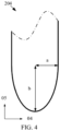
- FIG 4 is an enlarged schematic view of one of the ends 204 of the hole 202.
- each of the holes 202 may extend along the second direction 05.
- the symmetry axes 08 corresponding to the two semi-ellipses formed as the two end portions 204 may be parallel to the first direction 04.
- the minor axis a of the semi-ellipse is parallel to the first direction 04. It is understandable that, as shown in FIG 4 , the two opposite ends 204 in the projection are set to be semi-elliptical to prevent the end 204 from including sharp portions, which can further relieve stress.
- a semi-ellipse can avoid over-etching during the etching process to cause the size of the hole 202 to be too large, which is more convenient for the process.
- the projection of the hole 202 on the display layer 10 is a centrally symmetrical figure, as shown in Table 1, which is the value of some parameters in FIG 3 , where a is the minor axis of the semi-ellipse; b is the major axis of the semi-ellipse, x is the distance between two adjacent holes 202 in the second direction 05, y is the distance between two adjacent holes 202 in the first direction 04, L is the distance between centers of the ellipses in the two ends 204 of the same hole 202, L1 is the distance between the centers of two adjacent holes 202 in the second direction 05, and L2 is the distance between the centers of two adjacent holes 202 in the first direction 04.
- Table 1 is the value of some parameters in FIG 3 , where a is the minor axis of the semi-ellipse; b is the major axis of the semi-ellipse, x is the distance between two adjacent holes 202 in the second direction 05, y is the distance between two adjacent holes
- y may show a gradual change trend in the first direction 04.
- the size of y may be gradually set smaller in a direction away from the center of the projection, and x may have a gradually changing trend in the second direction 05.
- Tabel 1 parameter name a b x y L L1 L2 Size (mm) 0.1 0.2 0.16 to 2.5 0.114 to 0.271 1.9 to 4.24 4.8 0.314 to 0.471
- At least one hole 202 extends from a side of the composite portion 201 close to the display layer 10 to a side away from the display layer 10, and the hole 202 does not penetrate the composite portion 201. It is understandable that the hole 202 in this embodiment is formed on the side of the composite portion 201 close to the display layer 10, and is not present on the composite portion 201 away from the display layer 10. It is understandable that the user watches and touches from the side of the composite portion 201 away from the display layer 10. In this embodiment, by setting the position of the hole 202 reasonably, it is possible to avoid reducing the quality of the display and the texture of the touch.
- the material filled in the hole 202 includes resin or curing adhesive.
- the composite portion 201 may be made of glass or may be a film layer formed of aramid fiber, and the elastic modulus of the composite portion 201 may be in the order of gigapascals.
- the elastic modulus of the structure filled with resin or curing adhesive in the hole 202 can be 1 MPa to 100 MPa, and the tensile or compression resilience rate is not less than 99%. That is, the elastic modulus of the structure formed in the hole 202 is small, which can effectively improve the elastic performance of the composite portion 201 while achieving a higher hardness of the composite portion 201.
- the composite portion 201 with a thickness of 0.03mm to 0.7mm can be prepared by using glass.
- the hole 202 can be filled with optical grade resin or optical curing adhesive whose optical properties such as refractive index and transmittance are close to glass. Further, a liquid optical grade resin or optical curing adhesive may be used to fill the hole 202, and then be cured by high temperature or ultraviolet light irradiation to form a solid structure filled in the hole 202.
- the display layer 10 includes: an array substrate layer 101, wherein the array substrate layer 101 includes a plurality of film layers; and a light-emitting layer 102, wherein the light-emitting layer 102 is located on the array substrate layer 101, and the cover plate layer 20 is located on the light-emitting layer 102.
- At least one of the film layers of the array substrate layer 101 is provided with a plurality of first openings in the portion of the bending area 01. Further, the first openings may also be filled with a material having an elastic modulus smaller than that of the film layer. In the same way, this embodiment can make the part of the film layer located in the bending area 01 have higher flexibility and greater elasticity.
- the display layer 10 may also include: a metal layer 103; a flexible substrate layer 104 located between the metal layer 103 and the array substrate layer 101; and an encapsulation layer 105 on the side of the light-emitting layer 102 away from the array substrate layer 101.
- the permeability of the metal layer 103 may not be less than 1.5H/m.
- the flexible substrate layer 104 may be made of polyimide.
- the display screen 100 may also include: a touch layer 30 located on the display layer 10, and a polarizing layer 40 on the touch layer 30, wherein the cover plate layer 20 may be fixed on the polarizing layer 40 through an adhesive layer 50.
- a protective layer 60 may be provided on the cover plate layer 20.
- the adhesive layer 50 can be, but is not limited to, an optical resin or a curing adhesive.
- the constituent material of the protective layer 60 may be, but not limited to, a transparent polyimide film, or the protective layer 60 may be made of polyester resin or polyurethane.
- an adhesive layer may be provided between the protective layer 60 and the cover plate layer 20, and the adhesive layer may be made of silica gel or adhesive.
- the pull-out force between the adhesive layer and the cover plate layer 20 may range from 5g/25mm to 100g/25mm. It is understandable that when the protective layer 60 is damaged, the protective layer 60 can be removed, or even a new protective layer can be replaced to protect the cover plate layer 20.
- the present invention provides a display device, which includes but is not limited to the following embodiments and a combination of the following embodiments.
- the display device 200 includes a display screen 100.
- the display screen 100 includes: a display layer 10; and a cover plate layer 20, wherein the cover plate layer 20 is located on the display layer 10, and the cover plate layer 20 includes a composite portion 201 located in the bending area 01, wherein the composite portion 201 is provided with a plurality of holes, and the holes are filled with a material whose elastic modulus is less than an elastic modulus of the composite portion 201.
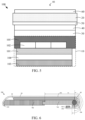
- the display device 200 further includes: a support member, wherein the display screen is laid on the support member, and the support member includes a first support member 701 and a second support member 702, as shown in FIG 7 , wherein the first support member 701 and the second support member 702 are relatively slidingly arranged, and the first support member 701 corresponds to the bending area 01; a transmission mechanism, wherein the transmission mechanism is connected to the first support member 701, as shown in FIG 6 , wherein the first end 205 of the cover plate layer 20 is connected to an end of the second support member 702 away from the first support member 701, and the second end 206 of the cover plate layer 20 is connected to the transmission mechanism; and a reel 80, wherein the reel 80 is located at an end of the first support member 701 away from the second support member 702.
- the cover plate layer 20 is under the action of the second support member 702 and the transmission mechanism, such that the display screen moves relatively on the support member, and the reel 80 is used to assist the relative movement of the display screen on the support member.
- the display layer 10 includes a pre-bending portion 106.
- the pre-bending portion 106 bypasses the reel 80 and extends to the side of the first support member 701 away from the cover plate layer 20.
- the pre-bending portion 106 is located at an end of the first support member 701 away from the cover plate layer 20 after the display screen 100 moves on the support member.
- the transmission mechanism includes two racks 901, two gear sets 904, two screws 902, and a slider 903 located on a back of the first support member 701.
- the two racks 901 are respectively located on opposite sides of the first support member 701.
- the two racks 901 are perpendicular to the reel 80.
- Each screw 902 is connected to the corresponding rack 901 through a gear set 904.
- the slider 903 is parallel to the reel 80.
- the two ends of the slider 903 are respectively connected to the two screws 902.
- the second end 206 of the cover plate layer 20 is connected to the slider 903. It should be noted that the slider 903 and the screw 902 may be located between the second end 206 of the cover plate layer 20 and the first support member 701, so as to facilitate the attachment and assembly of the cover plate layer 20 and the slider 903.
- the second support member 702 slides toward the first support member 701 through the rack 901 and the gear set 904.
- a first end 205 of the cover plate layer 20 also slides toward the first support member 701, causing the second end 206 of the cover plate layer 20 to slide toward the second support member 70, such that the display device 200 can change from the state of FIG 6 to the state of FIG 8 , and also drive the slider 903 to slide toward the second support member 702.
- the gear set 904 can also drive the slider 903 to slide toward the second support member 702 through the screw 902. Further, sliding the slider 903 toward the second support member 702 can make the second end 206 of the cover plate layer 20 slide toward the second support member 702. Finally, it helps to realize the state of FIG 6 to the state of FIG 8 .
- the second support member 702 slides away from the first support member 701 through the rack 901 and the gear set 904.
- the first end 205 of the cover plate layer 20 also slides away from the first support member 701, causing the second end 206 of the cover plate layer 20 to slide away from the second support member 702, such that the display device 200 can change from the state of FIG 8 to the state of FIG 6 , and also drive the slider 903 to slide in a direction away from the second support member 702.
- the gear set 904 can also be driven by the screw 902 to drive the slider 903 to slide in a direction away from the second support member 702.
- sliding the slider 903 in a direction away from the second support member 702 can make the second end 206 of the cover plate layer 20 slide in a direction away from the second support member 702. Finally, it helps to realize the state of FIG 8 to the state of FIG 6 .
- a plurality of holes are provided in the composite portion 201.
- the pre-bending portion 106 is set to bypass the reel 80 and extend to the side of the first support member 701 away from the cover plate layer 20. That is, in a cross-sectional perspective, as shown in FIG 6 , the pre-bending portion 106, which covers the half circle on the side of the reel 80 away from the second support member 702 and covers the size of the first support member 701 on the side away from the cover plate layer 20, is equal to the radius of the reel 80.
- the display layer 10 can follow the movement of the cover plate layer 20 as a whole. Therefore, there will be no step difference on the side of the display layer 10 close to the cover plate layer 20, and the display layer 10 will not be broken or glass due to uneven force. The curling performance and lifespan of the display device 200 are improved.
- the display layer 10 includes a polarizing layer 40. Two ends of the polarizing layer 40 are respectively connected to two ends of the cover plate layer 20. As shown in Figure 6 to Figure 8 , when the second support member 702 and the first support member 701 slide relatively, the cover plate layer 20 and the polarizing layer 40 are under the action of the second support member 702 and the transmission mechanism. This causes the display screen 100 to move relative to the support member.
- the two ends of the polarizing layer 40 are connected to the two ends of the cover plate layer 20, respectively. Therefore, the support member and the transmission mechanism can act on the cover plate layer 20 and the polarizing layer 40 at the same time. That is, the polarizing layer 40 can share the force exerted on the cover plate layer 20 by the support member and the transmission mechanism.
- the polarizing layer 40 and the cover plate layer 20 simultaneously serve as a force-receiving layer to increase the strength of the force-receiving layer. The risk of breaking when only the cover plate layer 20 is used as the stressed layer is avoided, and the life span of the display device 200 is improved.
- the display device 200 may further include a bottom shell 1001 and two side shells 1002.
- the bottom shell 1001 and the two side shells 1002 are used for accommodating the transmission mechanism and the display screen 100.
- the bottom shell 1001 extends from the side of the transmission mechanism away from the support member to the side of the reel 80 away from the support member.
- the two side shells 1002 are parallel to the rack 901 and connected to two opposite sides of the bottom shell 1001.
- An embodiment of the present invention provides a display screen and a display device.
- the display screen comprises a bending area, wherein the display screen comprises: a display layer; and a cover plate layer.
- the cover plate layer is located on the display layer, and the cover plate layer includes a composite portion located in the bending area, wherein a plurality of holes are defined in the composite portion, and the holes are filled with a material, and an elastic modulus of the material is smaller than an elastic modulus of the composite portion.
- a plurality of holes are opened in a part of the cover plate layer located in the bending area, and the holes are filled with a material with a smaller elastic modulus, so as to take into account hardness and elasticity of a part of the cover plate layer located in the bending area. Low hardness, poor abrasion resistance, and poor ball drop performance of this part is avoided, and the ability of the display screen to prevent damage is improved.
Landscapes
- Engineering & Computer Science (AREA)
- Theoretical Computer Science (AREA)
- Physics & Mathematics (AREA)
- General Physics & Mathematics (AREA)
- Computer Hardware Design (AREA)
- Human Computer Interaction (AREA)
- General Engineering & Computer Science (AREA)
- Microelectronics & Electronic Packaging (AREA)
- Mathematical Physics (AREA)
- Signal Processing (AREA)
- Devices For Indicating Variable Information By Combining Individual Elements (AREA)
Abstract
Description
- The present invention relates to displays, and in particular to a technical field of display panel manufacturing, in more particular to a display screen and a display device.
- Compared with traditional screens, flexible screens have the characteristics of bendable and foldable. A curling screen is a flexible screen that is based on the bendable characteristics of the flexible screen, and realizes the enlargement and reduction of the screen by shrinking and stretching the display screen.
- An outermost layer of the curling screen is generally made of polymer materials to achieve bending characteristics, resulting in lower hardness, poor abrasion resistance, and poor ball drop performance of the outermost layer of the curling screen, which reduces the ability of the curling screen to prevent damage.
- From above, it is necessary to provide a display screen and a display device that can improve an anti-damage ability of the screen.
- An object of the present invention is to provide a display screen and a display device, so as to solve problems in the prior art that the outermost layer of the display screen has low hardness, poor abrasion resistance, and poor ball-dropping performance, which results in a low damage prevention ability of the screen.
- An embodiment of the present invention provides a display screen comprising a bending area, wherein the display screen comprises:
- a display layer; and
- a cover plate layer, wherein the cover plate layer is located on the display layer, and the cover plate layer includes a composite portion located in the bending area, wherein a plurality of holes are defined in the composite portion, and the holes are filled with a material, and an elastic modulus of the material is smaller than an elastic modulus of the composite portion,
- wherein the display layer comprises an array substrate layer, the array substrate layer comprises a plurality of film layers, and a portion of at least one of the film layers in the array substrate layer is provided with a plurality of first openings.
- In an embodiment, the composite portion comprises a main composite portion and a first auxiliary composite portion and a second auxiliary composite portion located on both sides of the main composite portion, wherein a volume ratio of the plurality of holes in the main composite portion is greater than a volume ratio of the plurality of holes in any one of the first auxiliary composite portion and the second auxiliary composite portion.
- In an embodiment, a volume of the holes in the main composite portion is greater than a volume of the holes in any one of the first auxiliary composite portion and the second auxiliary composite portion.
- In an embodiment, a distance between two adjacent holes in the main composite portion is less than a distance between two adjacent holes in any one of the first auxiliary composite portion and the second auxiliary composite portion.
- In an embodiment, the plurality of holes are arranged into a plurality of hole groups, and each of the hole groups includes the plurality of holes,
wherein the plurality of hole groups are arranged along a first direction, the plurality of holes in every two adjacent hole groups are arranged staggered along a second direction, wherein the first direction is a direction in which the main composite portion points to the second auxiliary composite portion, and the first direction is perpendicular to the second direction. - In an embodiment, the plurality of holes in every two adjacent hole groups in the main composite portion have overlapping portions in the second direction.
- An embodiment of the present invention provides a display screen comprising a bending area, wherein the display screen comprises:
- a display layer; and
- a cover plate layer, wherein the cover plate layer is located on the display layer, and the cover plate layer includes a composite portion located in the bending area, wherein a plurality of holes are defined in the composite portion, and the holes are filled with a material, and an elastic modulus of the material is smaller than an elastic modulus of the composite portion.
- In an embodiment, the composite portion comprises a main composite portion and a first auxiliary composite portion and a second auxiliary composite portion located on both sides of the main composite portion, wherein a volume ratio of the plurality of holes in the main composite portion is greater than a volume ratio of the plurality of holes in any one of the first auxiliary composite portion and the second auxiliary composite portion.
- In an embodiment, a volume of the holes in the main composite portion is greater than a volume of the holes in any one of the first auxiliary composite portion and the second auxiliary composite portion.
- In an embodiment, a distance between two adjacent holes in the main composite portion is less than a distance between two adjacent holes in any one of the first auxiliary composite portion and the second auxiliary composite portion.
- In an embodiment, the plurality of holes are arranged into a plurality of hole groups, and each of the hole groups includes the plurality of holes,
wherein the plurality of hole groups are arranged along a first direction, the plurality of holes in every two adjacent hole groups are arranged staggered along a second direction, wherein the first direction is a direction in which the main composite portion points to the second auxiliary composite portion, and the first direction is perpendicular to the second direction. - In an embodiment, the plurality of holes in every two adjacent hole groups in the main composite portion have overlapping portions in the second direction.
- In an embodiment, the plurality of holes in the two adjacent hole groups in the first auxiliary composite portion and the second auxiliary composite portion have overlapping portions in the second direction, wherein, in the second direction, a size of the overlapping portions of the first auxiliary composite portion and the second auxiliary composite portion is smaller than a size of the overlapping portions in the main composite portion.
- In an embodiment, in the first direction, a plurality of first gaps are defined between two adjacent holes in the first auxiliary composite portion, and the plurality of the first gaps show a decreasing trend in the first direction.
- In an embodiment, in the first direction, a plurality of second gaps are defined between two adjacent holes in the second auxiliary composite portion, and a plurality of the second gaps show an increasing trend in the first direction.
- In an embodiment, a projection of the holes on the display layer is an axisymmetric figure, and two opposite ends in the projection are both semi-elliptical, wherein extension lines of major axes of two semi-ellipses are both perpendicular to a symmetry axis of the projection.
- In an embodiment, at least one of the holes extends from a side of the composite portion close to the display layer to a side away from the display layer, and the holes do not penetrate the composite portion.
- In an embodiment, material filled in the holes comprises resin or curing adhesive.
- An embodiment of the present invention provides a display device comprising a display screen, wherein the display screen comprises:
- a display layer;
- a cover plate layer, wherein the cover plate layer is located on the display layer, and the cover plate layer includes a composite portion located in a bending area, wherein a plurality of holes are defined in the composite portion, and the holes are filled with a material, and an elastic modulus of the material is smaller than an elastic modulus of the composite portion,
- wherein the display device further comprises:
- a support member, wherein the display screen is laid on the support member, and the support member comprises a first support member and a second support member, wherein the first support member and the second support member are relatively slidably arranged, and the first support member corresponds to the bending area;
- a transmission mechanism, wherein the transmission mechanism is connected to the first support member, a first end of the cover plate layer is connected to an end of the second support member away from the first support member, and a second end of the cover plate layer is connected to the transmission mechanism; and
- a reel, wherein the reel is located at an end of the first support member away from the second support member,
- wherein, when the second support member and the first support member slide relatively, the cover plate layer causes the display screen to move relative to the support member under an action of the second support member and the transmission mechanism, wherein the reel is used to assist a relative movement of the display screen on the support member; and
- wherein the display layer comprises a pre-bending portion, the pre-bending portion bypasses the reel and extends to a side of the first support member away from the cover plate layer, or the pre-bending portion is located at an end of the first support member away from the cover plate layer after the display screen moves relative to the support member.
- In an embodiment, the display layer comprises a polarizing layer, and two ends of the polarizing layer are respectively connected to two ends of the cover plate layer,
wherein, when the second support member and the first support member slide relatively, the cover plate layer and the polarizing layer make the display screen relatively move on the support member under an action of the second support member and the transmission mechanism. - An embodiment of the present invention provides a display screen and a display device. The display screen comprises a bending area, wherein the display screen comprises: a display layer; and a cover plate layer. The cover plate layer is located on the display layer, and the cover plate layer includes a composite portion located in the bending area, wherein a plurality of holes are defined in the composite portion, and the holes are filled with a material, and an elastic modulus of the material is smaller than an elastic modulus of the composite portion. In this solution, a plurality of holes are opened in a part of the cover plate layer located in the bending area, and the holes are filled with a material with a smaller elastic modulus, so as to take into account hardness and elasticity of a part of the cover plate layer located in the bending area. Low hardness, poor abrasion resistance, and poor ball drop performance of this part is avoided, and the ability of the display screen to prevent damage is improved.
- The technical solutions and other beneficial effects of the present application will be made obvious by describing the specific implementation manners of the present application in detail below in conjunction with the accompanying drawings.
-
FIG 1 is a schematic cross-sectional view of a display screen provided by the present invention; -
FIG 2 is a schematic top view of a composite portion provided by the present invention; -
FIG 3 is a schematic top view of a part of the holes in the composite portion provided by the present invention; -
FIG 4 is a schematic diagram of an enlarged end of a projection of the holes provided by the present invention; -
FIG 5 is a schematic cross-sectional view of another display screen provided by the present invention; -
FIG 6 is a schematic cross-sectional view of the display device in a first state provided by the present invention; -
FIG 7 is an exploded schematic diagram of the display device provided by the present invention; and -
FIG 8 is a schematic cross-sectional view of the display device in a second state provided by the present invention. - The technical solutions in the embodiments of the present invention will be clearly and completely described below in conjunction with the drawings in the embodiments of the present invention. Obviously, the described embodiments are only a part of the embodiments of the present invention, rather than all the embodiments. Based on the embodiments in this invention, all other embodiments obtained by those skilled in the art without creative work shall fall within the protection scope of this invention. Mentioning "embodiments" herein means that a specific feature, structure, or characteristic described in conjunction with the embodiments may be included in at least one embodiment of the present invention. The appearance of the phrase in various places in the specification does not necessarily refer to the same embodiment, nor is it an independent or alternative embodiment mutually exclusive with other embodiments. Those skilled in the art clearly and implicitly understand that the embodiments described herein can be combined with other embodiments. In addition, it should be noted that the drawings only provide structures that are closely related to the invention, and some details that are not relevant to the invention are omitted. The purpose is to simplify the drawings so that the invention points are clear at a glance, instead of showing that the actual device is exactly the same as the drawings, and is not a limitation of the actual device.
- The present invention provides a display screen, which includes but is not limited to the following embodiments and a combination of the following embodiments.
- In an embodiment, as shown in
FIG 1 , thedisplay screen 100 includes a bendingarea 01. The display screen includes: adisplay layer 10; acover plate layer 20. Thecover plate layer 20 is located on thedisplay layer 10. Thecover plate layer 20 includes acomposite portion 201 located in the bendingarea 01. As shown inFIG 2 , a plurality ofholes 202 are provided in thecomposite portion 201. Theholes 202 are filled with a material, wherein an elastic modulus of the material is smaller than an elastic modulus of thecomposite portion 201. - The
display screen 100 can be applied to a cloud curl display device or other flexible display devices. Specifically, when thedisplay screen 100 is applied to a cloud curl display device, the bendingarea 01 can be understood as a part of thedisplay screen 100 that can be located on a front or back of the cloud curl display device through a curling motion. That is, the bendingarea 01 needs to perform a long-term crimping movement, so the bendingarea 01 needs to have higher flexibility and greater elasticity. - It is understandable that, as shown in
FIG 1 , thecover plate layer 20 is located on thedisplay layer 10. Further, thecover plate layer 20 may extend beyond thedisplay layer 10 to be connected to other components of the cloud curl display device. Specifically, thedisplay layer 10 may be located between other components of the cloud curl display device and thecover plate layer 20. Other components of the cloud curl display device drive thecover plate layer 20 to perform a curling movement, thereby driving thedisplay layer 10 to perform a curling movement. Therefore, thecomposite portion 201 also needs to perform a long-term crimping movement, so thecomposite portion 201 needs to have higher flexibility and greater elasticity. It should be noted that in this embodiment, the plurality ofholes 202 are opened in thecomposite portion 201, and theholes 202 are filled with a material whose elastic modulus is smaller than that of thecomposite portion 201. This ensures higher flexibility and greater elasticity of thecomposite portion 201. At the same time, this embodiment does not use a same material with a smaller elastic modulus to make thecomposite portion 201. Instead, the elastic modulus of thecomposite portion 201 is set to be greater than the elastic modulus of the material filled in thehole 202, so that thecomposite portion 201 can still have suitable hardness and abrasion resistance, which improves the ability of the display screen to prevent damage. - In an embodiment, as shown in
FIG 2 , thecomposite portion 201 includes a maincomposite portion 2011 and a first auxiliarycomposite portion 2012 and a second auxiliarycomposite portion 2013 located on both sides of the maincomposite portion 2011. A volume ratio of the plurality ofholes 202 in the maincomposite portion 2011 is larger than a volume ratio of the plurality ofholes 202 in any one of the first auxiliarycomposite portion 2012 and the second auxiliarycomposite portion 2013. - Specifically, as shown in
FIG 1 , thedisplay screen 100 further includes twonon-bending areas 02, and both of thenon-bending areas 02 can be arranged adjacent to the bendingarea 01. Further, the twonon-bending areas 02 may be located on opposite sides of the bendingarea 01, respectively. It can be seen fromFIG 2 that the first auxiliarycomposite portion 2012 may be disposed close to one of thenon-bending regions 02. The second auxiliarycomposite portion 2013 may be arranged close to the othernon-bending area 02. It is understandable that since the twonon-bending areas 02 do not need to perform a curling movement, the twonon-bending areas 02 do not need to have higher flexibility and greater elasticity. Conversely, greater stiffness may be required to support thedisplay screen 100. - According to the above discussion, an overall flexibility or hardness setting of the
cover plate layer 20 may be consistent with the overall flexibility or hardness setting of thedisplay screen 100. It should be noted that whether the plurality ofholes 202 are opened in thecomposite portion 201, or theholes 202 are filled with a material whose elastic modulus is smaller than that of thecomposite portion 201, compared with the part of thecover plate layer 20 where thehole 202 is not provided, the hardness will be reduced. It is understandable that in this embodiment, a volume ratio of the plurality ofholes 202 in the maincomposite portion 2011 is set to be greater than a volume ratio of the plurality ofholes 202 in any one of the first auxiliarycomposite portion 2012 and the second auxiliarycomposite portion 2013. Therefore, the volume ratio of the plurality ofholes 202 in the first auxiliarycomposite portion 2012 and the volume ratio of the plurality ofholes 202 in the second auxiliarycomposite portion 2013 are both smaller than the volume ratio of the plurality ofholes 202 in the maincomposite portion 2011. That is, a hardness of the first auxiliarycomposite portion 2012 and the hardness of the second auxiliarycomposite portion 2013 are both greater than the hardness of the maincomposite portion 2011, and a hardness of the first auxiliarycomposite portion 2012 and the hardness of the second auxiliarycomposite portion 2013 are also significantly smaller than a hardness of the two parts on both sides of thecomposite portion 201. Therefore, the first auxiliarycomposite portion 2012 and the second auxiliarycomposite portion 2013 are equivalent to forming a "hardness transition area" in the bendingarea 01 close to the twonon-bending areas 02. The "hardness transition area" can prevent the hardness difference between the bendingarea 01 and any one of thenon-bending areas 02 from being too large, and the force difference during crimping may cause fracture. - In one embodiment, as shown in
FIG 2 , a volume of thehole 202 in the maincomposite portion 2011 is greater than the volume of the hole in any one of the first auxiliarycomposite portion 2012 and the second auxiliarycomposite portion 2013. The volume of theholes 202 can be understood as the volume of the solid matter when theholes 202 are filled with solid matter. The shape of theholes 202 is not limited here. - According to the above discussion, a hardness of the
composite portion 201 is negatively correlated with a total volume of the plurality ofholes 202 in thecomposite portion 201 or a total volume of themultiple holes 202 filled with materials whose elastic modulus is smaller than thecomposite portion 201. Specifically, in this embodiment, the volume of thehole 202 in the maincomposite portion 2011 is set to be greater than any of the first auxiliarycomposite portion 2012 and the second auxiliarycomposite portion 2013. State the volume of thehole 202. The volume of the plurality ofholes 202 in different areas of thecomposite portion 201 can be set reasonably, so as to realize that a volume ratio of the plurality ofholes 202 in the maincomposite portion 2011 is greater than a volume ratio of the plurality ofholes 202 in any one of the first auxiliarycomposite portion 2012 and the second auxiliarycomposite portion 2013. Further, as shown inFIG 2 , for the entirecomposite portion 201, in the direction from thesymmetry axis 03 of thecomposite portion 201 to thenon-bending area 02, the volume of the plurality ofholes 202 can be gradually reduced to gradually increase the hardness. Therefore, the "hardness transition area" is formed, so as to avoid that the hardness difference between the bendingarea 01 and any one of thenon-bending areas 02 is too large, and the force difference during crimping is too large to cause breakage. Asymmetry axis 03 may be parallel to a boundary line between the bendingarea 01 and thenon-bending area 02. - In one embodiment, as shown in
FIG 2 , a distance between twoadjacent holes 202 in the maincomposite portion 2011 is less than a distance between twoadjacent holes 202 in any one of the first auxiliarycomposite portion 2012 and the second auxiliarycomposite portion 2013. The distance between twoadjacent holes 202 can be understood as an average value of the distance between every twoadjacent holes 202. A relative positional relationship of the plurality ofholes 202 is not limited here. - According to the above discussion, the hardness of the
composite portion 201 is negatively correlated with a total volume of the plurality ofholes 202 of thecomposite portion 201 or a total volume of the plurality ofholes 202 of thecomposite portion 201 filled with a material having an elastic modulus less than the elastic modulus of thecomposite portion 201. Specifically, in this embodiment, the distance between twoadjacent holes 202 in the maincomposite portion 2011 is set to be less than a distance between twoadjacent holes 202 in any one of the first auxiliarycomposite portion 2012 and the second auxiliarycomposite portion 2013. The arrangement gaps of the plurality ofholes 202 in different areas of thecomposite portion 201 can be reasonably set, so as to realize that the volume ratio of the plurality ofholes 202 in the maincomposite portion 2011 is greater than the volume ratio of the plurality ofholes 202 in any one of the first auxiliarycomposite portion 2012 and the second auxiliarycomposite portion 2013. Further, as shown inFIG 2 , for the entirecomposite portion 201, in the direction from thesymmetry axis 03 of thecomposite portion 201 to thenon-bending area 02, a gap between twoadjacent holes 202 can be gradually increased to gradually increase the hardness. Therefore, the "hardness transition area" is formed, so as to avoid that the hardness difference between the bendingarea 01 and any one of thenon-bending areas 02 is too large, and the force difference during crimping is too large to cause breakage. - In an embodiment, as shown in
FIG 2 , the plurality ofholes 202 are arranged into a plurality ofhole groups 203. Eachhole group 203 includes a plurality ofholes 202, wherein a plurality of saidhole groups 203 are arranged along thefirst direction 04. The plurality ofholes 202 in every twoadjacent hole groups 203 are arranged staggered along thesecond direction 05. Thefirst direction 04 is the direction in which the maincomposite portion 2011 points to the second auxiliarycomposite portion 2013. Thefirst direction 04 is perpendicular to thesecond direction 05. - For ease of description here, it can be considered that each of the
hole groups 203 extends in a row along thesecond direction 05. The plurality ofholes 202 arranged along thefirst direction 04 in the plurality ofhole groups 203 are formed in a row. Specifically, the plurality ofholes 202 in every twoadjacent hole groups 203 are arranged and staggered along thesecond direction 05. It can be understood that the plurality ofholes 202 located in any two adjacent columns are arranged staggered in thesecond direction 05. That is, left and right sides of one of theholes 202 are set as gaps, so it can be understood that the plurality ofholes 202 in the odd-numbered columns can be arranged in odd-numbered rows such as a first row, a third row, and a fifth row. Correspondingly, the plurality ofholes 202 located in even-numbered columns can be arranged in even-numbered rows such as a second row, a fourth row, and a sixth row. That is, the plurality ofholes 202 may be arranged in an array along thefirst direction 04 and thesecond direction 05. It can be understood that, at the same time, the plurality ofholes 202 located in any two rows may also be arranged in a staggered arrangement along thefirst direction 04. - In an embodiment, as shown in
FIG 2 , each of the plurality ofholes 202 in the twoadjacent hole groups 203 in the maincomposite portion 2011 has an overlapping portion in thesecond direction 05. Specifically, as shown inFIG 2 , for the plurality ofholes 202 in the maincomposite portion 2011, in the case where one of theholes 202 corresponds to a gap in theadjacent hole group 203, thehole 202 may extend beyond the corresponding gap in thesecond direction 05, so as to overlap thehole 202 on the upper side and thehole 202 on the lower side of the corresponding gap. In combination with the above discussion, it can also be understood that the plurality ofholes 202 located in two adjacent rows in the maincomposite portion 2011 have overlapping portions in thesecond direction 05. A size of the overlapping portions in thesecond direction 05 is not limited, which is only necessary to ensure that there is still a corresponding gap between twoadjacent holes 202 in eachhole group 203. It is understandable that the arrangement of the overlapping portion in this embodiment can further increase the arrangement density of the plurality ofholes 202 in the maincomposite portion 2011. Therefore, the maincomposite portion 2011 has higher flexibility and greater elasticity. - In one embodiment, as shown in
FIG 2 , the plurality ofholes 202 in the twoadjacent hole groups 203 in the first auxiliarycomposite portion 2012 and the second auxiliarycomposite portion 2013 have overlapping portions in thesecond direction 05. In thesecond direction 05, a size of the overlapping portion of the first auxiliarycomposite portion 2012 and the second auxiliarycomposite portion 2013 is smaller than a size of the overlapping portion in the maincomposite portion 2011. According to the above discussion, first of all, in this embodiment, the overlapping portion is provided in both the first auxiliarycomposite portion 2012 and the second auxiliarycomposite portion 2013. The flexibility and elasticity of the first auxiliarycomposite portion 2012 and the second auxiliarycomposite portion 2013 can be appropriately improved. Secondly, the size of the overlapping portion of the first auxiliarycomposite portion 2012 and the second auxiliarycomposite portion 2013 is set to be smaller than the size of the overlapping portion of the maincomposite portion 2011. Therefore, the hardness of the first auxiliarycomposite portion 2012 and the second auxiliarycomposite portion 2013 can still be greater than the hardness of the maincomposite portion 2011 to form the "hardness transition area". - In an embodiment, as shown in
FIG 2 , in thefirst direction 04, there is afirst gap 06 between twoadjacent holes 202 in the first auxiliarycomposite portion 2012, and a plurality of thefirst gaps 06 show a decreasing trend in thefirst direction 04. Specifically, the more theholes 202 in the first auxiliarycomposite portion 2012 are closer to the maincomposite portion 2011, the closer they are arranged, such that the closer the first auxiliarycomposite portion 2012 is to the maincomposite portion 2011, the smaller the hardness. The more theholes 202 in the first auxiliarycomposite portion 2012 are farther away from the maincomposite portion 2011, the more sparsely they are arranged, such that the farther the first auxiliarycomposite portion 2012 is, the greater the hardness of the part of the maincomposite portion 2011 is. In the same way, the "hardness transition area" is formed to prevent the hardness difference between the bendingarea 01 and any one of thenon-bending area 02 from being too large and the force difference during crimping may cause fracture. - In one embodiment, as shown in
FIG 2 , in thefirst direction 04, there is asecond gap 07 between twoadjacent holes 202 in the second auxiliarycomposite portion 2013, the plurality ofsecond gaps 07 show an increasing trend in thefirst direction 04. Specifically, the more theholes 202 in the second auxiliarycomposite portion 2013 are closer to the maincomposite portion 2011, the closer they are arranged, such that the closer the first auxiliarycomposite portion 2012 is to the maincomposite portion 2011, the smaller the hardness. The more theholes 202 in the second auxiliarycomposite portion 2013 are farther away from the maincomposite portion 2011, the more sparsely they are arranged, such that the farther the first auxiliarycomposite portion 2012 is, the greater the hardness of the part of the maincomposite portion 2011 is. In the same way, the "hardness transition area" is formed to prevent the hardness difference between the bendingarea 01 and any one of thenon-bending areas 02 from being too large and the force difference during crimping may cause fracture. - In one embodiment, as shown in
FIGS. 2 to 4 , a projection of theholes 202 on thedisplay layer 10 is an axisymmetric figure, and the opposite ends 204 in the projection are both semi-elliptical. The major axes b of the two semi-ellipses are both perpendicular to thesymmetry axis 08 of the projection. Specifically, the shape of the plurality ofholes 202 may be the same, as shown inFIGS. 2 to 4 .FIG 3 is a schematic diagram of the arrangement of some of theholes 202 inFIG 2 , andFIG 4 is an enlarged schematic view of one of theends 204 of thehole 202. Further, each of theholes 202 may extend along thesecond direction 05. That is, the symmetry axes 08 corresponding to the two semi-ellipses formed as the twoend portions 204 may be parallel to thefirst direction 04. The minor axis a of the semi-ellipse is parallel to thefirst direction 04. It is understandable that, as shown inFIG 4 , the twoopposite ends 204 in the projection are set to be semi-elliptical to prevent theend 204 from including sharp portions, which can further relieve stress. In addition, compared to a semicircle, a semi-ellipse can avoid over-etching during the etching process to cause the size of thehole 202 to be too large, which is more convenient for the process. - Specifically, the projection of the
hole 202 on thedisplay layer 10 is a centrally symmetrical figure, as shown in Table 1, which is the value of some parameters inFIG 3 , where a is the minor axis of the semi-ellipse; b is the major axis of the semi-ellipse, x is the distance between twoadjacent holes 202 in thesecond direction 05, y is the distance between twoadjacent holes 202 in thefirst direction 04, L is the distance between centers of the ellipses in the two ends 204 of thesame hole 202, L1 is the distance between the centers of twoadjacent holes 202 in thesecond direction 05, and L2 is the distance between the centers of twoadjacent holes 202 in thefirst direction 04. Further, y may show a gradual change trend in thefirst direction 04. Specifically, the size of y may be gradually set smaller in a direction away from the center of the projection, and x may have a gradually changing trend in thesecond direction 05. For details, please refer to the relevant discussion above.Tabel 1: parameter name a b x y L L1 L2 Size (mm) 0.1 0.2 0.16 to 2.5 0.114 to 0.271 1.9 to 4.24 4.8 0.314 to 0.471 - In one embodiment, as shown in
FIG 1 and FIG 2 , at least onehole 202 extends from a side of thecomposite portion 201 close to thedisplay layer 10 to a side away from thedisplay layer 10, and thehole 202 does not penetrate thecomposite portion 201. It is understandable that thehole 202 in this embodiment is formed on the side of thecomposite portion 201 close to thedisplay layer 10, and is not present on thecomposite portion 201 away from thedisplay layer 10. It is understandable that the user watches and touches from the side of thecomposite portion 201 away from thedisplay layer 10. In this embodiment, by setting the position of thehole 202 reasonably, it is possible to avoid reducing the quality of the display and the texture of the touch. - In an embodiment, the material filled in the
hole 202 includes resin or curing adhesive. It should be noted that thecomposite portion 201 may be made of glass or may be a film layer formed of aramid fiber, and the elastic modulus of thecomposite portion 201 may be in the order of gigapascals. The elastic modulus of the structure filled with resin or curing adhesive in thehole 202 can be 1 MPa to 100 MPa, and the tensile or compression resilience rate is not less than 99%. That is, the elastic modulus of the structure formed in thehole 202 is small, which can effectively improve the elastic performance of thecomposite portion 201 while achieving a higher hardness of thecomposite portion 201. Thecomposite portion 201 with a thickness of 0.03mm to 0.7mm can be prepared by using glass. Further, thehole 202 can be filled with optical grade resin or optical curing adhesive whose optical properties such as refractive index and transmittance are close to glass. Further, a liquid optical grade resin or optical curing adhesive may be used to fill thehole 202, and then be cured by high temperature or ultraviolet light irradiation to form a solid structure filled in thehole 202. - In one embodiment, as shown in
FIG 5 , thedisplay layer 10 includes: anarray substrate layer 101, wherein thearray substrate layer 101 includes a plurality of film layers; and a light-emittinglayer 102, wherein the light-emittinglayer 102 is located on thearray substrate layer 101, and thecover plate layer 20 is located on the light-emittinglayer 102. At least one of the film layers of thearray substrate layer 101 is provided with a plurality of first openings in the portion of the bendingarea 01. Further, the first openings may also be filled with a material having an elastic modulus smaller than that of the film layer. In the same way, this embodiment can make the part of the film layer located in the bendingarea 01 have higher flexibility and greater elasticity. - Specifically, as shown in
FIG 5 , thedisplay layer 10 may also include: ametal layer 103; aflexible substrate layer 104 located between themetal layer 103 and thearray substrate layer 101; and anencapsulation layer 105 on the side of the light-emittinglayer 102 away from thearray substrate layer 101. The permeability of themetal layer 103 may not be less than 1.5H/m. Theflexible substrate layer 104 may be made of polyimide. Thedisplay screen 100 may also include: atouch layer 30 located on thedisplay layer 10, and apolarizing layer 40 on thetouch layer 30, wherein thecover plate layer 20 may be fixed on thepolarizing layer 40 through anadhesive layer 50. Aprotective layer 60 may be provided on thecover plate layer 20. Theadhesive layer 50 can be, but is not limited to, an optical resin or a curing adhesive. The constituent material of theprotective layer 60 may be, but not limited to, a transparent polyimide film, or theprotective layer 60 may be made of polyester resin or polyurethane. Further, an adhesive layer may be provided between theprotective layer 60 and thecover plate layer 20, and the adhesive layer may be made of silica gel or adhesive. The pull-out force between the adhesive layer and thecover plate layer 20 may range from 5g/25mm to 100g/25mm. It is understandable that when theprotective layer 60 is damaged, theprotective layer 60 can be removed, or even a new protective layer can be replaced to protect thecover plate layer 20. - The present invention provides a display device, which includes but is not limited to the following embodiments and a combination of the following embodiments.
- In an embodiment, as shown in
FIGS. 6 and7 , thedisplay device 200 includes adisplay screen 100. Thedisplay screen 100 includes: adisplay layer 10; and acover plate layer 20, wherein thecover plate layer 20 is located on thedisplay layer 10, and thecover plate layer 20 includes acomposite portion 201 located in the bendingarea 01, wherein thecomposite portion 201 is provided with a plurality of holes, and the holes are filled with a material whose elastic modulus is less than an elastic modulus of thecomposite portion 201. Thedisplay device 200 further includes: a support member, wherein the display screen is laid on the support member, and the support member includes afirst support member 701 and asecond support member 702, as shown inFIG 7 , wherein thefirst support member 701 and thesecond support member 702 are relatively slidingly arranged, and thefirst support member 701 corresponds to the bendingarea 01; a transmission mechanism, wherein the transmission mechanism is connected to thefirst support member 701, as shown inFIG 6 , wherein thefirst end 205 of thecover plate layer 20 is connected to an end of thesecond support member 702 away from thefirst support member 701, and thesecond end 206 of thecover plate layer 20 is connected to the transmission mechanism; and areel 80, wherein thereel 80 is located at an end of thefirst support member 701 away from thesecond support member 702. When thesecond support member 702 and thefirst support member 701 slide relatively, thecover plate layer 20 is under the action of thesecond support member 702 and the transmission mechanism, such that the display screen moves relatively on the support member, and thereel 80 is used to assist the relative movement of the display screen on the support member. As shown inFIG 6 , thedisplay layer 10 includes apre-bending portion 106. Thepre-bending portion 106 bypasses thereel 80 and extends to the side of thefirst support member 701 away from thecover plate layer 20. Or, as shown inFIG 8 , thepre-bending portion 106 is located at an end of thefirst support member 701 away from thecover plate layer 20 after thedisplay screen 100 moves on the support member. - As shown in
FIG 6 to FIG 8 , the transmission mechanism includes tworacks 901, two gear sets 904, twoscrews 902, and aslider 903 located on a back of thefirst support member 701. The tworacks 901 are respectively located on opposite sides of thefirst support member 701. The tworacks 901 are perpendicular to thereel 80. Eachscrew 902 is connected to thecorresponding rack 901 through agear set 904. Theslider 903 is parallel to thereel 80. The two ends of theslider 903 are respectively connected to the twoscrews 902. Further, thesecond end 206 of thecover plate layer 20 is connected to theslider 903. It should be noted that theslider 903 and thescrew 902 may be located between thesecond end 206 of thecover plate layer 20 and thefirst support member 701, so as to facilitate the attachment and assembly of thecover plate layer 20 and theslider 903. - Specifically, as shown in
FIG 6 andFIG 7 , thesecond support member 702 slides toward thefirst support member 701 through therack 901 and the gear set 904. In one aspect, afirst end 205 of thecover plate layer 20 also slides toward thefirst support member 701, causing thesecond end 206 of thecover plate layer 20 to slide toward the second support member 70, such that thedisplay device 200 can change from the state ofFIG 6 to the state ofFIG 8 , and also drive theslider 903 to slide toward thesecond support member 702. In another aspect, the gear set 904 can also drive theslider 903 to slide toward thesecond support member 702 through thescrew 902. Further, sliding theslider 903 toward thesecond support member 702 can make thesecond end 206 of thecover plate layer 20 slide toward thesecond support member 702. Finally, it helps to realize the state ofFIG 6 to the state ofFIG 8 . - Similarly, as shown in
FIGS. 8 and 7 , thesecond support member 702 slides away from thefirst support member 701 through therack 901 and the gear set 904. In one aspect, thefirst end 205 of thecover plate layer 20 also slides away from thefirst support member 701, causing thesecond end 206 of thecover plate layer 20 to slide away from thesecond support member 702, such that thedisplay device 200 can change from the state ofFIG 8 to the state ofFIG 6 , and also drive theslider 903 to slide in a direction away from thesecond support member 702. In another aspect, the gear set 904 can also be driven by thescrew 902 to drive theslider 903 to slide in a direction away from thesecond support member 702. Further, sliding theslider 903 in a direction away from thesecond support member 702 can make thesecond end 206 of thecover plate layer 20 slide in a direction away from thesecond support member 702. Finally, it helps to realize the state ofFIG 8 to the state ofFIG 6 . - It can be understood that in this embodiment, a plurality of holes are provided in the
composite portion 201. On the basis that the hole is filled with a material whose elastic modulus is smaller than the elastic modulus of thecomposite portion 201, thepre-bending portion 106 is set to bypass thereel 80 and extend to the side of thefirst support member 701 away from thecover plate layer 20. That is, in a cross-sectional perspective, as shown inFIG 6 , thepre-bending portion 106, which covers the half circle on the side of thereel 80 away from thesecond support member 702 and covers the size of thefirst support member 701 on the side away from thecover plate layer 20, is equal to the radius of thereel 80. In this way, when thesecond support member 702 and thefirst support member 701 are relatively sliding during the whole process, thedisplay layer 10 can follow the movement of thecover plate layer 20 as a whole. Therefore, there will be no step difference on the side of thedisplay layer 10 close to thecover plate layer 20, and thedisplay layer 10 will not be broken or glass due to uneven force. The curling performance and lifespan of thedisplay device 200 are improved. - In one embodiment, as shown in
FIG 5 , thedisplay layer 10 includes apolarizing layer 40. Two ends of thepolarizing layer 40 are respectively connected to two ends of thecover plate layer 20. As shown inFigure 6 to Figure 8 , when thesecond support member 702 and thefirst support member 701 slide relatively, thecover plate layer 20 and thepolarizing layer 40 are under the action of thesecond support member 702 and the transmission mechanism. This causes thedisplay screen 100 to move relative to the support member. - It can be understood that, combined with the above discussion, in this embodiment, the two ends of the
polarizing layer 40 are connected to the two ends of thecover plate layer 20, respectively. Therefore, the support member and the transmission mechanism can act on thecover plate layer 20 and thepolarizing layer 40 at the same time. That is, thepolarizing layer 40 can share the force exerted on thecover plate layer 20 by the support member and the transmission mechanism. Thepolarizing layer 40 and thecover plate layer 20 simultaneously serve as a force-receiving layer to increase the strength of the force-receiving layer. The risk of breaking when only thecover plate layer 20 is used as the stressed layer is avoided, and the life span of thedisplay device 200 is improved. - Further, as shown in
FIG 7 , thedisplay device 200 may further include abottom shell 1001 and twoside shells 1002. Thebottom shell 1001 and the twoside shells 1002 are used for accommodating the transmission mechanism and thedisplay screen 100. Thebottom shell 1001 extends from the side of the transmission mechanism away from the support member to the side of thereel 80 away from the support member. The twoside shells 1002 are parallel to therack 901 and connected to two opposite sides of thebottom shell 1001. - An embodiment of the present invention provides a display screen and a display device. The display screen comprises a bending area, wherein the display screen comprises: a display layer; and a cover plate layer. The cover plate layer is located on the display layer, and the cover plate layer includes a composite portion located in the bending area, wherein a plurality of holes are defined in the composite portion, and the holes are filled with a material, and an elastic modulus of the material is smaller than an elastic modulus of the composite portion. In this solution, a plurality of holes are opened in a part of the cover plate layer located in the bending area, and the holes are filled with a material with a smaller elastic modulus, so as to take into account hardness and elasticity of a part of the cover plate layer located in the bending area. Low hardness, poor abrasion resistance, and poor ball drop performance of this part is avoided, and the ability of the display screen to prevent damage is improved.
- The display screen and the display device provided by the embodiments of the present invention are described in detail above. Specific examples are used in this article to illustrate the principle and implementation of the present invention. The description of the above embodiments is only used to help understand the technical solutions and core ideas of the present invention. Those of ordinary skill in the art should understand that: they can still modify the technical solutions described in the foregoing embodiments, or equivalently replace some of the technical features. However, these modifications or replacements do not cause the essence of the corresponding technical solutions to deviate from the scope of the technical solutions of the embodiments of the present invention.
Claims (20)
- A display screen, comprising a bending area, wherein the display screen comprises:a display layer; anda cover plate layer, wherein the cover plate layer is located on the display layer, and the cover plate layer includes a composite portion located in the bending area, wherein a plurality of holes are defined in the composite portion, and the holes are filled with a material, and an elastic modulus of the material is smaller than an elastic modulus of the composite portion,wherein the display layer comprises an array substrate layer, the array substrate layer comprises a plurality of film layers, and a portion of at least one of the film layers in the array substrate layer is provided with a plurality of first openings.
- The display screen according to Claim 1, wherein the composite portion comprises a main composite portion and a first auxiliary composite portion and a second auxiliary composite portion located on both sides of the main composite portion, wherein a volume ratio of the plurality of holes in the main composite portion is greater than a volume ratio of the plurality of holes in any one of the first auxiliary composite portion and the second auxiliary composite portion.
- The display screen according to Claim 2, wherein a volume of the holes in the main composite portion is greater than a volume of the holes in any one of the first auxiliary composite portion and the second auxiliary composite portion.
- The display screen according to Claim 2, wherein a distance between two adjacent holes in the main composite portion is less than a distance between two adjacent holes in any one of the first auxiliary composite portion and the second auxiliary composite portion.
- The display screen according to Claim 2, wherein the plurality of holes are arranged into a plurality of hole groups, and each of the hole groups includes the plurality of holes,
wherein the plurality of hole groups are arranged along a first direction, the plurality of holes in every two adjacent hole groups are arranged staggered along a second direction, wherein the first direction is a direction in which the main composite portion points to the second auxiliary composite portion, and the first direction is perpendicular to the second direction. - The display screen according to Claim 5, wherein the plurality of holes in every two adjacent hole groups in the main composite portion have overlapping portions in the second direction.
- A display screen, comprising a bending area, wherein the display screen comprises:a display layer; anda cover plate layer, wherein the cover plate layer is located on the display layer, and the cover plate layer includes a composite portion located in the bending area, wherein a plurality of holes are defined in the composite portion, and the holes are filled with a material, and an elastic modulus of the material is smaller than an elastic modulus of the composite portion.
- The display screen according to Claim 7, wherein the composite portion comprises a main composite portion and a first auxiliary composite portion and a second auxiliary composite portion located on both sides of the main composite portion, wherein a volume ratio of the plurality of holes in the main composite portion is greater than a volume ratio of the plurality of holes in any one of the first auxiliary composite portion and the second auxiliary composite portion.
- The display screen according to Claim 8, wherein a volume of the holes in the main composite portion is greater than a volume of the holes in any one of the first auxiliary composite portion and the second auxiliary composite portion.
- The display screen according to Claim 8, wherein a distance between two adjacent holes in the main composite portion is less than a distance between two adjacent holes in any one of the first auxiliary composite portion and the second auxiliary composite portion.
- The display screen according to Claim 8, wherein the plurality of holes are arranged into a plurality of hole groups, and each of the hole groups includes the plurality of holes,
wherein the plurality of hole groups are arranged along a first direction, the plurality of holes in every two adjacent hole groups are arranged staggered along a second direction, wherein the first direction is a direction in which the main composite portion points to the second auxiliary composite portion, and the first direction is perpendicular to the second direction. - The display screen according to Claim 11, wherein the plurality of holes in every two adjacent hole groups in the main composite portion have overlapping portions in the second direction.
- The display screen according to Claim 12, wherein the plurality of holes in the two adjacent hole groups in the first auxiliary composite portion and the second auxiliary composite portion have overlapping portions in the second direction, wherein, in the second direction, a size of the overlapping portions of the first auxiliary composite portion and the second auxiliary composite portion is smaller than a size of the overlapping portions in the main composite portion.
- The display screen according to Claim 11, wherein, in the first direction, a plurality of first gaps are defined between two adjacent holes in the first auxiliary composite portion, and the plurality of the first gaps show a decreasing trend in the first direction.
- The display screen according to Claim 11, wherein, in the first direction, a plurality of second gaps are defined between two adjacent holes in the second auxiliary composite portion, and a plurality of the second gaps show an increasing trend in the first direction.
- The display screen according to Claim 7, wherein a projection of the holes on the display layer is an axisymmetric figure, and two opposite ends in the projection are both semi-elliptical, wherein extension lines of major axes of two semi-ellipses are both perpendicular to a symmetry axis of the projection.
- The display screen according to Claim 7, wherein at least one of the holes extends from a side of the composite portion close to the display layer to a side away from the display layer, and the holes do not penetrate the composite portion.
- The display screen according to Claim 7, wherein material filled in the holes comprises resin or curing adhesive.
- A display device, comprising a display screen, wherein the display screen comprises:a display layer;a cover plate layer, wherein the cover plate layer is located on the display layer,and the cover plate layer includes a composite portion located in a bending area, wherein a plurality of holes are defined in the composite portion, and the holes are filled with a material, and an elastic modulus of the material is smaller than an elastic modulus of the composite portion,wherein the display device further comprises:a support member, wherein the display screen is laid on the support member,and the support member comprises a first support member and a second support member, wherein the first support member and the second support member are relatively slidably arranged, and the first support member corresponds to the bending area;a transmission mechanism, wherein the transmission mechanism is connected to the first support member, a first end of the cover plate layer is connected to an end of the second support member away from the first support member, and a second end of the cover plate layer is connected to the transmission mechanism; anda reel, wherein the reel is located at an end of the first support member away from the second support member,wherein, when the second support member and the first support member slide relatively, the cover plate layer causes the display screen to move relative to the support member under an action of the second support member and the transmission mechanism, wherein the reel is used to assist a relative movement of the display screen on the support member; andwherein the display layer comprises a pre-bending portion, the pre-bending portion bypasses the reel and extends to a side of the first support member away from the cover plate layer, or the pre-bending portion is located at an end of the first support member away from the cover plate layer after the display screen moves relative to the support member.
- The display device according to Claim 19, wherein the display layer comprises a polarizing layer, and two ends of the polarizing layer are respectively connected to two ends of the cover plate layer,
wherein, when the second support member and the first support member slide relatively, the cover plate layer and the polarizing layer make the display screen relatively move on the support member under an action of the second support member and the transmission mechanism.
Applications Claiming Priority (2)
| Application Number | Priority Date | Filing Date | Title |
|---|---|---|---|
| CN202110812779.7A CN113570968A (en) | 2021-07-19 | 2021-07-19 | Display screen and display device |
| PCT/CN2021/110494 WO2023000386A1 (en) | 2021-07-19 | 2021-08-04 | Display screen and display apparatus |
Publications (2)
| Publication Number | Publication Date |
|---|---|
| EP4375972A1 true EP4375972A1 (en) | 2024-05-29 |
| EP4375972A4 EP4375972A4 (en) | 2025-05-21 |
Family
ID=78165513
Family Applications (1)
| Application Number | Title | Priority Date | Filing Date |
|---|---|---|---|
| EP21839809.7A Pending EP4375972A4 (en) | 2021-07-19 | 2021-08-04 | Display screen and display apparatus |
Country Status (6)
| Country | Link |
|---|---|
| US (1) | US12016144B2 (en) |
| EP (1) | EP4375972A4 (en) |
| JP (1) | JP7457734B2 (en) |
| KR (1) | KR20230015255A (en) |
| CN (1) | CN113570968A (en) |
| WO (1) | WO2023000386A1 (en) |
Families Citing this family (5)
| Publication number | Priority date | Publication date | Assignee | Title |
|---|---|---|---|---|
| CN112466211B (en) * | 2020-11-26 | 2022-09-23 | 京东方科技集团股份有限公司 | Middle frame assembly and display device |
| US20220183174A1 (en) * | 2020-12-04 | 2022-06-09 | Samsung Electronics Co., Ltd. | Electronic device including flexible display |
| KR20230021360A (en) * | 2021-08-05 | 2023-02-14 | 삼성전자주식회사 | Foldable glass and electronic device comprising the same |
| CN114038323B (en) * | 2021-11-22 | 2024-11-12 | 武汉华星光电半导体显示技术有限公司 | Display module and manufacturing method thereof, and display device |
| US12581830B2 (en) | 2022-06-30 | 2026-03-17 | Chengdu Boe Optoelectronics Technology Co., Ltd. | Display panel and display device |
Family Cites Families (18)
| Publication number | Priority date | Publication date | Assignee | Title |
|---|---|---|---|---|
| US8711566B2 (en) * | 2011-09-02 | 2014-04-29 | Microsoft Corporation | Expandable mobile device |
| KR20150017819A (en) | 2013-08-07 | 2015-02-23 | 삼성디스플레이 주식회사 | Window member and display apparatus having the same |
| KR102154833B1 (en) | 2014-01-28 | 2020-09-11 | 삼성디스플레이 주식회사 | Flexible display device |
| KR102346955B1 (en) * | 2015-01-30 | 2022-01-04 | 삼성디스플레이 주식회사 | Flexible window substrate and flexible display device having the same |
| US9983424B2 (en) * | 2015-06-08 | 2018-05-29 | Lg Display Co., Ltd. | Foldable display device |
| KR102438786B1 (en) * | 2015-10-13 | 2022-08-31 | 코닝 인코포레이티드 | Flexible electronic device modules, articles and methods of making the same |
| CN108682306A (en) * | 2018-07-18 | 2018-10-19 | 昆山国显光电有限公司 | Flexible display screen and display device |
| TWI675235B (en) * | 2018-10-11 | 2019-10-21 | 友達光電股份有限公司 | Display apparatus |
| CN210323446U (en) * | 2019-09-06 | 2020-04-14 | 昆山维信诺科技有限公司 | Polaroid, display panel and display device |
| CN112531124B (en) * | 2019-09-19 | 2024-07-16 | 北京小米移动软件有限公司 | Display and terminal |
| CN110767094A (en) * | 2019-11-12 | 2020-02-07 | 昆山工研院新型平板显示技术中心有限公司 | Flexible cover plate and flexible display screen |
| CN111243440B (en) * | 2020-03-11 | 2022-05-17 | 昆山国显光电有限公司 | Flexible display device |
| WO2022054996A1 (en) * | 2020-09-14 | 2022-03-17 | 엘지전자 주식회사 | Mobile terminal |
| CN112037664B (en) * | 2020-09-29 | 2022-10-21 | 天马微电子股份有限公司 | Cover plate and display panel display device |
| CN112786621A (en) * | 2021-01-11 | 2021-05-11 | 武汉华星光电半导体显示技术有限公司 | Flexible substrate, display panel and display device |
| CN112863356B (en) * | 2021-01-25 | 2024-02-06 | 京东方科技集团股份有限公司 | Flexible display device |
| KR20220115715A (en) * | 2021-02-09 | 2022-08-18 | 삼성디스플레이 주식회사 | Display device |
| CN112991953B (en) * | 2021-03-09 | 2022-08-05 | 武汉华星光电半导体显示技术有限公司 | Supporting plate and foldable display module |
-
2021
- 2021-07-19 CN CN202110812779.7A patent/CN113570968A/en active Pending
- 2021-08-04 EP EP21839809.7A patent/EP4375972A4/en active Pending
- 2021-08-04 US US17/442,042 patent/US12016144B2/en active Active
- 2021-08-04 KR KR1020217036317A patent/KR20230015255A/en not_active Ceased
- 2021-08-04 JP JP2021573923A patent/JP7457734B2/en active Active
- 2021-08-04 WO PCT/CN2021/110494 patent/WO2023000386A1/en not_active Ceased
Also Published As
| Publication number | Publication date |
|---|---|
| US20240032229A1 (en) | 2024-01-25 |
| JP7457734B2 (en) | 2024-03-28 |
| JP2023538156A (en) | 2023-09-07 |
| KR20230015255A (en) | 2023-01-31 |
| US12016144B2 (en) | 2024-06-18 |
| EP4375972A4 (en) | 2025-05-21 |
| WO2023000386A1 (en) | 2023-01-26 |
| CN113570968A (en) | 2021-10-29 |
Similar Documents
| Publication | Publication Date | Title |
|---|---|---|
| US12016144B2 (en) | Display screen and display device | |
| KR102088674B1 (en) | flexible display device | |
| US10514724B2 (en) | Foldable display neutral axis management with thin, high modulus layers | |
| WO2021237845A1 (en) | Foldable display device | |
| US8279370B2 (en) | Optical laminate film, backlight unit including the same, and liquid crystal display including the same | |
| CN113053236B (en) | Electronic equipment, display modules and covers | |
| KR20150099458A (en) | Electronic board | |
| KR102393270B1 (en) | Polarizing plate and optical display apparatus comprising the same | |
| US9104072B2 (en) | Liquid crystal device | |
| KR101648119B1 (en) | Film for autostereoscopic display | |
| TW201827861A (en) | Soft liquid crystal lens array | |
| US12232401B2 (en) | Display module and display device | |
| KR20190113464A (en) | Optical film for improving visibility, polarizing plate comprising the same and flexible optical display apparatus comprising the same | |
| KR20150024184A (en) | Transparent conductor and optical display apparatus comprising the same | |
| KR102113237B1 (en) | Optical film and liquid crystal display | |
| EA048879B1 (en) | DISPLAY SCREEN AND DISPLAY DEVICE | |
| WO2014024770A1 (en) | Phase difference element, transparent conductive element, input device, display device, and electronic instrument | |
| KR102667491B1 (en) | Local dimming transmittance variable liquid crystal cell and curved transmittance variable film cell comprising the same | |
| KR102146992B1 (en) | Polarizing plate and optical display device comprising the same | |
| CN117642793A (en) | Display panel and display device | |
| CN106981253B (en) | Substrate, display panel and electronic equipment | |
| KR20210151803A (en) | Polarizer protection laminate and polarizing plate using the laminate | |
| KR102740651B1 (en) | Optical film and display device comprising the same | |
| KR102908285B1 (en) | Optical member and optical display apparatus comprising the same | |
| KR20150099461A (en) | Display device |
Legal Events
| Date | Code | Title | Description |
|---|---|---|---|
| STAA | Information on the status of an ep patent application or granted ep patent |
Free format text: STATUS: UNKNOWN |
|
| STAA | Information on the status of an ep patent application or granted ep patent |
Free format text: STATUS: THE INTERNATIONAL PUBLICATION HAS BEEN MADE |
|
| PUAI | Public reference made under article 153(3) epc to a published international application that has entered the european phase |
Free format text: ORIGINAL CODE: 0009012 |
|
| STAA | Information on the status of an ep patent application or granted ep patent |
Free format text: STATUS: REQUEST FOR EXAMINATION WAS MADE |
|
| 17P | Request for examination filed |
Effective date: 20220119 |
|
| AK | Designated contracting states |
Kind code of ref document: A1 Designated state(s): AL AT BE BG CH CY CZ DE DK EE ES FI FR GB GR HR HU IE IS IT LI LT LU LV MC MK MT NL NO PL PT RO RS SE SI SK SM TR |
|
| DAV | Request for validation of the european patent (deleted) | ||
| DAX | Request for extension of the european patent (deleted) | ||
| A4 | Supplementary search report drawn up and despatched |
Effective date: 20250422 |
|
| RIC1 | Information provided on ipc code assigned before grant |
Ipc: G06F 1/16 20060101ALI20250415BHEP Ipc: G09F 9/30 20060101AFI20250415BHEP |