EP4375964A1 - Fire alarm device and system - Google Patents
Fire alarm device and system Download PDFInfo
- Publication number
- EP4375964A1 EP4375964A1 EP23212760.5A EP23212760A EP4375964A1 EP 4375964 A1 EP4375964 A1 EP 4375964A1 EP 23212760 A EP23212760 A EP 23212760A EP 4375964 A1 EP4375964 A1 EP 4375964A1
- Authority
- EP
- European Patent Office
- Prior art keywords
- bus
- fire alarm
- asic
- decoder
- specific integrated
- Prior art date
- Legal status (The legal status is an assumption and is not a legal conclusion. Google has not performed a legal analysis and makes no representation as to the accuracy of the status listed.)
- Pending
Links
Images



Classifications
-
- G—PHYSICS
- G08—SIGNALLING
- G08B—SIGNALLING SYSTEMS, e.g. PERSONAL CALLING SYSTEMS; ORDER TELEGRAPHS; ALARM SYSTEMS
- G08B17/00—Fire alarms; Alarms responsive to explosion
-
- G—PHYSICS
- G08—SIGNALLING
- G08B—SIGNALLING SYSTEMS, e.g. PERSONAL CALLING SYSTEMS; ORDER TELEGRAPHS; ALARM SYSTEMS
- G08B17/00—Fire alarms; Alarms responsive to explosion
- G08B17/06—Electric actuation of the alarm, e.g. using a thermally-operated switch
-
- G—PHYSICS
- G06—COMPUTING OR CALCULATING; COUNTING
- G06F—ELECTRIC DIGITAL DATA PROCESSING
- G06F13/00—Interconnection of, or transfer of information or other signals between, memories, input/output devices or central processing units
- G06F13/38—Information transfer, e.g. on bus
- G06F13/382—Information transfer, e.g. on bus using universal interface adapter
-
- G—PHYSICS
- G06—COMPUTING OR CALCULATING; COUNTING
- G06F—ELECTRIC DIGITAL DATA PROCESSING
- G06F13/00—Interconnection of, or transfer of information or other signals between, memories, input/output devices or central processing units
- G06F13/38—Information transfer, e.g. on bus
- G06F13/42—Bus transfer protocol, e.g. handshake; Synchronisation
- G06F13/4282—Bus transfer protocol, e.g. handshake; Synchronisation on a serial bus, e.g. I2C bus, SPI bus
-
- G—PHYSICS
- G08—SIGNALLING
- G08B—SIGNALLING SYSTEMS, e.g. PERSONAL CALLING SYSTEMS; ORDER TELEGRAPHS; ALARM SYSTEMS
- G08B17/00—Fire alarms; Alarms responsive to explosion
- G08B17/10—Actuation by presence of smoke or gases, e.g. automatic alarm devices for analysing flowing fluid materials by the use of optical means
-
- G—PHYSICS
- G08—SIGNALLING
- G08B—SIGNALLING SYSTEMS, e.g. PERSONAL CALLING SYSTEMS; ORDER TELEGRAPHS; ALARM SYSTEMS
- G08B25/00—Alarm systems in which the location of the alarm condition is signalled to a central station, e.g. fire or police telegraphic systems
- G08B25/12—Manually actuated calamity alarm transmitting arrangements emergency non-personal manually actuated alarm, activators, e.g. details of alarm push buttons mounted on an infrastructure
-
- G—PHYSICS
- G08—SIGNALLING
- G08B—SIGNALLING SYSTEMS, e.g. PERSONAL CALLING SYSTEMS; ORDER TELEGRAPHS; ALARM SYSTEMS
- G08B7/00—Signalling systems according to two or more of groups G08B3/00 - G08B6/00
- G08B7/06—Signalling systems according to two or more of groups G08B3/00 - G08B6/00 using electric transmission, e.g. involving audible and visible signalling through the use of sound and light sources
-
- H—ELECTRICITY
- H04—ELECTRIC COMMUNICATION TECHNIQUE
- H04L—TRANSMISSION OF DIGITAL INFORMATION, e.g. TELEGRAPHIC COMMUNICATION
- H04L12/00—Data switching networks
- H04L12/28—Data switching networks characterised by path configuration, e.g. LAN [Local Area Networks] or WAN [Wide Area Networks]
- H04L12/40—Bus networks
-
- H—ELECTRICITY
- H04—ELECTRIC COMMUNICATION TECHNIQUE
- H04L—TRANSMISSION OF DIGITAL INFORMATION, e.g. TELEGRAPHIC COMMUNICATION
- H04L12/00—Data switching networks
- H04L12/28—Data switching networks characterised by path configuration, e.g. LAN [Local Area Networks] or WAN [Wide Area Networks]
- H04L12/40—Bus networks
- H04L12/40006—Architecture of a communication node
-
- H—ELECTRICITY
- H04—ELECTRIC COMMUNICATION TECHNIQUE
- H04L—TRANSMISSION OF DIGITAL INFORMATION, e.g. TELEGRAPHIC COMMUNICATION
- H04L12/00—Data switching networks
- H04L12/28—Data switching networks characterised by path configuration, e.g. LAN [Local Area Networks] or WAN [Wide Area Networks]
- H04L12/40—Bus networks
- H04L12/40006—Architecture of a communication node
- H04L12/40032—Details regarding a bus interface enhancer
-
- H—ELECTRICITY
- H04—ELECTRIC COMMUNICATION TECHNIQUE
- H04L—TRANSMISSION OF DIGITAL INFORMATION, e.g. TELEGRAPHIC COMMUNICATION
- H04L69/00—Network arrangements, protocols or services independent of the application payload and not provided for in the other groups of this subclass
- H04L69/22—Parsing or analysis of headers
Definitions
- the present invention relates to the field of fire alarms and, more specifically, to a fire alarm device and system.
- Fire is one of the common disasters that causes huge loss, which can be greatly reduced if it is detected in time and handled as early as possible. Therefore, on-site devices or fire alarm devices (e.g., smoke detectors, input/output modules, acoustic/optical alarms, manual fire alarm buttons, etc.) are set up for areas with potential fire risks. In an early stage of a fire or when a fire may occur, the on-site devices provide alarm prompts after detecting suspicious signals or receiving external alarm inputs, so that relevant personnel can deal with the fire in time to minimise the loss.
- on-site devices or fire alarm devices e.g., smoke detectors, input/output modules, acoustic/optical alarms, manual fire alarm buttons, etc.
- the on-site devices provide alarm prompts after detecting suspicious signals or receiving external alarm inputs, so that relevant personnel can deal with the fire in time to minimise the loss.
- an embedded central computing unit CPU or microcontroller MCU
- the CPU or MCU in order to ensure its universality
- the CPU or MCU generally contains a large number of modules, such as CPU core (e.g., for running C code), flash memory (e.g., for storing code), random access memory RAM, clock generator, watchdog timer (e.g., for monitoring abnormal status), basic interval timer (e.g., for generating heartbeat signals), counter, analog-to-digital converter, peripheral bridge, and so on.
- CPU core e.g., for running C code
- flash memory e.g., for storing code
- random access memory RAM random access memory RAM
- clock generator watchdog timer (e.g., for monitoring abnormal status)
- basic interval timer e.g., for generating heartbeat signals
- counter analog-to-digital converter
- peripheral bridge and so on.
- a fire alarm device comprising: an application-specific integrated circuit (ASIC) for performing one or more of bus communication, smoke detection, and button status detection, wherein the application-specific integrated circuit (ASIC) comprises: a storage unit for storing configuration data; a hardware encoder/decoder for communicating with a bus; and a logic circuit for receiving a parsed command from the hardware decoder and providing a returned command to the bus via the hardware encoder based on the configuration data, the returned command is used to indicate whether a fire exists.
- ASIC application-specific integrated circuit
- the hardware encoder/decoder i.e. hardware encoder and hardware decoder
- the hardware encoder/decoder may be provided by a single component providing both encoding and decoding functions or separate components each providing encoding or decoding function respectively.
- the hardware decoder is used to decode a message received from the bus according to the configuration data to obtain the parsed command.
- the hardware encoder is used to encode data provided by the logic circuit according to the configuration data to upload the encoded data to the bus.
- the application-specific integrated circuit further comprises: a timing circuit for providing a clock signal to the logic circuit and the hardware encoder/decoder.
- the storage unit is a flash (i.e. the storage unit comprises flash storage), wherein the flash receives the configuration data through a serial port.
- the device further comprises: a general purpose input/output port, wherein the logic circuit is configured to receive an external input and output alarm information via the general purpose input/output port.
- the device further comprises: a bus interface, wherein the hardware encoder/decoder is configured to communicate with the bus via the bus interface.
- the device further comprises: a power management module coupled with the bus interface to power the application-specific integrated circuit (ASIC) based on a command on the bus.
- ASIC application-specific integrated circuit
- the fire alarm device is any one of an input/output module, an acoustic/optical alarm, a manual fire alarm button, and a smoke detector.
- a fire alarm system comprising: a fire alarm device as previously described; and a controller, wherein the controller controls the fire alarm device via the bus.
- the fire alarm device may realise one or more of the functions of bus communication, smoke detection, and button status detection, etc., through the application-specific integrated circuit ASIC (instead of a CPU or MCU), thereby greatly reducing the chip wafer area.
- the watchdog, RAM, large-capacity Flash, timer, and other modules in the CPU may no longer be needed in the application-specific integrated circuit ASIC (e.g., the CPU needs a large Flash to store the C program, whereas the invention may need only a very small-capacity storage unit to store (e.g., less than 100 bytes) of configuration information), and because the entire ASIC circuit may be a customised circuit, it may have lower power consumption, lower cost and better computing performance (compared to the CPU or MCU).
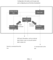
- FIG. 1 shows a structural schematic diagram of a fire alarm device 1000.
- the fire alarm device 1000 comprises an application-specific integrated circuit (ASIC) 110
- the application-specific integrated circuit (ASIC) 110 may be used to implement various functions related to the fire alarm, including, but not limited to, bus communication, smoke detection, button status detection, and so on.
- the fire alarm device 1000 is a smoke detector
- the application-specific integrated circuit (ASIC) 110 is used to implement functions such as bus communication, smoke detection, alarm, and so on.
- the fire alarm device 1000 is a manual fire alarm button (e.g. call point)
- the application-specific integrated circuit (ASIC) 110 is used to implement functions such as bus communication, button status detection, alarm, and so on.
- all logic units in the application-specific integrated circuit (ASIC) 110 are customised for a particular application, so programmers cannot change interconnections of a chip.
- the application-specific integrated circuit (ASIC) can include optimised storage units or mechanical structures, resulting in a smaller area of a final finished circuit compared to the CPU or MCU (e.g., the area is reduced to one-half or more of the area of the original CPU).
- the application-specific integrated circuit (ASIC) 110 comprises: a storage unit 112 for storing configuration data; a hardware encoder/decoder 114 for communicating with a bus; and a logic circuit 116 for receiving a parsed command from the hardware decoder and providing a returned command to the bus via the hardware encoder based on the configuration data, the returned command is used to indicate whether a fire exists.
- ASIC application-specific integrated circuit
- the configuration data comprises an address code (e.g. pre-written by an electronic encoder) unique for the fire alarm device 1000, whereby the address code may be used to distinguish between different fire alarm devices or on-site devices.
- the returned command contains this unique address code, enabling a fire alarm controller to locate an area where the fire alarm has occurred in a timely manner after receiving the returned command via the bus.
- the application-specific integrated circuit (ASIC) 110 may further comprise: a timing circuit 118 for providing a clock signal to the logic circuit 116 and the hardware encoder/decoder 114.
- the storage unit 112 is a flash (e.g. is or comprises flash storage), the flash receives the configuration data (e.g., less than 100 bytes) through a serial port. Thus, the storage unit 112 may use a very small-capacity flash.
- the above-described fire alarm device 1000 may further comprise: a general purpose input/output port, wherein the logic circuit 116 is configured to receive an external input and output alarm information via the general purpose input/output port.
- the above-described fire alarm device 1000 may further comprise: a bus interface, wherein the hardware encoder/decoder 114 is configured to communicate with the bus via the bus interface.
- the above-described fire alarm device 1000 may further comprise: a power management module coupled with the bus interface to power the application-specific integrated circuit (ASIC) 110 based on a command on the bus.
- ASIC application-specific integrated circuit
- FIG. 2 shows a schematic diagram of signal interaction between various modules within a fire alarm device.
- a flash 260 e.g. flash storage
- the configuration information may be provided to a hardware decoder 282, a logic circuit 220, and a hardware encoder 284.
- a timing circuit 240 may provide clock signals to the various modules (including the flash 260, the hardware decoder 282, the logic circuit 220, and the hardware encoder 284).
- the hardware decoder 282 is configured to decode a message received from the bus according to the configuration data to obtain the parsed command. The hardware decoder 282 then provides the parsed command to the logic circuit 220.
- the hardware encoder 284 is configured to encode data (e.g., the returned command) provided by the logic circuit 220 according to the configuration data, thereby uploading the encoded data to the bus.
- a fire alarm controller e.g. utilising non-polarity 2-bus technology
- the hardware decoder 282 receives the patrol command coming from the bus and parses the patrol command according to the bus protocol.
- the hardware encoder 284 encodes the command returning from the logic circuit 220 according to the bus protocol and uploads the encoded command to the bus.
- the logic circuit 220 may also interact with GPIO port (i.e., general purpose input/output port), for example, to receive a manual alarm button input or to provide an acoustic and/or optical alarm output, etc.
- GPIO port i.e., general purpose input/output port
- FIG. 3 shows a structural schematic diagram of a fire alarm device 3000.
- the fire alarm device 3000 may comprise: a general purpose input/output port 320 , a bus interface 330, and a power management module 340.
- the general purpose input/output port 320 is coupled with the application-specific integrated circuit ASIC 310 configured to receive an external input and output alarm information via the general purpose input/output port 320.
- the application-specific integrated circuit (ASIC) 310 is configured to receive the external input (i.e., alarm button input) via the general purpose input/output port 320.
- the application-specific integrated circuit (ASIC) 310 may also emit an acoustic and/or optical alarm through its own or an external alarm device via the general purpose input/output port 320.
- the application-specific integrated circuit (ASIC) 310 is also configured to couple with the bus interface 330 for communicating with the bus via the bus interface 330.
- the bus interface 330 is also configured to couple with the power management module 340, which is particularly useful in some cases.
- a battery unit may comprise a main power source and a backup power source, and under normal circumstances, the power management module 340 is configured to utilise the main power source to power various modules within the fire alarm device 3000. And when a fire, accident, or other emergency situation in a building results in a utility power failure, the power management module 340 is configured to switch from the main power source to the backup power source, in order to ensure that the fire alarm device 3000 can operate properly.
- FIG. 4 shows a structural schematic diagram of a fire alarm system 4000.
- the fire alarm system 4000 comprises a controller 410 and a plurality of fire alarm devices (e.g., fire alarm devices 422, 424, 426, etc.).
- the fire alarm devices 422, 424, 426, etc. are connected with the controller 410 by means of a 2-bus.
- the controller 410 may periodically send patrol commands to various fire alarm devices in order to monitor the proper operation of the fire alarm system 4000 and to give acoustic and/or optical alarms for specific faults.
- the controller 410 may be configured to receive fire signals from various fire alarm devices and to activate the fire alarm devices.
- the controller 410 may also be configured to indicate the location of the fire and record related information.
- the controller 410 may also be configured to activate a fire alarm signal through a fire alarm sending device and/or may be configured to activate an automatic fire extinguishing device and a fire linkage control device through an automatic fire extinguishing control device.
- modules illustrated as separate components may also not be physically separated, i.e. they may be located in one place or may also be distributed to a plurality of network modules. Some or all of these modules can be selected to fulfill the purpose of the solution of the embodiments according to actual needs. It can be understood and implemented by a person of ordinary skill in the art without creative labor.
- the fire alarm device of embodiments of the present invention may realise one or more of the functions of bus communication, smoke detection, and button status detection, etc., through the application-specific integrated circuit (ASIC) (e.g. instead of a CPU or MCU), thereby potentially greatly reducing the chip wafer area.
- ASIC application-specific integrated circuit
- the watchdog, RAM, large-capacity Flash, timer, and other modules in the CPU may no longer be needed in the application-specific integrated circuit (ASIC) (e.g., the CPU needs a large Flash to store the C program, whereas the solution of the embodiments of the present invention may need only a very small-capacity storage unit to store (e.g., less than 100 bytes) configuration information), and because the entire ASIC is a customised circuit, it may have lower power consumption, lower cost and better computing performance (compared to the CPU or MCU).
- ASIC application-specific integrated circuit
Landscapes
- Engineering & Computer Science (AREA)
- Physics & Mathematics (AREA)
- General Physics & Mathematics (AREA)
- Emergency Management (AREA)
- Business, Economics & Management (AREA)
- Computer Networks & Wireless Communication (AREA)
- Signal Processing (AREA)
- Theoretical Computer Science (AREA)
- Chemical & Material Sciences (AREA)
- Analytical Chemistry (AREA)
- General Engineering & Computer Science (AREA)
- Computer Security & Cryptography (AREA)
- Alarm Systems (AREA)
- Fire Alarms (AREA)
Abstract
Description
- The present invention relates to the field of fire alarms and, more specifically, to a fire alarm device and system.
- Fire is one of the common disasters that causes huge loss, which can be greatly reduced if it is detected in time and handled as early as possible. Therefore, on-site devices or fire alarm devices (e.g., smoke detectors, input/output modules, acoustic/optical alarms, manual fire alarm buttons, etc.) are set up for areas with potential fire risks. In an early stage of a fire or when a fire may occur, the on-site devices provide alarm prompts after detecting suspicious signals or receiving external alarm inputs, so that relevant personnel can deal with the fire in time to minimise the loss.
- For existing fire alarm devices, in order to ensure its functionality, an embedded central computing unit CPU (or microcontroller MCU) is usually set in the fire alarm device, and software programming is performed on the CPU or MCU to achieve bus communication, smoke detection algorithm, button status checking, and other functions. However, the CPU or MCU (in order to ensure its universality) generally contains a large number of modules, such as CPU core (e.g., for running C code), flash memory (e.g., for storing code), random access memory RAM, clock generator, watchdog timer (e.g., for monitoring abnormal status), basic interval timer (e.g., for generating heartbeat signals), counter, analog-to-digital converter, peripheral bridge, and so on. In this way, the use of the CPU or MCU can bring flexibility in usage (such as more flexible programming), but it also leads to higher power consumption, larger chip wafer area (such as due to more memory), and reduced computation capability.
- According to a first aspect of the invention, there is provided a fire alarm device, the device comprising: an application-specific integrated circuit (ASIC) for performing one or more of bus communication, smoke detection, and button status detection, wherein the application-specific integrated circuit (ASIC) comprises: a storage unit for storing configuration data; a hardware encoder/decoder for communicating with a bus; and a logic circuit for receiving a parsed command from the hardware decoder and providing a returned command to the bus via the hardware encoder based on the configuration data, the returned command is used to indicate whether a fire exists.
- The hardware encoder/decoder (i.e. hardware encoder and hardware decoder) may be provided by a single component providing both encoding and decoding functions or separate components each providing encoding or decoding function respectively.
- Optionally, in the device, the hardware decoder is used to decode a message received from the bus according to the configuration data to obtain the parsed command.
- Optionally, in the device, the hardware encoder is used to encode data provided by the logic circuit according to the configuration data to upload the encoded data to the bus.
- Optionally, in the device, the application-specific integrated circuit (ASIC) further comprises: a timing circuit for providing a clock signal to the logic circuit and the hardware encoder/decoder.
- Optionally, in the device, the storage unit is a flash (i.e. the storage unit comprises flash storage), wherein the flash receives the configuration data through a serial port.
- Optionally, the device further comprises: a general purpose input/output port, wherein the logic circuit is configured to receive an external input and output alarm information via the general purpose input/output port.
- Optionally, the device further comprises: a bus interface, wherein the hardware encoder/decoder is configured to communicate with the bus via the bus interface.
- Optionally, the device further comprises: a power management module coupled with the bus interface to power the application-specific integrated circuit (ASIC) based on a command on the bus.
- Optionally, in the device, the fire alarm device is any one of an input/output module, an acoustic/optical alarm, a manual fire alarm button, and a smoke detector.
- According to a second aspect of the present invention, there is provided a fire alarm system, the system comprising: a fire alarm device as previously described; and a controller, wherein the controller controls the fire alarm device via the bus.
- The fire alarm device may realise one or more of the functions of bus communication, smoke detection, and button status detection, etc., through the application-specific integrated circuit ASIC (instead of a CPU or MCU), thereby greatly reducing the chip wafer area. For example, the watchdog, RAM, large-capacity Flash, timer, and other modules in the CPU may no longer be needed in the application-specific integrated circuit ASIC (e.g., the CPU needs a large Flash to store the C program, whereas the invention may need only a very small-capacity storage unit to store (e.g., less than 100 bytes) of configuration information), and because the entire ASIC circuit may be a customised circuit, it may have lower power consumption, lower cost and better computing performance (compared to the CPU or MCU).
- The above and other potential purposes and advantages of the present invention will be made more complete and clear from the following detailed description in conjunction with the accompanying drawings, in which the same or similar elements are denoted by the same reference numerals.
- Certain exemplary embodiments will now be described in greater detail by way of example only and with reference to the accompanying drawings in which:
-
FIG. 1 shows a structural schematic diagram of a fire alarm device; -
FIG. 2 shows a schematic diagram of signal interaction between various modules within a fire alarm device; -
FIG. 3 shows a structural schematic diagram of a fire alarm device; and -
FIG. 4 shows a structural schematic diagram of a fire alarm system. - The following will provide a further detailed description of the potential embodiments of the present invention in conjunction with the accompanying drawings. The following embodiments are used to illustrate the present invention, but should not be used to limit the scope of the present invention, which is as set out in the appended claims.
- In the description of the present specification, the description referring to the terms "one embodiment", "some embodiments", "an example", "specific examples", or "some examples", etc., means that the specific features, structures, materials, or characteristics described in conjunction with the embodiment or example are included in at least one embodiment or example of the embodiments of the present invention. In this specification, schematic expressions of the above terms need not be directed to the same embodiment or example. Moreover, the specific features, structures, materials, or characteristics described may be combined in any one or more of the embodiments or examples in a suitable manner. Furthermore, the terms "first", "second", and "third" are used for descriptive purposes only and are not to be construed as indicating or implying relative importance. Furthermore, without contradicting each other, a person skilled in the art may combine the different embodiments or examples and the characteristics of the different embodiments or examples described in this specification.
-
FIG. 1 shows a structural schematic diagram of afire alarm device 1000. As shown inFIG. 1 , thefire alarm device 1000 comprises an application-specific integrated circuit (ASIC) 110, the application-specific integrated circuit (ASIC) 110 may be used to implement various functions related to the fire alarm, including, but not limited to, bus communication, smoke detection, button status detection, and so on. For example, where thefire alarm device 1000 is a smoke detector, the application-specific integrated circuit (ASIC) 110 is used to implement functions such as bus communication, smoke detection, alarm, and so on. For example, where thefire alarm device 1000 is a manual fire alarm button (e.g. call point), the application-specific integrated circuit (ASIC) 110 is used to implement functions such as bus communication, button status detection, alarm, and so on. - In one or more embodiments, all logic units in the application-specific integrated circuit (ASIC) 110 are customised for a particular application, so programmers cannot change interconnections of a chip. The application-specific integrated circuit (ASIC) can include optimised storage units or mechanical structures, resulting in a smaller area of a final finished circuit compared to the CPU or MCU (e.g., the area is reduced to one-half or more of the area of the original CPU).
- With continued reference to
FIG. 1 , the application-specific integrated circuit (ASIC) 110 comprises: astorage unit 112 for storing configuration data; a hardware encoder/decoder 114 for communicating with a bus; and alogic circuit 116 for receiving a parsed command from the hardware decoder and providing a returned command to the bus via the hardware encoder based on the configuration data, the returned command is used to indicate whether a fire exists. - In one embodiment, the configuration data comprises an address code (e.g. pre-written by an electronic encoder) unique for the
fire alarm device 1000, whereby the address code may be used to distinguish between different fire alarm devices or on-site devices. In one embodiment, the returned command contains this unique address code, enabling a fire alarm controller to locate an area where the fire alarm has occurred in a timely manner after receiving the returned command via the bus. - In one embodiment, the application-specific integrated circuit (ASIC) 110 may further comprise: a
timing circuit 118 for providing a clock signal to thelogic circuit 116 and the hardware encoder/decoder 114. In one embodiment, thestorage unit 112 is a flash (e.g. is or comprises flash storage), the flash receives the configuration data (e.g., less than 100 bytes) through a serial port. Thus, thestorage unit 112 may use a very small-capacity flash. - Although not shown in
FIG. 1 , in one embodiment, the above-describedfire alarm device 1000 may further comprise: a general purpose input/output port, wherein thelogic circuit 116 is configured to receive an external input and output alarm information via the general purpose input/output port. In one embodiment, the above-describedfire alarm device 1000 may further comprise: a bus interface, wherein the hardware encoder/decoder 114 is configured to communicate with the bus via the bus interface. In one embodiment, the above-describedfire alarm device 1000 may further comprise: a power management module coupled with the bus interface to power the application-specific integrated circuit (ASIC) 110 based on a command on the bus. - In one or more embodiments, the
fire alarm device 1000 may be or comprise any one of an input and/or output module, an acoustic and/or optical alarm, a manual fire alarm button, and a smoke detector. - Referring to
FIG. 2, FIG. 2 shows a schematic diagram of signal interaction between various modules within a fire alarm device. As shown inFIG. 2 , a flash 260 (e.g. flash storage) is configured to receive the configuration information through the serial port, such as configuring once at the time of production. The configuration information may be provided to ahardware decoder 282, alogic circuit 220, and ahardware encoder 284. In addition, atiming circuit 240 may provide clock signals to the various modules (including theflash 260, thehardware decoder 282, thelogic circuit 220, and the hardware encoder 284). - In one embodiment, the
hardware decoder 282 is configured to decode a message received from the bus according to the configuration data to obtain the parsed command. Thehardware decoder 282 then provides the parsed command to thelogic circuit 220. In one embodiment, thehardware encoder 284 is configured to encode data (e.g., the returned command) provided by thelogic circuit 220 according to the configuration data, thereby uploading the encoded data to the bus. For example, a fire alarm controller (e.g. utilising non-polarity 2-bus technology) sends a patrol command to each on-site device (i.e., fire alarm device) during a patrol cycle. Thehardware decoder 282 receives the patrol command coming from the bus and parses the patrol command according to the bus protocol. Similarly, thehardware encoder 284 encodes the command returning from thelogic circuit 220 according to the bus protocol and uploads the encoded command to the bus. - In addition, as shown in
FIG. 2 , thelogic circuit 220 may also interact with GPIO port (i.e., general purpose input/output port), for example, to receive a manual alarm button input or to provide an acoustic and/or optical alarm output, etc. -
FIG. 3 shows a structural schematic diagram of afire alarm device 3000. As shown inFIG. 3 , in addition to an application-specific integrated circuit (ASIC) 310, thefire alarm device 3000 may comprise: a general purpose input/output port 320 , a bus interface 330, and apower management module 340. Wherein, the general purpose input/output port 320 is coupled with the application-specificintegrated circuit ASIC 310 configured to receive an external input and output alarm information via the general purpose input/output port 320. For example, where thefire alarm device 3000 is a manual fire alarm button, the application-specific integrated circuit (ASIC) 310 is configured to receive the external input (i.e., alarm button input) via the general purpose input/output port 320. The application-specific integrated circuit (ASIC) 310 may also emit an acoustic and/or optical alarm through its own or an external alarm device via the general purpose input/output port 320. - The application-specific integrated circuit (ASIC) 310 is also configured to couple with the bus interface 330 for communicating with the bus via the bus interface 330. The bus interface 330 is also configured to couple with the
power management module 340, which is particularly useful in some cases. For example, a battery unit may comprise a main power source and a backup power source, and under normal circumstances, thepower management module 340 is configured to utilise the main power source to power various modules within thefire alarm device 3000. And when a fire, accident, or other emergency situation in a building results in a utility power failure, thepower management module 340 is configured to switch from the main power source to the backup power source, in order to ensure that thefire alarm device 3000 can operate properly. -
FIG. 4 shows a structural schematic diagram of afire alarm system 4000. As shown inFIG. 4 , thefire alarm system 4000 comprises acontroller 410 and a plurality of fire alarm devices (e.g.,fire alarm devices fire alarm devices controller 410 by means of a 2-bus. Thecontroller 410 may periodically send patrol commands to various fire alarm devices in order to monitor the proper operation of thefire alarm system 4000 and to give acoustic and/or optical alarms for specific faults. - The
controller 410 may be configured to receive fire signals from various fire alarm devices and to activate the fire alarm devices. Thecontroller 410 may also be configured to indicate the location of the fire and record related information. Thecontroller 410 may also be configured to activate a fire alarm signal through a fire alarm sending device and/or may be configured to activate an automatic fire extinguishing device and a fire linkage control device through an automatic fire extinguishing control device. - It is to be noted that the above-described embodiments of the device are merely schematic, wherein the modules illustrated as separate components may also not be physically separated, i.e. they may be located in one place or may also be distributed to a plurality of network modules. Some or all of these modules can be selected to fulfill the purpose of the solution of the embodiments according to actual needs. It can be understood and implemented by a person of ordinary skill in the art without creative labor.
- In summary, the fire alarm device of embodiments of the present invention may realise one or more of the functions of bus communication, smoke detection, and button status detection, etc., through the application-specific integrated circuit (ASIC) (e.g. instead of a CPU or MCU), thereby potentially greatly reducing the chip wafer area. For example, the watchdog, RAM, large-capacity Flash, timer, and other modules in the CPU may no longer be needed in the application-specific integrated circuit (ASIC) (e.g., the CPU needs a large Flash to store the C program, whereas the solution of the embodiments of the present invention may need only a very small-capacity storage unit to store (e.g., less than 100 bytes) configuration information), and because the entire ASIC is a customised circuit, it may have lower power consumption, lower cost and better computing performance (compared to the CPU or MCU).
- Although preferred embodiments of the present invention have been described, those skilled in the art may make additional changes and modifications to these embodiments once they have knowledge of the basic inventive concepts. Therefore, the appended claims are intended to be construed to include the preferred embodiments as well as all changes and modifications that fall within the scope of the present invention as set out in the appended claims. Obviously, those skilled in the art may make various changes and variations to the invention without departing from the scope of the present invention as set out in the appended claims. Thus, to the extent that such changes and variations fall within the scope of the claims of the present invention the present specification is intended to encompass such changes and variations.
Claims (10)
- A fire alarm device (1000;3000;422,424,426), comprising:
an application-specific integrated circuit (ASIC) (110;310) for performing one or more of bus communication, smoke detection, and button status detection, wherein the application-specific integrated circuit (ASIC) (110;310) comprises:a storage unit (112) for storing configuration data;a hardware encoder/decoder (114;282,284) for communicating with a bus; anda logic circuit (116;220) for receiving a parsed command from the hardware decoder (114;282) and providing a returned command to the bus via the hardware encoder (114;284) based on the configuration data, wherein the returned command is used to indicate whether a fire exists. - The device of claim 1, wherein the hardware decoder (114;282) is used to decode a message received from the bus according to the configuration data to obtain the parsed command.
- The device of claim 1 or 2, wherein the hardware encoder (114;284) is used to encode data provided by the logic circuit (116;220) according to the configuration data to upload the encoded data to the bus.
- The device of claim 1, 2 or 3, wherein the application-specific integrated circuit (ASIC) (110;310) further comprises: a timing circuit (118;240) for providing a clock signal to the logic circuit and the hardware encoder/decoder (114;282,284).
- The device of any preceding claim, wherein the storage unit is a flash (260), the flash (260) receives the configuration data through a serial port.
- The device of any preceding claim, wherein the device further comprises: a general purpose input/output port (320), wherein the logic circuit (116;220) is configured to receive an external input and output alarm information via the general purpose input/output port (320).
- The device of any preceding claim, wherein the device further comprises: a bus interface (330), wherein the hardware encoder/decoder (114;282,284) is configured to communicate with the bus via the bus interface (330).
- The device of claim 7, wherein the device further comprises: a power management module (340) coupled with the bus interface (330) to power the application-specific integrated circuit (ASIC) (110;310) based on a command on the bus.
- The device of any preceding claim, wherein the fire alarm device is any one of an input/output module, an acoustic/optical alarm, a manual fire alarm button, and a smoke detector.
- A fire alarm system (4000) comprising:a fire alarm device (1000;3000;422,424,426) of any one of claims 1 to 9; anda controller (410), wherein the controller controls the fire alarm device via a bus.
Applications Claiming Priority (1)
| Application Number | Priority Date | Filing Date | Title |
|---|---|---|---|
| CN202211498118.2A CN118135723A (en) | 2022-11-28 | 2022-11-28 | Fire alarm equipment and systems |
Publications (1)
| Publication Number | Publication Date |
|---|---|
| EP4375964A1 true EP4375964A1 (en) | 2024-05-29 |
Family
ID=88978492
Family Applications (1)
| Application Number | Title | Priority Date | Filing Date |
|---|---|---|---|
| EP23212760.5A Pending EP4375964A1 (en) | 2022-11-28 | 2023-11-28 | Fire alarm device and system |
Country Status (3)
| Country | Link |
|---|---|
| US (1) | US12614437B2 (en) |
| EP (1) | EP4375964A1 (en) |
| CN (1) | CN118135723A (en) |
Citations (2)
| Publication number | Priority date | Publication date | Assignee | Title |
|---|---|---|---|---|
| US20150077240A1 (en) * | 2013-09-17 | 2015-03-19 | Microchip Technology Incorporated | Smoke Detector with Enhanced Audio and Communications Capabilities |
| US20170134895A1 (en) * | 2015-11-06 | 2017-05-11 | Google Inc. | Adjusting security in response to alert communications |
Family Cites Families (42)
| Publication number | Priority date | Publication date | Assignee | Title |
|---|---|---|---|---|
| US6107925A (en) | 1993-06-14 | 2000-08-22 | Edwards Systems Technology, Inc. | Method for dynamically adjusting criteria for detecting fire through smoke concentration |
| US5691704A (en) | 1996-01-29 | 1997-11-25 | Engelhard Sensor Technologies, Inc. | Practical and improved fire detector |
| US5945924A (en) | 1996-01-29 | 1999-08-31 | Marman; Douglas H. | Fire and smoke detection and control system |
| US6078269A (en) | 1997-11-10 | 2000-06-20 | Safenight Technology Inc. | Battery-powered, RF-interconnected detector sensor system |
| US6313744B1 (en) | 1998-03-25 | 2001-11-06 | Simplex Time Recorder Company | Alarm system with individual alarm indicator testing |
| US6362743B1 (en) | 1999-09-09 | 2002-03-26 | Ranco Incorporated Of Delaware | Smoke alarm with dual sensing technologies and dual power sources |
| EP1098284B1 (en) | 1999-11-05 | 2004-05-06 | E.I. Technology Limited | A smoke alarm device |
| US6166647A (en) | 2000-01-18 | 2000-12-26 | Jaesent Inc. | Fire detector |
| US6958689B2 (en) * | 2001-09-21 | 2005-10-25 | Rosemount Aerospace Inc. | Multi-sensor fire detector with reduced false alarm performance |
| EP1369836B1 (en) | 2002-05-08 | 2005-12-21 | HEKATRON Technik GmbH | Smoke detector and method for its operation |
| US7830252B2 (en) | 2003-08-14 | 2010-11-09 | Wheelock, Inc. | Method and apparatus for providing an ASIC controlled alarm unit |
| US7375642B2 (en) * | 2004-08-24 | 2008-05-20 | Wagner Alarm- Und Sicherungssysteme Gmbh | Method and device for identifying and localizing a fire |
| US7408839B2 (en) | 2004-09-09 | 2008-08-05 | Siemens Building Technologies, Inc. | Distance measurement for wireless building automation devices |
| GB0504658D0 (en) * | 2005-03-07 | 2005-04-13 | Texas Instruments Ltd | PC - connectivity for on-chip memory |
| US7994928B2 (en) | 2007-05-25 | 2011-08-09 | Robert Charles Richmond | Multifunction smoke alarm unit |
| US7679547B2 (en) | 2007-09-26 | 2010-03-16 | Honeywell International Inc. | Direction of travel motion detector with automatic gain control |
| US8766807B2 (en) * | 2008-10-03 | 2014-07-01 | Universal Security Instruments, Inc. | Dynamic alarm sensitivity adjustment and auto-calibrating smoke detection |
| EP2306419B1 (en) | 2009-09-30 | 2016-11-02 | Siemens Schweiz AG | Calibration of an electro-optical signal path of a sensor device by means of online signal level monitoring |
| US8378806B2 (en) | 2010-09-17 | 2013-02-19 | Simplexgrinnell Lp | Pseudo non-addressable alarm system |
| GB2484288A (en) | 2010-10-04 | 2012-04-11 | Thorn Security | Isolator Circuit for detector |
| US8760280B2 (en) | 2011-07-28 | 2014-06-24 | Tyco Fire & Security Gmbh | Method and apparatus for communicating with non-addressable notification appliances |
| US9030328B2 (en) | 2012-10-10 | 2015-05-12 | Siemens Aktiengsellschaft | Integrated circuit to operate in an area of ionizing radiation, and having an output for a radiation dose-dependent way damage information, and alarm indicators and corresponding method |
| US9373245B2 (en) | 2013-02-22 | 2016-06-21 | Cooper Technologies Company | Smart notification appliances |
| US20140266777A1 (en) | 2013-03-15 | 2014-09-18 | Leeo, Inc. | Environmental monitoring device |
| US9159218B2 (en) | 2013-09-17 | 2015-10-13 | Microchip Technology Incorporated | Initiation of carbon monoxide and/or smoke detector alarm test using image recognition and/or facial gesturing |
| US9117360B1 (en) | 2014-06-06 | 2015-08-25 | Fred Conforti | Low battery trouble signal delay in smoke detectors |
| US10008105B2 (en) | 2015-09-30 | 2018-06-26 | Tyco Fire & Security Gmbh | System and method for charging supplemental power units for alarm notification devices |
| US9922509B2 (en) | 2016-01-22 | 2018-03-20 | Tyco Fire & Security Gmbh | Strobe notification appliance with directional information |
| JP6321063B2 (en) | 2016-02-29 | 2018-05-09 | 能美防災株式会社 | Fire monitoring system and smoke detector |
| US10473777B2 (en) | 2016-08-31 | 2019-11-12 | Robert Bosch Gmbh | ASIC implemented motion detector |
| US9967955B2 (en) * | 2016-09-28 | 2018-05-08 | Platformatics Inc. | Power over ethernet lighting system with emergency mode |
| US10282975B2 (en) | 2017-08-08 | 2019-05-07 | Microchip Technology Incorporated | Carbon monoxide alarm supervision |
| CA3020553A1 (en) | 2017-10-17 | 2019-04-17 | Pierre Desjardins | Interconnecting detector |
| CN111263958B (en) | 2017-10-30 | 2022-05-27 | 开利公司 | Compensator in detector device |
| WO2019183530A1 (en) * | 2018-03-23 | 2019-09-26 | Tyco Fire Products Lp | Automated self-targeting fire suppression systems and methods |
| GB2581349A (en) | 2019-02-12 | 2020-08-19 | Johnson Controls Fire Prot Lp | Voice alarm device |
| US11195400B2 (en) | 2019-02-20 | 2021-12-07 | Jade Bird Fire Co., Ltd. | Smoke detector and method for detecting smoke |
| CN109979151B (en) | 2019-03-28 | 2021-03-16 | 赛特威尔电子股份有限公司 | A smoke alarm method, device, smoke alarm device and storage medium |
| CN214504164U (en) | 2021-02-23 | 2021-10-26 | 四川海丝科技有限公司 | Intelligent well lid detection circuit |
| CN216310993U (en) | 2021-10-13 | 2022-04-15 | 中讯博尔智能技术(无锡)有限公司 | Power monitoring device with power distribution cabinet smoke monitoring function |
| KR102679229B1 (en) * | 2022-01-19 | 2024-06-26 | 주식회사 엘지에너지솔루션 | Apparatus and method for fire monitoring |
| EP4443405A1 (en) * | 2023-04-03 | 2024-10-09 | Carrier Corporation | A trim element for a fire detection system and a method thereof |
-
2022
- 2022-11-28 CN CN202211498118.2A patent/CN118135723A/en active Pending
-
2023
- 2023-11-21 US US18/516,925 patent/US12614437B2/en active Active
- 2023-11-28 EP EP23212760.5A patent/EP4375964A1/en active Pending
Patent Citations (2)
| Publication number | Priority date | Publication date | Assignee | Title |
|---|---|---|---|---|
| US20150077240A1 (en) * | 2013-09-17 | 2015-03-19 | Microchip Technology Incorporated | Smoke Detector with Enhanced Audio and Communications Capabilities |
| US20170134895A1 (en) * | 2015-11-06 | 2017-05-11 | Google Inc. | Adjusting security in response to alert communications |
Also Published As
| Publication number | Publication date |
|---|---|
| CN118135723A (en) | 2024-06-04 |
| US12614437B2 (en) | 2026-04-28 |
| US20240177585A1 (en) | 2024-05-30 |
Similar Documents
| Publication | Publication Date | Title |
|---|---|---|
| US5283905A (en) | Power supply for computer system manager | |
| CN112099412B (en) | A Safe Redundancy Architecture for Micro Control Units | |
| TW201638899A (en) | Multi-layer wireless communication | |
| CN115705267A (en) | Monitoring acquisition equipment, and main/standby switching method and system based on monitoring acquisition equipment | |
| CN1941015B (en) | A Distributed Monitoring Method | |
| US12614437B2 (en) | Fire alarm device and system | |
| WO1987006750A1 (en) | Fire alarm facility | |
| CN112636762A (en) | Battery management system, slave control encoding method and device | |
| JP2002269661A (en) | Abnormality informing system for fuel cell system for domestic use | |
| CN105389963A (en) | Multipath voice alarm system | |
| KR101655282B1 (en) | Apparatus for managing dual level reset of microgrid gateway for new regeneration energy management system and method thereof | |
| CN119536485A (en) | Power management control system and method, server, electronic device and storage medium | |
| EP3555871B1 (en) | Fire-prevention control unit | |
| CN105632070A (en) | Intelligent fire detector alarm system | |
| JP5324300B2 (en) | Alarm and alarm system | |
| CN118011974A (en) | Control module applied to DCS system and control method thereof | |
| JPH0742061B2 (en) | Elevator remote monitoring device | |
| JP3248483B2 (en) | Alarm processing device | |
| EP4472148A1 (en) | Method and device for encoding battery management system | |
| CN103731635B (en) | A kind of mobile ad-hoc network intelligent monitor system and its implementation | |
| JP7624838B2 (en) | Communication Equipment | |
| CN111522718A (en) | A server power supply system and a server | |
| TWI782305B (en) | Server system | |
| JPS60112109A (en) | Detector of faulty part | |
| JPS62263599A (en) | Multiple control system for housing |
Legal Events
| Date | Code | Title | Description |
|---|---|---|---|
| PUAI | Public reference made under article 153(3) epc to a published international application that has entered the european phase |
Free format text: ORIGINAL CODE: 0009012 |
|
| STAA | Information on the status of an ep patent application or granted ep patent |
Free format text: STATUS: THE APPLICATION HAS BEEN PUBLISHED |
|
| AK | Designated contracting states |
Kind code of ref document: A1 Designated state(s): AL AT BE BG CH CY CZ DE DK EE ES FI FR GB GR HR HU IE IS IT LI LT LU LV MC ME MK MT NL NO PL PT RO RS SE SI SK SM TR |
|
| STAA | Information on the status of an ep patent application or granted ep patent |
Free format text: STATUS: REQUEST FOR EXAMINATION WAS MADE |
|
| 17P | Request for examination filed |
Effective date: 20241112 |
|
| RBV | Designated contracting states (corrected) |
Designated state(s): AL AT BE BG CH CY CZ DE DK EE ES FI FR GB GR HR HU IE IS IT LI LT LU LV MC ME MK MT NL NO PL PT RO RS SE SI SK SM TR |
|
| STAA | Information on the status of an ep patent application or granted ep patent |
Free format text: STATUS: EXAMINATION IS IN PROGRESS |
|
| 17Q | First examination report despatched |
Effective date: 20250303 |