EP4375787A1 - Verfahren zur steuerung eines hydronischen heizsystems und steuerungssystem für ein hydronisches heizsystem - Google Patents
Verfahren zur steuerung eines hydronischen heizsystems und steuerungssystem für ein hydronisches heizsystem Download PDFInfo
- Publication number
- EP4375787A1 EP4375787A1 EP22209275.1A EP22209275A EP4375787A1 EP 4375787 A1 EP4375787 A1 EP 4375787A1 EP 22209275 A EP22209275 A EP 22209275A EP 4375787 A1 EP4375787 A1 EP 4375787A1
- Authority
- EP
- European Patent Office
- Prior art keywords
- heat
- thermostat
- thermal zone
- duty cycle
- zone
- Prior art date
- Legal status (The legal status is an assumption and is not a legal conclusion. Google has not performed a legal analysis and makes no representation as to the accuracy of the status listed.)
- Granted
Links
Images


Classifications
-
- G—PHYSICS
- G05—CONTROLLING; REGULATING
- G05D—SYSTEMS FOR CONTROLLING OR REGULATING NON-ELECTRIC VARIABLES
- G05D23/00—Control of temperature
- G05D23/19—Control of temperature characterised by the use of electric means
- G05D23/1927—Control of temperature characterised by the use of electric means using a plurality of sensors
- G05D23/193—Control of temperature characterised by the use of electric means using a plurality of sensors sensing the temperaure in different places in thermal relationship with one or more spaces
- G05D23/1932—Control of temperature characterised by the use of electric means using a plurality of sensors sensing the temperaure in different places in thermal relationship with one or more spaces to control the temperature of a plurality of spaces
- G05D23/1934—Control of temperature characterised by the use of electric means using a plurality of sensors sensing the temperaure in different places in thermal relationship with one or more spaces to control the temperature of a plurality of spaces each space being provided with one sensor acting on one or more control means
Definitions
- the present invention relates to a method for controlling a hydronic heating system comprising a plurality of thermal zones, in particular an underfloor heating system for a plurality of rooms of a building.
- the present invention further relates to a control system for such a hydronic heating system.
- Hydronic heating systems i.e. heating systems wherein a liquid heating medium is provided to respective heat exchangers, and methods for their control are widely known.
- different types of hydronic underfloor and other panel heating systems have been developed.
- energy efficiency is improved, among others, by a relatively low supply temperature of the liquid heating medium as well as a relatively large area for transmitting the provided heat to the respective heating zone, such as a room of a building.
- the valves used to control the flow of the liquid heating medium into such heating systems are often hidden in the floors or walls of the building. Accordingly, the control valves and corresponding room thermostats, including any associated user control elements, for each heating zone are usually provided separately from each other and are connected to a central controller of the hydronic heating system.
- a method for controlling a hydronic heating system comprising a plurality of thermal zones, such as an underfloor heating system for a plurality of rooms of a building, is provided.
- the method comprises:
- thermostats can be interpreted as heat calls either demanding further heating for a respective thermal zone or not.
- a heating requirement for a respective room can be determined without explicit knowledge of a current set-point for the thermal zone.
- the determined heating requirement can be satisfied based on determined pulse width modulated (PWM) control signals.
- the described control method alleviates the need to retrieve additional information such as set-point values for each thermal zone.
- it can be implemented using a number of different thermostat types, such as electronic on/off thermostats, bimetal or membrane electromechanical thermostats.
- the use of PWM control signals allows the use of many different types of actuators, including simple shutoff valves. Since all input signals as well as output signals used by the disclosed control method are of a digital type, i.e. either on or off, it is relatively easy to convert respective signals to a desired voltage level, for example to include 12 V thermostats and 230 V thermostats in the same system.
- the heat calls can be analysed in many ways to obtain the desired control behaviour.
- the duty cycle of a respective PWM control signal is determined based on a proportion between a first duration of at least one heat call and a second duration of at least one interval between successive heat calls.
- the output PWM control value could be adapted from a previous PWM control value based on such a proportion to optimize the control.
- Further signal processing such as statistical analysis and/or filtering may be used to improve the accuracy and response speed of the disclosed control method.
- the method comprises storing timings of a plurality of heat calls and intervals between heat calls for each heating zone, computing an average heat call duration and an average interval between heat calls for each thermal zone, and determining a respective duty cycle for the respective thermal zone based on the average heat call duration and the average interval. Accordingly, an averaging of several heat calls can be achieved, thereby reducing the impact of untypically short or long heat calls.
- the method comprises detecting a pulsating mode of operation of a thermostat, in the case that a detected pulse lengths of a thermostat signal provided by the thermostat is shorter than a predetermined pulse mode timing threshold value, and/or detecting a non-pulsating or on/off mode of operation of a thermostat, in the case that the detected pulse lengths of the thermostat signal is longer than the predetermined pulse mode timing threshold value.
- the method may further comprise determining at least one of a pulse frequency, a pulse duration and/or an interval between multiple pulses of a digital thermostat signal of a thermostat detected to operate in the pulsating mode, and, based on the detected at least one of a pulse frequency, a pulse duration and/or an interval, generating a heat call signal for the respective thermostat, selective indicating a demand for heat in the respective thermal zone.
- a pulse frequency of multiple pulses of a pulsating thermostat signal may be determined. Only if the determined pulse frequency exceeds a predetermined frequency threshold, the corresponding digital thermostat signal may be considered to indicate a heat call.
- a length or average length of one or more pulses of a pulsating thermostat signal may be determined. Only if the determined pulse lengths exceeds a predetermined length threshold, the corresponding digital thermostat signal may be considered to indicate a heat call.
- the method comprises initializing the duty cycle of the PWM control signal for each thermal zone with a predetermined value, in particular a duty cycle of 50%, increasing the duty cycle of the PWM control signal for a thermal zone in the case that a duration of at least one heat call of the respective thermal zone exceeds a first threshold value, and decreasing the duty cycle of the PWM control signal for thermal zone in the case that a duration of the at least one heat call of the respective thermal zone does not exceed a second threshold value.
- the method comprises prolonging a flow of the liquid heating medium to a single thermal zone up to a predetermined duration, in the case that the flow of liquid heating medium to all other thermal zones has been deactivated.
- this prevents interruption of the liquid heating medium in the hydronic heating system for the predetermined duration, thereby preventing frequent starting and stopping of other components, such as a heat pump and/or a circulating pump.
- the method comprises computing an average duration of heat calls for each thermal zone based on a predetermined number of heat calls, computing an average interval between successive heat calls for each thermal zone based on a predetermined number of intervals, and calculating a time base for each thermal zone based on the respective average duration and average interval.
- a room-specific time base computed over a number of heat calls can help to quickly determine suitable threshold values for adjusting the PWM control signal.
- the duty cycle of the PWM control signal for a respective thermal zone is increased by a predetermined first part if the most recent heat call for a heating zone exceeds a first predetermined percentage of the time base.
- the duty cycle of the PWM control signal for the respective thermal zone is decreased by a predetermined second part if the most recent heat call for a heating zone does not exceed a second predetermined percentage of the time base. Accordingly, an adjustment of the PWM control signal can be triggered at the end of every heat call, thereby achieving a relatively fast response time.
- the duty cycle of the PWM control signal for the respective thermal zone is decreased by the second predetermined part only after detecting a predetermined number of, in particular two, successive heat calls for the respective thermal zone that fail to exceed the second predetermined percentage of the time base.
- the duty cycle of the PWM control signal for a respective thermal zone is increased by a third predetermined part if an ongoing heat call for a heating zone exceeds a third predetermined percentage of the time base.
- the response speed in the upward direction can be further reduced in that the algorithm does not need to wait for a current, very long heat call to end before adjusting the PWM control signal.
- a control system for a hydronic heating system in particular an underfloor heating system, is provided.
- the control system comprises:
- the disclosed control system enables to implement the control algorithm according to the first aspect in a system comprising a number of potentially different thermostats and actuators.
- the advantages of the claimed system essentially correspond to the respective advantages of the control method as detailed above.
- each one of the actuators comprises at least one of a mechanical piston valve or a solenoid valve. Such valves can be controlled using the provided PWM control signals.
- a computer program comprising instructions that, when executed by a controller, cause the controller to perform the method steps according to the control method of the first aspect.
- FIG. 1 shows the general setup of a hydronic heating system 10.
- the hydronic heating system 10 comprises a number of thermal zones 20a to 20c, whose temperature can be controlled separately.
- a controller 30 regulates a flow of liquid heating medium from a heat supply system 40 to the individual thermal zones 20a to 20c.
- the heat supply system 40 may comprise one or more heat sources 41, such as a heat pump or boiler, and one or more circulating means, such as a circulating pump 42.
- a liquid heating medium such as hot water is provided by the heat source 41 and circulated by the circulating pump 42 via supply lines towards the thermal zones 20a to 20c. Attention is drawn to the fact that, in the case of a heat pump being used as a heat source 41, an additional circulating pump 42 may not be necessary.
- Each thermal zone 20a to 20c comprises one or more heating loops 21a to 21c, such as a network of pipes integrated into a floor of a respective room. Whether or not the liquid heating medium provided by the heat supply system 40 is circulated through the respective heating loop 21a to 21c is controlled by one or more actuators 22a to 22c.
- a mechanical piston valve or solenoid valve may be used to selectively activate or deactivate a flow of the liquid heating medium.
- Each one of the actuators 22a to 22c is connected to the controller 30, which controls the provision of heating medium to all thermal zones 20a to 20c. Attention is drawn to the fact that it is sufficient for the described system if a respective flow of heating medium for one of the thermal zones 20a to 20c can be activated or deactivated. While it is also possible to use proportional valves as actuators 22a to 22c, in operation these may be controlled in the same way as a simple on/off valve, i.e. fully open or fully closed.
- a thermostat 23a to 23c is installed in each one of the thermal zones 20a to 20c.
- the thermostats 23a to 23c may be room thermostats of different types and/or operating voltage.
- conventional electromechanical bimetal thermostats may be used for the first thermal zone 20a.
- more modern, fully electronic thermostats may be employed.
- Each of the thermostats 23a to 23c provides a digital thermostat signal back to the controller 30, i.e. a signal with one of two possible signal levels. Due to the different nature of the respective thermostats 23a to 23c, the specific digital thermostat signals provided by them may differ, as detailed below. Nonetheless, the controller 30 unifies the received digital thermostat signal to either indicate a call or request for further heat or not, i.e. one of two possible states.
- FIG. 2 shows, in a schematic manner, the configuration of a controller 30.
- the controller 30 comprises a total of six control inputs 31 for receiving digital thermostat signals from six different thermal zones or thermostat channels.
- the controller 30 comprises corresponding input circuitry 32 for each control input 31, for example to connect a controller 30 to thermostats operating at different operating voltages, such as 12 V, 24 V and/or 230 V.
- the controller 30 further comprises corresponding control outputs 33.
- the controller 30 comprises a total of twelve control outputs. Similar to the control inputs 31, each one of the control outputs 33 has corresponding output circuitry 34 which provide suitable control signals for actuators, such as different types of valves attached to the controller 30.
- each thermal zone may be controlled by multiple control outputs 33 associated to the same thermostat channel. This is useful, in particular, for larger rooms having two separate heating loops arranged within the same thermal zone.
- the mapping between the six control inputs 31 and the twelve control outputs 33 is fixed, i.e. each thermostat channel of the controller 30 corresponding to one of the thermal zones 20a to 20c of the building has one corresponding control input 31 and two corresponding control outputs 33.
- this mapping may be different or more flexible, e.g. configurable through a user interface.
- the controller 30 has a day and night input 35, a pump relay output 36 and a power supply input 37. Via the day and night input 35, different operating modes for normal or reduced heating can be activated. Further inputs may be provided (not shown), for example for monitoring condensation or for switching from a heating to a cooling mode of operation of a heat pump.
- the pump relay output 36 controls a heating source 41 and/or circulating pump 42 of the heat supply system 40. In case these components are separate from each other, multiple control outputs may be provided (not shown) by the controller 30.
- the controller 30 may comprise a number of user interface elements 38 for manual configuration of the controller 30. However, as the described control system is mostly self-learning, details of the user interface elements 38 will not be described here.
- FIG. 3 shows, in a schematic manner, various processing blocks performed by the controller 30.
- the controller 30 may comprise a micro-processor and a memory for storing program code of a control program executed by the micro-processor.
- the controller 30 performs, in block 51a to 51b, pre-processing for each of the digital thermostat signals received for a respective thermal zone.
- Pre-processing may comprise, among others, the detection of the specific thermostat type attached to a respective control input 31, the mapping of the received raw thermostat signals to a corresponding heat call, and signal filtering. For example, very short ON periods of the digital thermostat signal, e.g. shorter than 90 seconds may be removed. Moreover, an average length of the ON and OFF periods of the digital thermostat signal and/or an average duration and interval between heat calls may be computed.
- the pre-processed heat calls are used by respective blocks 52a to 52n for adjusting a corresponding PWM control signal for each one of the thermal zones 20.
- a duty cycle is determined for each thermal zone 22a to 22n, which reflects the average demand for heat during a predetermined time period.
- the PWM control signal is later used to open or close a corresponding actuator 22a to 22n and thereby activate or deactivate a flow of liquid heating medium through corresponding heating loop 21a to 21n. Controlling the flow of liquid heating medium over time in turn allows to modulate the average amount of thermal energy provided to the respective heating zones 20a to 20c.
- a central control block 53 monitors the output of the PWM adjustment blocks 52 and may adjust the PWM control signals and/or provides further control signals. Such signals may be used to perform some central control tasks, such as providing a signal to the pump relay output 36 for activating or deactivating parts of the heat supply system 40.
- the central control block 53 may also implement thermal loop bypass function, which keeps at least one of the actuators 22 switched on for a predetermined amount of time to avoid a frequent activation and deactivation of a heat source 41, circulating pump 42 and/or other central component.
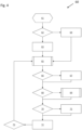
- Figure 4 shows a possible implementation of the control method 60 in the form of a flowchart.
- the method 60 starts at step 61, for example by switching on or otherwise providing power to the controller 30.
- the controller 30 optionally checks whether it is starting for the first time in step 62.
- Initialization may comprise detection of how many thermostats 23 and/or actuators 22 are actually connected to the controller 30.
- one or more parameters for each thermal zone 20 controlled by the controller 30 are initialized. For example, the duty cycle for a PWM control signal for each thermal zone may be set to a predetermined default value, such as 50%.
- Other initial parameters, such as a PWM modulation time, may also be determined and stored, for example in a non-volatile memory of the controller 30.
- step 64 previously stored configuration data may be loaded in a step 64, for example from a non-volatile memory of the controller 30. That is to say, in step 64 the last used values for the above parameters for each thermal zone and the controller 30 are restored. This enables the controller 30 to continue working based on previously learned parameters and therefore speeds up initialisation of the controller 30.
- thermostats and actuators associated with each one of the thermal zones 20 are managed within a control loop starting in step 65.
- samples of the digital thermostat signals are captured and used to determine if there is a current heat demand for a respective thermal zone 20a to 20c or not.
- the received digital thermostat signal corresponds to a heat call used by the remainder of the control loop.
- a conversion process may be used as detailed later with respect to Figures 7 and 8 .
- the disclosed system may operate with an auto-balancing feature activated or deactivated.
- This setting may be stored persistently as described above, or may be indicated by a jumper or other type of hardware or software switch.
- the digital thermostat signals provided by the respective room thermostats 23a to 23c or corresponding heat calls are provided directly to the respective actuators 21a, to 21c, respectively. That is to say, if a room thermostat indicates a demand for heat for a room, a flow of liquid heating medium through a corresponding heating loop will be activated. Inversely, if the room thermostat does not indicate a demand for heat, the flow will be deactivated.
- the controller 30 at first checks whether a heat call for a respective thermal zone has been switched to an ON state.
- the length of the previous interval i.e. the duration between successive heat calls for a given thermal zone
- the length of the previous interval is calculated and saved in an array of the last five heat call intervals in step 67.
- Very short intervals e.g. intervals of less than 90 seconds, may be omitted in step 67.
- a new average interval time between heat calls may be computed based on the array's content.
- step 68 the controller 30 checks whether a heat call has switched to an OFF state for one of the thermal zones. Accordingly, in a step 69, an array comprising the duration of the last five heat calls for the respective thermal zone is updated. As detailed above with regard to step 67, some filtering and averaging of the recorded ON times may be performed.
- this occasion is used to update the respective PWM control signal for the respective thermal zone 20. This process will be described later with respect to Figure 6 .
- step 70 a so-called continuous heat call may be detected. This means that a thermostat's request for heating for a corresponding thermal zone does not come to an end within an expected timeframe. This takes care of the case of a heating loop being significantly underpowered and therefor unable to reach the room's set-point in the PWM modulation interval.
- step 71 the duty cycle of the PWM control signal is increased even before the end of a heat call is detected in step 68.
- the duty cycle is increased by a fixed percentage, e.g. 6.6%, if the length of a currently running ON state of the digital demand signal exceeds a predefined threshold, e.g. 80% of the time base for the respective thermal zone 20.
- a step 72 the control outputs 33 for each thermostat channel of the controller 30 are activated or deactivated.
- This process uses the status and timing of the respective heat calls, a common timer and respective computed PWM control signals to decide if the respective control output 33 should be ON or OFF. Moreover, it uses a separate timer to handle a thermal loop bypass (TLBP) function to extend the time during which the last active output remains switched ON under the condition that the output 33 associated with the respective thermal zone 20 is the only one left that is active.
- TLBP thermal loop bypass
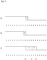
- Figure 5 shows three exemplary PWM control signals computed for three respective thermal zones 20a to 20c by the method 60 described above.
- the duty cycle for each signal corresponds to the relative length of activating the respective zones 20a to 20c within the PWM modulation time, e.g. each 30 minute interval of the described system.
- the duty cycle of the first PWM control signal has been slightly extended from an initial duty cycle of 50% (dashed) corresponding to time t0 to a duty cycle of, for example, 56.6% (solid).
- the PWM control signal for the second thermal zone 20b according to Figure 5 b) has been reduced from the initial PWM duty cycle of 50% to a reduced PWM duty cycle of, for example, 43.4%.
- the PWM control signal for the third thermal zone 20c has been extended to a much larger duty cycle of, for example, 69.8%. Accordingly, at time t1, at which the supply of the liquid heating medium should be deactivated for the thermal zone 20c, the third heating loop 21c is the last active heating loop. However, in order to implement a TLBP function as indicated above, the controller 30 compares the current time t1 with a pre-set minimum TLBP time for the heat supply system 40. If the minimum TLBP time has not been reached at moment t1, the controller 30 will essentially extend the PWM control signal for the last remaining heating loop 21c to time t2, at which the minimum TLBP time has expired. In the specific example, this may represent 80% of the PWM modulation time.
- a fixed operation time for the last active heating loop such as 30 or 45 minutes, may be configured as minimum TLBP time.
- the minimum TLBP time can be configured in an adaptive manner by using a part of the stored time values for historical heat call lengths.
- a step 73 the controller 30 checks whether a predetermined time has elapsed to start the next iteration of the control loop at step 65.
- the length of this so-called timer tick may be configured manually or may be predetermined. Due to the relatively slow nature of control signals involved in hydronic heating systems, a timer tick may correspond to 1 or 10 seconds or more, such as a minute.
- Figure 6 shows a more detailed flow chart of an exemplary process 80 for updating the respective PWM control signal and internal control variables used for auto-balancing the thermal zones 20a to 20c in more detail.
- the process 80 starts at step 81.
- this process is triggered in step 67, i.e. whenever the end of a heat call is detected.
- the PWM control signals may also be updated at the start of a heat call or at regular intervals.
- step 82 the length of the most recent heat call is stored in an array of the last five heat call durations. Moreover, particularly short heat calls may be filtered out. In other words, such particularly short heat calls may not be stored in the array. Thereafter, the average length of the last five heat call durations is computed.
- a new time base is calculated for the respective thermal zone.
- the time base corresponds to the duration of the last five intervals and the last five heat halls and starts with a value of 150 minutes.
- this parameter is adjusted accordingly to reflect the response time of the respective thermal zone.
- this self-adaption makes the system suitable for different installation types of the heating loops, for example heating loops directly embedded in a concrete floor slab or in a heating panel arranged above a floor insulation covering a concrete floor.
- the time base and at least in some configurations, the duration of individual heat calls, is typically much longer than the PWM modulation time. That is to say, during a single heat call received from one of the thermostats 23a to 23c a corresponding heating loop 21a to 21c of the same thermal zone 20a to 20c may be activated and deactivated repeatedly to provide a required average energy flow into the respective thermal zone 20a to 20c.
- the time base computed for each thermal zone is limited to a predetermined range, for example to a range between 30 and 500 minutes. Among others, this reduce a risk of flow starvation for longer heating loops when set-points are set unreasonable high on thermal zones with shorter heating loops.
- step 84 the length of the latest heat call is compared to a lower threshold to determine if it represents a so called short heat call.
- the lower threshold corresponds to 30% of the time base computed in step 83.
- step 85 If the last heat call is considered to be a short heat call, the method continues in step 85 to verify whether the currently processed heat call was the first or a subsequent heat call that did not exceed the lower threshold.
- the duty cycle of the corresponding PWM control signal is adjusted downwards by a predetermined amount. For example, in the specific embodiment, it is adjusted downwards by 6.6% of the current value.
- the size of the downwards adjustment may be specified as a percentage or an absolute value.
- the downward adjustment may be limited to a predefined minimum value, such as a duty cycle of 5%.
- the step size and minimum value may be fixed or user configurable and stored in a non-volatile memory of the controller 30.
- step 85 If it is determined in step 85 that the predetermined number of repetitions has not been reached, e.g. if the currently processed heat call is the first short heat call, the method proceeds to step 87 to set or update a corresponding event counter. This information will be used in a subsequent iteration of the loop in the case that another short heat call is detected in the next iteration of steps 84 and 85. In the specific implementation, the number of successive short heat calls is stored in a corresponding counter. However, alternatively, a single flag may be sufficient in the case that a sequence of only two short heat calls is sufficient to trigger adjustment of the PWM control signal in step 86.
- step 84 the method proceeds directly from step 84 to step 88, wherein the corresponding event counter or flag is reset to mark an end of successive short heat calls.
- the duration of the last heat call is compared with an upper threshold.
- the upper threshold corresponds to 80% of the time base computed in step 83. If the heat call exceeds the upper threshold, the duty cycle of the corresponding PWM control signal will be adjusted upwards immediately, i.e. already on occurrence of the first long heat call. As described above, it may be increased by a fixed percentage, e.g. 6.6%, or a fixed absolute value. Moreover, the duty cycle may be limited to a maximum value, such as 85%.
- the upwards correction of the PWM control signal in step 90 is performed quicker, i.e. on detection of any long heat call, as compared to the downward adjustment performed in step 86, which is only performed on a successive, e.g. second, short heat call to implement a desired hysteresis.
- the controller 30 should react quicker to an underpowered heating loop rather than an overpowered heating loop.
- this results in a better response time if a user increases a set point temperature and expects the heating system to respond quickly.
- step 91 the PWM adjustment routine ends and the method continues as described above in step 70.
- any values updated during the method 60 of Figure 4 and/or the process 80 of Figure 6 may be stored immediately in a non-volatile memory.
- the updated PWM control signal may be stored after downwards adjustment in step 86 or upwards adjustment in step 90 and the time base may be stored at the end of step 83.
- these values may be kept in volatile memory and stored only at regular intervals, for example every few hours, or at a user's request.
- the above method 60 and process 80 work with many thermostat types providing a stable on/off output signal, such as more recent electronic room thermostats. As detailed above, in this case the output signal of the thermostat directly corresponds to the heat calls used in the above algorithm.
- thermostats providing a less stable output signal, such as electromechanical, bimetal or membrane thermostats
- some signal pre-processing may be required to translate their output signals into heat calls, as detailed below.
- the below signal pre-processing method may also be useful in other control methods based on the detection and/or timing of heat calls.
- Figure 7 shows different digital thermostat signals, which may be provided by one of the thermostats 23a to 23c of the hydronic heating system 10.
- the upmost part of Figure 7 shows a digital thermostat signal corresponding to an ongoing heat call when a set-point temperature exceeds the current room temperature by a fixed threshold, such as 1°C.
- a constant thermostat ON state or heat call looks similar, both for bimetal thermostats and electronic on/off thermostats.
- a constant OFF signal indicating no demand for heating is provided, as shown in bottommost part of Figure 7 .
- the heat call or ON state corresponds to a thermostat signal with a duty cycle of 100% and the no heat call or OFF state corresponds to a thermostat signal with a duty cycle of 0%.
- thermostats such as bimetal or membrane electromechanical thermostats
- the pulsating part normally only covers a small temperature range, for example within one degree centigrade on either side of the set-point.
- the thermostat output signal may oscillate and take the form of a PWM signal close to the set-point temperature.
- the thermostat signal may oscillate between an ON and OFF state having essentially the same length of, for example 6 minutes each, corresponding to a duty cycle of 50%.
- the ON pulse duration will increase, e.g. to 7 minutes, and the intervals between ON pulses will decrease, e.g. to 2.3 minutes, corresponding to a duty cycle of 75%.
- the ON pulse duration will decrease, e.g. to 5 minutes, and the intervals between ON pulses will be increase, e.g. to about 15 minutes, corresponding to a duty cycle of 25%.
- the disclosed control system can deal with thermostats of different types in essentially the same way.
- the pulsating states of the digital thermostat signals as shown in the middle part of Figure 7 are translated by the controller 30 into corresponding heat calls and intervals there between.
- the implementation uses a 15-minute window and some filtering of the pulses of the thermostat signals to decide when a heat call is active, and avoid false interpretation of a standard ON/OFF thermostat signal.
- a pulsating mode of operation of the thermostat 23a is detected.
- the pulsating mode is detected if the average ON pulse duration of the thermostat signal is shorter than a first switching threshold, e.g. 10 minutes. Otherwise, a standard on/off mode of operation is considered. This may be determined, for example, by analysing the input thermostat signal for each control input 31 over a floating 15 minutes long sampling window.
- FIG. 8 A flow chart of a corresponding process 100 is shown in Figure 8 .
- the process 100 starts at step 101 and is performed for each thermostat channel connected to a thermostat providing an oscillating output signal. As described above, the process 100 may be triggered at step 65 of method 60.
- step 102 the controller 30 checks whether the corresponding thermostat signal is active, i.e. in an ON state. If this is the case, a variable representing a filter value for the respective control input 31 is increased by 1 in step 103. Otherwise, the variable representing the filter value is decreased by 1 in step 104.
- step 105 the controller 30 checks whether a state variable representative of a heat demand signal for the corresponding thermostat is active, i.e. in the ON state.
- step 106 the controller 30 checks whether the current filter value exceeds a predefined PULSED ON threshold value indicating a relatively long ON pulse of the pulsating thermostat signal. If this is not the case, the process 100 proceeds to step 112.
- step 107 the heat demand state variable is set to ON to indicate a demand for more heat for the respective thermal zone. Moreover an offset value may be added to the filter value to create a desired hysteresis. Thereafter, the process 100 proceeds to step 112.
- step 108 the controller 30 checks whether the current filter value exceeds a predefined ON/OFF threshold value.
- step 109 the controller 30 checks whether the current input thermostat signal is inactive, i.e. is in an OFF state. If the thermostat signal is active, the process 100 proceeds to step 112.
- step 110 the state variable for the heat call signal is toggled from ON to OFF to indicate no further demand for heat for the respective thermal zone. Moreover, the respective input filter value is cleared, i.e. set to zero. Thereafter, the process 100 proceeds to step 112.
- step 111 the controller 30 further checks whether the current filter value is below a predefined PULSED OFF threshold value. If this is the case, the method directly proceeds to step 110 to reset the heat call state variable and input filter value. Otherwise, the process 100 proceeds to step 112.
- the method ends by returning the current, potentially updated state value for the heat call.
- the disclosed devices, systems and methods result in a number of advantages over known control methods and systems.
- they enable input signals provided by thermostats of different types to be combined by a single control algorithm.
- a variety of different types of actuators may be controlled.
- the described algorithm is essentially self-learning and enables auto-balancing of a hydronic heating system without any expert knowledge or manual configuration by a system engineer.
Landscapes
- Engineering & Computer Science (AREA)
- Remote Sensing (AREA)
- Physics & Mathematics (AREA)
- General Physics & Mathematics (AREA)
- Automation & Control Theory (AREA)
- Steam Or Hot-Water Central Heating Systems (AREA)
Priority Applications (3)
| Application Number | Priority Date | Filing Date | Title |
|---|---|---|---|
| EP22209275.1A EP4375787B1 (de) | 2022-11-24 | 2022-11-24 | Verfahren zur steuerung eines hydronischen heizsystems und steuerungssystem für ein hydronisches heizsystem |
| CN202380081459.6A CN120266076A (zh) | 2022-11-24 | 2023-11-15 | 用于控制液体循环供暖系统的方法以及用于液体循环供暖系统的控制系统 |
| PCT/EP2023/081887 WO2024110274A1 (en) | 2022-11-24 | 2023-11-15 | Method for controlling a hydronic heating system, and control system for a hydronic heating system |
Applications Claiming Priority (1)
| Application Number | Priority Date | Filing Date | Title |
|---|---|---|---|
| EP22209275.1A EP4375787B1 (de) | 2022-11-24 | 2022-11-24 | Verfahren zur steuerung eines hydronischen heizsystems und steuerungssystem für ein hydronisches heizsystem |
Publications (3)
| Publication Number | Publication Date |
|---|---|
| EP4375787A1 true EP4375787A1 (de) | 2024-05-29 |
| EP4375787C0 EP4375787C0 (de) | 2025-09-24 |
| EP4375787B1 EP4375787B1 (de) | 2025-09-24 |
Family
ID=84361833
Family Applications (1)
| Application Number | Title | Priority Date | Filing Date |
|---|---|---|---|
| EP22209275.1A Active EP4375787B1 (de) | 2022-11-24 | 2022-11-24 | Verfahren zur steuerung eines hydronischen heizsystems und steuerungssystem für ein hydronisches heizsystem |
Country Status (3)
| Country | Link |
|---|---|
| EP (1) | EP4375787B1 (de) |
| CN (1) | CN120266076A (de) |
| WO (1) | WO2024110274A1 (de) |
Citations (3)
| Publication number | Priority date | Publication date | Assignee | Title |
|---|---|---|---|---|
| US5024265A (en) * | 1989-12-18 | 1991-06-18 | Honeywell Inc. | Zone control system providing synchronization of system operation with the zone of greatest demand |
| US10465920B2 (en) * | 2016-09-19 | 2019-11-05 | Watts Regulator Co. | Zone control with modulating boiler |
| US11193691B1 (en) * | 2020-03-06 | 2021-12-07 | Yankee Scientific, Inc. | Controller for heating system diagnostics and operation |
-
2022
- 2022-11-24 EP EP22209275.1A patent/EP4375787B1/de active Active
-
2023
- 2023-11-15 WO PCT/EP2023/081887 patent/WO2024110274A1/en not_active Ceased
- 2023-11-15 CN CN202380081459.6A patent/CN120266076A/zh active Pending
Patent Citations (3)
| Publication number | Priority date | Publication date | Assignee | Title |
|---|---|---|---|---|
| US5024265A (en) * | 1989-12-18 | 1991-06-18 | Honeywell Inc. | Zone control system providing synchronization of system operation with the zone of greatest demand |
| US10465920B2 (en) * | 2016-09-19 | 2019-11-05 | Watts Regulator Co. | Zone control with modulating boiler |
| US11193691B1 (en) * | 2020-03-06 | 2021-12-07 | Yankee Scientific, Inc. | Controller for heating system diagnostics and operation |
Also Published As
| Publication number | Publication date |
|---|---|
| CN120266076A (zh) | 2025-07-04 |
| EP4375787C0 (de) | 2025-09-24 |
| EP4375787B1 (de) | 2025-09-24 |
| WO2024110274A1 (en) | 2024-05-30 |
Similar Documents
| Publication | Publication Date | Title |
|---|---|---|
| US12013136B2 (en) | Apparatus and methods for controlling a ventilation mechanism | |
| US9645589B2 (en) | HVAC control with comfort/economy management | |
| US6729390B1 (en) | Control for heat pump with auxiliary heat source | |
| US7819334B2 (en) | Multi-stage boiler staging and modulation control methods and controllers | |
| US4674027A (en) | Thermostat means adaptively controlling the amount of overshoot or undershoot of space temperature | |
| US20120230661A1 (en) | Apparatus and Method for Control of a Thermostat | |
| US20130289780A1 (en) | Electronically controlled hot water recirculation pump with data logging | |
| EP0684426B1 (de) | Mikroprozessorbetriebene Folgesteuerung für Dampferzeuger | |
| CN110337568B (zh) | 用于调节转速可变的循环泵的方法以及循环泵 | |
| US10865997B2 (en) | Zone control with modulating boiler | |
| EP4375787B1 (de) | Verfahren zur steuerung eines hydronischen heizsystems und steuerungssystem für ein hydronisches heizsystem | |
| US8251297B2 (en) | Multi-stage boiler system control methods and devices | |
| EP3004751B1 (de) | Kesselsteuerungssystem und -verfahren | |
| US11885508B2 (en) | Response slope based hydronic control system and method | |
| EP3588235A1 (de) | Elektronischer heizkörperthermostat | |
| EP4686884A1 (de) | Regelsystem zur regelung mindestens einer wasserheiz- und/oder wasserkühlanlage | |
| WO1995016343A1 (en) | Controlling environmental conditions of living organisms | |
| EP4686883A1 (de) | Steuerungssystem zur steuerung mindestens einer wärmeanlage und wärmeanlage mit solch einem steuerungssystem | |
| GB2222006A (en) | Space heating control | |
| CN113551376A (zh) | 空调控制方法、装置及空调机组 | |
| CN115978804B (zh) | 加热装置的控制方法、控制装置以及加热装置 | |
| CN115962553B (zh) | 一种室外机模块的控制方法、装置及多联机系统 | |
| RU2776880C2 (ru) | Способ регулирования циркуляционного насоса, циркуляционный насос, а также система отопления | |
| JPH0374942B2 (de) | ||
| WO2024033484A1 (en) | Pump for a zoned heating or cooling system and method for controlling a pump |
Legal Events
| Date | Code | Title | Description |
|---|---|---|---|
| PUAI | Public reference made under article 153(3) epc to a published international application that has entered the european phase |
Free format text: ORIGINAL CODE: 0009012 |
|
| STAA | Information on the status of an ep patent application or granted ep patent |
Free format text: STATUS: THE APPLICATION HAS BEEN PUBLISHED |
|
| AK | Designated contracting states |
Kind code of ref document: A1 Designated state(s): AL AT BE BG CH CY CZ DE DK EE ES FI FR GB GR HR HU IE IS IT LI LT LU LV MC ME MK MT NL NO PL PT RO RS SE SI SK SM TR |
|
| STAA | Information on the status of an ep patent application or granted ep patent |
Free format text: STATUS: REQUEST FOR EXAMINATION WAS MADE |
|
| 17P | Request for examination filed |
Effective date: 20241126 |
|
| RBV | Designated contracting states (corrected) |
Designated state(s): AL AT BE BG CH CY CZ DE DK EE ES FI FR GB GR HR HU IE IS IT LI LT LU LV MC ME MK MT NL NO PL PT RO RS SE SI SK SM TR |
|
| GRAP | Despatch of communication of intention to grant a patent |
Free format text: ORIGINAL CODE: EPIDOSNIGR1 |
|
| STAA | Information on the status of an ep patent application or granted ep patent |
Free format text: STATUS: GRANT OF PATENT IS INTENDED |
|
| INTG | Intention to grant announced |
Effective date: 20250206 |
|
| GRAJ | Information related to disapproval of communication of intention to grant by the applicant or resumption of examination proceedings by the epo deleted |
Free format text: ORIGINAL CODE: EPIDOSDIGR1 |
|
| STAA | Information on the status of an ep patent application or granted ep patent |
Free format text: STATUS: REQUEST FOR EXAMINATION WAS MADE |
|
| GRAS | Grant fee paid |
Free format text: ORIGINAL CODE: EPIDOSNIGR3 |
|
| STAA | Information on the status of an ep patent application or granted ep patent |
Free format text: STATUS: GRANT OF PATENT IS INTENDED |
|
| GRAP | Despatch of communication of intention to grant a patent |
Free format text: ORIGINAL CODE: EPIDOSNIGR1 |
|
| INTC | Intention to grant announced (deleted) | ||
| INTG | Intention to grant announced |
Effective date: 20250610 |
|
| GRAA | (expected) grant |
Free format text: ORIGINAL CODE: 0009210 |
|
| STAA | Information on the status of an ep patent application or granted ep patent |
Free format text: STATUS: THE PATENT HAS BEEN GRANTED |
|
| AK | Designated contracting states |
Kind code of ref document: B1 Designated state(s): AL AT BE BG CH CY CZ DE DK EE ES FI FR GB GR HR HU IE IS IT LI LT LU LV MC ME MK MT NL NO PL PT RO RS SE SI SK SM TR |
|
| REG | Reference to a national code |
Ref country code: GB Ref legal event code: FG4D |
|
| REG | Reference to a national code |
Ref country code: CH Ref legal event code: EP |
|
| REG | Reference to a national code |
Ref country code: DE Ref legal event code: R096 Ref document number: 602022021894 Country of ref document: DE |
|
| REG | Reference to a national code |
Ref country code: IE Ref legal event code: FG4D |
|
| U01 | Request for unitary effect filed |
Effective date: 20250924 |
|
| U07 | Unitary effect registered |
Designated state(s): AT BE BG DE DK EE FI FR IT LT LU LV MT NL PT RO SE SI Effective date: 20251001 |
|
| U20 | Renewal fee for the european patent with unitary effect paid |
Year of fee payment: 4 Effective date: 20251127 |
|
| PG25 | Lapsed in a contracting state [announced via postgrant information from national office to epo] |
Ref country code: NO Free format text: LAPSE BECAUSE OF FAILURE TO SUBMIT A TRANSLATION OF THE DESCRIPTION OR TO PAY THE FEE WITHIN THE PRESCRIBED TIME-LIMIT Effective date: 20251224 |
|
| PG25 | Lapsed in a contracting state [announced via postgrant information from national office to epo] |
Ref country code: HR Free format text: LAPSE BECAUSE OF FAILURE TO SUBMIT A TRANSLATION OF THE DESCRIPTION OR TO PAY THE FEE WITHIN THE PRESCRIBED TIME-LIMIT Effective date: 20250924 |
|
| PG25 | Lapsed in a contracting state [announced via postgrant information from national office to epo] |
Ref country code: GR Free format text: LAPSE BECAUSE OF FAILURE TO SUBMIT A TRANSLATION OF THE DESCRIPTION OR TO PAY THE FEE WITHIN THE PRESCRIBED TIME-LIMIT Effective date: 20251225 |
|
| PG25 | Lapsed in a contracting state [announced via postgrant information from national office to epo] |
Ref country code: RS Free format text: LAPSE BECAUSE OF FAILURE TO SUBMIT A TRANSLATION OF THE DESCRIPTION OR TO PAY THE FEE WITHIN THE PRESCRIBED TIME-LIMIT Effective date: 20251224 |