EP4375657A1 - Verfahren und system zur erkennung von anomalien von mechanischen komponenten, insbesondere flugzeugkomponenten, durch klassifizierung von spektrogrammen von akustischen signalen - Google Patents
Verfahren und system zur erkennung von anomalien von mechanischen komponenten, insbesondere flugzeugkomponenten, durch klassifizierung von spektrogrammen von akustischen signalen Download PDFInfo
- Publication number
- EP4375657A1 EP4375657A1 EP22209811.3A EP22209811A EP4375657A1 EP 4375657 A1 EP4375657 A1 EP 4375657A1 EP 22209811 A EP22209811 A EP 22209811A EP 4375657 A1 EP4375657 A1 EP 4375657A1
- Authority
- EP
- European Patent Office
- Prior art keywords
- zone
- classifier
- training
- relative
- classes
- Prior art date
- Legal status (The legal status is an assumption and is not a legal conclusion. Google has not performed a legal analysis and makes no representation as to the accuracy of the status listed.)
- Granted
Links
Images


Classifications
-
- G—PHYSICS
- G01—MEASURING; TESTING
- G01N—INVESTIGATING OR ANALYSING MATERIALS BY DETERMINING THEIR CHEMICAL OR PHYSICAL PROPERTIES
- G01N29/00—Investigating or analysing materials by the use of ultrasonic, sonic or infrasonic waves; Visualisation of the interior of objects by transmitting ultrasonic or sonic waves through the object
- G01N29/04—Analysing solids
- G01N29/045—Analysing solids by imparting shocks to the workpiece and detecting the vibrations or the acoustic waves caused by the shocks
-
- G—PHYSICS
- G01—MEASURING; TESTING
- G01N—INVESTIGATING OR ANALYSING MATERIALS BY DETERMINING THEIR CHEMICAL OR PHYSICAL PROPERTIES
- G01N29/00—Investigating or analysing materials by the use of ultrasonic, sonic or infrasonic waves; Visualisation of the interior of objects by transmitting ultrasonic or sonic waves through the object
- G01N29/44—Processing the detected response signal, e.g. electronic circuits specially adapted therefor
- G01N29/4445—Classification of defects
-
- G—PHYSICS
- G01—MEASURING; TESTING
- G01N—INVESTIGATING OR ANALYSING MATERIALS BY DETERMINING THEIR CHEMICAL OR PHYSICAL PROPERTIES
- G01N29/00—Investigating or analysing materials by the use of ultrasonic, sonic or infrasonic waves; Visualisation of the interior of objects by transmitting ultrasonic or sonic waves through the object
- G01N29/44—Processing the detected response signal, e.g. electronic circuits specially adapted therefor
- G01N29/4481—Neural networks
-
- G—PHYSICS
- G06—COMPUTING OR CALCULATING; COUNTING
- G06N—COMPUTING ARRANGEMENTS BASED ON SPECIFIC COMPUTATIONAL MODELS
- G06N3/00—Computing arrangements based on biological models
- G06N3/02—Neural networks
- G06N3/08—Learning methods
- G06N3/09—Supervised learning
-
- G—PHYSICS
- G01—MEASURING; TESTING
- G01N—INVESTIGATING OR ANALYSING MATERIALS BY DETERMINING THEIR CHEMICAL OR PHYSICAL PROPERTIES
- G01N2291/00—Indexing codes associated with group G01N29/00
- G01N2291/02—Indexing codes associated with the analysed material
- G01N2291/028—Material parameters
- G01N2291/0289—Internal structure, e.g. defects, grain size, texture
-
- G—PHYSICS
- G01—MEASURING; TESTING
- G01N—INVESTIGATING OR ANALYSING MATERIALS BY DETERMINING THEIR CHEMICAL OR PHYSICAL PROPERTIES
- G01N2291/00—Indexing codes associated with group G01N29/00
- G01N2291/26—Scanned objects
- G01N2291/269—Various geometry objects
- G01N2291/2694—Wings or other aircraft parts
Definitions
- the present invention relates to a method and to a system for detecting anomalies of mechanical components, in particular aircraft components, by classifying spectrograms of acoustic signals.
- some non-destructive controls provide for the research of possible anomalies of the components of an aircraft to be carried out by highly specialized personnel that carries out a visual and/or acoustic inspection of the components.
- the component under examination is repeatedly hit with a mechanical striking tool (for example, a hammer made of aluminium), so as to generate an acoustic response to the striking.
- a mechanical striking tool for example, a hammer made of aluminium
- the person in charge of the inspection can detect, on the basis of his/her experience, the possible presence of an anomaly of the component (for example, a portion of fuselage or a blade of a helicopter), such as for example the presence of an unbonded area or a delamination.
- the acoustic inspection also known as tapping test
- such procedure cannot be automated and is inevitably subject to uncertainties connected to the ability of the personnel carrying it out and to human error.
- human factors tiredness, distraction, etc.
- environmental conditions for example, the presence of background noises
- the object of the present invention is thus to provide a solution that overcomes at least in part the drawbacks of the prior art.
- the detection system 10 comprises a striking device 12, a microphone 14 and a computer 16.
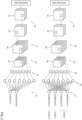
- the present method for detecting anomalies provides for having a multiclass classifier 50 (shown in Figure 3 ), which in the following is referred to as the zone classifier 50, and a plurality of classifiers 70 (one shown in Figure 3 ), which in the following are referred to as the binary classifiers 70, since they are configured to classify on two classes, as is explained in the following.
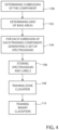
- the zone classifier 50 and the binary classifiers 70 may be trained in the manner described with reference to Figure 4 .
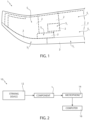
- the training of the zone classifier 50 provides for having a plurality of components identical to the component 1, without deteriorations, and which in the following are referred to as the training components. Furthermore, as is shown in Figure 4 , the training provides for determining (block 100, Figure 4 ) a plurality of portions 2 (visible in Figure 1 ) of the component 1, which in the following are referred to as the subregions 2.
- the component 1 is divided into the subregions 2, each one of which has a respective outer surface S 2 , which in the following is referred to as the subregion surface S 2 .
- the subregions 2 are adjacent to one another and not overlapped, so that, referring to the outer surface S 1 for indicating the overall outer surface of the component 1, each point of the outer surface S 1 belongs to a corresponding subregion surface S 2 .
- the division of the component 1 into the respective subregions 2 may occur, for example, on the basis of the inner structure of the component 1, for example so that, considering any subregion 2 and referring to the cross-sections thereof for indicating the cross-sections of the subregion 2 taken along planes perpendicular to a same direction of reference, such cross-sections are identical to one another. Still by way of mere example, in the case when the component 1 is formed by different lattice structures (not shown) covered by a metal surface, one or more subregions 2 may be delimited so that each one covers a corresponding lattice structure.
- one or more subregions 2 can be delimited depending on the shape of the component 1, for example so that the edges of the subregion 2 coincide with regions where a thickness variation of the component 1 or a camber variation of the outer surface S 1 of the component 1 occurs.
- the criteria adopted for determining the boundaries of the subregions 2 of the component 1 can be different with respect to what described and are irrelevant for the implementation of the present method.
- the training components are identical to the component 1, the division into the subregions 2 is also applied to each training component.
- the subregions 2 are stored in the computer 16 and are for example in a number equal to NUM_SUBREG.
- the outer surface S 1 is divided into a set of respective subportions 6, which in the following are referred to as the base areas 6.
- a grid 8 formed by the base areas 6 (a portion of grid is qualitatively shown in Figure 5 ) is determined (block 102, Figure 4 ); by way of mere example, each base area 6 may have an extension equal to approximately 1cm 2 .
- the grid 8 of base areas 6 extends only on part of the outer surface S 1 of the component 1, the grid 8 of base areas 6 fully covers the outer surface S 1 .
- the base areas 6 are shown as having an approximately square shape and are arranged so as to form a matrix, they may have a different shape, besides shapes different from one another; also the arrangement of the base areas 6 may be different.
- the base areas 6 are comparable to punctiform areas and can be struck individually.
- the grid 8 of base areas 6 also applies to the outer surface of each training component.
- a corresponding plurality of spectrograms (an example is shown in Figure 6 ) is generated (block 104, Figure 4 ) for each one of the subregions 2, as is described in the following.
- the base area 6 is struck (block 200, Figure 7 ) by the striking device 12, so as to generate a corresponding acoustic signal, which is acquired (block 202, Figure 7 ) by means of the microphone 14.
- the acoustic signal extends on a corresponding time interval having a duration T (for example equal to two seconds), identical for all the acoustic signals; furthermore, the base area 6 is struck for example periodically, with a frequency equal to 3Hz.
- the acoustic signals may be acquired in a synchronous manner by striking the respective base areas 6, so that, during each time interval of an acoustic signal, a same number of strikes of the base area 6 takes place; optionally, the time arrangement of the strikes may be the same for all the acoustic signals. In other words, the acoustic signal is acquired during the periodic striking of the base area 6.
- each acoustic signal provides for the sampling (for example, with a precision of sixteen bits per sample) of the acoustic signal with a sampling frequency for example equal to 44kHz. Consequently, in a manner known per se the acquisition of each acoustic signal entails the transduction of the acoustic signal in a corresponding electric signal and the sampling of the electric signal, therefore it entails the generation of a sampled electric signal, whose samples represent corresponding samples of the acoustic signal.
- the computer 16 calculates (block 204, Figure 7 ), for each acquired acoustic signal, the corresponding spectrogram, on the basis of the corresponding sampled electric signal.
- each spectrogram is formed by a value matrix; each row of the spectrogram refers to a corresponding spectral interval (two indicated by ⁇ f 1 and ⁇ f n respectively), whereas each column refers to a corresponding time sub-interval of the time interval on which the acoustic signal extends.
- the time sub-intervals of the time interval on which the acoustic signal extends may have a same duration ⁇ t, for example equal to 40ms; the spectral intervals may be non-uniform, therefore they may be generated on the basis for example of a logarithmic curve, instead of a linear curve.
- each value of the column is indicative of the energy content of the portion of acoustic signal relative to the corresponding time sub-interval that falls within the corresponding spectral interval.
- the values of each column of the spectrogram are equal to the modulus of the samples of the discrete Fourier transform of the samples of the sampled electric signal that fall within the corresponding time sub-interval; it is further possible, in each column of the spectrogram, for each element of the column to be obtained as the result of a numeric filtering of several (for example, three) adjacent samples of the above-mentioned discrete Fourier transform.
- the spectrograms may be the so-called MEL spectrograms.
- the computer 16 stores (block 106, Figure 4 ) the spectrograms and the association present between each spectrogram and the corresponding subregion 2, i.e. the subregion 2 to which the base area 6, which has been struck during the acquisition of the acoustic signal to which the spectrogram refers, belongs.
- the computer 16 stores, for each spectrogram, a corresponding label, which represents a corresponding class which indicates the subregion 2 to which the spectrogram refers.
- the computer 16 trains (block 108, Figure 4 ) the zone classifier 50, on the basis of the spectrograms and of the relative labels, in a supervised manner.
- the zone classifier 50 is a multiclass classifier; for example, the zone classifier 50 is a convolutional neural network, as is shown in Figure 3 .
- the zone classifier 50 comprises a feature extraction stage 52, which includes a sequence of one or more hidden layers; in particular, by way of mere example, Figure 3 shows a first hidden layer and a second hidden layer, indicated by 54 and 54' respectively. Furthermore, both the first and the second hidden layers 54, 54' comprise a respective convolution stage (indicated by 56 and 56' respectively) and a subsequent respective pooling stage (indicated by 58 and 58' respectively).
- the convolution stages 56, 56' are configured to perform, starting from the data present on the respective inputs, convolution, activation and (optionally) normalization operations, on the basis of respective filters, in a manner known per se.
- the convolution stage 56 of the first hidden layer 54 receives at the input single spectrograms
- the convolution stage 56' of the second hidden layer 54' receives at the input the output of the pooling stage 58 of the first hidden layer 54.
- the pooling stages 58, 58' are configured to perform pooling operations on the outputs of the corresponding convolution stages 56, 56'.
- the feature extraction stage 52 further comprises a flatten layer 60, which is configured to perform flattening operations on the output of the pooling stage 58' of the second hidden layer 54'.
- the zone classifier 50 further comprises a fully connected layer 61, shown in a simplified and qualitative manner, which receives the output of the flatten layer 60 and classifies it on a number of classes equal to the number NUM_SUBREG of subregions 2; each class is thus associated with a corresponding subregion 2.
- a number NUM_SUBREG of subregions 2 equal to four was assumed; the four subregions 2 are indicated by SUBREGION A, SUBREGION B, SUBREGION C, SUBREGION D.
- the training of the zone classifier 50 may occur as is shown in Figure 9 .
- the computer 16 selects (block 300, Figure 9 ) a first subset, a second subset and a third subset, which may be disjoined from one another, i.e. may not share any spectrogram.
- a first subset a second subset and a third subset, which may be disjoined from one another, i.e. may not share any spectrogram.
- the computer 16 performs (block 302, Figure 9 ) a training of the zone classifier 50.
- a training occurs in a manner known per se and is of supervised type, as is mentioned in the foregoing.
- the training may provide for iterating sequences of operations of:
- the iteration of the above-mentioned sequences of operations thus ends when the classifications of the validation set respect the stop condition.
- the stop condition may take place when an error function, indicative of the differences between the classifications of the spectrograms of the validation set and the actual classes goes below a pre-established threshold.
- the computer 16 applies (block 304, Figure 9 ) the zone classifier 50, as obtained following the operations mentioned in block 302 (therefore, with the values of the respective parameters as available at the end of the operations mentioned in block 302) to the spectrograms of the test set, so as to classify them.
- the computer 16 calculates (block 306, Figure 9 ) the confusion matrix of the classifications obtained by means of the operations mentioned in block 304.
- the confusion matrix has dimensions NUM_SUBREG x NUM_SUBREG.
- the element CM ij represents the number of spectrograms relative to the i-th subregion 2 classified as relative to the j-th subregion 2, therefore it is indicative of a probability of the zone classifier 50 to confuse the i-th subregion 2 with the j-th subregion 2.
- the computer 16 detects (block 308, Figure 9 ) the possible presence of one or more N-tuples (with N integer greater or equal to two) of classes such that, for each N-tuple, the numbers of spectrograms associated with the classes of the N-tuple that have been classified in a confused manner with respect to one another, i.e. the values of the elements CM ij with 'i' and 'j' different from one another and indicative of classes of the N-tuple, respect an aggregation criterion.
- the computer 16 may analyse the confusion matrix by rows, initially assuming that the classes do not form any N-tuple. That having been said, considering the i-th class (with 'i' assuming in succession the values 1, 2, 3 and 4), the computer 16 detects if the i-th class already belongs to an N-tuple, in which case it increases the value of 'i' by one, so as to analyse the following row, and thus the following class, otherwise, before increasing the value of 'i', the computer 16 checks if there is one or more m-th classes (with 'm' different from ⁇ i') such that CM im > TH (with TH indicating a threshold value), in which case the computer 16 alternatively:
- the criteria for determining the dimensions of the N-tuples and of the classes forming them may vary with respect to what described.
- the confusion matrix may be analysed by the computer 16 in a different manner with respect to what described.
- variations are possible in which the N-tuples of classes are determined assuming that the confusion matrix is in first approximation symmetric, in which case the computer 16 may analyse only a subset of the confusion matrix.
- the computer 16 aggregates (block 310, Figure 9 ) the classes of the N-tuple; in other words, the computer 16 aggregates the subregions 2 (in a number equal to N) associated with the classes of the N-tuple, so as to form a single region (understood as aggregation of subregions), which is associated (block 312, Figure 9 ) by the computer 16 with a corresponding label, i.e. a corresponding class.
- Figure 3 qualitatively shows the aggregation of the classes relative to the SUBREGION A and to the SUBREGION B.
- the computer identifies (block 314, Figure 9 ) a plurality of zones 9 (shown in Figure 4 ) of the component 1, which are stored by the computer 16.
- each subregion 2 that has not been aggregated during the operations mentioned in block 310 forms a corresponding zone 9, which is associated with the label of the subregion 2; furthermore, each set of subregions 2 aggregated to one another forms a corresponding zone 9, which is associated with the label of the aggregation of subregions 2.
- Figure 5 highlights a first zone (indicated by 9'), which coincides with a corresponding subregion 2 which has not undergone any aggregation, and a second zone (indicated by 9"), which coincides with the aggregation of a corresponding pair of subregions 2.
- Figure 3 shows how the aggregation of the classes relative to the SUBREGION A and to the SUBREGION B leads to the definition of a class relative to a ZONE A, whereas the classes of the SUBREGIONS C and D coincide with the classes of a ZONE C and of a ZONE D respectively.
- the aggregation of the classes mentioned in block 310 enables the fully connected layer 61 of the zone classifier 50 to classify on a set of classes equal to the number of zones 9, which in the following is referred to as the number NUM_Z.
- the zone classifier 50 is initially configured to classify on a number of classes (which are also referred to as the subregion classes) equal to the number NUM_SUBREG of subregions 2; following the aggregation of the classes mentioned in block 310, the zone classifier 50 is configured to classify on a number of classes (which are also referred to as the zone classes) equal to the number NUM_Z.
- the zones 9 of the component 1 are regions of the component 1, each one of which generates, when mechanically struck in a respective base area 6, an acoustic signal whose spectrogram can be classified by the zone classifier 50 as relative to an acoustic signal generated by striking a portion of the region.
- the training of the zone classifier 50 is thus ended.
- the computer 16 trains (block 110) the above-mentioned binary classifiers 70, which are in a number equal to NUM_Z; each binary classifier 70 is thus associated with a corresponding zone 9 of the component 1.
- each binary classifier 70 is trained so as to classify spectrograms generated by striking the corresponding zone 9, so that the classification alternatively indicates if the zone 9 is undamaged or damaged.
- the computer 16 selects (block 400, Figure 11 ) the spectrograms of the above-mentioned training set relative to the k-th zone 9, which form a set of first training observations, and furthermore selects the spectrograms of the training set relative to zones 9 different from the k-th zone 9, which form a set of second training observations.
- the acoustic signals coming from zones 9 different from the k-th zone 9 are considered as generated by damaged versions of the k-th zone 9, so as to obviate the difficulty of finding real damaged versions of the k-th zone 9.
- the set of second training observations also, or exclusively, comprises spectrograms obtained starting from acoustic signals generated by one or more damaged versions of the k-th zone 9, i.e. by components in which the k-th zone is damaged, and/or spectrograms obtained starting from acoustic signals generated by one or more damaged versions of w-th zones 9 (with w different from k), i.e. by components in which the w-th zone is damaged.
- the computer 15 selects (block 402, Figure 11 ) the spectrograms of the above-mentioned validation set relative to the k-th zone 9, which form a set of first validation observations, and furthermore selects the spectrograms of the validation set relative to zones 9 different from the k-th zone 9, which form a set of second validation observations.
- the set of second validation observations also, or exclusively, comprises spectrograms obtained starting from acoustic signals generated by one or more damaged versions of the k-the zone 9 and/or by one or more damaged versions of w-th zones 9 (with w different from k), i.e. by components in which the w-th zone is damaged.
- the computer 16 initialises (block 404, Figure 11 ) the binary classifier 70, which, as is shown in Figure 3 , is formed by a convolutional neural network and includes a respective feature extraction stage 72 and at least one fully connected layer 81, which includes two output nodes, associated with the "undamaged zone” class and with the "damaged zone” class respectively.
- the binary classifier 70 is initialised so that the respective feature extraction stage 72 is identical to the feature extraction stage 52 of the zone classifier 50.
- the feature extraction stage 72 of the binary classifier 70 has the same structure of the feature extraction stage 52 of the zone classifier 50; furthermore, the initial values of the parameters (i.e. of the weights and of the biases of the filters) of the feature extraction stage 72 of the binary classifier 70 are equal to the values of the corresponding parameters of the feature extraction stage 52 of the zone classifier 50.
- the fully connected layer 81 of the binary classifier 70 may be initialised in a manner known per se, irrespective of the fully connected layer 61 of the zone classifier 50.
- the binary classifiers 70 are initialised in an identical manner, irrespective of the zones 9 of the component 1 to which they refer.
- the computer 16 trains (block 406, Figure 11 ) the binary classifier 70, associating with the first training and validation observations a first class, indicative of the fact that the spectrogram relates to an undamaged version of the zone to which the binary classifier 70 refers, and associating with the second training and validation observations a second class, indicative of the fact that the spectrogram relates to a damaged version of the zone to which the binary classifier 70 refers.
- the training enables the feature extraction stage 72 of the binary classifier 70 to differentiate the values of the respective parameters from the values of the parameters of the feature extraction stage 52 of the zone classifier 50.
- the Applicant observed that, by initialising the binary classifiers 70 as is described in the foregoing, it is possible to improve the relative performances, with regard to the actual capability to distinguish between an undamaged zone and a damaged zone. Variations are anyway possible in which the binary classifiers 70 are initialised in a manner known per se, irrespective of the zone classifier 50.
- zone classifier 50 and the binary classifiers 70 have been trained, it is possible to use the detection system 10 for detecting the possible presence of anomalies in an unknown component of the same type of the component 1, but of which it is not known a priori if it is undamaged or damaged. To such end, the operations shown in Figure 12 are performed.
- the striking device 12 is actuated so as to strike (block 500, Figure 12 ) a base area 6 of the unknown component, which in the following is referred to as the unknown area, so as to generate a corresponding acoustic signal which is acquired (block 502, Figure 12 ) by the computer 16 through the microphone 14; on the basis of the acquired acoustic signal, the computer 16 calculates (block 504, Figure 12 ) the corresponding spectrogram, which in the following is referred to as the unknown spectrogram, since the state (undamaged/damaged) of the unknown area is not known a priori; furthermore, in the following reference is made to the unknown zone to refer to the zone 9 of the unknown component to which the unknown area belongs.
- the computer 16 applies (block 506, Figure 12 ) to the unknown spectrogram the zone classifier 50, so as to classify the unknown zone.
- the zone classifier 50 allows identifying, between the zones 9 of the component 1, the zone 9 that corresponds to the unknown zone.
- the computer 16 selects (block 507, Figure 12 ), between the binary classifiers 70, the binary classifier 70 relative to the identified zone.
- the computer 16 applies (block 508, Figure 12 ) to the unknown spectrogram the selected binary classifier 70, which alternatively classifies the unknown spectrogram as i) belonging to the respective first class, which indicates that the unknown spectrogram relates to an acoustic signal generated by striking an undamaged version of the identified zone 9, or as belonging to the respective second class, which indicates that the unknown spectrogram relates to an acoustic signal generated by striking a damaged version of the identified zone 9.
- the computer 16 detects (block 510, Figure 12 ) the presence of an anomaly, i.e. of a damage/deterioration, in the unknown zone of the unknown component; in such case, in a manner known per se the computer 16 may generate a corresponding signalling.
- an anomaly i.e. of a damage/deterioration
- the zone 9 is undamaged; alternatively, if one or more of the spectrograms relative to the zone 9 of the unknown component have been classified as belonging to the respective second class, the zone is damaged.
- the present method allows automating the detection of anomalies of aircraft mechanical components, as well as localising possible anomalies at the level of single zones of the mechanical components. Still, the present method allows excluding the presence of a trained operator.
- the zone classifier and/or the binary classifiers can be formed by classifiers of different type with respect to what described.
- the grid 8 of base areas 6, and thus the definition of the shape and of the arrangement of the areas which are hit by the striking device 12 is the same for the component 1, the training components and the unknown component
- the grid of base areas of one or more of the training components, as well of the unknown component it is possible for the grid of base areas of one or more of the training components, as well of the unknown component, to differ from the grid 8 of base areas 6 of the component 1.
- the detection system 10 is configured so that the operations mentioned in block 500 are carried out on an unknown area of which the zone of belonging is known a priori, it is possible to omit the operations mentioned in block 506.
- the unknown spectrogram is not classified by the zone classifier 50, but is classified only by the binary classifier 70 relative to the zone to which the unknown area belongs, which is selected by the computer 16 depending on the zone of belonging.
- binary classifiers 70 may be trained without being previously initialised on the basis of the zone classifier 50.
- the detection and aggregation operations of the N-tuple of classes mentioned in blocks 308, 310 are optional.
- the zone classifier 50 is configured to classify on a number of classes equal to NUM_SUBREG, and furthermore the number of binary classifiers 70 is equal to NUM_SUBREG. This entails an increase in the number of binary classifiers 70 and therefore an increase in the computational burden required for training them.
- the computer 16 may perform so-called denoising operations, i.e. noise filtering operations, of the sampled electric signals deriving from the transduction of the acoustic signals, in which case the spectrograms are calculated on the basis of the sampled electric signals available after the filtering of the noise.
- denoising operations i.e. noise filtering operations
- the computer 16 may perform standardisation operations of the spectrograms and for the operations described in the foregoing to be performed starting from the standardised spectrograms.
- the computer 16 may calculate the mean and the standard deviation of the elements of the spectrograms relative to the training components, and subsequently may subtract the mean from each one of such spectrograms, besides from the unknown spectrograms; furthermore, the computer 16 may divide the elements of the spectrograms relative to the training components and the unknown spectrograms for the standard deviation.
- Other types of standardisation or normalisation are anyway possible.
- the present method and the present system for detecting anomalies can also be applied to mechanical components different from the aircraft mechanical components; for example, they can be applied for structurally monitoring a wind blade or a civil infrastructure, and more generally for monitoring the health status of any whatsoever mechanical piece.
Landscapes
- Physics & Mathematics (AREA)
- Engineering & Computer Science (AREA)
- Health & Medical Sciences (AREA)
- Life Sciences & Earth Sciences (AREA)
- General Physics & Mathematics (AREA)
- General Health & Medical Sciences (AREA)
- Analytical Chemistry (AREA)
- Pathology (AREA)
- Immunology (AREA)
- Biochemistry (AREA)
- Chemical & Material Sciences (AREA)
- Signal Processing (AREA)
- Evolutionary Computation (AREA)
- Artificial Intelligence (AREA)
- Theoretical Computer Science (AREA)
- Acoustics & Sound (AREA)
- Biophysics (AREA)
- Software Systems (AREA)
- Mathematical Physics (AREA)
- General Engineering & Computer Science (AREA)
- Computing Systems (AREA)
- Molecular Biology (AREA)
- Data Mining & Analysis (AREA)
- Computational Linguistics (AREA)
- Biomedical Technology (AREA)
- Measurement Of Mechanical Vibrations Or Ultrasonic Waves (AREA)
Priority Applications (4)
| Application Number | Priority Date | Filing Date | Title |
|---|---|---|---|
| EP22209811.3A EP4375657B1 (de) | 2022-11-28 | 2022-11-28 | Verfahren und system zur erkennung von anomalien von mechanischen komponenten, insbesondere flugzeugkomponenten, durch klassifizierung von spektrogrammen von akustischen signalen |
| CN202380082019.2A CN120344852A (zh) | 2022-11-28 | 2023-11-23 | 通过对声学信号的频谱图进行分类来检测机械部件、特别是飞行器部件的异常的方法和系统 |
| KR1020257021294A KR20250112878A (ko) | 2022-11-28 | 2023-11-23 | 음향 신호의 스펙트로그램 분류를 통한 기계 부품, 특히 항공기 부품의 이상 감지 방법 및 시스템 |
| PCT/IB2023/061847 WO2024116035A1 (en) | 2022-11-28 | 2023-11-23 | Method and system for detecting anomalies of mechanical components, in particular aircraft components, by classifying spectrograms of acoustic signals |
Applications Claiming Priority (1)
| Application Number | Priority Date | Filing Date | Title |
|---|---|---|---|
| EP22209811.3A EP4375657B1 (de) | 2022-11-28 | 2022-11-28 | Verfahren und system zur erkennung von anomalien von mechanischen komponenten, insbesondere flugzeugkomponenten, durch klassifizierung von spektrogrammen von akustischen signalen |
Publications (2)
| Publication Number | Publication Date |
|---|---|
| EP4375657A1 true EP4375657A1 (de) | 2024-05-29 |
| EP4375657B1 EP4375657B1 (de) | 2025-12-10 |
Family
ID=84923228
Family Applications (1)
| Application Number | Title | Priority Date | Filing Date |
|---|---|---|---|
| EP22209811.3A Active EP4375657B1 (de) | 2022-11-28 | 2022-11-28 | Verfahren und system zur erkennung von anomalien von mechanischen komponenten, insbesondere flugzeugkomponenten, durch klassifizierung von spektrogrammen von akustischen signalen |
Country Status (4)
| Country | Link |
|---|---|
| EP (1) | EP4375657B1 (de) |
| KR (1) | KR20250112878A (de) |
| CN (1) | CN120344852A (de) |
| WO (1) | WO2024116035A1 (de) |
Citations (1)
| Publication number | Priority date | Publication date | Assignee | Title |
|---|---|---|---|---|
| US20080144927A1 (en) * | 2006-12-14 | 2008-06-19 | Matsushita Electric Works, Ltd. | Nondestructive inspection apparatus |
-
2022
- 2022-11-28 EP EP22209811.3A patent/EP4375657B1/de active Active
-
2023
- 2023-11-23 WO PCT/IB2023/061847 patent/WO2024116035A1/en not_active Ceased
- 2023-11-23 KR KR1020257021294A patent/KR20250112878A/ko active Pending
- 2023-11-23 CN CN202380082019.2A patent/CN120344852A/zh active Pending
Patent Citations (1)
| Publication number | Priority date | Publication date | Assignee | Title |
|---|---|---|---|---|
| US20080144927A1 (en) * | 2006-12-14 | 2008-06-19 | Matsushita Electric Works, Ltd. | Nondestructive inspection apparatus |
Non-Patent Citations (1)
| Title |
|---|
| FUJII HIROMITSU ET AL: "Defect detection with estimation of material condition using ensemble learning for hammering test", 2016 IEEE INTERNATIONAL CONFERENCE ON ROBOTICS AND AUTOMATION (ICRA), IEEE, 16 May 2016 (2016-05-16), pages 3847 - 3854, XP032908643, [retrieved on 20160608], DOI: 10.1109/ICRA.2016.7487573 * |
Also Published As
| Publication number | Publication date |
|---|---|
| CN120344852A (zh) | 2025-07-18 |
| WO2024116035A1 (en) | 2024-06-06 |
| EP4375657B1 (de) | 2025-12-10 |
| KR20250112878A (ko) | 2025-07-24 |
Similar Documents
| Publication | Publication Date | Title |
|---|---|---|
| EP3460611B1 (de) | System und verfahren zur flugzeugfehlererkennung | |
| Meng et al. | Health indicator of bearing constructed by rms-CUMSUM and GRRMD-CUMSUM with multifeatures of envelope spectrum | |
| CN112991579B (zh) | 一种基于生成对抗网络的直升机动部件异常检测方法 | |
| CN111881723B (zh) | 雷电地闪回击波形的自动识别方法、系统及电子设备 | |
| US8433539B2 (en) | Wind turbine monitoring device, method, and program | |
| CN115130499B (zh) | 基于振动信号的变工况下轴承保持架打滑率在线测量及预测方法 | |
| CN116257777B (zh) | 分类模型融合的密封继电器多余物检测与材质识别方法 | |
| CN110988985B (zh) | 基于波形特征的地震信号检测方法 | |
| CN114004091A (zh) | 一种基于CEEMDAN-BNs的风力变桨距系统故障诊断方法 | |
| CN115077685A (zh) | 设备状态检测方法、装置及系统 | |
| US20050144537A1 (en) | Method to use a receiver operator characteristics curve for model comparison in machine condition monitoring | |
| Tian et al. | An ensemble learning-based fault diagnosis method for rotating machinery | |
| US8271233B2 (en) | Method of multi-level fault isolation design | |
| US12528597B2 (en) | Method and system for detecting anomalies relating to components of a transmission system of an aircraft, in particular a helicopter | |
| CN114091334A (zh) | 基于改进蝙蝠算法和支持向量机的局部放电故障诊断方法 | |
| CN117009791B (zh) | 一种航空发动机的故障识别方法及系统 | |
| EP4375657A1 (de) | Verfahren und system zur erkennung von anomalien von mechanischen komponenten, insbesondere flugzeugkomponenten, durch klassifizierung von spektrogrammen von akustischen signalen | |
| CN115856818B (zh) | 基于不确定性和数据拒判的雷达目标分类方法 | |
| CN115512716B (zh) | 用于识别车辆异响的方法、设备和系统 | |
| KR20120022126A (ko) | 신경 회로망을 이용한 부분 방전 자동 분석 시스템 | |
| CN117192482B (zh) | 基于信号分选的靶机平台侦察设备告警方法 | |
| Slimene et al. | Anomaly Detection Method of Aircraft System using Multivariate Time Series Clustering and Classification Techniques | |
| CN119105469A (zh) | 远程诊断电动汽车的动力系统故障的方法 | |
| Vagnoli et al. | A machine learning classifier for condition monitoring and damage detection of bridge infrastructure | |
| KR102692620B1 (ko) | 신경망 기반의 전자기 펄스 분류 방법 |
Legal Events
| Date | Code | Title | Description |
|---|---|---|---|
| PUAI | Public reference made under article 153(3) epc to a published international application that has entered the european phase |
Free format text: ORIGINAL CODE: 0009012 |
|
| STAA | Information on the status of an ep patent application or granted ep patent |
Free format text: STATUS: REQUEST FOR EXAMINATION WAS MADE |
|
| 17P | Request for examination filed |
Effective date: 20231009 |
|
| AK | Designated contracting states |
Kind code of ref document: A1 Designated state(s): AL AT BE BG CH CY CZ DE DK EE ES FI FR GB GR HR HU IE IS IT LI LT LU LV MC ME MK MT NL NO PL PT RO RS SE SI SK SM TR |
|
| GRAP | Despatch of communication of intention to grant a patent |
Free format text: ORIGINAL CODE: EPIDOSNIGR1 |
|
| STAA | Information on the status of an ep patent application or granted ep patent |
Free format text: STATUS: GRANT OF PATENT IS INTENDED |
|
| INTG | Intention to grant announced |
Effective date: 20250625 |
|
| P01 | Opt-out of the competence of the unified patent court (upc) registered |
Free format text: CASE NUMBER: UPC_APP_6557_4375657/2025 Effective date: 20250910 |
|
| GRAS | Grant fee paid |
Free format text: ORIGINAL CODE: EPIDOSNIGR3 |
|
| GRAA | (expected) grant |
Free format text: ORIGINAL CODE: 0009210 |
|
| STAA | Information on the status of an ep patent application or granted ep patent |
Free format text: STATUS: THE PATENT HAS BEEN GRANTED |
|
| AK | Designated contracting states |
Kind code of ref document: B1 Designated state(s): AL AT BE BG CH CY CZ DE DK EE ES FI FR GB GR HR HU IE IS IT LI LT LU LV MC ME MK MT NL NO PL PT RO RS SE SI SK SM TR |
|
| REG | Reference to a national code |
Ref country code: CH Ref legal event code: F10 Free format text: ST27 STATUS EVENT CODE: U-0-0-F10-F00 (AS PROVIDED BY THE NATIONAL OFFICE) Effective date: 20251210 Ref country code: GB Ref legal event code: FG4D |
|
| REG | Reference to a national code |
Ref country code: DE Ref legal event code: R096 Ref document number: 602022026517 Country of ref document: DE Ref country code: IE Ref legal event code: FG4D |
|
| REG | Reference to a national code |
Ref country code: CH Ref legal event code: R17 Free format text: ST27 STATUS EVENT CODE: U-0-0-R10-R17 (AS PROVIDED BY THE NATIONAL OFFICE) Effective date: 20260109 |
|
| PG25 | Lapsed in a contracting state [announced via postgrant information from national office to epo] |
Ref country code: ES Free format text: LAPSE BECAUSE OF FAILURE TO SUBMIT A TRANSLATION OF THE DESCRIPTION OR TO PAY THE FEE WITHIN THE PRESCRIBED TIME-LIMIT Effective date: 20251210 |
|
| REG | Reference to a national code |
Ref country code: LT Ref legal event code: MG9D |
|
| PG25 | Lapsed in a contracting state [announced via postgrant information from national office to epo] |
Ref country code: NO Free format text: LAPSE BECAUSE OF FAILURE TO SUBMIT A TRANSLATION OF THE DESCRIPTION OR TO PAY THE FEE WITHIN THE PRESCRIBED TIME-LIMIT Effective date: 20260310 |
|
| PG25 | Lapsed in a contracting state [announced via postgrant information from national office to epo] |
Ref country code: FI Free format text: LAPSE BECAUSE OF FAILURE TO SUBMIT A TRANSLATION OF THE DESCRIPTION OR TO PAY THE FEE WITHIN THE PRESCRIBED TIME-LIMIT Effective date: 20251210 Ref country code: HR Free format text: LAPSE BECAUSE OF FAILURE TO SUBMIT A TRANSLATION OF THE DESCRIPTION OR TO PAY THE FEE WITHIN THE PRESCRIBED TIME-LIMIT Effective date: 20251210 |
|
| REG | Reference to a national code |
Ref country code: NL Ref legal event code: MP Effective date: 20251210 |
|
| PG25 | Lapsed in a contracting state [announced via postgrant information from national office to epo] |
Ref country code: RS Free format text: LAPSE BECAUSE OF FAILURE TO SUBMIT A TRANSLATION OF THE DESCRIPTION OR TO PAY THE FEE WITHIN THE PRESCRIBED TIME-LIMIT Effective date: 20260310 |
|
| PG25 | Lapsed in a contracting state [announced via postgrant information from national office to epo] |
Ref country code: LV Free format text: LAPSE BECAUSE OF FAILURE TO SUBMIT A TRANSLATION OF THE DESCRIPTION OR TO PAY THE FEE WITHIN THE PRESCRIBED TIME-LIMIT Effective date: 20251210 |