EP4375574A1 - Combustor panel, and combustor for gas turbine - Google Patents
Combustor panel, and combustor for gas turbine Download PDFInfo
- Publication number
- EP4375574A1 EP4375574A1 EP22861404.6A EP22861404A EP4375574A1 EP 4375574 A1 EP4375574 A1 EP 4375574A1 EP 22861404 A EP22861404 A EP 22861404A EP 4375574 A1 EP4375574 A1 EP 4375574A1
- Authority
- EP
- European Patent Office
- Prior art keywords
- panel
- flow path
- combustor
- fin
- fins
- Prior art date
- Legal status (The legal status is an assumption and is not a legal conclusion. Google has not performed a legal analysis and makes no representation as to the accuracy of the status listed.)
- Pending
Links
Images




Classifications
-
- F—MECHANICAL ENGINEERING; LIGHTING; HEATING; WEAPONS; BLASTING
- F23—COMBUSTION APPARATUS; COMBUSTION PROCESSES
- F23R—GENERATING COMBUSTION PRODUCTS OF HIGH PRESSURE OR HIGH VELOCITY, e.g. GAS-TURBINE COMBUSTION CHAMBERS
- F23R3/00—Continuous combustion chambers using liquid or gaseous fuel
- F23R3/002—Wall structures
-
- F—MECHANICAL ENGINEERING; LIGHTING; HEATING; WEAPONS; BLASTING
- F02—COMBUSTION ENGINES; HOT-GAS OR COMBUSTION-PRODUCT ENGINE PLANTS
- F02C—GAS-TURBINE PLANTS; AIR INTAKES FOR JET-PROPULSION PLANTS; CONTROLLING FUEL SUPPLY IN AIR-BREATHING JET-PROPULSION PLANTS
- F02C7/00—Features, components parts, details or accessories, not provided for in, or of interest apart form groups F02C1/00 - F02C6/00; Air intakes for jet-propulsion plants
- F02C7/12—Cooling of plants
- F02C7/16—Cooling of plants characterised by cooling medium
- F02C7/18—Cooling of plants characterised by cooling medium the medium being gaseous, e.g. air
-
- F—MECHANICAL ENGINEERING; LIGHTING; HEATING; WEAPONS; BLASTING
- F23—COMBUSTION APPARATUS; COMBUSTION PROCESSES
- F23R—GENERATING COMBUSTION PRODUCTS OF HIGH PRESSURE OR HIGH VELOCITY, e.g. GAS-TURBINE COMBUSTION CHAMBERS
- F23R3/00—Continuous combustion chambers using liquid or gaseous fuel
- F23R3/005—Combined with pressure or heat exchangers
-
- F—MECHANICAL ENGINEERING; LIGHTING; HEATING; WEAPONS; BLASTING
- F23—COMBUSTION APPARATUS; COMBUSTION PROCESSES
- F23R—GENERATING COMBUSTION PRODUCTS OF HIGH PRESSURE OR HIGH VELOCITY, e.g. GAS-TURBINE COMBUSTION CHAMBERS
- F23R3/00—Continuous combustion chambers using liquid or gaseous fuel
- F23R3/42—Continuous combustion chambers using liquid or gaseous fuel characterised by the arrangement or form of the flame tubes or combustion chambers
- F23R3/60—Support structures; Attaching or mounting means
-
- F—MECHANICAL ENGINEERING; LIGHTING; HEATING; WEAPONS; BLASTING
- F23—COMBUSTION APPARATUS; COMBUSTION PROCESSES
- F23R—GENERATING COMBUSTION PRODUCTS OF HIGH PRESSURE OR HIGH VELOCITY, e.g. GAS-TURBINE COMBUSTION CHAMBERS
- F23R2900/00—Special features of, or arrangements for continuous combustion chambers; Combustion processes therefor
- F23R2900/03041—Effusion cooled combustion chamber walls or domes
-
- F—MECHANICAL ENGINEERING; LIGHTING; HEATING; WEAPONS; BLASTING
- F23—COMBUSTION APPARATUS; COMBUSTION PROCESSES
- F23R—GENERATING COMBUSTION PRODUCTS OF HIGH PRESSURE OR HIGH VELOCITY, e.g. GAS-TURBINE COMBUSTION CHAMBERS
- F23R2900/00—Special features of, or arrangements for continuous combustion chambers; Combustion processes therefor
- F23R2900/03042—Film cooled combustion chamber walls or domes
-
- F—MECHANICAL ENGINEERING; LIGHTING; HEATING; WEAPONS; BLASTING
- F23—COMBUSTION APPARATUS; COMBUSTION PROCESSES
- F23R—GENERATING COMBUSTION PRODUCTS OF HIGH PRESSURE OR HIGH VELOCITY, e.g. GAS-TURBINE COMBUSTION CHAMBERS
- F23R2900/00—Special features of, or arrangements for continuous combustion chambers; Combustion processes therefor
- F23R2900/03043—Convection cooled combustion chamber walls with means for guiding the cooling air flow
-
- F—MECHANICAL ENGINEERING; LIGHTING; HEATING; WEAPONS; BLASTING
- F23—COMBUSTION APPARATUS; COMBUSTION PROCESSES
- F23R—GENERATING COMBUSTION PRODUCTS OF HIGH PRESSURE OR HIGH VELOCITY, e.g. GAS-TURBINE COMBUSTION CHAMBERS
- F23R2900/00—Special features of, or arrangements for continuous combustion chambers; Combustion processes therefor
- F23R2900/03044—Impingement cooled combustion chamber walls or subassemblies
-
- F—MECHANICAL ENGINEERING; LIGHTING; HEATING; WEAPONS; BLASTING
- F23—COMBUSTION APPARATUS; COMBUSTION PROCESSES
- F23R—GENERATING COMBUSTION PRODUCTS OF HIGH PRESSURE OR HIGH VELOCITY, e.g. GAS-TURBINE COMBUSTION CHAMBERS
- F23R2900/00—Special features of, or arrangements for continuous combustion chambers; Combustion processes therefor
- F23R2900/03045—Convection cooled combustion chamber walls provided with turbolators or means for creating turbulences to increase cooling
Definitions
- the present disclosure relates to a combustor panel and a gas turbine combustor.
- Patent Document 1 discloses a gas turbine combustor that includes a combustor liner that mixes and burns combustion gas and compressed air.
- the combustor liner is composed of a double-layered combustor panel having an outer wall portion and an inner wall portion. An inner surface of the inner wall portion opposite to the outer wall portion is exposed to a combustion gas and becomes hot. Therefore, a flow path through which cooling air flows is formed between the outer wall portion and the inner wall portion.
- a heat dissipation pin is provided between the inner wall portion and the outer wall portion. The heat dissipation pin protrudes from an outer surface of the inner wall portion toward the outer wall portion. The heat dissipation pin improves the cooling effect of the cooling air flowing within the flow path by transferring heat from the inner surface of the inner wall portion exposed to high temperatures into the flow path and increasing the heat release area in the flow path.
- the present disclosure has been made to solve the above-described problems and an object thereof is to provide a combustor panel and a gas turbine combustor capable of improving the cooling effect of cooling air.
- a combustor panel includes: a first panel; a second panel which is facing the first panel to define a flow path, through which cooling air flows, between the first panel and the second panel, a gas path surface which is allowed to be brought into contact with combustion gas is formed on a surface of the second panel opposite to the flow path; and a plurality of streamlined fins which are formed between the first panel and the second panel in the flow path so as to be arranged at intervals from each other, and each of which has a front edge at an upstream side in a flow direction of the cooling air and a rear edge at a downstream side in the flow direction, wherein each of the fins is formed such that a dimension in a width direction intersecting both of the flow direction and a direction in which the first panel and the second panel face each other is increased towards the first panel from the second panel.
- a gas turbine combustor according to the present disclosure includes a combustor liner formed by the combustor panel.
- the cooling effect of cooling air can be improved.
- the gas turbine 1 of this embodiment is used as an aircraft engine. As shown in FIG. 1 , the gas turbine 1 includes a compressor 4, a combustor (gas turbine combustor) 19, and a turbine 11.
- the compressor 4 generates compressed air A1 by compressing air taken from an intake duct 5.
- the compressor 4 includes a compressor casing 6, a compressor rotor shaft 7, a compressor rotor blade stage 8, and a compressor stator blade stage 9.
- the compressor casing 6 covers the compressor rotor shaft 7 from the outer peripheral side and extends in a direction in which an axis O extends (hereinafter, referred to as the direction of the axis O).
- a plurality of the compressor rotor blade stages 8 are provided in the compressor rotor shaft 7. These compressor rotor blade stages 8 are arranged at intervals in the direction of the axis O.
- Each of the plurality of compressor rotor blade stages 8 includes a plurality of compressor rotor blades 8a.
- the compressor rotor blades 8a extend in a direction along the radius of a virtual circle centered on the axis O (hereinafter, referred to as the radial direction).
- the compressor rotor blades 8a of each compressor rotor blade stage 8 are arranged on the outer peripheral surface of the compressor rotor shaft 7 in a direction centered on the axis O (hereinafter, referred to as the circumferential direction).
- a plurality of the compressor stator blade stages 9 are provided in the compressor casing 6. These compressor stator blade stages 9 are arranged at intervals in the direction of the axis O. The compressor stator blade stages 9 are arranged alternately with the compressor rotor blade stages 8 in the direction of the axis O. Each of the plurality of compressor stator blade stages 9 includes a plurality of compressor stator blades 9a. The compressor stator blades 9a of each compressor stator blade stage 9 are arranged in the circumferential direction on the inner peripheral surface of the compressor casing 6.
- the combustor 19 is disposed inside a combustion chamber 10 provided between the compressor casing 6 and the turbine casing 13 of the turbine 11.
- the combustor 19 generates a combustion gas G by mixing and burning fuel F in the compressed air A1 generated by the compressor 4.
- the combustion gas G generated by the combustor 19 is supplied to the turbine 11.
- the detailed configuration of the combustion chamber 10 and the combustor 19 will be described later.
- the turbine 11 is driven by the combustion gas G having a high temperature and a high pressure generated by the combustion chamber 10. More specifically, the turbine 11 converts the thermal energy of the combustion gas G into rotational energy by expanding the combustion gas G having a high temperature and a high pressure.
- the turbine 11 includes a turbine casing 13, a turbine rotor shaft 12, a turbine rotor blade stage 14, and a turbine stator blade stage 15.
- the turbine casing 13 covers the turbine rotor shaft 12 from the outside in the radial direction.
- the turbine casing 13, the compressor casing 6, and the combustion chamber 10 are integrally connected along the axis O.
- the compressor casing 6, the combustion chamber 10, and the turbine casing 13 constitute a gas turbine casing 2.
- the turbine rotor shaft 12 extends in the direction of the axis O.
- the turbine rotor shaft 12 and the compressor rotor shaft 7 are arranged in the direction of the axis O and are immovable relative to each other.
- the turbine rotor shaft 12 and the compressor rotor shaft 7 constitute a gas turbine rotor shaft 3.
- the gas turbine rotor shaft 3 is integrally rotatable around the axis O within the gas turbine casing 2.
- a plurality of the turbine rotor blade stages 14 are provided on the outer peripheral surface of the turbine rotor shaft 12 at intervals in the direction of the axis O.
- Each of the plurality of turbine rotor blade stages 14 includes a plurality of turbine rotor blades 14a.
- the plurality of turbine rotor blades 14a of one turbine rotor blade stage 14 are arranged at equal intervals in the circumferential direction.
- a plurality of the turbine stator blade stages 15 are provided on the inner peripheral surface of the turbine casing 13 at intervals in the direction of the axis O.
- the plurality of turbine stator blade stages 15 are alternately arranged with the turbine rotor blade stages 14 in the direction of the axis O.
- Each of the turbine stator blade stages 15 includes a plurality of turbine stator blades 15a.
- the turbine stator blades 15a provided in each turbine stator blade stage 15 are arranged on the inner peripheral surface of the turbine casing 13 at equal intervals in the circumferential direction.
- the compressor rotor shaft 7 is rotationally driven by an external drive source. As the compressor rotor shaft 7 rotates, external air is sequentially compressed to generate the compressed air A1.
- the compressed air A1 is supplied into the combustion chamber 10 through the compressor casing 6.
- the compressed air A1 is mixed with the fuel F by the combustor 19 and then burned to generate high-temperature and high-pressure combustion gas G.
- the combustion gas G is supplied into the turbine 11 through the turbine casing 13.
- the combustion gas G sequentially collides with the turbine rotor blade stage 14 and the turbine stator blade stage 15 to apply a rotational driving force to the turbine rotor shaft 12.
- the rotational energy is mainly used to drive the compressor 4.
- the combustion gas G driven the turbine 11 has its flow velocity increased by an exhaust nozzle 16 to become a jet that generates thrust, and is discharged to the outside from the injection port 17.
- the combustion chamber 10 covers part of the turbine rotor shaft 12, which is closed to the compressor 4 more than the turbine rotor blade stage 14 and the turbine stator blade stage 15 in the direction of the axis O, from the radial outer side.
- the combustion chamber 10 forms an annular shape around the turbine rotor shaft 12.
- the combustor 19 includes a combustor liner 20 and a fuel supply nozzle 21.
- the combustor liner 20 is a so-called annular liner formed in an annular shape around the turbine rotor shaft 12.
- the fuel supply nozzle 21 is connected to the end of the combustor liner 20 on the side of the compressor 4 in the direction of the axis O.
- a plurality of the fuel supply nozzles 21 are connected to the annular combustor liner 20 in the circumferential direction at predetermined intervals.
- the fuel F is supplied from the outside into a combustion area S1 within the combustor liner 20 through the fuel supply nozzle 21.
- a swirler 22 is provided around each fuel supply nozzle 21.
- the swirler 22 guides the compressed air A1, supplied from the compressor 4, into the combustion area S 1 from the vicinity of the fuel supply nozzle 21 and provides a swirling flow to generate the combustion gas G in which the fuel F and the compressed air A1 are mixed (see FIG. 1 ).
- the combustor liner 20 includes an inner wall portion 23 and an outer wall portion 24.
- the inner wall portion 23 is formed in an annular shape which covers the turbine rotor shaft 12 from the outside in the radial direction.
- the outer wall portion 24 is formed in an annular shape which further covers the inner wall portion 23 from the outside in the radial direction.
- a space sandwiched in the radial direction by the inner wall portion 23 and the outer wall portion 24 is the combustion area S1 of the combustor liner 20.
- the inner wall portion 23 and the outer wall portion 24 are composed of a plurality of combustor panels 30.
- Each combustor panel 30 has the same configuration. However, the combustor panel 30 of the outer wall portion 24 is formed in a rectangular plate shape extending in the direction of the axis O (see FIG. 1 ), whereas the combustor panel 30 of the inner wall portion 23 is formed to extend along the outer peripheral surface of the gas turbine rotor shaft 3 in the direction of the axis O. In this embodiment, the combustor panel 30 of the inner wall portion 23 is formed by bending the combustor panel 30 of the outer wall portion 24 radially outward at the intermediate portion in the direction of the axis O. The inner wall portion 23 and the outer wall portion 24 are formed by connecting both edges of the plurality of combustor panels 30 in the short direction to form an annular shape.
- one combustor panel 30 constituting the outer wall portion 24 will be described and descriptions of the combustor panels 30 on the outer wall portion 24 and the combustor panels 30 on the inner wall 23 will be omitted.
- the long direction of the combustor panel 30 is referred to as the length direction D1
- the short direction of the combustor panel 30 is referred to as the width direction D2 (see FIG. 4 )
- the direction orthogonal to the length direction D1 and the width direction D2 is referred to as the height direction D3.
- the length direction D1 is along the direction of the axis O.
- the width direction D2 is along the circumferential direction.
- the height direction D3 is along the radial direction.
- the combustor panel 30 includes a first panel 31, a second panel 32, and a fin 40.
- the combustor panel 30 has a double wall cooling structure formed by the first panel 31 and the second panel 32 that are arranged to face each other in the height direction D3. That is, the direction in which the first panel 31 and the second panel 32 face each other is orthogonal to the width direction D2.
- the first panel 31 is formed into a rectangular plate shape extending in the direction of the axis O.
- the first panel 31 is disposed on the side opposite to the combustion area S1 with the second panel 32 interposed there between.
- An impingement cooling hole 33 is formed at an end of the first panel 31 on one side of the length direction D1.
- the end of the first panel 31 on one side of the length direction D1 is an end of the first panel 31 on the side of the compressor 4 in the direction of the axis O (see FIG. 1 ).
- the impingement cooling hole 33 penetrates the first panel 31 in the height direction D3.
- the impingement cooling hole 33 has a perfect circular cross-sectional shape.
- the second panel 32 is formed to have the same shape and dimensions as the first panel 31.
- the second panel 32 extends in the direction of the axis O.
- the second panel 32 is disposed closer to the combustion area S1 than the first panel 31.
- the second panel 32 and the first panel 31 define a flow path S2 through which the cooling air A2 flows.
- a surface of the second panel 32 opposite to the flow path S2 is a gas path surface 35 that is allowed be brought into contact with the combustion gas G.
- An effusion cooling hole 36 is formed at an end of the second panel 32 on the other side of the length direction D1.
- the end of the second panel 32 on the other side of the length direction D1 is the end of the second panel 32 on the side of the turbine 11 in the direction of the axis O (see FIG. 1 ).
- the effusion cooling hole 36 is provided at a position overlapping the impingement cooling hole 33 in the width direction D2.
- the effusion cooling hole 36 penetrates the second panel 32.
- the effusion cooling hole 36 extends linearly toward the impingement cooling hole 33 in the length direction D1 as it goes toward the combustion area S1 in the height direction D3. In this way, the effusion cooling hole 36 is inclined with respect to the length direction D1.
- the cross-sectional shape of the effusion cooling hole 36 is an ellipse whose major axis direction coincides with the length direction D1.
- the cooling air A2 flows in the flow path S2 along the length direction D1 and is discharged from the flow path S2 to the combustion area S1 through the effusion cooling hole 36.
- a direction along a line connecting the center point of the impingement cooling hole 33 and the center point of the effusion cooling hole 36 when viewed from the height direction D3 along the surface of the second panel 32 on the side opposite to the gas path surface 35 in the flow direction of the cooling air A2 is referred to as the flow direction.
- the flow direction in this embodiment coincides with the length direction D1.
- the side on which the cooling air A2 flows is simply referred to as the upstream side, and the opposite side is referred to as the downstream side.
- the fins 40 are formed between the first panel 31 and the second panel 32 in the flow path S2.
- a plurality of the fins 40 are formed at intervals in the length direction D1 and the width direction D2.
- the fins 40 are formed to have a streamlined shape.
- the fin 40 includes a fin main body 43 and a protrusion 44.
- the fin main body 43 is formed in an elliptical shape of which a major axis direction coincides with the length direction D1 when viewed from the height direction D3. Both edges of the fin main body 43 in the length direction D1 extend linearly in the height direction D3 when viewed from the width direction D2.
- the protrusions 44 are provided at both ends of the fin main body 43 in the length direction D1. However, in the fin 40 which is located on the most upstream side of the plurality of fins 40 arranged in the length direction D1, the protrusion 44 is provided only at the downstream end of the fin main body 43.
- the protrusion 44 has a tapered shape in which the dimension in the width direction D2 gradually decreases as it is separated from the fin main body 43 in the length direction D1 when viewed from the height direction D3. When viewed from the height direction D3, the outer edge of the protrusion 44 is smoothly connected to the outer edge of the fin main body 43.
- the end of the protrusion 44 on the side opposite to the fin main body 43 in the direction of the axis O is formed into a rounded shape.
- the fin 40 is formed in a streamlined shape in which the dimension of the width direction D2 gradually increases towards the center portion in the flow direction from the upstream side and the dimension of the width direction D2 gradually decreases towards the downstream side from the center portion in the flow direction when viewed from the height direction D3.
- the upstream protrusion 44 is referred to as a front protrusion 44a and the downstream protrusion 44 is referred to as a rear protrusion 44b.
- the upstream edge of the front protrusion 44a is a front edge 40a of the fin 40 and the downstream edge of the rear protrusion 44b is a rear edge 40b of the fin 40.
- the front edge 40a is linearly inclined to extend toward the upstream side from the second panel 32 to the first panel 31 in the height direction D3, when it is viewed from the width direction D2.
- the upstream edge of the fin main body 43 is the front edge 40a of the fin 40.
- the front edge 40a extends to be perpendicular to the surface of the second panel 32.
- the rear edge 40b is linearly inclined to extend toward the downstream side from the second panel 32 to the first panel 31 in the height direction D3, when it is viewed from the width direction D2.
- the dimension L of the fin 40 in the flow direction is increased towards the first panel 31 from the second panel 32 in the height direction D3.
- the dimension of the fin 40 in the width direction D2 increases towards the first panel 31 from the second panel 32 in the height direction D3.
- the plurality of fins 40 includes first fins 41 and second fins 42.
- the first fins 41 are the fins 40 that constitute a first fin group 41A by being arranged at intervals in the width direction D2 at the same position in the flow direction position.
- the second fins 42 are the fins 40 that constitute a second fin group 42A by being arranged at intervals in the width direction D2 at different positions in the flow direction from those of the first fin group 41A.
- the first fin groups 41A and the second fin groups 42A are alternately provided in the flow direction.
- the first fin group 41A and the second fin group 42A which are adjacent to each other in the flow direction are provided such that the first fin 41 and the second fin 42 are shifted from each other in the width direction D2 and overlap each other when viewed from the width direction D2.
- the flow path S2 of the cooling air A2 is defined to have a mesh shape when viewed from the height direction D3 by the fins 40. Specifically, the flow path S2 is defined as below.
- the first fin 41 and the second fin 42 are arranged to overlap each other when viewed from the width direction D2 to define a small flow path S3.
- the small flow path S3 is the flow path S2 defined by a portion of the overlapping portion of the first fin 41 and the second fin 42 in the width direction D2 excluding both edges 40a and 40b in the flow direction.
- the small flow path S3 is formed in a trapezoidal shape of which a dimension in the width direction D2 gradually decreases towards the first panel 31 from the second panel 32 in the height direction D3 when viewed from the flow direction.
- a large flow path S4 is defined between the first fins 41 adjacent to each other in the width direction D2 and between the second fins 42 adjacent to each other in the width direction D2.
- the large flow path S4 is the flow path S2 defined by a portion of the overlapping portion of the first fins 41 in the width direction D2 excluding the overlapping portion of the first fin 41 and the second fin 42 in the width direction D2.
- the large flow path S4 is formed at a position overlapping the center portion of the fin 40 in the flow direction in the width direction D2.
- the most upstream and most downstream large flow paths S4 are formed in the same area as the other large flow path S4 with respect to the fins 40 that overlap in the width direction D2. In this embodiment, the most upstream and most downstream large flow paths S4 are formed so that the dimension in the length direction D1 are the same as those of the other large flow paths S4.
- the large flow path S4 connects the ends in the length direction D1 of two small flow paths S3, adjacent to each other in the width direction D2.
- the large flow path S4 is formed in a trapezoidal shape of which a dimension in the width direction D2 gradually decreases towards the first panel 31 from the second panel 32 in the height direction D3 when viewed from the flow direction.
- the small flow path S3 and the large flow path S4 are defined to be alternately provided in the flow direction. That is, the flow path S2 is defined to meander in the flow direction.
- the first fin 41 and the second fin 42 are formed to have the same shape and dimensions. Therefore, the dimensions of the first fin 41 and the second fin 42 will be collectively described as the dimensions of the fin 40.
- the dimension W1 in the width direction D2 on the side of the second panel 32 is larger than 0 times and equal to or smaller than 2 times the dimension H in the height direction D3 of the flow path S2.
- the dimension H is, for example, 1.00 mm.
- the dimension W2 in the width direction D2 on the side of the second panel 32 is larger than 0 times and equal to or smaller than 2 times the dimension H
- the dimension W3 in the width direction D2 on the side of the first panel 31 is larger than 0 times and equal to or smaller than 2 times the dimension H.
- the dimension W2 is larger than the dimension W3.
- the dimension W2 is, for example, 0.80 mm.
- the dimension W3 is, for example, 0.56 mm.
- the flow path cross-sectional area of the small flow path S3 is constant at each position in the flow direction.
- the flow path cross-sectional area of the large flow path S4 is constant at each position in the flow direction.
- the constant flow path cross-sectional area means that the flow path cross-sectional area in each flow path (each small flow path S3 and each large flow path S4) is within ⁇ 30% of the average value of the flow path cross-sectional area of the flow direction.
- the flow path cross-sectional area of the large flow path S4 is equal to or larger than the flow path cross-sectional area of the small flow path S3 and equal to or smaller than 3 times the flow path cross-sectional area of the small flow path S3.
- the flow path cross-sectional area of the large flow path S4 is, for example, 2 times the flow path cross-sectional area of the small flow path S3.
- a connecting rib (not shown) is provided in the outer peripheral surface of the fin 40 at the connection portion with the first panel 31 and the second panel 32.
- the connecting rib smoothly connects the surfaces of the fin main body 43 and the protrusion 44 to the surface of the first panel 31 or the second panel 32.
- the outer surface of the connecting rib is formed in an arcuate shape that extends inward in cross-sectional view.
- the compressed air A1 flowing on the outside in the radial direction of the first panel 31 is supplied into the combustor panel 30 through the impingement cooling hole 33 due to the differential pressure between the inside and outside of the combustor 19 and becomes the cooling air A2.
- the cooling air A2 is supplied into the flow path S2
- the cooling air collides with the second panel 32 to cool the second panel 32 disposed on the side of the combustion area S1. In this way, so-called impingement cooling is performed.
- the cooling air A2 colliding with the second panel 32 flows along the length direction D1 between the erected fins 40.
- the flow along the length direction D1 of the cooling air A2 will be referred to as a primary flow.
- the cooling air A2 flowing through the large flow path S4 branches into two small flow paths S3 adjacent to each other in the width direction D2.
- the cooling air A2 flowing through two small flow paths S3 adjacent to each other in the width direction D2 joins together in the downstream large flow path S4.
- the cooling air A2 flows in a meandering manner within the combustor panel 30 by flowing from the large flow path S4 to the small flow path S3 and from the small flow path S3 to the large flow path S4. Accordingly, since the flow path S2 becomes long, cooling can be performed with less cooling air A2. That is, the cooling efficiency of the cooling air A2 is improved.
- the fin 40 improves the cooling efficiency of the cooling air A2 flowing through the flow path S2 by transferring the heat on the inner surface side exposed to high temperatures into the flow path S2 and increasing the heat release area of the second panel 32 in the flow path S2.
- Part of the cooling air A2 flowing between the fins 40 is introduced into the effusion cooling hole 36 due to the pressure difference between the flow path S2 and the combustion area S1.
- the cooling air A2 introduced into the effusion cooling hole 36 flows out toward the combustion area S1 by absorbing heat of the second panel 32 while flowing through the long inclined path.
- the cooling air A2 flowing out toward the combustion area S1 flows along the gas path surface 35 of the second panel 32 to form an air film.
- This air film functions to reduce the heat input transferred from the combustion area S1 to the second panel 32. In this way, so-called film cooling is performed.
- composite cooling is performed by combining impingement cooling or film cooling that improves the cooling efficiency by the meandering of the flow path S2, promotes the heat transfer by the fins 40, and improves the cooling efficiency by the inclination of the effusion cooling hole 36.
- the dimension of the fin 40 in the width direction D2 be increased towards the first panel 31 from the second panel 32. Accordingly, the flow path S2 becomes wider as it goes toward the second panel 32 in the direction in which the first panel 31 and the second panel 32 face each other when viewed from the flow direction. Therefore, the secondary flow of the cooling air A2 toward the second panel 32 in the direction in which the first panel 31 and the second panel 32 face each other is suppressed.
- the cooling air A2 flows more easily along the second panel 32, the flow velocity on the side of the second panel 32 can be improved more than on the side of the first panel 31.
- the second panel 32 can be directly cooled by the cooling air A2. Therefore, the cooling effect of the cooling air A2 can be improved.
- the fin 40 is formed in a streamlined shape. Accordingly, the cooling air A2 can be suppressed from separating from the surface of the fin 40.
- the cooling air A2 flows along the surface of the fin 40. Therefore, the combustion heat can be efficiently transferred from the fin 40 to the cooling air A2. Further, the cooling air A2 can be suppressed from separating from the surface of the fin 40. Accordingly, the pressure loss of the cooling air A2 is reduced and the heat exchange amount between the fin 40 and the cooling air A2 can be increased. Thus, the cooling effect of the cooling air A2 can be improved.
- the dimension L of the fin 40 in the flow direction is increased towards the first panel 31 from the second panel 32. Therefore, the flow path S2 on the side of the second panel 32 becomes wider than the flow path S2 on the side of the first panel 31. Accordingly, more cooling air A2 can flow through the flow path S2 on the side of the second panel 32 than the flow path S2 on the side of the first panel 31. Thus, the heat exchange amount between the second panel 32 and the cooling air A2 can be increased. Thus, the cooling effect of the cooling air A2 can be improved.
- the first fin group 41A and the second fin group 42A are alternately provided in the flow direction.
- the first fin group 41A and the second fin group 42A which are adjacent to each other in the flow direction are provided such that the first fin 41 and the second fin 42 are shifted from each other in the width direction D2 and overlap each other when viewed from the width direction D2. Accordingly, the fins 40 can be densely arranged within the flow path S2. Therefore, the heat release area of the fin 40 can be increased.
- the cooling effect of the second panel 32 by the fin 40 can be improved.
- the cooling effect of the cooling air A2 can be improved.
- the flow path cross-sectional area of the small flow path S3 is constant. Accordingly, since it is possible to suppress acceleration or deceleration of the cooling air A2 within the small flow path S3, it is possible to control the flow velocity of the cooling air A2 within the small flow path S3 to be constant. Thus, it is possible to suppress unevenness in the flow rate of the cooling air A2 within the small flow path S3. Therefore, it is possible to suppress unevenness in the cooling effect of the cooling air A2 within the flow path S2.
- the flow path cross-sectional area of the large flow path S4 between the first fins 41 and between the second fins 42 is constant. Accordingly, since it is possible to suppress acceleration or deceleration of the cooling air A2 within the large flow path S4, it is possible to control the flow velocity of the cooling air A2 within the large flow path S4 to be constant. Thus, it is possible to suppress unevenness in the flow rate of the cooling air A2 within the large flow path S4. Therefore, it is possible to suppress unevenness in the cooling effect of the cooling air A2 within the flow path S2.
- the flow path cross-sectional area of the large flow path S4 is equal to or larger than the flow path cross-sectional area of the small flow path S3 and equal to or smaller than 3 times the flow path cross-sectional area of the small flow path S3. Accordingly, it is possible to suppress acceleration or deceleration of the cooling air A2 while flowing between the large flow path S4 and the small flow path S3 and to control the flow velocity to be constant. Therefore, it is possible to suppress unevenness in the cooling effect of the cooling air A2 within the flow path S2.
- a combustor panel 130 and a combustor 119 according to a second embodiment of the present disclosure will be described with reference to FIGS. 8 and 9 .
- the same reference numerals are given to the same components as in the first embodiment, and detailed descriptions are omitted as appropriate.
- the shape and dimension of the fin 140 are different from those of the first embodiment.
- FIG. 9 is a diagram corresponding to FIG. 5 or FIG. 6 of the first embodiment.
- a front edge 140a of the fin 140 is linearly inclined to extend toward the downstream side from the second panel 32 to the first panel 31 in the height direction D3 when viewed from the width direction D2.
- the front edge 140a of the fin 140 located on the most upstream sides extends to be perpendicular to the surface of the second panel 32.
- the rear edge 140b of the fin 140 is linearly inclined to extend toward the upstream side from the second panel 32 to the first panel 31 in the height direction D3 when viewed from the width direction D2.
- the dimension L of the fin 140 in the flow direction decreases from the second panel 32 to the first panel 31 in the height direction D3.
- the gap between the first fins 141 constituting the first fin group 141A in the width direction D2 is narrower than the gap between the first fins 41 of the first embodiment in the width direction D2.
- the gap between the second fins 142 constituting the second fin group 142A in the width direction D2 is narrower than the gap between the second fins 42 of the first embodiment in the width direction D2.
- the center portion of the large flow path S4 in the flow direction is formed in a triangular shape of which a dimension in the width direction D2 gradually decreases from the second panel 32 to the first panel 31 in the height direction D3 when viewed from the flow direction.
- the dimension W1 on the side of the second panel 32 in the width direction D2 is larger than 0 times and equal to or smaller than 1.0 times the dimension H of the flow path S2 in the height direction D3.
- the dimension H is, for example, 1.00 mm.
- the dimension W2 on the side of the second panel 32 in the width direction D2 is equal to or larger than the dimension W1 in the width direction D2 and equal to or smaller than 3 times the dimension W1 in the width direction D2 on the side of the second panel 32 at the center portion of the fin 140 in the flow direction.
- the dimension L of the fin 140 in the flow direction is decreased towards the first panel 31 from the second panel 32. Accordingly, the heat release area of the fin 140 can be increased on the side of the second panel 32 rather than the side of the first panel 31. Thus, the cooling effect of the second panel 32 by the fin 140 can be improved. Thus, the cooling effect of the cooling air A2 can be improved.
- the dimension W1 is larger than 0 and equal to or smaller than the dimension H of the flow path S2 in the height direction D3. Accordingly, the fins 140 can be densely formed. Therefore, since the heat release area of the fin 140 increases, the heat exchange amount increases. Thus, the cooling effect of the cooling air A2 can be improved.
- the combustor liners 20 and 120 are annular liners, the present disclosure is not limited thereto and the combustor liners 20 and 120 may be so-called can-type liners formed in a cylindrical shape.
- the present disclosure is not limited thereto and the flow direction may intersect the length direction D1.
- the present disclosure is not limited thereto and the front edges 40a and 140a and the rear edges 40b and 140b of the fins 40 and 140 may be formed in an arcuate shape that extends inwardly or outwardly when viewed from the width direction D2.
- the second fins 42 and 142 are formed to have the same shape and dimensions as the first fins 41 and 141, the present disclosure is not limited thereto and the second fins 42 and 142 may be formed to have shapes different from the first fins 41 and 141.
- the second fins 42 and 142 may be formed to be smaller than the first fins 41 and 141.
- the second fins 42 and 142 may be formed to be larger than the first fins 41 and 141.
- combustor panels 30 and 130 and the combustors 19 and 119 described in each embodiment are understood, for example, as below.
Landscapes
- Engineering & Computer Science (AREA)
- Chemical & Material Sciences (AREA)
- Combustion & Propulsion (AREA)
- Mechanical Engineering (AREA)
- General Engineering & Computer Science (AREA)
- Turbine Rotor Nozzle Sealing (AREA)
Abstract
Description
- The present disclosure relates to a combustor panel and a gas turbine combustor.
- Priority is claimed on
Japanese Patent Application No. 2021-137029, filed August 25, 2021 -
Patent Document 1 discloses a gas turbine combustor that includes a combustor liner that mixes and burns combustion gas and compressed air. The combustor liner is composed of a double-layered combustor panel having an outer wall portion and an inner wall portion. An inner surface of the inner wall portion opposite to the outer wall portion is exposed to a combustion gas and becomes hot. Therefore, a flow path through which cooling air flows is formed between the outer wall portion and the inner wall portion. A heat dissipation pin is provided between the inner wall portion and the outer wall portion. The heat dissipation pin protrudes from an outer surface of the inner wall portion toward the outer wall portion. The heat dissipation pin improves the cooling effect of the cooling air flowing within the flow path by transferring heat from the inner surface of the inner wall portion exposed to high temperatures into the flow path and increasing the heat release area in the flow path. -
Japanese Unexamined Patent Application, First Publication No. 2013-104307 - However, in the gas turbine combustor described in
Patent Document 1, when the cooling air is introduced into the flow path from the outer wall portion toward the inner wall portion, the cooling air receives a reaction force from the inner wall portion and a secondary flow is formed in which the cooling air moves away from the inner wall portion. Therefore, the cooling air cannot flow along the inner wall portion, and the expected cooling effect may not be obtained in some cases. - The present disclosure has been made to solve the above-described problems and an object thereof is to provide a combustor panel and a gas turbine combustor capable of improving the cooling effect of cooling air.
- In order to achieve the aforementioned objects, a combustor panel according to the present disclosure includes: a first panel; a second panel which is facing the first panel to define a flow path, through which cooling air flows, between the first panel and the second panel, a gas path surface which is allowed to be brought into contact with combustion gas is formed on a surface of the second panel opposite to the flow path; and a plurality of streamlined fins which are formed between the first panel and the second panel in the flow path so as to be arranged at intervals from each other, and each of which has a front edge at an upstream side in a flow direction of the cooling air and a rear edge at a downstream side in the flow direction, wherein each of the fins is formed such that a dimension in a width direction intersecting both of the flow direction and a direction in which the first panel and the second panel face each other is increased towards the first panel from the second panel.
- A gas turbine combustor according to the present disclosure includes a combustor liner formed by the combustor panel.
- According to the combustor panel and the gas turbine combustor of the present disclosure, the cooling effect of cooling air can be improved.
-
-
FIG. 1 is a cross-sectional view showing a schematic configuration of an aircraft gas turbine according to a first embodiment of the present disclosure when taken along an axis. -
FIG. 2 is a cross-sectional view showing a schematic configuration of a combustor liner according to the first embodiment of the present disclosure when taken along an axis. -
FIG. 3 is a cross-sectional view showing a schematic configuration of a combustor panel according to the first embodiment of the present disclosure where it is sectioned in a length direction. -
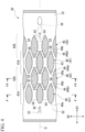
FIG. 4 is a plan view showing a schematic configuration of a second panel according to the first embodiment of the present disclosure when viewed in a height direction. -
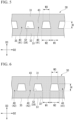
FIG. 5 is a cross-sectional view taken along a line V-V ofFIG. 4 . -
FIG. 6 is a cross-sectional view taken along a line VI-VI ofFIG. 4 . -
FIG. 7 is an enlarged view of a part VII inFIG. 3 . -
FIG. 8 is a cross-sectional view showing a schematic configuration of a combustor panel according to a second embodiment of the present disclosure where it is sectioned in a length direction. -
FIG. 9 is a cross-sectional view showing a schematic configuration of the combustor panel according to the second embodiment of the present disclosure when viewed in a flow direction. - Hereinafter, a
gas turbine 1 according to a first embodiment of the present disclosure will be described in detail with reference toFIGS. 1 to 7 . - The
gas turbine 1 of this embodiment is used as an aircraft engine. As shown inFIG. 1 , thegas turbine 1 includes acompressor 4, a combustor (gas turbine combustor) 19, and a turbine 11. - The
compressor 4 generates compressed air A1 by compressing air taken from anintake duct 5. Thecompressor 4 includes acompressor casing 6, acompressor rotor shaft 7, a compressorrotor blade stage 8, and a compressorstator blade stage 9. Thecompressor casing 6 covers thecompressor rotor shaft 7 from the outer peripheral side and extends in a direction in which an axis O extends (hereinafter, referred to as the direction of the axis O). - A plurality of the compressor
rotor blade stages 8 are provided in thecompressor rotor shaft 7. These compressorrotor blade stages 8 are arranged at intervals in the direction of the axis O. Each of the plurality of compressorrotor blade stages 8 includes a plurality ofcompressor rotor blades 8a. Thecompressor rotor blades 8a extend in a direction along the radius of a virtual circle centered on the axis O (hereinafter, referred to as the radial direction). Thecompressor rotor blades 8a of each compressorrotor blade stage 8 are arranged on the outer peripheral surface of thecompressor rotor shaft 7 in a direction centered on the axis O (hereinafter, referred to as the circumferential direction). - A plurality of the compressor
stator blade stages 9 are provided in thecompressor casing 6. These compressorstator blade stages 9 are arranged at intervals in the direction of the axis O. The compressorstator blade stages 9 are arranged alternately with the compressorrotor blade stages 8 in the direction of the axis O. Each of the plurality of compressorstator blade stages 9 includes a plurality ofcompressor stator blades 9a. Thecompressor stator blades 9a of each compressorstator blade stage 9 are arranged in the circumferential direction on the inner peripheral surface of thecompressor casing 6. - The
combustor 19 is disposed inside acombustion chamber 10 provided between thecompressor casing 6 and theturbine casing 13 of the turbine 11. Thecombustor 19 generates a combustion gas G by mixing and burning fuel F in the compressed air A1 generated by thecompressor 4. The combustion gas G generated by thecombustor 19 is supplied to the turbine 11. The detailed configuration of thecombustion chamber 10 and thecombustor 19 will be described later. - The turbine 11 is driven by the combustion gas G having a high temperature and a high pressure generated by the
combustion chamber 10. More specifically, the turbine 11 converts the thermal energy of the combustion gas G into rotational energy by expanding the combustion gas G having a high temperature and a high pressure. The turbine 11 includes aturbine casing 13, aturbine rotor shaft 12, a turbinerotor blade stage 14, and a turbinestator blade stage 15. - The
turbine casing 13 covers theturbine rotor shaft 12 from the outside in the radial direction. Theturbine casing 13, thecompressor casing 6, and thecombustion chamber 10 are integrally connected along the axis O. Thecompressor casing 6, thecombustion chamber 10, and theturbine casing 13 constitute agas turbine casing 2. - The
turbine rotor shaft 12 extends in the direction of the axis O. Theturbine rotor shaft 12 and thecompressor rotor shaft 7 are arranged in the direction of the axis O and are immovable relative to each other. Theturbine rotor shaft 12 and thecompressor rotor shaft 7 constitute a gasturbine rotor shaft 3. The gasturbine rotor shaft 3 is integrally rotatable around the axis O within thegas turbine casing 2. - A plurality of the turbine rotor blade stages 14 are provided on the outer peripheral surface of the
turbine rotor shaft 12 at intervals in the direction of the axis O. Each of the plurality of turbine rotor blade stages 14 includes a plurality ofturbine rotor blades 14a. The plurality ofturbine rotor blades 14a of one turbinerotor blade stage 14 are arranged at equal intervals in the circumferential direction. - A plurality of the turbine stator blade stages 15 are provided on the inner peripheral surface of the
turbine casing 13 at intervals in the direction of the axis O. The plurality of turbine stator blade stages 15 are alternately arranged with the turbine rotor blade stages 14 in the direction of the axis O. Each of the turbine stator blade stages 15 includes a plurality ofturbine stator blades 15a. Theturbine stator blades 15a provided in each turbinestator blade stage 15 are arranged on the inner peripheral surface of theturbine casing 13 at equal intervals in the circumferential direction. - In operating the
gas turbine 1 configured as described above, first, thecompressor rotor shaft 7 is rotationally driven by an external drive source. As thecompressor rotor shaft 7 rotates, external air is sequentially compressed to generate the compressed air A1. The compressed air A1 is supplied into thecombustion chamber 10 through thecompressor casing 6. In thecombustion chamber 10, the compressed air A1 is mixed with the fuel F by thecombustor 19 and then burned to generate high-temperature and high-pressure combustion gas G. The combustion gas G is supplied into the turbine 11 through theturbine casing 13. - In the turbine 11, the combustion gas G sequentially collides with the turbine
rotor blade stage 14 and the turbinestator blade stage 15 to apply a rotational driving force to theturbine rotor shaft 12. The rotational energy is mainly used to drive thecompressor 4. The combustion gas G driven the turbine 11 has its flow velocity increased by anexhaust nozzle 16 to become a jet that generates thrust, and is discharged to the outside from theinjection port 17. - The
combustion chamber 10 covers part of theturbine rotor shaft 12, which is closed to thecompressor 4 more than the turbinerotor blade stage 14 and the turbinestator blade stage 15 in the direction of the axis O, from the radial outer side. Thecombustion chamber 10 forms an annular shape around theturbine rotor shaft 12. - The
combustor 19 includes acombustor liner 20 and afuel supply nozzle 21. - The
combustor liner 20 is a so-called annular liner formed in an annular shape around theturbine rotor shaft 12. - The
fuel supply nozzle 21 is connected to the end of thecombustor liner 20 on the side of thecompressor 4 in the direction of the axis O. A plurality of thefuel supply nozzles 21 are connected to theannular combustor liner 20 in the circumferential direction at predetermined intervals. The fuel F is supplied from the outside into a combustion area S1 within thecombustor liner 20 through thefuel supply nozzle 21. - As shown in
FIG. 2 , aswirler 22 is provided around eachfuel supply nozzle 21. Theswirler 22 guides the compressed air A1, supplied from thecompressor 4, into thecombustion area S 1 from the vicinity of thefuel supply nozzle 21 and provides a swirling flow to generate the combustion gas G in which the fuel F and the compressed air A1 are mixed (seeFIG. 1 ). - The
combustor liner 20 includes aninner wall portion 23 and anouter wall portion 24. Theinner wall portion 23 is formed in an annular shape which covers theturbine rotor shaft 12 from the outside in the radial direction. Theouter wall portion 24 is formed in an annular shape which further covers theinner wall portion 23 from the outside in the radial direction. A space sandwiched in the radial direction by theinner wall portion 23 and theouter wall portion 24 is the combustion area S1 of thecombustor liner 20. Theinner wall portion 23 and theouter wall portion 24 are composed of a plurality ofcombustor panels 30. - Each
combustor panel 30 has the same configuration. However, thecombustor panel 30 of theouter wall portion 24 is formed in a rectangular plate shape extending in the direction of the axis O (seeFIG. 1 ), whereas thecombustor panel 30 of theinner wall portion 23 is formed to extend along the outer peripheral surface of the gasturbine rotor shaft 3 in the direction of the axis O. In this embodiment, thecombustor panel 30 of theinner wall portion 23 is formed by bending thecombustor panel 30 of theouter wall portion 24 radially outward at the intermediate portion in the direction of the axis O. Theinner wall portion 23 and theouter wall portion 24 are formed by connecting both edges of the plurality ofcombustor panels 30 in the short direction to form an annular shape. - Hereinafter, one
combustor panel 30 constituting theouter wall portion 24 will be described and descriptions of thecombustor panels 30 on theouter wall portion 24 and thecombustor panels 30 on theinner wall 23 will be omitted. - Hereinafter, the long direction of the
combustor panel 30 is referred to as the length direction D1, the short direction of thecombustor panel 30 is referred to as the width direction D2 (seeFIG. 4 ), and the direction orthogonal to the length direction D1 and the width direction D2 is referred to as the height direction D3. The length direction D1 is along the direction of the axis O. The width direction D2 is along the circumferential direction. The height direction D3 is along the radial direction. - As shown in
FIGS. 3 and4 , thecombustor panel 30 includes afirst panel 31, asecond panel 32, and afin 40. Thecombustor panel 30 has a double wall cooling structure formed by thefirst panel 31 and thesecond panel 32 that are arranged to face each other in the height direction D3. That is, the direction in which thefirst panel 31 and thesecond panel 32 face each other is orthogonal to the width direction D2. - The
first panel 31 is formed into a rectangular plate shape extending in the direction of the axis O. Thefirst panel 31 is disposed on the side opposite to the combustion area S1 with thesecond panel 32 interposed there between. - An
impingement cooling hole 33 is formed at an end of thefirst panel 31 on one side of the length direction D1. In this embodiment, the end of thefirst panel 31 on one side of the length direction D1 is an end of thefirst panel 31 on the side of thecompressor 4 in the direction of the axis O (seeFIG. 1 ). Theimpingement cooling hole 33 penetrates thefirst panel 31 in the height direction D3. Theimpingement cooling hole 33 has a perfect circular cross-sectional shape. - part of the compressed air A1 sent from the
compressor 4 to thecombustion chamber 10 is supplied into thecombustor panel 30 through theimpingement cooling hole 33. The compressed air A1 supplied to thecombustor panel 30 becomes cooling air A2 that cools thecombustor panel 30. - The
second panel 32 is formed to have the same shape and dimensions as thefirst panel 31. Thesecond panel 32 extends in the direction of the axis O. Thesecond panel 32 is disposed closer to the combustion area S1 than thefirst panel 31. Thesecond panel 32 and thefirst panel 31 define a flow path S2 through which the cooling air A2 flows. A surface of thesecond panel 32 opposite to the flow path S2 is a gas path surface 35 that is allowed be brought into contact with the combustion gas G. - An
effusion cooling hole 36 is formed at an end of thesecond panel 32 on the other side of the length direction D1. In this embodiment, the end of thesecond panel 32 on the other side of the length direction D1 is the end of thesecond panel 32 on the side of the turbine 11 in the direction of the axis O (seeFIG. 1 ). Theeffusion cooling hole 36 is provided at a position overlapping theimpingement cooling hole 33 in the width direction D2. Theeffusion cooling hole 36 penetrates thesecond panel 32. Theeffusion cooling hole 36 extends linearly toward theimpingement cooling hole 33 in the length direction D1 as it goes toward the combustion area S1 in the height direction D3. In this way, theeffusion cooling hole 36 is inclined with respect to the length direction D1. The cross-sectional shape of theeffusion cooling hole 36 is an ellipse whose major axis direction coincides with the length direction D1. - The cooling air A2 flows in the flow path S2 along the length direction D1 and is discharged from the flow path S2 to the combustion area S1 through the
effusion cooling hole 36. - Hereinafter, a direction along a line connecting the center point of the
impingement cooling hole 33 and the center point of theeffusion cooling hole 36 when viewed from the height direction D3 along the surface of thesecond panel 32 on the side opposite to the gas path surface 35 in the flow direction of the cooling air A2 is referred to as the flow direction. The flow direction in this embodiment coincides with the length direction D1. Further, in the flow direction, the side on which the cooling air A2 flows is simply referred to as the upstream side, and the opposite side is referred to as the downstream side. - As shown in
FIGS. 3 and4 , thefins 40 are formed between thefirst panel 31 and thesecond panel 32 in the flow path S2. A plurality of thefins 40 are formed at intervals in the length direction D1 and the width direction D2. Thefins 40 are formed to have a streamlined shape. Thefin 40 includes a finmain body 43 and aprotrusion 44. - The fin
main body 43 is formed in an elliptical shape of which a major axis direction coincides with the length direction D1 when viewed from the height direction D3. Both edges of the finmain body 43 in the length direction D1 extend linearly in the height direction D3 when viewed from the width direction D2. - The
protrusions 44 are provided at both ends of the finmain body 43 in the length direction D1. However, in thefin 40 which is located on the most upstream side of the plurality offins 40 arranged in the length direction D1, theprotrusion 44 is provided only at the downstream end of the finmain body 43. Theprotrusion 44 has a tapered shape in which the dimension in the width direction D2 gradually decreases as it is separated from the finmain body 43 in the length direction D1 when viewed from the height direction D3. When viewed from the height direction D3, the outer edge of theprotrusion 44 is smoothly connected to the outer edge of the finmain body 43. The end of theprotrusion 44 on the side opposite to the finmain body 43 in the direction of the axis O is formed into a rounded shape. - That is, the
fin 40 is formed in a streamlined shape in which the dimension of the width direction D2 gradually increases towards the center portion in the flow direction from the upstream side and the dimension of the width direction D2 gradually decreases towards the downstream side from the center portion in the flow direction when viewed from the height direction D3. - In one
fin 40, theupstream protrusion 44 is referred to as afront protrusion 44a and thedownstream protrusion 44 is referred to as arear protrusion 44b. The upstream edge of thefront protrusion 44a is afront edge 40a of thefin 40 and the downstream edge of therear protrusion 44b is arear edge 40b of thefin 40. - The
front edge 40a is linearly inclined to extend toward the upstream side from thesecond panel 32 to thefirst panel 31 in the height direction D3, when it is viewed from the width direction D2. However, since thefin 40 located on the most upstream side does not include thefront protrusion 44a, the upstream edge of the finmain body 43 is thefront edge 40a of thefin 40. In this case, thefront edge 40a extends to be perpendicular to the surface of thesecond panel 32. - The
rear edge 40b is linearly inclined to extend toward the downstream side from thesecond panel 32 to thefirst panel 31 in the height direction D3, when it is viewed from the width direction D2. - In this way, the dimension L of the
fin 40 in the flow direction is increased towards thefirst panel 31 from thesecond panel 32 in the height direction D3. - Further, as shown in
FIGS. 5 and 6 , the dimension of thefin 40 in the width direction D2 increases towards thefirst panel 31 from thesecond panel 32 in the height direction D3. - Further, as shown in
FIGS. 3 and4 , the plurality offins 40 includesfirst fins 41 andsecond fins 42. Thefirst fins 41 are thefins 40 that constitute afirst fin group 41A by being arranged at intervals in the width direction D2 at the same position in the flow direction position. Thesecond fins 42 are thefins 40 that constitute asecond fin group 42A by being arranged at intervals in the width direction D2 at different positions in the flow direction from those of thefirst fin group 41A. - The
first fin groups 41A and thesecond fin groups 42A are alternately provided in the flow direction. Thefirst fin group 41A and thesecond fin group 42A which are adjacent to each other in the flow direction are provided such that thefirst fin 41 and thesecond fin 42 are shifted from each other in the width direction D2 and overlap each other when viewed from the width direction D2. - The flow path S2 of the cooling air A2 is defined to have a mesh shape when viewed from the height direction D3 by the
fins 40. Specifically, the flow path S2 is defined as below. - As shown in
FIGS. 3 ,4 , and7 , thefirst fin 41 and thesecond fin 42 are arranged to overlap each other when viewed from the width direction D2 to define a small flow path S3. The small flow path S3 is the flow path S2 defined by a portion of the overlapping portion of thefirst fin 41 and thesecond fin 42 in the width direction D2 excluding bothedges first panel 31 from thesecond panel 32 in the height direction D3 when viewed from the flow direction. - A large flow path S4 is defined between the
first fins 41 adjacent to each other in the width direction D2 and between thesecond fins 42 adjacent to each other in the width direction D2. The large flow path S4 is the flow path S2 defined by a portion of the overlapping portion of thefirst fins 41 in the width direction D2 excluding the overlapping portion of thefirst fin 41 and thesecond fin 42 in the width direction D2. The large flow path S4 is formed at a position overlapping the center portion of thefin 40 in the flow direction in the width direction D2. The most upstream and most downstream large flow paths S4 are formed in the same area as the other large flow path S4 with respect to thefins 40 that overlap in the width direction D2. In this embodiment, the most upstream and most downstream large flow paths S4 are formed so that the dimension in the length direction D1 are the same as those of the other large flow paths S4. - The large flow path S4 connects the ends in the length direction D1 of two small flow paths S3, adjacent to each other in the width direction D2. The large flow path S4 is formed in a trapezoidal shape of which a dimension in the width direction D2 gradually decreases towards the
first panel 31 from thesecond panel 32 in the height direction D3 when viewed from the flow direction. - The small flow path S3 and the large flow path S4 are defined to be alternately provided in the flow direction. That is, the flow path S2 is defined to meander in the flow direction.
- Referring to
FIGS. 5 and 6 , the dimensions of thefin 40 and the flow path S2 will be described. Thefirst fin 41 and thesecond fin 42 are formed to have the same shape and dimensions. Therefore, the dimensions of thefirst fin 41 and thesecond fin 42 will be collectively described as the dimensions of thefin 40. - At the center portion of the
fin 40 in the flow direction, the dimension W1 in the width direction D2 on the side of thesecond panel 32 is larger than 0 times and equal to or smaller than 2 times the dimension H in the height direction D3 of the flow path S2. The dimension H is, for example, 1.00 mm. - At the center portion of the large flow path S4 in the flow direction, the dimension W2 in the width direction D2 on the side of the
second panel 32 is larger than 0 times and equal to or smaller than 2 times the dimension H, and the dimension W3 in the width direction D2 on the side of thefirst panel 31 is larger than 0 times and equal to or smaller than 2 times the dimension H. The dimension W2 is larger than the dimension W3. The dimension W2 is, for example, 0.80 mm. The dimension W3 is, for example, 0.56 mm. - Further, the flow path cross-sectional area of the small flow path S3 is constant at each position in the flow direction. The flow path cross-sectional area of the large flow path S4 is constant at each position in the flow direction. Here, the constant flow path cross-sectional area means that the flow path cross-sectional area in each flow path (each small flow path S3 and each large flow path S4) is within ±30% of the average value of the flow path cross-sectional area of the flow direction.
- Further, the flow path cross-sectional area of the large flow path S4 is equal to or larger than the flow path cross-sectional area of the small flow path S3 and equal to or smaller than 3 times the flow path cross-sectional area of the small flow path S3. The flow path cross-sectional area of the large flow path S4 is, for example, 2 times the flow path cross-sectional area of the small flow path S3.
- A connecting rib (not shown) is provided in the outer peripheral surface of the
fin 40 at the connection portion with thefirst panel 31 and thesecond panel 32. The connecting rib smoothly connects the surfaces of the finmain body 43 and theprotrusion 44 to the surface of thefirst panel 31 or thesecond panel 32. The outer surface of the connecting rib is formed in an arcuate shape that extends inward in cross-sectional view. - Next, the cooling effect of the double wall cooling structure of the
combustor panel 30 will be described with reference toFIGS. 1 to 4 . - The compressed air A1 flowing on the outside in the radial direction of the
first panel 31 is supplied into thecombustor panel 30 through theimpingement cooling hole 33 due to the differential pressure between the inside and outside of thecombustor 19 and becomes the cooling air A2. When the cooling air A2 is supplied into the flow path S2, the cooling air collides with thesecond panel 32 to cool thesecond panel 32 disposed on the side of the combustion area S1. In this way, so-called impingement cooling is performed. - The cooling air A2 colliding with the
second panel 32 flows along the length direction D1 between the erectedfins 40. Hereinafter, the flow along the length direction D1 of the cooling air A2 will be referred to as a primary flow. - The cooling air A2 flowing through the large flow path S4 branches into two small flow paths S3 adjacent to each other in the width direction D2. The cooling air A2 flowing through two small flow paths S3 adjacent to each other in the width direction D2 joins together in the downstream large flow path S4. The cooling air A2 flows in a meandering manner within the
combustor panel 30 by flowing from the large flow path S4 to the small flow path S3 and from the small flow path S3 to the large flow path S4. Accordingly, since the flow path S2 becomes long, cooling can be performed with less cooling air A2. That is, the cooling efficiency of the cooling air A2 is improved. - Further, the
fin 40 improves the cooling efficiency of the cooling air A2 flowing through the flow path S2 by transferring the heat on the inner surface side exposed to high temperatures into the flow path S2 and increasing the heat release area of thesecond panel 32 in the flow path S2. - Part of the cooling air A2 flowing between the
fins 40 is introduced into theeffusion cooling hole 36 due to the pressure difference between the flow path S2 and the combustion area S1. The cooling air A2 introduced into theeffusion cooling hole 36 flows out toward the combustion area S1 by absorbing heat of thesecond panel 32 while flowing through the long inclined path. - Then, the cooling air A2 flowing out toward the combustion area S1 flows along the gas path surface 35 of the
second panel 32 to form an air film. This air film functions to reduce the heat input transferred from the combustion area S1 to thesecond panel 32. In this way, so-called film cooling is performed. - In this way, in this embodiment, composite cooling is performed by combining impingement cooling or film cooling that improves the cooling efficiency by the meandering of the flow path S2, promotes the heat transfer by the
fins 40, and improves the cooling efficiency by the inclination of theeffusion cooling hole 36. - Incidentally, when the cooling air A2 supplied into the flow path S2 collides with the
second panel 32, a secondary flow in which the cooling air A2 is separated from thesecond panel 32 may occur in addition to the primary flow. As the secondary flow increases, thesecond panel 32 exposed to high temperatures cannot be directly cooled, and the cooling effect decreases. - According to this embodiment, the dimension of the
fin 40 in the width direction D2 be increased towards thefirst panel 31 from thesecond panel 32. Accordingly, the flow path S2 becomes wider as it goes toward thesecond panel 32 in the direction in which thefirst panel 31 and thesecond panel 32 face each other when viewed from the flow direction. Therefore, the secondary flow of the cooling air A2 toward thesecond panel 32 in the direction in which thefirst panel 31 and thesecond panel 32 face each other is suppressed. Thus, the cooling air A2 flows more easily along thesecond panel 32, the flow velocity on the side of thesecond panel 32 can be improved more than on the side of thefirst panel 31. Thus, thesecond panel 32 can be directly cooled by the cooling air A2. Therefore, the cooling effect of the cooling air A2 can be improved. - Further, the
fin 40 is formed in a streamlined shape. Accordingly, the cooling air A2 can be suppressed from separating from the surface of thefin 40. The cooling air A2 flows along the surface of thefin 40. Therefore, the combustion heat can be efficiently transferred from thefin 40 to the cooling air A2. Further, the cooling air A2 can be suppressed from separating from the surface of thefin 40. Accordingly, the pressure loss of the cooling air A2 is reduced and the heat exchange amount between thefin 40 and the cooling air A2 can be increased. Thus, the cooling effect of the cooling air A2 can be improved. - In this embodiment, the dimension L of the
fin 40 in the flow direction is increased towards thefirst panel 31 from thesecond panel 32. Therefore, the flow path S2 on the side of thesecond panel 32 becomes wider than the flow path S2 on the side of thefirst panel 31. Accordingly, more cooling air A2 can flow through the flow path S2 on the side of thesecond panel 32 than the flow path S2 on the side of thefirst panel 31. Thus, the heat exchange amount between thesecond panel 32 and the cooling air A2 can be increased. Thus, the cooling effect of the cooling air A2 can be improved. - In this embodiment, the
first fin group 41A and thesecond fin group 42A are alternately provided in the flow direction. Thefirst fin group 41A and thesecond fin group 42A which are adjacent to each other in the flow direction are provided such that thefirst fin 41 and thesecond fin 42 are shifted from each other in the width direction D2 and overlap each other when viewed from the width direction D2. Accordingly, thefins 40 can be densely arranged within the flow path S2. Therefore, the heat release area of thefin 40 can be increased. Thus, the cooling effect of thesecond panel 32 by thefin 40 can be improved. Thus, the cooling effect of the cooling air A2 can be improved. - In this embodiment, the flow path cross-sectional area of the small flow path S3 is constant. Accordingly, since it is possible to suppress acceleration or deceleration of the cooling air A2 within the small flow path S3, it is possible to control the flow velocity of the cooling air A2 within the small flow path S3 to be constant. Thus, it is possible to suppress unevenness in the flow rate of the cooling air A2 within the small flow path S3. Therefore, it is possible to suppress unevenness in the cooling effect of the cooling air A2 within the flow path S2.
- In this embodiment, the flow path cross-sectional area of the large flow path S4 between the
first fins 41 and between thesecond fins 42 is constant. Accordingly, since it is possible to suppress acceleration or deceleration of the cooling air A2 within the large flow path S4, it is possible to control the flow velocity of the cooling air A2 within the large flow path S4 to be constant. Thus, it is possible to suppress unevenness in the flow rate of the cooling air A2 within the large flow path S4. Therefore, it is possible to suppress unevenness in the cooling effect of the cooling air A2 within the flow path S2. - In this embodiment, the flow path cross-sectional area of the large flow path S4 is equal to or larger than the flow path cross-sectional area of the small flow path S3 and equal to or smaller than 3 times the flow path cross-sectional area of the small flow path S3. Accordingly, it is possible to suppress acceleration or deceleration of the cooling air A2 while flowing between the large flow path S4 and the small flow path S3 and to control the flow velocity to be constant. Therefore, it is possible to suppress unevenness in the cooling effect of the cooling air A2 within the flow path S2.
- Hereinafter, a
combustor panel 130 and acombustor 119 according to a second embodiment of the present disclosure will be described with reference toFIGS. 8 and9 . In the second embodiment, the same reference numerals are given to the same components as in the first embodiment, and detailed descriptions are omitted as appropriate. In the second embodiment, the shape and dimension of thefin 140 are different from those of the first embodiment. -
FIG. 9 is a diagram corresponding toFIG. 5 or FIG. 6 of the first embodiment. - As shown in
FIGS. 8 and9 , afront edge 140a of thefin 140 is linearly inclined to extend toward the downstream side from thesecond panel 32 to thefirst panel 31 in the height direction D3 when viewed from the width direction D2. However, thefront edge 140a of thefin 140 located on the most upstream sides extends to be perpendicular to the surface of thesecond panel 32. - The
rear edge 140b of thefin 140 is linearly inclined to extend toward the upstream side from thesecond panel 32 to thefirst panel 31 in the height direction D3 when viewed from the width direction D2. - That is, the dimension L of the
fin 140 in the flow direction decreases from thesecond panel 32 to thefirst panel 31 in the height direction D3. - The gap between the
first fins 141 constituting thefirst fin group 141A in the width direction D2 is narrower than the gap between thefirst fins 41 of the first embodiment in the width direction D2. - The gap between the
second fins 142 constituting thesecond fin group 142A in the width direction D2 is narrower than the gap between thesecond fins 42 of the first embodiment in the width direction D2. - The center portion of the large flow path S4 in the flow direction is formed in a triangular shape of which a dimension in the width direction D2 gradually decreases from the
second panel 32 to thefirst panel 31 in the height direction D3 when viewed from the flow direction. - At the center portion of the
fin 140 in the flow direction, the dimension W1 on the side of thesecond panel 32 in the width direction D2 is larger than 0 times and equal to or smaller than 1.0 times the dimension H of the flow path S2 in the height direction D3. The dimension H is, for example, 1.00 mm. - At the center portion of the large flow path S4 in the flow direction, the dimension W2 on the side of the
second panel 32 in the width direction D2 is equal to or larger than the dimension W1 in the width direction D2 and equal to or smaller than 3 times the dimension W1 in the width direction D2 on the side of thesecond panel 32 at the center portion of thefin 140 in the flow direction. - In this embodiment, the dimension L of the
fin 140 in the flow direction is decreased towards thefirst panel 31 from thesecond panel 32. Accordingly, the heat release area of thefin 140 can be increased on the side of thesecond panel 32 rather than the side of thefirst panel 31. Thus, the cooling effect of thesecond panel 32 by thefin 140 can be improved. Thus, the cooling effect of the cooling air A2 can be improved. - In this embodiment, the dimension W1 is larger than 0 and equal to or smaller than the dimension H of the flow path S2 in the height direction D3. Accordingly, the
fins 140 can be densely formed. Therefore, since the heat release area of thefin 140 increases, the heat exchange amount increases. Thus, the cooling effect of the cooling air A2 can be improved. - Although the embodiments of the present disclosure have been described above in detail with reference to the drawings, the specific configuration is not limited to these embodiments, and includes design changes within the scope of the gist of the present disclosure.
- Furthermore, in the above-described embodiments, although the
combustor liners combustor liners - Furthermore, in the above-described embodiments, although the flow direction coincides with the length direction D1, the present disclosure is not limited thereto and the flow direction may intersect the length direction D1.
- Furthermore, in the above-described embodiments, although the
front edges rear edges fins front edges rear edges fins - Furthermore, in the above-described embodiments, although the
second fins first fins second fins first fins second fins first fins second fins first fins - <Appendix>
- The
combustor panels combustors - (1) The
combustor panels first panel 31; thesecond panel 32 which is facing thefirst panel 31 to define the flow path S2 through which the cooling air A2 flows between thefirst panel 31 and thesecond panel 32 the gas path surface 35 which is allowed to be brought into contact with the combustion gas G is formed on a surface of the second panel opposite to the flow path S2; and the plurality ofstreamlined fins first panel 31 and thesecond panel 32 within the flow path S2 in the flow path S2 so as to be arranged at intervals from each other, and each of which has thefront edges rear edges fins first panel 31 and thesecond panel 32 face each other is increased towards thefirst panel 31 from thesecond panel 32.
Accordingly, the flow path S2 becomes wider toward thesecond panel 32 in the direction in which thefirst panel 31 and thesecond panel 32 face each other when viewed from the flow direction. Therefore, the secondary flow of the cooling air A2 toward thesecond panel 32 in the direction in which thefirst panel 31 and thesecond panel 32 face each other is suppressed. Thus, the cooling air A2 flows more easily along thesecond panel 32. Thus, thesecond panel 32 can be directly cooled by the cooling air A2. Therefore, the cooling effect of the cooling air A2 can be improved. - (2) The
combustor panel 30 of the second aspect is thecombustor panel 30 of (1), wherein the dimension of thefin 40 in the flow direction may be increased towards thefirst panel 31 from thesecond panel 32.
Accordingly, the flow path S2 on the side of thesecond panel 32 becomes wider than the flow path S2 on the side of thefirst panel 31. Therefore, more cooling air A2 can flow through the flow path S2 on the side of thesecond panel 32 than the flow path S2 on the side of thefirst panel 31. Thus, the heat exchange amount between thesecond panel 32 and the cooling air A2 can be increased. - (3) The
combustor panel 130 of the third aspect is thecombustor panel 130 of (1), wherein the dimension of thefin 140 in the flow direction may be decreased towards thefirst panel 31 from thesecond panel 32.
Accordingly, the heat release area of thefin 140 can be increased on the side of thesecond panel 32 rather than the side of thefirst panel 31. Thus, the cooling effect of thesecond panel 32 by thefin 140 can be improved. - (4) The
combustor panels combustor panels fins first fin groups first fins second fin groups second fins first fin groups second fin groups first fin group second fin group first fins second fins
Accordingly, thefins fins second panel 32 by thefins - (5) The
combustor panels combustor panels first fins second fins
Accordingly, it is possible to suppress unevenness in the flow rate of the cooling air A2 within the small flow path S3. Therefore, it is possible to suppress unevenness in the cooling effect of the cooling air A2 within the flow path S2. - (6) The
combustor panels combustor panels first fins second fins
Accordingly, it is possible to suppress unevenness in the flow rate of the cooling air A2 within the large flow path S4. Therefore, it is possible to suppress unevenness in the cooling effect of the cooling air A2 within the flow path S2. - (7) The
combustors combustor liners combustor panels - It is possible to provide the combustor panel and the gas turbine combustor capable of improving the cooling effect of cooling air.
-
- 1 Gas turbine
- 2 Gas turbine casing
- 3 Gas turbine rotor shaft
- 4 Compressor
- 5 Intake duct
- 6 Compressor casing
- 7 Compressor rotor shaft
- 8 Compressor rotor blade stage
- 8a Compressor rotor blade
- 9 Compressor stator blade stage
- 9a Compressor stator blade
- 10 Combustion chamber
- 11 Turbine
- 12 Turbine rotor shaft
- 13 Turbine casing
- 14 Turbine rotor blade stage
- 14a Turbine rotor blade
- 15 Turbine stator blade stage
- 15a Turbine stator blade
- 16 Exhaust nozzle
- 17 Injection port
- 19, 119 Combustor (gas turbine combustor)
- 20, 120 Combustor liner
- 21 Fuel supply nozzle
- 22 Swirler
- 23 Inner wall portion
- 24 Outer wall portion
- 30, 130 Combustor panel
- 31 First panel
- 32 Second panel
- 33 Impingement cooling hole
- 35 Gas path surface
- 36 Effusion cooling hole
- 40, 140 Fin
- 40a, 140a Front edge
- 40b, 140b Rear edge
- 41, 141 First fin
- 41A, 141A First fin group
- 42, 142 Second fin
- 42A, 142A Second fin group
- 43 Fin main body
- 44 Protrusion
- 44a Front protrusion
- 44b Rear protrusion
- A1 Compressed air
- A2 Cooling air
- D1 Length direction
- D2 Width direction
- D3 Height direction
- F Fuel
- G Combustion gas
- O Axis
- S1 Combustion area
- S2 Flow path
- S3 Small flow path
- S4 Large flow path
- L Dimension (of fin in flow direction)
- W1 Dimension (on second panel side in width direction at center portion of flow path in flow direction)
- W2 Dimension (on second panel side in width direction at center portion of large flow path in flow direction)
- W3 Dimension (on first panel side in width direction at center portion of large flow path in flow direction)
- H Dimension (of flow path in height direction)
Claims (7)
- A combustor panel comprising:a first panel;a second panel which is facing the first panel to define a flow path, through which cooling air flows, between the first panel and the second panel, a gas path surface which is allowed to be brought into contact with combustion gas is formed on a surface of the second panel opposite to the flow path; anda plurality of streamlined fins which are formed between the first panel and the second panel in the flow path so as to be arranged at intervals from each other, and each of which has a front edge at an upstream side in a flow direction of the cooling air and a rear edge at a downstream side in the flow direction,wherein each of the fins is formed such that a dimension in a width direction intersecting both of the flow direction and a direction in which the first panel and the second panel face each other is increased towards the first panel from the second panel.
- The combustor panel according to claim 1,
wherein a dimension of the fin in the flow direction is increased towards the first panel from the second panel. - The combustor panel according to claim 1,
wherein a dimension of the fin in the flow direction is decreased towards the first panel from the second panel. - The combustor panel according to any one of claims 1 to 3,
wherein the plurality of fins includes:first fin groups each of which including first fins arranged at intervals in the width direction at a first position in the flow direction; andsecond fin groups each of which including second fins arranged at intervals in the width direction at a second position different from the first position in the flow direction,wherein the first fin groups and the second fin groups are alternately provided in the flow direction, andwherein the first fin group and the second fin group which are adjacent to each other in the flow direction are provided such that the first fin and the second fin are shifted from each other in the width direction and overlap each other when viewed from the width direction. - The combustor panel according to claim 4,wherein the first fins and the second fins are arranged to overlap each other when viewed from the width direction to define a plurality of small flow paths, andwherein each of the small flow paths has a constant flow path cross-sectional area.
- The combustor panel according to claim 4,wherein a plurality of large flow paths are defined between the first fins adjacent to each other in the width direction and between the second fins adjacent to each other in the width direction, andwherein each of the large flow paths has a constant flow path cross-sectional area.
- A gas turbine combustor comprising:
a combustor liner formed by the combustor panel according to any one of claims 1 to 3.
Applications Claiming Priority (2)
| Application Number | Priority Date | Filing Date | Title |
|---|---|---|---|
| JP2021137029A JP7614980B2 (en) | 2021-08-25 | 2021-08-25 | Combustor panel and gas turbine combustor |
| PCT/JP2022/031900 WO2023027116A1 (en) | 2021-08-25 | 2022-08-24 | Combustor panel, and combustor for gas turbine |
Publications (2)
| Publication Number | Publication Date |
|---|---|
| EP4375574A1 true EP4375574A1 (en) | 2024-05-29 |
| EP4375574A4 EP4375574A4 (en) | 2024-12-04 |
Family
ID=85322866
Family Applications (1)
| Application Number | Title | Priority Date | Filing Date |
|---|---|---|---|
| EP22861404.6A Pending EP4375574A4 (en) | 2021-08-25 | 2022-08-24 | COMBUSTION CHAMBER PANEL, AND COMBUSTION CHAMBER FOR A GAS TURBINE |
Country Status (4)
| Country | Link |
|---|---|
| US (1) | US20250129938A1 (en) |
| EP (1) | EP4375574A4 (en) |
| JP (1) | JP7614980B2 (en) |
| WO (1) | WO2023027116A1 (en) |
Families Citing this family (1)
| Publication number | Priority date | Publication date | Assignee | Title |
|---|---|---|---|---|
| JP2024043164A (en) * | 2022-09-16 | 2024-03-29 | 三菱重工航空エンジン株式会社 | heat exchange bulkhead |
Family Cites Families (39)
| Publication number | Priority date | Publication date | Assignee | Title |
|---|---|---|---|---|
| JP2005061725A (en) * | 2003-08-14 | 2005-03-10 | Mitsubishi Heavy Ind Ltd | Heat exchange partition |
| EP1813869A3 (en) | 2006-01-25 | 2013-08-14 | Rolls-Royce plc | Wall elements for gas turbine engine combustors |
| GB2441771B (en) * | 2006-09-13 | 2009-07-08 | Rolls Royce Plc | Cooling arrangement for a component of a gas turbine engine |
| GB2453946B (en) * | 2007-10-23 | 2010-07-14 | Rolls Royce Plc | A Wall Element for use in Combustion Apparatus |
| JP5455962B2 (en) * | 2011-04-06 | 2014-03-26 | 三菱重工業株式会社 | Manufacturing method of cooling structure |
| US8667682B2 (en) * | 2011-04-27 | 2014-03-11 | Siemens Energy, Inc. | Method of fabricating a nearwall nozzle impingement cooled component for an internal combustion engine |
| JP5821550B2 (en) | 2011-11-10 | 2015-11-24 | 株式会社Ihi | Combustor liner |
| JP5834876B2 (en) * | 2011-12-15 | 2015-12-24 | 株式会社Ihi | Impinge cooling mechanism, turbine blade and combustor |
| US10107497B2 (en) * | 2012-10-04 | 2018-10-23 | United Technologies Corporation | Gas turbine engine combustor liner |
| EP2999927B1 (en) * | 2013-05-23 | 2020-01-08 | United Technologies Corporation | Gas turbine engine combustor liner panel |
| US20160123592A1 (en) * | 2013-06-14 | 2016-05-05 | United Technologies Corporation | Gas turbine engine combustor liner panel |
| US10352566B2 (en) * | 2013-06-14 | 2019-07-16 | United Technologies Corporation | Gas turbine engine combustor liner panel |
| US9010125B2 (en) * | 2013-08-01 | 2015-04-21 | Siemens Energy, Inc. | Regeneratively cooled transition duct with transversely buffered impingement nozzles |
| JP6202976B2 (en) * | 2013-10-10 | 2017-09-27 | 三菱日立パワーシステムズ株式会社 | Gas turbine combustor |
| EP3058201B1 (en) * | 2013-10-18 | 2018-07-18 | United Technologies Corporation | Combustor wall having cooling element(s) within a cooling cavity |
| US10240790B2 (en) * | 2013-11-04 | 2019-03-26 | United Technologies Corporation | Turbine engine combustor heat shield with multi-height rails |
| CN106029889A (en) | 2013-11-22 | 2016-10-12 | 德那翠丝有限公司 | Adenovirus expressing immune cell stimulating receptor agonist |
| KR101556532B1 (en) * | 2014-01-16 | 2015-10-01 | 두산중공업 주식회사 | liner, flow sleeve and gas turbine combustor including cooling sleeve |
| US20170003027A1 (en) * | 2014-01-31 | 2017-01-05 | United Technologies Corporation | Gas turbine engine combustor liner panel with synergistic cooling features |
| US10309652B2 (en) * | 2014-04-14 | 2019-06-04 | Siemens Energy, Inc. | Gas turbine engine combustor basket with inverted platefins |
| JP6282184B2 (en) * | 2014-06-19 | 2018-02-21 | 三菱日立パワーシステムズ株式会社 | Heat transfer device and gas turbine combustor including the same |
| US11619387B2 (en) * | 2015-07-28 | 2023-04-04 | Rolls-Royce Corporation | Liner for a combustor of a gas turbine engine with metallic corrugated member |
| JP6429764B2 (en) * | 2015-12-24 | 2018-11-28 | 三菱重工航空エンジン株式会社 | gas turbine |
| US20170191417A1 (en) * | 2016-01-06 | 2017-07-06 | General Electric Company | Engine component assembly |
| US10830448B2 (en) * | 2016-10-26 | 2020-11-10 | Raytheon Technologies Corporation | Combustor liner panel with a multiple of heat transfer augmentors for a gas turbine engine combustor |
| US20200003060A1 (en) * | 2017-01-18 | 2020-01-02 | Siemens Aktiengesellschaft | Turbine element for high pressure drop and heat transfer |
| US10563520B2 (en) * | 2017-03-31 | 2020-02-18 | Honeywell International Inc. | Turbine component with shaped cooling pins |
| US11078847B2 (en) * | 2017-08-25 | 2021-08-03 | Raytheon Technologies Corporation | Backside features with intermitted pin fins |
| US10619852B2 (en) * | 2017-08-25 | 2020-04-14 | United Technologies Corporation | Heat shield with round top pin fins and flat top pin fins for improved manufacturing processes |
| US10670273B2 (en) * | 2017-09-08 | 2020-06-02 | Raytheon Technologies Corporation | Cooling configurations for combustor attachment features |
| KR102050562B1 (en) * | 2017-10-30 | 2020-01-08 | 두산중공업 주식회사 | Combustor and gas turbine comprising the same |
| US12560325B2 (en) * | 2017-12-19 | 2026-02-24 | Rtx Corporation | Apparatus and method for mitigating particulate accumulation on a component of a gas turbine engine |
| US20190186375A1 (en) * | 2017-12-20 | 2019-06-20 | Plasma Igniter, LLC | Plasma-Distributing Structure and Directed Flame Path in a Jet Engine |
| US11739691B2 (en) * | 2018-06-28 | 2023-08-29 | Raytheon Technologies Corporation | Engine component |
| JP7105360B2 (en) * | 2018-07-13 | 2022-07-22 | シーメンス エナジー グローバル ゲゼルシャフト ミット ベシュレンクテル ハフツング ウント コンパニー コマンディートゲゼルシャフト | Airfoils for turbine engines with pins |
| US11156363B2 (en) | 2018-12-07 | 2021-10-26 | Raytheon Technologies Corporation | Dirt tolerant pins for combustor panels |
| GB201900474D0 (en) * | 2019-01-14 | 2019-02-27 | Rolls Royce Plc | A double-wall geometry |
| US11015807B2 (en) * | 2019-01-30 | 2021-05-25 | Pratt & Whitney Canada Corp. | Combustor heat shield cooling |
| KR102377720B1 (en) * | 2019-04-10 | 2022-03-23 | 두산중공업 주식회사 | Liner cooling structure with improved pressure losses and combustor for gas turbine having the same |
-
2021
- 2021-08-25 JP JP2021137029A patent/JP7614980B2/en active Active
-
2022
- 2022-08-24 WO PCT/JP2022/031900 patent/WO2023027116A1/en not_active Ceased
- 2022-08-24 EP EP22861404.6A patent/EP4375574A4/en active Pending
- 2022-08-24 US US18/684,950 patent/US20250129938A1/en active Pending
Also Published As
| Publication number | Publication date |
|---|---|
| US20250129938A1 (en) | 2025-04-24 |
| WO2023027116A1 (en) | 2023-03-02 |
| EP4375574A4 (en) | 2024-12-04 |
| JP2023031503A (en) | 2023-03-09 |
| JP7614980B2 (en) | 2025-01-16 |
Similar Documents
| Publication | Publication Date | Title |
|---|---|---|
| EP2713011B1 (en) | Gas turbine engine components with blade tip cooling | |
| US8523523B2 (en) | Cooling arrangements | |
| US10968755B2 (en) | Cooling structure for vane | |
| US9243506B2 (en) | Methods and systems for cooling a transition nozzle | |
| US9395085B2 (en) | Communicating structure between adjacent combustors and turbine portion and gas turbine | |
| EP3071816B1 (en) | Cooling a multi-walled structure of a turbine engine | |
| US20150059349A1 (en) | Combustor chamber cooling | |
| JP2006189044A (en) | Blade outer air seal assembly and turbine blade shroud assembly | |
| CN106123031B (en) | Mixing system | |
| US10436114B2 (en) | Combustor cooling system | |
| EP2868971B1 (en) | Gas turbine combustor | |
| CN116265810B (en) | Cyclone anti-dilution using shaped cooling grates | |
| EP3181821B1 (en) | Turbulators for improved cooling of gas turbine engine components | |
| EP4375574A1 (en) | Combustor panel, and combustor for gas turbine | |
| US20220127964A1 (en) | Cooling structure for trailing edge of turbine blade | |
| US10655478B2 (en) | Turbine blade and gas turbine | |
| CN113983493B (en) | Gas turbine combustor | |
| JP6934350B2 (en) | gas turbine | |
| US12529324B2 (en) | Turbine static blade, fitting structure, and gas turbine | |
| EP4050192B1 (en) | Ring segment and turbomachine | |
| US12025058B2 (en) | Sealing member and gas turbine | |
| KR20210109310A (en) | Apparatus for cooling liner, combustor and gas turbine comprising the same | |
| US11739647B2 (en) | Turbine blade | |
| US20260043333A1 (en) | Heat-exchanging partition wall | |
| US10612393B2 (en) | System and method for near wall cooling for turbine component |
Legal Events
| Date | Code | Title | Description |
|---|---|---|---|
| STAA | Information on the status of an ep patent application or granted ep patent |
Free format text: STATUS: THE INTERNATIONAL PUBLICATION HAS BEEN MADE |
|
| PUAI | Public reference made under article 153(3) epc to a published international application that has entered the european phase |
Free format text: ORIGINAL CODE: 0009012 |
|
| STAA | Information on the status of an ep patent application or granted ep patent |
Free format text: STATUS: REQUEST FOR EXAMINATION WAS MADE |
|
| 17P | Request for examination filed |
Effective date: 20240220 |
|
| AK | Designated contracting states |
Kind code of ref document: A1 Designated state(s): AL AT BE BG CH CY CZ DE DK EE ES FI FR GB GR HR HU IE IS IT LI LT LU LV MC MK MT NL NO PL PT RO RS SE SI SK SM TR |
|
| A4 | Supplementary search report drawn up and despatched |
Effective date: 20241031 |
|
| DAV | Request for validation of the european patent (deleted) | ||
| DAX | Request for extension of the european patent (deleted) | ||
| RIC1 | Information provided on ipc code assigned before grant |
Ipc: F02C 7/18 20060101ALI20241025BHEP Ipc: F23R 3/42 20060101AFI20241025BHEP |