EP4375542A1 - Control system for controlling an oil level in a gearbox of a vehicle, associated gearbox assembly and vehicle - Google Patents
Control system for controlling an oil level in a gearbox of a vehicle, associated gearbox assembly and vehicle Download PDFInfo
- Publication number
- EP4375542A1 EP4375542A1 EP22209683.6A EP22209683A EP4375542A1 EP 4375542 A1 EP4375542 A1 EP 4375542A1 EP 22209683 A EP22209683 A EP 22209683A EP 4375542 A1 EP4375542 A1 EP 4375542A1
- Authority
- EP
- European Patent Office
- Prior art keywords
- gearbox
- valve
- oil
- control system
- fork
- Prior art date
- Legal status (The legal status is an assumption and is not a legal conclusion. Google has not performed a legal analysis and makes no representation as to the accuracy of the status listed.)
- Granted
Links
Images


Classifications
-
- F—MECHANICAL ENGINEERING; LIGHTING; HEATING; WEAPONS; BLASTING
- F16—ENGINEERING ELEMENTS AND UNITS; GENERAL MEASURES FOR PRODUCING AND MAINTAINING EFFECTIVE FUNCTIONING OF MACHINES OR INSTALLATIONS; THERMAL INSULATION IN GENERAL
- F16H—GEARING
- F16H57/00—General details of gearing
- F16H57/04—Features relating to lubrication or cooling or heating
- F16H57/0409—Features relating to lubrication or cooling or heating characterised by increasing efficiency, e.g. by reducing splash losses
-
- F—MECHANICAL ENGINEERING; LIGHTING; HEATING; WEAPONS; BLASTING
- F16—ENGINEERING ELEMENTS AND UNITS; GENERAL MEASURES FOR PRODUCING AND MAINTAINING EFFECTIVE FUNCTIONING OF MACHINES OR INSTALLATIONS; THERMAL INSULATION IN GENERAL
- F16H—GEARING
- F16H57/00—General details of gearing
- F16H57/04—Features relating to lubrication or cooling or heating
- F16H57/0447—Control of lubricant levels, e.g. lubricant level control dependent on temperature
-
- F—MECHANICAL ENGINEERING; LIGHTING; HEATING; WEAPONS; BLASTING
- F16—ENGINEERING ELEMENTS AND UNITS; GENERAL MEASURES FOR PRODUCING AND MAINTAINING EFFECTIVE FUNCTIONING OF MACHINES OR INSTALLATIONS; THERMAL INSULATION IN GENERAL
- F16H—GEARING
- F16H57/00—General details of gearing
- F16H57/04—Features relating to lubrication or cooling or heating
- F16H57/042—Guidance of lubricant
- F16H57/0421—Guidance of lubricant on or within the casing, e.g. shields or baffles for collecting lubricant, tubes, pipes, grooves, channels or the like
- F16H57/0423—Lubricant guiding means mounted or supported on the casing, e.g. shields or baffles for collecting lubricant, tubes or pipes
-
- F—MECHANICAL ENGINEERING; LIGHTING; HEATING; WEAPONS; BLASTING
- F16—ENGINEERING ELEMENTS AND UNITS; GENERAL MEASURES FOR PRODUCING AND MAINTAINING EFFECTIVE FUNCTIONING OF MACHINES OR INSTALLATIONS; THERMAL INSULATION IN GENERAL
- F16H—GEARING
- F16H57/00—General details of gearing
- F16H57/04—Features relating to lubrication or cooling or heating
- F16H57/0434—Features relating to lubrication or cooling or heating relating to lubrication supply, e.g. pumps; Pressure control
- F16H57/0435—Pressure control for supplying lubricant; Circuits or valves therefor
-
- F—MECHANICAL ENGINEERING; LIGHTING; HEATING; WEAPONS; BLASTING
- F16—ENGINEERING ELEMENTS AND UNITS; GENERAL MEASURES FOR PRODUCING AND MAINTAINING EFFECTIVE FUNCTIONING OF MACHINES OR INSTALLATIONS; THERMAL INSULATION IN GENERAL
- F16H—GEARING
- F16H57/00—General details of gearing
- F16H57/04—Features relating to lubrication or cooling or heating
- F16H57/0434—Features relating to lubrication or cooling or heating relating to lubrication supply, e.g. pumps; Pressure control
- F16H57/0441—Arrangements of pumps
-
- F—MECHANICAL ENGINEERING; LIGHTING; HEATING; WEAPONS; BLASTING
- F16—ENGINEERING ELEMENTS AND UNITS; GENERAL MEASURES FOR PRODUCING AND MAINTAINING EFFECTIVE FUNCTIONING OF MACHINES OR INSTALLATIONS; THERMAL INSULATION IN GENERAL
- F16H—GEARING
- F16H57/00—General details of gearing
- F16H57/04—Features relating to lubrication or cooling or heating
- F16H57/0434—Features relating to lubrication or cooling or heating relating to lubrication supply, e.g. pumps; Pressure control
- F16H57/0446—Features relating to lubrication or cooling or heating relating to lubrication supply, e.g. pumps; Pressure control the supply forming part of the transmission control unit, e.g. for automatic transmissions
-
- F—MECHANICAL ENGINEERING; LIGHTING; HEATING; WEAPONS; BLASTING
- F16—ENGINEERING ELEMENTS AND UNITS; GENERAL MEASURES FOR PRODUCING AND MAINTAINING EFFECTIVE FUNCTIONING OF MACHINES OR INSTALLATIONS; THERMAL INSULATION IN GENERAL
- F16H—GEARING
- F16H57/00—General details of gearing
- F16H57/04—Features relating to lubrication or cooling or heating
- F16H57/045—Lubricant storage reservoirs, e.g. reservoirs in addition to a gear sump for collecting lubricant in the upper part of a gear case
-
- F—MECHANICAL ENGINEERING; LIGHTING; HEATING; WEAPONS; BLASTING
- F16—ENGINEERING ELEMENTS AND UNITS; GENERAL MEASURES FOR PRODUCING AND MAINTAINING EFFECTIVE FUNCTIONING OF MACHINES OR INSTALLATIONS; THERMAL INSULATION IN GENERAL
- F16H—GEARING
- F16H57/00—General details of gearing
- F16H57/04—Features relating to lubrication or cooling or heating
- F16H57/0457—Splash lubrication
-
- F—MECHANICAL ENGINEERING; LIGHTING; HEATING; WEAPONS; BLASTING
- F16—ENGINEERING ELEMENTS AND UNITS; GENERAL MEASURES FOR PRODUCING AND MAINTAINING EFFECTIVE FUNCTIONING OF MACHINES OR INSTALLATIONS; THERMAL INSULATION IN GENERAL
- F16H—GEARING
- F16H63/00—Control outputs from the control unit to change-speed- or reversing-gearings for conveying rotary motion or to other devices than the final output mechanism
- F16H63/02—Final output mechanisms therefor; Actuating means for the final output mechanisms
- F16H63/30—Constructional features of the final output mechanisms
- F16H63/32—Gear shift yokes, e.g. shift forks
-
- F—MECHANICAL ENGINEERING; LIGHTING; HEATING; WEAPONS; BLASTING
- F16—ENGINEERING ELEMENTS AND UNITS; GENERAL MEASURES FOR PRODUCING AND MAINTAINING EFFECTIVE FUNCTIONING OF MACHINES OR INSTALLATIONS; THERMAL INSULATION IN GENERAL
- F16H—GEARING
- F16H63/00—Control outputs from the control unit to change-speed- or reversing-gearings for conveying rotary motion or to other devices than the final output mechanism
- F16H2063/005—Preassembled gear shift units for mounting on gear case
-
- F—MECHANICAL ENGINEERING; LIGHTING; HEATING; WEAPONS; BLASTING
- F16—ENGINEERING ELEMENTS AND UNITS; GENERAL MEASURES FOR PRODUCING AND MAINTAINING EFFECTIVE FUNCTIONING OF MACHINES OR INSTALLATIONS; THERMAL INSULATION IN GENERAL
- F16H—GEARING
- F16H2200/00—Transmissions for multiple ratios
- F16H2200/003—Transmissions for multiple ratios characterised by the number of forward speeds
- F16H2200/006—Transmissions for multiple ratios characterised by the number of forward speeds the gear ratios comprising eight forward speeds
-
- F—MECHANICAL ENGINEERING; LIGHTING; HEATING; WEAPONS; BLASTING
- F16—ENGINEERING ELEMENTS AND UNITS; GENERAL MEASURES FOR PRODUCING AND MAINTAINING EFFECTIVE FUNCTIONING OF MACHINES OR INSTALLATIONS; THERMAL INSULATION IN GENERAL
- F16H—GEARING
- F16H2200/00—Transmissions for multiple ratios
- F16H2200/0082—Transmissions for multiple ratios characterised by the number of reverse speeds
- F16H2200/0086—Transmissions for multiple ratios characterised by the number of reverse speeds the gear ratios comprising two reverse speeds
-
- F—MECHANICAL ENGINEERING; LIGHTING; HEATING; WEAPONS; BLASTING
- F16—ENGINEERING ELEMENTS AND UNITS; GENERAL MEASURES FOR PRODUCING AND MAINTAINING EFFECTIVE FUNCTIONING OF MACHINES OR INSTALLATIONS; THERMAL INSULATION IN GENERAL
- F16H—GEARING
- F16H3/00—Toothed gearings for conveying rotary motion with variable gear ratio or for reversing rotary motion
- F16H3/02—Toothed gearings for conveying rotary motion with variable gear ratio or for reversing rotary motion without gears having orbital motion
- F16H3/08—Toothed gearings for conveying rotary motion with variable gear ratio or for reversing rotary motion without gears having orbital motion exclusively or essentially with continuously meshing gears, that can be disengaged from their shafts
- F16H3/087—Toothed gearings for conveying rotary motion with variable gear ratio or for reversing rotary motion without gears having orbital motion exclusively or essentially with continuously meshing gears, that can be disengaged from their shafts characterised by the disposition of the gears
- F16H3/091—Toothed gearings for conveying rotary motion with variable gear ratio or for reversing rotary motion without gears having orbital motion exclusively or essentially with continuously meshing gears, that can be disengaged from their shafts characterised by the disposition of the gears including a single countershaft
- F16H3/0915—Toothed gearings for conveying rotary motion with variable gear ratio or for reversing rotary motion without gears having orbital motion exclusively or essentially with continuously meshing gears, that can be disengaged from their shafts characterised by the disposition of the gears including a single countershaft with coaxial input and output shafts
-
- F—MECHANICAL ENGINEERING; LIGHTING; HEATING; WEAPONS; BLASTING
- F16—ENGINEERING ELEMENTS AND UNITS; GENERAL MEASURES FOR PRODUCING AND MAINTAINING EFFECTIVE FUNCTIONING OF MACHINES OR INSTALLATIONS; THERMAL INSULATION IN GENERAL
- F16H—GEARING
- F16H37/00—Combinations of mechanical gearings, not provided for in groups F16H1/00 - F16H35/00
- F16H37/02—Combinations of mechanical gearings, not provided for in groups F16H1/00 - F16H35/00 comprising essentially only toothed or friction gearings
- F16H37/04—Combinations of toothed gearings only
- F16H37/042—Combinations of toothed gearings only change gear transmissions in group arrangement
- F16H37/046—Combinations of toothed gearings only change gear transmissions in group arrangement with an additional planetary gear train, e.g. creep gear, overdrive
Definitions
- the disclosure relates generally to the field of gearbox lubrication, especially for road vehicles.
- the disclosure relates to a control system for controlling an oil level in a gearbox of a vehicle, to a gearbox assembly comprising such a control system and to a vehicle comprising such a gearbox assembly.
- the disclosure can be applied in heavy-duty vehicles, such as trucks, buses, and construction equipment.
- gearboxes for example for road vehicles such as trucks or buses
- the lubrication and cooling of the gears are usually accomplished with an oil sump where the gears of the countershaft dip into the oil.
- the gear wheels of the countershaft also transport oil to the gear wheels on the main shaft.
- the oil itself is cooled by convection of heat to the gearbox housing and, in some trucks, cooled with a transmission cooler through which the oil is pumped.
- the oil sump lubrication/cooling is a significant source of transmission losses.
- a notable part of the load-independent losses in the transmission are due to the countershaft rotating in the oil sump, commonly referred to as "churning losses”.
- the invention aims at providing a control system for controlling an oil level in a gearbox of a vehicle, such control system being reliable and robust.
- the control system comprises a supply line, which is configured to be connected to a pressurized upstream oil supply of the gearbox, a return line, which is configured to be connected to the supply line, a first valve and a second valve.
- the first valve is configured to be controlled by a first fork of the gearbox, and to switch between an open position and a closed position, according to a position of the first fork.
- the second valve is configured to be controlled by a second fork of the gearbox, the second fork being different from the first fork.
- the second valve is configured to switch between an open position and a closed position, according to a position of the second fork.
- a first end of the return line is connected to the supply line through the first valve and the second valve, the first and second valves being arranged in serial, the first and second valves being both in the open position when the first and second forks are together in a direct drive configuration that engages the direct drive gear selection of the gearbox, so that the return line is pressurized when both valves are open and when the supply line is pressurized.
- the control system comprises a flow control unit, which is connected to a second end of the return line and which is configured to lower the oil level in an oil sump of the gearbox when the return line is pressurized.
- control system allows controlling the oil level of the oil sump by using only mechanical and hydraulic components, which are robust and more reliable than electronic or electro-mechanic components. Furthermore, in case of dysfunction of any component of the control system, the oil level in the oil sump remains at the same level as when the gearbox is not in the direct drive gear selection, which prevents potential damage to the gearbox.
- the first valve and the second valve are both piston valves.
- a technical benefit may include an improved reliability compared to other types of valve.
- the flow control unit comprises a third valve, which is different from the first and second valves and which is in a closed position when the return line is pressurized, whereas the third valve is configured to prevent oil from a filling circuit to fill the oil sump when the third valve is in the closed position.
- control system comprises an oil reservoir, which is connected to the return line and which is filled by oil flowing through the supply line and the return line when the first and second valves are both in an open position
- flow control unit comprises a dump valve, which is arranged between the reservoir and the oil sump of the gearbox, so that oil contained in the reservoir flows into the oil sump when at least one of the first and second valves is in a closed position.
- a technical benefit may include the fact that the reservoir may have an arbitrary oil volume.
- the oil reservoir is part of a gearbox control unit of the gearbox.
- a technical benefit may include the fact that the gearbox control unit has a higher oil volume capacity.
- the flow control unit comprises a two-split oil gutter, with a fixed part and a mobile part, the mobile part being in a closed position when the return line is pressurized.
- a technical benefit may include having a more compact gearbox, without any supplemental reservoir.
- the invention concerns a gearbox assembly, comprising: a gearbox, and the control system as previously defined.
- the gearbox comprises a main shaft and a countershaft, a gear ratio of the gearbox being controlled by several forks, including a first fork and a second fork, the gearbox having a direct drive configuration, where traction power does not pass through the countershaft and where the first fork and the second fork are in the direct drive configuration that engages the direct drive gear selection of the gearbox.
- the invention concerns a vehicle, comprising a gearbox assembly as previously defined.
- a vehicle offers improved energy consumption, thanks to reduced churning losses.
- a vehicle 10 according to the invention is represented on figure 1 .
- the vehicle 10 is a road vehicle, here a truck.
- the vehicle 10 is a bus, or a different type of heavy duty vehicle.
- the vehicle 10 comprises an engine 12, to generate motion power, wheels 14, and a transmission 16 to transmit the motion power to the wheels.
- the transmission 16 includes a clutch 18, a gearbox 20, a transmission shaft 22, a transfer case 24, and from the transfer case 24, a front drive shaft 26A leading to a front differential 28A, and a rear drive shaft 26B leading to a rear differential 28B.
- the gearbox 20 is controlled by a driver of the vehicle 10, here with a gearstick 30.
- the gearbox 20 is represented in a working orientation, which corresponds to an orientation of the gearbox 20 when mounted on the vehicle 10 that rests on a horizontal surface.
- the gearbox 20 comprises a drive shaft 32, which is configured to be driven by the engine 12 through the clutch 18, a range shaft 34, which is configured to be connected to the transmission shaft 22.
- the range shaft 34 is aligned with the drive shaft 32.
- the gearbox 20 also comprises a main shaft 36, which is arranged between, and aligned with, the drive shaft 32 and the range shaft 34.
- the range 34 comprises a planetary gear set 38A, which is arranged around a fixed central gear 36A arranged at an end of the main shaft 36.
- the gear box 20 also comprises a counter shaft 40, which extends parallel to the main shaft 36.
- Each shaft among the drive shaft 32, the range shaft 34, the main shaft 36 comprises one or more gears wheels 42, each gear wheel being associated with a respective counter gear 44 of the countershaft 40.
- the gear wheels 42 and the planetary gear set 38A are selectively locked in rotation or freed in rotation relative to the respective shaft on which they are mounted, by means of a set of sliding sleeves 46.
- the position of each sleeve 46 is controlled by a respective fork 48.
- the gearbox 20 comprises four sleeves 46, each associated with a respective fork 48.
- the gearbox 20 also comprises a control unit 50, also called "GCU" in short for gearbox control unit, which controls the position of each fork 48.
- the gearbox 20 also comprises a casing 50, which delimits an oil sump 52.
- the oil sump 52 is an internal volume of the casing 50, configured to be filled with lubrication oil for various elements of the gearbox, in particular for the countershaft 40.
- the gearbox 20 usually comprises an oil supply system 54, for example an oil pump, which is configured to pump oil from the oil sump 52 and pour the oil onto the gear wheels 42 and/or onto bearings supporting the main shaft 63 when the vehicle 10 is in use.
- the bearings are not represented.
- the oil supply 54 is pressurized when the vehicle 10 is in use.
- the forks 48 include a first fork 48A called “split fork”, which operates one of the sleeves 46 arranged between the drive shaft 32 and the countershaft 40, and a second fork 48B called “2/3 fork”, which operates one of the sleeves 46 arranged between the countershaft 40 and the main shaft 36.
- the direct drive configuration is associated with a specific position of the first and second forks 48A and 48B.
- FIG 3 is a schematic representation of a control system 100 for controlling an oil level in the gearbox 20.
- the control system 100 comprises a supply line 102, which is configured to be connected to a pressurized upstream oil supply of the gearbox 20.
- the supply line 102 is connected to the oil pump 54.
- the supply line 102 is filled with pressurized oil.
- the supply line 102 is a hose, or a metallic pipe.
- the control system 100 also comprises a return line 104, which is configured to be connected to the supply line 102, a first valve 106 and a second valve 108.
- the first valve 106 is configured to be controlled by the first fork 48A of the gearbox 20, and to switch between an open position and a closed position, according to a position of the first fork 48A.
- the second valve 108 is configured to be controlled by the second fork 48B of the gearbox 20, and to switch between an open position and a closed position, according to a position of the second fork 48B.
- the supply line 102 and the return line 104 are connected to each other through the first valve 106 and the second valve 108, the first and second valves 106 and 108 being arranged in serial, the first and second valves 106 and 108 being both in the open position when the first and second forks 48A and 48B are together in a direct drive configuration, that engages the direct drive gear selection of the gearbox 20, so that the return line 104 is pressurized when both valves 106 and 108 are open and when the supply line 102 is pressurized.
- the first valve 106 and the second valve 108 are both piston valves, that let pass the oil pressure when in the open position.
- Each valve 106 or 108 comprises a piston 110, that is guided inside a cylinder and whose position is controlled by the respective fork 48A or 48B.
- Piston valves are simple and robust, and do not require a high force to be controlled.
- the control system 100 also comprises a flow control unit 112, which is connected to the return line 104 and which is configured to lower the oil level in the gearbox 20 when the return line 104 is pressurized. More precisely, the flow control unit 112 is configured to lower the oil level in the oil sump 52 when the return line 104 is pressurized, i.e. when the gearbox 20 is in the direct drive configuration, causing the first and second valves 106 and 108 to be open, and when the pump 54 functions properly.
- the pressure in the return line 104 drops, leading to the flow control unit 112 to stop lowering the oil level in the oil sump 52.
- the flow control unit 112 lowers the oil level in the oil sump 52 as long as the first valve 106 and the second valve 108 are both in the open configuration.
- the flow control unit 112 stops lowering the oil level in the oil sump 52.
- the setup of the control system 100 has the advantageous feature that it will reset if the oil system pressure is lost, for instance if the vehicle 10 stops or if the oil level in the oils sump 52 is to low and the pump 54 starts sucking air.
- the flow control unit 112 comprises a third valve 114, which is different from the first and second valves 106 and 108.
- the third valve 114 is a spring-loaded piston actuator that controls the oil level in the oil sump 52.
- a control system 200 according to an alternative second embodiment of the invention is represented on Figure 4 .
- the parts of the control system 200 identical or similar to the ones of the first embodiment have the same reference numerals.
- the differences between the first and second embodiments are detailed.
- the control system 200 comprises an oil reservoir 202, which is connected to the return line 104 and which is filled by oil flowing through the supply line 102 and the return line 104 when the first and second valves 106 and 108 are both in an open position.
- the gearbox 20 when the gearbox 20 is in the direct drive configuration, both the first valve 106 and the second valve 108 are in the open configuration.
- the supply line 102 and the return line 104 are pressurized by the pump 54, and the oil from the oil sump 52 is pumped by the pump 54 into the reservoir 202.
- the flow control unit 112 comprises a dump valve 214, which is in a closed configuration when the return line 104 is pressurized, and in an open configuration otherwise.
- the dump valve 214 is arranged between the reservoir 202 and the oil sump 52 of the gearbox 20, so that oil contained in the reservoir 202 flows into the oil sump when the dump valve 214 is in the open position, that is to say when at least one of the first and second valves 106 and 108 is in the closed position.
- the flow of oil from the dump valve 214 to the oil sump 52 is represented by an arrow F214 in broken line.
- the reservoir 202 is a buffer reservoir for the oil of the oil sump 52.
- the oil from the oil sump 52 is transferred to the reservoir 202.
- the gearbox 20 quits the direct drive gear selection, the oil flows back from the reservoir 202 to the oil sump 52.
- a return duct is arranged between the dump valve 214 and the oil sump 52. The return duct is not represented.
- the oil from the reservoir 202 flows to oil sump 52 by gravity, i.e. without any specific pump, so that the control system 200 remains robust.
- a control system 300 according to an alternative third embodiment of the invention is represented on Figure 5 .
- the parts of the control system 300 identical or similar to the ones of the previous embodiments have the same reference numerals.
- the differences between the first and second embodiments are detailed.
- the control system 300 comprises a reservoir 302, which is integrated in the control unit 50.
- the flow control unit 112 comprises two dump valves 314, each dump valve 314 being controlled by a respective valve among the first valve 106 and the second valve 108.
- first valve 106 is in the open configuration
- second valve 108 is in the open configuration
- the associated dump valve 314 is in the closed configuration
- the associated dump valve 314 is in the open configuration.
- oil contained in the reservoir 302 flows into the oil sump 52 when at least one of the first valve 106 and the second valve 108 is the closed position.
- the flow of oil from each dump valve 314 to the oil sump 52 is represented by a respective arrow F314 in broken line.
- at least one valve among the first valve 106 and the second valve 108 is integrated with the associated dump valve 314.
- the first valve 106 and the associated dump valve 314 share the same piston 110.
- a control system 400 according to an alternative fourth embodiment of the invention is represented on Figure 6 .
- the parts of the control system 400 identical or similar to the ones of the previous embodiments have the same reference numerals.
- the differences between the first and second embodiments are detailed.
- the control system 400, the flow control unit 112 comprises a two-split oil gutter 414.
- the oil gutter 414 comprises a fixed part 416, here with parallel slits, and a mobile part 418, which is mobile between a closed position, where the mobile part 418 prevents the oil to flow through the fixed part 416, and an open position, where the mobile part 418 does not prevent the oil to flow through the fixed part 416.
- a return element 420 here represented by a spring.
- the oil gutter 414 is shown in a closed configuration.
- Relative terms such as “below” or “above” or “upper” or “lower” or “horizontal” or “vertical” may be used herein to describe a relationship of one element to another element as illustrated in the Figures. It will be understood that these terms and those discussed above are intended to encompass different orientations of the device in addition to the orientation depicted in the Figures. It will be understood that when an element is referred to as being “connected” or “coupled” to another element, it can be directly connected or coupled to the other element, or intervening elements may be present. In contrast, when an element is referred to as being “directly connected” or “directly coupled” to another element, there are no intervening elements present.
Landscapes
- Engineering & Computer Science (AREA)
- General Engineering & Computer Science (AREA)
- Mechanical Engineering (AREA)
- General Details Of Gearings (AREA)
Abstract
Description
- The disclosure relates generally to the field of gearbox lubrication, especially for road vehicles. In particular aspects, the disclosure relates to a control system for controlling an oil level in a gearbox of a vehicle, to a gearbox assembly comprising such a control system and to a vehicle comprising such a gearbox assembly. The disclosure can be applied in heavy-duty vehicles, such as trucks, buses, and construction equipment. Although the disclosure may be described with respect to a particular vehicle, the disclosure is not restricted to any particular vehicle.
- In today's gearboxes, for example for road vehicles such as trucks or buses, the lubrication and cooling of the gears are usually accomplished with an oil sump where the gears of the countershaft dip into the oil. When the countershaft rotates, the gear wheels of the countershaft also transport oil to the gear wheels on the main shaft. In some gearboxes, there may also be a pipe delivering oil jets to gear wheels. The oil itself is cooled by convection of heat to the gearbox housing and, in some trucks, cooled with a transmission cooler through which the oil is pumped.
- The oil sump lubrication/cooling is a significant source of transmission losses. A notable part of the load-independent losses in the transmission are due to the countershaft rotating in the oil sump, commonly referred to as "churning losses".
- Solutions to reduce the churning losses can have the drawback of increasing the gear tooth temperature. Excessive gear tooth temperatures can drastically reduce the life of the gear teeth. However, when the transmission is in a selected gear called "direct drive", the power is not transferred through the gear teeth and then there is very little need for cooling. In this state, it is therefore possible to lower the oil level in the oil sump of the gearbox, in order to reduce churning losses.
- The invention aims at providing a control system for controlling an oil level in a gearbox of a vehicle, such control system being reliable and robust.
- According to a first aspect of the disclosure, the control system comprises a supply line, which is configured to be connected to a pressurized upstream oil supply of the gearbox, a return line, which is configured to be connected to the supply line, a first valve and a second valve. The first valve is configured to be controlled by a first fork of the gearbox, and to switch between an open position and a closed position, according to a position of the first fork. The second valve is configured to be controlled by a second fork of the gearbox, the second fork being different from the first fork. The second valve is configured to switch between an open position and a closed position, according to a position of the second fork. A first end of the return line is connected to the supply line through the first valve and the second valve, the first and second valves being arranged in serial, the first and second valves being both in the open position when the first and second forks are together in a direct drive configuration that engages the direct drive gear selection of the gearbox, so that the return line is pressurized when both valves are open and when the supply line is pressurized. The control system comprises a flow control unit, which is connected to a second end of the return line and which is configured to lower the oil level in an oil sump of the gearbox when the return line is pressurized.
- Thanks to the invention, the control system allows controlling the oil level of the oil sump by using only mechanical and hydraulic components, which are robust and more reliable than electronic or electro-mechanic components. Furthermore, in case of dysfunction of any component of the control system, the oil level in the oil sump remains at the same level as when the gearbox is not in the direct drive gear selection, which prevents potential damage to the gearbox.
- In some examples, the first valve and the second valve are both piston valves. A technical benefit may include an improved reliability compared to other types of valve.
- In some examples, the flow control unit comprises a third valve, which is different from the first and second valves and which is in a closed position when the return line is pressurized, whereas the third valve is configured to prevent oil from a filling circuit to fill the oil sump when the third valve is in the closed position.
- In some examples, the control system comprises an oil reservoir, which is connected to the return line and which is filled by oil flowing through the supply line and the return line when the first and second valves are both in an open position, whereas the flow control unit comprises a dump valve, which is arranged between the reservoir and the oil sump of the gearbox, so that oil contained in the reservoir flows into the oil sump when at least one of the first and second valves is in a closed position. A technical benefit may include the fact that the reservoir may have an arbitrary oil volume.
- In some examples, the oil reservoir is part of a gearbox control unit of the gearbox. A technical benefit may include the fact that the gearbox control unit has a higher oil volume capacity.
- In some examples, the flow control unit comprises a two-split oil gutter, with a fixed part and a mobile part, the mobile part being in a closed position when the return line is pressurized. A technical benefit may include having a more compact gearbox, without any supplemental reservoir.
- According to a second aspect of the disclosure, the invention concerns a gearbox assembly, comprising: a gearbox, and the control system as previously defined. The gearbox comprises a main shaft and a countershaft, a gear ratio of the gearbox being controlled by several forks, including a first fork and a second fork, the gearbox having a direct drive configuration, where traction power does not pass through the countershaft and where the first fork and the second fork are in the direct drive configuration that engages the direct drive gear selection of the gearbox.
- According to a third aspect of the disclosure, the invention concerns a vehicle, comprising a gearbox assembly as previously defined. Such a vehicle offers improved energy consumption, thanks to reduced churning losses.
- The above aspects, accompanying claims, and/or examples disclosed herein above and later below may be suitably combined with each other as would be apparent to anyone of ordinary skill in the art.
- Additional features and advantages are disclosed in the following description, claims, and drawings, and in part will be readily apparent therefrom to those skilled in the art or recognized by practicing the disclosure as described herein. There are also disclosed herein control units, computer readable media, and computer program products associated with the above discussed technical benefits.
- With reference to the appended drawings, below follows a more detailed description of aspects of the disclosure cited as examples.
-
FIG. 1 is a schematic side view of a vehicle according to a first embodiment of the invention; -
FIG. 2 is an exemplary cross section of a gearbox of the vehicle offigure 1 ; -
FIG. 3 is a schematic view of a control system of the vehicle offigure 1 , where the control system is according to the first embodiment of the invention; -
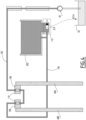
FIG. 4 is a schematic view of a control system according to a second embodiment of the invention; -
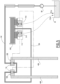
FIG. 5 is a schematic view of a control system according to a third embodiment of the invention, and -
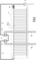
FIG. 6 is a schematic view of a control system according to a fourth embodiment of the invention. - Aspects set forth below represent the necessary information to enable those skilled in the art to practice the disclosure.
- A
vehicle 10 according to the invention is represented onfigure 1 . Thevehicle 10 is a road vehicle, here a truck. Alternatively, thevehicle 10 is a bus, or a different type of heavy duty vehicle. Thevehicle 10 comprises anengine 12, to generate motion power,wheels 14, and atransmission 16 to transmit the motion power to the wheels. Following the traction power from theengine 16 to thewheels 14, thetransmission 16 includes aclutch 18, agearbox 20, a transmission shaft 22, atransfer case 24, and from thetransfer case 24, afront drive shaft 26A leading to afront differential 28A, and arear drive shaft 26B leading to arear differential 28B. Thegearbox 20 is controlled by a driver of thevehicle 10, here with agearstick 30. - A non-limitative example of the
gearbox 20 is schematically shown onfigure 2 . Thegearbox 20 is represented in a working orientation, which corresponds to an orientation of thegearbox 20 when mounted on thevehicle 10 that rests on a horizontal surface. Thegearbox 20 comprises adrive shaft 32, which is configured to be driven by theengine 12 through theclutch 18, arange shaft 34, which is configured to be connected to the transmission shaft 22. Therange shaft 34 is aligned with thedrive shaft 32. Thegearbox 20 also comprises amain shaft 36, which is arranged between, and aligned with, thedrive shaft 32 and therange shaft 34. In the illustrated example, therange 34 comprises aplanetary gear set 38A, which is arranged around a fixedcentral gear 36A arranged at an end of themain shaft 36. Thegear box 20 also comprises acounter shaft 40, which extends parallel to themain shaft 36. - Each shaft among the
drive shaft 32, therange shaft 34, themain shaft 36 comprises one ormore gears wheels 42, each gear wheel being associated with arespective counter gear 44 of thecountershaft 40. Thegear wheels 42 and the planetary gear set 38A are selectively locked in rotation or freed in rotation relative to the respective shaft on which they are mounted, by means of a set of slidingsleeves 46. The position of eachsleeve 46 is controlled by arespective fork 48. In the illustrated example, thegearbox 20 comprises foursleeves 46, each associated with arespective fork 48. Thegearbox 20 also comprises acontrol unit 50, also called "GCU" in short for gearbox control unit, which controls the position of eachfork 48. - The
gearbox 20 also comprises acasing 50, which delimits anoil sump 52. Theoil sump 52 is an internal volume of thecasing 50, configured to be filled with lubrication oil for various elements of the gearbox, in particular for thecountershaft 40. - Depending on the position of each
sleeve 46, each guided by arespective fork 48, a specific ratio between a rotation speed of thedrive shaft 32 and a rotation speed of therange shaft 24 is achieved. In a specific configuration of thegearbox 20 called "direct drive", the driving force of thedrive shaft 32 is transmitted to themain shaft 36 without passing through thecountershaft 40. As a result, the counter gears 44 do not require as much cooling and lubrication as in other configurations of thegearbox 20. It is therefore possible to reduce the oil level in theoil sump 52, in order to reduce churning losses. It is however still necessary to lubricate and cool themain shaft 36. To this end, thegearbox 20 usually comprises anoil supply system 54, for example an oil pump, which is configured to pump oil from theoil sump 52 and pour the oil onto thegear wheels 42 and/or onto bearings supporting the main shaft 63 when thevehicle 10 is in use. The bearings are not represented. Theoil supply 54 is pressurized when thevehicle 10 is in use. - The
forks 48 include afirst fork 48A called "split fork", which operates one of thesleeves 46 arranged between thedrive shaft 32 and thecountershaft 40, and asecond fork 48B called "2/3 fork", which operates one of thesleeves 46 arranged between thecountershaft 40 and themain shaft 36. The direct drive configuration is associated with a specific position of the first andsecond forks -
Figure 3 is a schematic representation of a control system 100 for controlling an oil level in thegearbox 20. Together, thegearbox 20 and the control system 100 are part of a gearbox assembly. The control system 100 comprises asupply line 102, which is configured to be connected to a pressurized upstream oil supply of thegearbox 20. For example, thesupply line 102 is connected to theoil pump 54. When thevehicle 10 operates normally, in particular when thegearbox 20 is in the direct drive configuration, thesupply line 102 is filled with pressurized oil. For example, thesupply line 102 is a hose, or a metallic pipe. - The control system 100 also comprises a
return line 104, which is configured to be connected to thesupply line 102, afirst valve 106 and asecond valve 108. Thefirst valve 106 is configured to be controlled by thefirst fork 48A of thegearbox 20, and to switch between an open position and a closed position, according to a position of thefirst fork 48A. Thesecond valve 108 is configured to be controlled by thesecond fork 48B of thegearbox 20, and to switch between an open position and a closed position, according to a position of thesecond fork 48B. - The
supply line 102 and thereturn line 104 are connected to each other through thefirst valve 106 and thesecond valve 108, the first andsecond valves second valves second forks gearbox 20, so that thereturn line 104 is pressurized when bothvalves supply line 102 is pressurized. - Preferably, the
first valve 106 and thesecond valve 108 are both piston valves, that let pass the oil pressure when in the open position. Eachvalve piston 110, that is guided inside a cylinder and whose position is controlled by therespective fork - The control system 100 also comprises a
flow control unit 112, which is connected to thereturn line 104 and which is configured to lower the oil level in thegearbox 20 when thereturn line 104 is pressurized. More precisely, theflow control unit 112 is configured to lower the oil level in theoil sump 52 when thereturn line 104 is pressurized, i.e. when thegearbox 20 is in the direct drive configuration, causing the first andsecond valves pump 54 functions properly. If one of the components of the control system 100 among thepump 54, thesupply line 102, thefirst valve 106, thesecond valve 108 and thereturn line 104, does not work properly, then the pressure in thereturn line 104 drops, leading to theflow control unit 112 to stop lowering the oil level in theoil sump 52. In other words, theflow control unit 112 lowers the oil level in theoil sump 52 as long as thefirst valve 106 and thesecond valve 108 are both in the open configuration. As soon as at least one of the first and second valves is in the closed configuration, theflow control unit 112 stops lowering the oil level in theoil sump 52. The setup of the control system 100 has the advantageous feature that it will reset if the oil system pressure is lost, for instance if thevehicle 10 stops or if the oil level in theoils sump 52 is to low and thepump 54 starts sucking air. - In the first embodiment of the invention, the
flow control unit 112 comprises athird valve 114, which is different from the first andsecond valves third valve 114 is a spring-loaded piston actuator that controls the oil level in theoil sump 52. - A control system 200 according to an alternative second embodiment of the invention is represented on
Figure 4 . In this embodiment, the parts of the control system 200 identical or similar to the ones of the first embodiment have the same reference numerals. Hereafter, mainly the differences between the first and second embodiments are detailed. - In this second embodiment, the control system 200 comprises an
oil reservoir 202, which is connected to thereturn line 104 and which is filled by oil flowing through thesupply line 102 and thereturn line 104 when the first andsecond valves gearbox 20 is in the direct drive configuration, both thefirst valve 106 and thesecond valve 108 are in the open configuration. Thesupply line 102 and thereturn line 104 are pressurized by thepump 54, and the oil from theoil sump 52 is pumped by thepump 54 into thereservoir 202. - The
flow control unit 112 comprises adump valve 214, which is in a closed configuration when thereturn line 104 is pressurized, and in an open configuration otherwise. Thedump valve 214 is arranged between thereservoir 202 and theoil sump 52 of thegearbox 20, so that oil contained in thereservoir 202 flows into the oil sump when thedump valve 214 is in the open position, that is to say when at least one of the first andsecond valves figure 4 , the flow of oil from thedump valve 214 to theoil sump 52 is represented by an arrow F214 in broken line. In other words, thereservoir 202 is a buffer reservoir for the oil of theoil sump 52. When thegearbox 20 is in the direct drive gear selection, the oil from theoil sump 52 is transferred to thereservoir 202. When thegearbox 20 quits the direct drive gear selection, the oil flows back from thereservoir 202 to theoil sump 52. Depending on the spatial arrangement of thedump valve 214 relatively to theoil sump 52, a return duct is arranged between thedump valve 214 and theoil sump 52. The return duct is not represented. Preferably, the oil from thereservoir 202 flows tooil sump 52 by gravity, i.e. without any specific pump, so that the control system 200 remains robust. - A control system 300 according to an alternative third embodiment of the invention is represented on
Figure 5 . In this embodiment, the parts of the control system 300 identical or similar to the ones of the previous embodiments have the same reference numerals. Here-after, mainly the differences between the first and second embodiments are detailed. - In this third embodiment, the control system 300 comprises a
reservoir 302, which is integrated in thecontrol unit 50. Theflow control unit 112 comprises twodump valves 314, eachdump valve 314 being controlled by a respective valve among thefirst valve 106 and thesecond valve 108. When thefirst valve 106 is in the open configuration, then the associateddump valve 314 is in the closed configuration, whereas when thefirst valve 106 is in the closed configuration, then the associateddump valve 314 is in the open configuration. Similarly, when thesecond valve 108 is in the open configuration, then the associateddump valve 314 is in the closed configuration, whereas when thesecond valve 108 is in the closed configuration, then the associateddump valve 314 is in the open configuration. In other words, oil contained in thereservoir 302 flows into theoil sump 52 when at least one of thefirst valve 106 and thesecond valve 108 is the closed position. Onfigure 5 , the flow of oil from eachdump valve 314 to theoil sump 52 is represented by a respective arrow F314 in broken line. In an alternative, not shown embodiment, at least one valve among thefirst valve 106 and thesecond valve 108 is integrated with the associateddump valve 314. For example, thefirst valve 106 and the associateddump valve 314 share thesame piston 110. - A control system 400 according to an alternative fourth embodiment of the invention is represented on
Figure 6 . In this embodiment, the parts of the control system 400 identical or similar to the ones of the previous embodiments have the same reference numerals. Here-after, mainly the differences between the first and second embodiments are detailed. - In this fourth embodiment, the control system 400, the
flow control unit 112 comprises a two-splitoil gutter 414. Theoil gutter 414 comprises afixed part 416, here with parallel slits, and amobile part 418, which is mobile between a closed position, where themobile part 418 prevents the oil to flow through thefixed part 416, and an open position, where themobile part 418 does not prevent the oil to flow through thefixed part 416. When thereturn line 104 is pressurized, themobile part 418 is pushed to the closed position, whereas when thereturn line 104 is not pressurized, themobile part 418 moves back to its open position thanks to areturn element 420, here represented by a spring. Onfigure 6 , theoil gutter 414 is shown in a closed configuration. - The terminology used herein is for the purpose of describing particular aspects only and is not intended to be limiting of the disclosure. As used herein, the singular forms "a", "an", and "the" are intended to include the plural forms as well, unless the context clearly indicates otherwise. As used herein, the term "and/or" includes any and all combinations of one or more of the associated listed items. It will be further understood that the terms "comprises", "comprising", "includes", and/or "including" when used herein specify the presence of stated features, integers, steps, operations, elements, and/or components, but do not preclude the presence or addition of one or more other features, integers, steps, operations, elements, components, and/or groups thereof.
- It will be understood that, although the terms first, second, etc., may be used herein to describe various elements, these elements should not be limited by these terms. These terms are only used to distinguish one element from another. For example, a first element could be termed a second element, and, similarly, a second element could be termed a first element without departing from the scope of the present disclosure.
- Relative terms such as "below" or "above" or "upper" or "lower" or "horizontal" or "vertical" may be used herein to describe a relationship of one element to another element as illustrated in the Figures. It will be understood that these terms and those discussed above are intended to encompass different orientations of the device in addition to the orientation depicted in the Figures. It will be understood that when an element is referred to as being "connected" or "coupled" to another element, it can be directly connected or coupled to the other element, or intervening elements may be present. In contrast, when an element is referred to as being "directly connected" or "directly coupled" to another element, there are no intervening elements present.
- Unless otherwise defined, all terms (including technical and scientific terms) used herein have the same meaning as commonly understood by one of ordinary skill in the art to which this disclosure belongs. It will be further understood that terms used herein should be interpreted as having a meaning consistent with their meaning in the context of this specification and the relevant art and will not be interpreted in an idealized or overly formal sense unless expressly so defined herein.
- It is to be understood that the present disclosure is not limited to the aspects described above and illustrated in the drawings; rather, the skilled person will recognize that many changes and modifications may be made within the scope of the present disclosure and appended claims. In the drawings and specification, there have been disclosed aspects for purposes of illustration only and not for purposes of limitation, the scope of the inventive concepts being set forth in the following claims.
Claims (8)
- A control system (100 ; 200 ; 300 ; 400) for controlling an oil level in a gearbox (20) of a vehicle (10), the control system (100 ; 200 ; 300 ; 400) comprising:- a supply line (102), which is configured to be connected to a pressurized upstream oil supply (54) of the gearbox (20),- a return line (104), which is configured to be connected to the supply line (102),- a first valve (106) and a second valve (108),wherein:- the first valve (106) is configured:• to be controlled by a first fork (48A) of the gearbox (20), and• to switch between an open position and a closed position, according to a position of the first fork (48A),- the second valve (108) is configured:• to be controlled by a second fork (48B) of the gearbox (20), the second fork being different from the first fork (48A), and• to switch between an open position and a closed position, according to a position of the second fork (48B),- a first end of the return line (104) is connected to the supply line (102) through the first valve (106) and the second valve (108), the first and second valves being arranged in serial, the first and second valves being both in the open position when the first and second forks are together in a direct drive configuration that engages a direct drive gear selection of the gearbox (20), so that the return line (104) is pressurized when both valves are open and when the supply line (102) is pressurized,- the control system (100 ; 200 ; 300 ; 400) comprises a flow control unit (112), which is connected to a second end of the return line (104) and which is configured to lower the oil level in an oil sump (52) of the gearbox (20) when the return line (104) is pressurized.
- The control system (100 ; 200 ; 300 ; 400) according to claim 1, wherein :- the first valve (106) and the second valve (108) are both piston valves.
- The control system (100 ; 200 ; 300 ; 400) according to any one of claims 1 or 2, wherein:- the flow control unit (112) comprises a third valve (114), which is different from the first valve (106) and from the second valve (108) and which is a closed position when the return line (104) is pressurized,- the third valve (114) is configured to prevent oil from a filling circuit to fill the oil sump (52) when the third valve (114) is in the closed position.
- The control system (200 ; 300) according to any one of claims 1 to 3, wherein:- the control system comprises an oil reservoir (202 ; 302), which is connected to the return line (104) and which is filled by oil flowing through the supply line (102) and the return line (104) when the first and second valves (106, 108) are both in an open position,- the flow control unit (112) comprises a dump valve (214 ; 314), which is arranged between the reservoir (202 ; 302) and the oil sump (52), so that oil contained in the reservoir (202 ; 302) flows into the oil sump when at least one of the first valve (106) and the second valve (108) is the closed position.
- The control system (300) according to claim 4, wherein:- the oil reservoir (302) is part of a gearbox control unit (50) of the gearbox (20).
- The control system (400) according to anyone of claims 1 to 3, wherein :- the flow control unit (112) comprises a two-split oil gutter (414), with a fixed part (416) and a mobile part (418), the mobile part being in a closed position when the return line (104) is pressurized.
- A gearbox assembly, comprising:- a gearbox (20), and- the control system (100 ; 200 ; 300 ; 400) according to any one of claims 1 to 6, wherein- the gearbox (20) comprises a main shaft (36) and a countershaft (40), a gear ratio of the gearbox being controlled by several forks (48), including a first fork (48A) and a second fork (48B), the gearbox (20) having a direct drive configuration, where traction power does not pass through the countershaft and where the first fork (48A) and the second fork (48B) are in the direct drive configuration that engages the direct drive gear selection of the gearbox (20).
- A vehicle (10), comprising a gearbox assembly according to claim 7.
Priority Applications (3)
| Application Number | Priority Date | Filing Date | Title |
|---|---|---|---|
| EP22209683.6A EP4375542B1 (en) | 2022-11-25 | 2022-11-25 | Control system for controlling an oil level in a gearbox of a vehicle, associated gearbox assembly and vehicle |
| US18/513,728 US12449031B2 (en) | 2022-11-25 | 2023-11-20 | Control system for controlling an oil level in a gearbox of a vehicle, associated gearbox assembly and vehicle |
| CN202311567786.0A CN118088660A (en) | 2022-11-25 | 2023-11-22 | Control system for controlling the oil level of a vehicle transmission, related transmission assembly and vehicle |
Applications Claiming Priority (1)
| Application Number | Priority Date | Filing Date | Title |
|---|---|---|---|
| EP22209683.6A EP4375542B1 (en) | 2022-11-25 | 2022-11-25 | Control system for controlling an oil level in a gearbox of a vehicle, associated gearbox assembly and vehicle |
Publications (2)
| Publication Number | Publication Date |
|---|---|
| EP4375542A1 true EP4375542A1 (en) | 2024-05-29 |
| EP4375542B1 EP4375542B1 (en) | 2025-11-26 |
Family
ID=84362904
Family Applications (1)
| Application Number | Title | Priority Date | Filing Date |
|---|---|---|---|
| EP22209683.6A Active EP4375542B1 (en) | 2022-11-25 | 2022-11-25 | Control system for controlling an oil level in a gearbox of a vehicle, associated gearbox assembly and vehicle |
Country Status (3)
| Country | Link |
|---|---|
| US (1) | US12449031B2 (en) |
| EP (1) | EP4375542B1 (en) |
| CN (1) | CN118088660A (en) |
Citations (3)
| Publication number | Priority date | Publication date | Assignee | Title |
|---|---|---|---|---|
| US6644439B2 (en) * | 2000-10-17 | 2003-11-11 | Daimlerchrysler Ag | Transmission for an internal combustion engine |
| WO2008076061A1 (en) * | 2006-12-18 | 2008-06-26 | Scania Cv Ab | A method to reduce the rotary resistance at gear wheels of a gear box at a motor vehicle, and a gear box to carry out the method |
| EP3227584B1 (en) * | 2014-12-04 | 2019-08-14 | Scania CV AB | Lubrication system and a method for controlling the lubrication system |
Family Cites Families (4)
| Publication number | Priority date | Publication date | Assignee | Title |
|---|---|---|---|---|
| JP2005106266A (en) | 2003-09-11 | 2005-04-21 | Honda Motor Co Ltd | Vehicle drive device |
| AT517704B1 (en) | 2015-08-19 | 2017-04-15 | Avl Commercial Driveline & Tractor Eng Gmbh | Method for controlling the oil level in a transmission and transmission for carrying out the method |
| CN106195234B (en) * | 2016-09-29 | 2024-05-17 | 长沙悠力传动有限公司 | Gear box system with adjustable oil level height |
| CN114673781B (en) * | 2022-04-15 | 2025-03-25 | 东风商用车有限公司 | A lubrication structure and gearbox for controlling gearbox oil level height to improve transmission efficiency |
-
2022
- 2022-11-25 EP EP22209683.6A patent/EP4375542B1/en active Active
-
2023
- 2023-11-20 US US18/513,728 patent/US12449031B2/en active Active
- 2023-11-22 CN CN202311567786.0A patent/CN118088660A/en active Pending
Patent Citations (3)
| Publication number | Priority date | Publication date | Assignee | Title |
|---|---|---|---|---|
| US6644439B2 (en) * | 2000-10-17 | 2003-11-11 | Daimlerchrysler Ag | Transmission for an internal combustion engine |
| WO2008076061A1 (en) * | 2006-12-18 | 2008-06-26 | Scania Cv Ab | A method to reduce the rotary resistance at gear wheels of a gear box at a motor vehicle, and a gear box to carry out the method |
| EP3227584B1 (en) * | 2014-12-04 | 2019-08-14 | Scania CV AB | Lubrication system and a method for controlling the lubrication system |
Also Published As
| Publication number | Publication date |
|---|---|
| EP4375542B1 (en) | 2025-11-26 |
| US20240175487A1 (en) | 2024-05-30 |
| US12449031B2 (en) | 2025-10-21 |
| CN118088660A (en) | 2024-05-28 |
Similar Documents
| Publication | Publication Date | Title |
|---|---|---|
| JP5868522B2 (en) | Drive system and electric vehicle equipped with the drive system | |
| US9683561B2 (en) | Drive train cooling arrangement and method for operating same | |
| AU742759B2 (en) | Mechanical transmission cooling and lubricating using associated engine systems | |
| KR101283950B1 (en) | Transmission hydraulic control system having a pump bypass valve | |
| CN101535688B (en) | Hydraulic controls for dual clutch transmissions | |
| US10780853B2 (en) | External lube system for a transmission | |
| RU2628264C2 (en) | Mechanism of power selection, vehicle with such mechanism and intermediary item for such mechanism | |
| EP2610517B1 (en) | Hydraulic system, driving system and electric vehicle | |
| US10436084B2 (en) | Utility vehicle fluid cooling | |
| CN103038549B (en) | There is the speed changer of main-gear box and power output unit | |
| CN113124151A (en) | Special gearbox hydraulic system for hybrid power capable of smoothly shifting gears | |
| SE541602C2 (en) | A lubrication system for a gearbox arranged in a vehicle | |
| CN204164295U (en) | Floating type hydraulic transmission gearbox | |
| EP4375542B1 (en) | Control system for controlling an oil level in a gearbox of a vehicle, associated gearbox assembly and vehicle | |
| US8322252B2 (en) | Step-change transmission having charge and variable displacement pumps | |
| KR101137163B1 (en) | Hydraulic drive for mobile vehicles | |
| US7299891B2 (en) | Hydraulic drive mechanism for mobile vehicles | |
| CN103591280A (en) | Transmission clutch piston compensator feed circuit | |
| US7703352B2 (en) | Hydrostatic-mechanical transmission | |
| CN215172159U (en) | Special gearbox hydraulic system for hybrid power capable of smoothly shifting gears | |
| JP2001074130A (en) | Hydraulic mechanism of vehicle transmission | |
| CN202441831U (en) | Power shifting gearbox of engineering mechanical vehicle | |
| EP3869059A1 (en) | Assembly for activating a clutch in the drivetrain of a motor vehicle | |
| EP1657416A1 (en) | Cooling system for farming tractors | |
| KR20160071519A (en) | Transmission for heavy construction equipment with lubrication oil cooling struture |
Legal Events
| Date | Code | Title | Description |
|---|---|---|---|
| PUAI | Public reference made under article 153(3) epc to a published international application that has entered the european phase |
Free format text: ORIGINAL CODE: 0009012 |
|
| STAA | Information on the status of an ep patent application or granted ep patent |
Free format text: STATUS: THE APPLICATION HAS BEEN PUBLISHED |
|
| AK | Designated contracting states |
Kind code of ref document: A1 Designated state(s): AL AT BE BG CH CY CZ DE DK EE ES FI FR GB GR HR HU IE IS IT LI LT LU LV MC ME MK MT NL NO PL PT RO RS SE SI SK SM TR |
|
| STAA | Information on the status of an ep patent application or granted ep patent |
Free format text: STATUS: REQUEST FOR EXAMINATION WAS MADE |
|
| 17P | Request for examination filed |
Effective date: 20241105 |
|
| RBV | Designated contracting states (corrected) |
Designated state(s): AL AT BE BG CH CY CZ DE DK EE ES FI FR GB GR HR HU IE IS IT LI LT LU LV MC ME MK MT NL NO PL PT RO RS SE SI SK SM TR |
|
| STAA | Information on the status of an ep patent application or granted ep patent |
Free format text: STATUS: EXAMINATION IS IN PROGRESS |
|
| 17Q | First examination report despatched |
Effective date: 20250514 |
|
| GRAP | Despatch of communication of intention to grant a patent |
Free format text: ORIGINAL CODE: EPIDOSNIGR1 |
|
| RIC1 | Information provided on ipc code assigned before grant |
Ipc: F16H 57/04 20100101AFI20250702BHEP Ipc: F16H 3/091 20060101ALN20250702BHEP Ipc: F16H 37/04 20060101ALN20250702BHEP Ipc: F16H 63/00 20060101ALN20250702BHEP |
|
| STAA | Information on the status of an ep patent application or granted ep patent |
Free format text: STATUS: GRANT OF PATENT IS INTENDED |
|
| INTG | Intention to grant announced |
Effective date: 20250807 |
|
| GRAS | Grant fee paid |
Free format text: ORIGINAL CODE: EPIDOSNIGR3 |
|
| GRAA | (expected) grant |
Free format text: ORIGINAL CODE: 0009210 |
|
| STAA | Information on the status of an ep patent application or granted ep patent |
Free format text: STATUS: THE PATENT HAS BEEN GRANTED |
|
| AK | Designated contracting states |
Kind code of ref document: B1 Designated state(s): AL AT BE BG CH CY CZ DE DK EE ES FI FR GB GR HR HU IE IS IT LI LT LU LV MC ME MK MT NL NO PL PT RO RS SE SI SK SM TR |
|
| REG | Reference to a national code |
Ref country code: CH Ref legal event code: F10 Free format text: ST27 STATUS EVENT CODE: U-0-0-F10-F00 (AS PROVIDED BY THE NATIONAL OFFICE) Effective date: 20251126 Ref country code: GB Ref legal event code: FG4D |
|
| REG | Reference to a national code |
Ref country code: DE Ref legal event code: R096 Ref document number: 602022025570 Country of ref document: DE |
|
| REG | Reference to a national code |
Ref country code: IE Ref legal event code: FG4D |
|
| REG | Reference to a national code |
Ref country code: NL Ref legal event code: MP Effective date: 20251126 |
|
| PG25 | Lapsed in a contracting state [announced via postgrant information from national office to epo] |
Ref country code: ES Free format text: LAPSE BECAUSE OF FAILURE TO SUBMIT A TRANSLATION OF THE DESCRIPTION OR TO PAY THE FEE WITHIN THE PRESCRIBED TIME-LIMIT Effective date: 20251126 |
|
| REG | Reference to a national code |
Ref country code: LT Ref legal event code: MG9D |
|
| PG25 | Lapsed in a contracting state [announced via postgrant information from national office to epo] |
Ref country code: NO Free format text: LAPSE BECAUSE OF FAILURE TO SUBMIT A TRANSLATION OF THE DESCRIPTION OR TO PAY THE FEE WITHIN THE PRESCRIBED TIME-LIMIT Effective date: 20260226 |
|
| PG25 | Lapsed in a contracting state [announced via postgrant information from national office to epo] |
Ref country code: HR Free format text: LAPSE BECAUSE OF FAILURE TO SUBMIT A TRANSLATION OF THE DESCRIPTION OR TO PAY THE FEE WITHIN THE PRESCRIBED TIME-LIMIT Effective date: 20251126 Ref country code: FI Free format text: LAPSE BECAUSE OF FAILURE TO SUBMIT A TRANSLATION OF THE DESCRIPTION OR TO PAY THE FEE WITHIN THE PRESCRIBED TIME-LIMIT Effective date: 20251126 Ref country code: AT Free format text: LAPSE BECAUSE OF FAILURE TO SUBMIT A TRANSLATION OF THE DESCRIPTION OR TO PAY THE FEE WITHIN THE PRESCRIBED TIME-LIMIT Effective date: 20251126 |
|
| REG | Reference to a national code |
Ref country code: AT Ref legal event code: MK05 Ref document number: 1861335 Country of ref document: AT Kind code of ref document: T Effective date: 20251126 |
|
| PG25 | Lapsed in a contracting state [announced via postgrant information from national office to epo] |
Ref country code: NL Free format text: LAPSE BECAUSE OF FAILURE TO SUBMIT A TRANSLATION OF THE DESCRIPTION OR TO PAY THE FEE WITHIN THE PRESCRIBED TIME-LIMIT Effective date: 20251126 |
|
| PG25 | Lapsed in a contracting state [announced via postgrant information from national office to epo] |
Ref country code: RS Free format text: LAPSE BECAUSE OF FAILURE TO SUBMIT A TRANSLATION OF THE DESCRIPTION OR TO PAY THE FEE WITHIN THE PRESCRIBED TIME-LIMIT Effective date: 20260226 |
|
| PG25 | Lapsed in a contracting state [announced via postgrant information from national office to epo] |
Ref country code: IS Free format text: LAPSE BECAUSE OF FAILURE TO SUBMIT A TRANSLATION OF THE DESCRIPTION OR TO PAY THE FEE WITHIN THE PRESCRIBED TIME-LIMIT Effective date: 20260326 |
|
| PG25 | Lapsed in a contracting state [announced via postgrant information from national office to epo] |
Ref country code: PT Free format text: LAPSE BECAUSE OF FAILURE TO SUBMIT A TRANSLATION OF THE DESCRIPTION OR TO PAY THE FEE WITHIN THE PRESCRIBED TIME-LIMIT Effective date: 20260326 |
|
| PG25 | Lapsed in a contracting state [announced via postgrant information from national office to epo] |
Ref country code: PL Free format text: LAPSE BECAUSE OF FAILURE TO SUBMIT A TRANSLATION OF THE DESCRIPTION OR TO PAY THE FEE WITHIN THE PRESCRIBED TIME-LIMIT Effective date: 20251126 |
|
| PG25 | Lapsed in a contracting state [announced via postgrant information from national office to epo] |
Ref country code: LV Free format text: LAPSE BECAUSE OF FAILURE TO SUBMIT A TRANSLATION OF THE DESCRIPTION OR TO PAY THE FEE WITHIN THE PRESCRIBED TIME-LIMIT Effective date: 20251126 |
|
| PG25 | Lapsed in a contracting state [announced via postgrant information from national office to epo] |
Ref country code: BG Free format text: LAPSE BECAUSE OF FAILURE TO SUBMIT A TRANSLATION OF THE DESCRIPTION OR TO PAY THE FEE WITHIN THE PRESCRIBED TIME-LIMIT Effective date: 20251126 |