EP4375499A1 - Fluid turbine with parachute-like catchers - Google Patents
Fluid turbine with parachute-like catchers Download PDFInfo
- Publication number
- EP4375499A1 EP4375499A1 EP21950375.2A EP21950375A EP4375499A1 EP 4375499 A1 EP4375499 A1 EP 4375499A1 EP 21950375 A EP21950375 A EP 21950375A EP 4375499 A1 EP4375499 A1 EP 4375499A1
- Authority
- EP
- European Patent Office
- Prior art keywords
- rotor
- catchers
- opening
- catcher
- fluid turbine
- Prior art date
- Legal status (The legal status is an assumption and is not a legal conclusion. Google has not performed a legal analysis and makes no representation as to the accuracy of the status listed.)
- Granted
Links
Images
Classifications
-
- F—MECHANICAL ENGINEERING; LIGHTING; HEATING; WEAPONS; BLASTING
- F03—MACHINES OR ENGINES FOR LIQUIDS; WIND, SPRING, OR WEIGHT MOTORS; PRODUCING MECHANICAL POWER OR A REACTIVE PROPULSIVE THRUST, NOT OTHERWISE PROVIDED FOR
- F03B—MACHINES OR ENGINES FOR LIQUIDS
- F03B3/00—Machines or engines of reaction type; Parts or details peculiar thereto
- F03B3/04—Machines or engines of reaction type; Parts or details peculiar thereto with substantially axial flow throughout rotors, e.g. propeller turbines
-
- F—MECHANICAL ENGINEERING; LIGHTING; HEATING; WEAPONS; BLASTING
- F03—MACHINES OR ENGINES FOR LIQUIDS; WIND, SPRING, OR WEIGHT MOTORS; PRODUCING MECHANICAL POWER OR A REACTIVE PROPULSIVE THRUST, NOT OTHERWISE PROVIDED FOR
- F03B—MACHINES OR ENGINES FOR LIQUIDS
- F03B17/00—Other machines or engines
- F03B17/06—Other machines or engines using liquid flow with predominantly kinetic energy conversion, e.g. of swinging-flap type, "run-of-river", "ultra-low head"
- F03B17/062—Other machines or engines using liquid flow with predominantly kinetic energy conversion, e.g. of swinging-flap type, "run-of-river", "ultra-low head" with rotation axis substantially at right angle to flow direction
- F03B17/065—Other machines or engines using liquid flow with predominantly kinetic energy conversion, e.g. of swinging-flap type, "run-of-river", "ultra-low head" with rotation axis substantially at right angle to flow direction the flow engaging parts having a cyclic movement relative to the rotor during its rotation
-
- F—MECHANICAL ENGINEERING; LIGHTING; HEATING; WEAPONS; BLASTING
- F03—MACHINES OR ENGINES FOR LIQUIDS; WIND, SPRING, OR WEIGHT MOTORS; PRODUCING MECHANICAL POWER OR A REACTIVE PROPULSIVE THRUST, NOT OTHERWISE PROVIDED FOR
- F03B—MACHINES OR ENGINES FOR LIQUIDS
- F03B17/00—Other machines or engines
- F03B17/06—Other machines or engines using liquid flow with predominantly kinetic energy conversion, e.g. of swinging-flap type, "run-of-river", "ultra-low head"
- F03B17/062—Other machines or engines using liquid flow with predominantly kinetic energy conversion, e.g. of swinging-flap type, "run-of-river", "ultra-low head" with rotation axis substantially at right angle to flow direction
-
- F—MECHANICAL ENGINEERING; LIGHTING; HEATING; WEAPONS; BLASTING
- F03—MACHINES OR ENGINES FOR LIQUIDS; WIND, SPRING, OR WEIGHT MOTORS; PRODUCING MECHANICAL POWER OR A REACTIVE PROPULSIVE THRUST, NOT OTHERWISE PROVIDED FOR
- F03B—MACHINES OR ENGINES FOR LIQUIDS
- F03B3/00—Machines or engines of reaction type; Parts or details peculiar thereto
- F03B3/12—Blades; Blade-carrying rotors
-
- F—MECHANICAL ENGINEERING; LIGHTING; HEATING; WEAPONS; BLASTING
- F03—MACHINES OR ENGINES FOR LIQUIDS; WIND, SPRING, OR WEIGHT MOTORS; PRODUCING MECHANICAL POWER OR A REACTIVE PROPULSIVE THRUST, NOT OTHERWISE PROVIDED FOR
- F03D—WIND MOTORS
- F03D3/00—Wind motors with rotation axis substantially perpendicular to the air flow entering the rotor
-
- F—MECHANICAL ENGINEERING; LIGHTING; HEATING; WEAPONS; BLASTING
- F03—MACHINES OR ENGINES FOR LIQUIDS; WIND, SPRING, OR WEIGHT MOTORS; PRODUCING MECHANICAL POWER OR A REACTIVE PROPULSIVE THRUST, NOT OTHERWISE PROVIDED FOR
- F03D—WIND MOTORS
- F03D3/00—Wind motors with rotation axis substantially perpendicular to the air flow entering the rotor
- F03D3/005—Wind motors with rotation axis substantially perpendicular to the air flow entering the rotor the axis being vertical
-
- F—MECHANICAL ENGINEERING; LIGHTING; HEATING; WEAPONS; BLASTING
- F03—MACHINES OR ENGINES FOR LIQUIDS; WIND, SPRING, OR WEIGHT MOTORS; PRODUCING MECHANICAL POWER OR A REACTIVE PROPULSIVE THRUST, NOT OTHERWISE PROVIDED FOR
- F03D—WIND MOTORS
- F03D3/00—Wind motors with rotation axis substantially perpendicular to the air flow entering the rotor
- F03D3/005—Wind motors with rotation axis substantially perpendicular to the air flow entering the rotor the axis being vertical
- F03D3/009—Wind motors with rotation axis substantially perpendicular to the air flow entering the rotor the axis being vertical of the drag type, e.g. Savonius
-
- F—MECHANICAL ENGINEERING; LIGHTING; HEATING; WEAPONS; BLASTING
- F03—MACHINES OR ENGINES FOR LIQUIDS; WIND, SPRING, OR WEIGHT MOTORS; PRODUCING MECHANICAL POWER OR A REACTIVE PROPULSIVE THRUST, NOT OTHERWISE PROVIDED FOR
- F03D—WIND MOTORS
- F03D3/00—Wind motors with rotation axis substantially perpendicular to the air flow entering the rotor
- F03D3/06—Rotors
-
- F—MECHANICAL ENGINEERING; LIGHTING; HEATING; WEAPONS; BLASTING
- F03—MACHINES OR ENGINES FOR LIQUIDS; WIND, SPRING, OR WEIGHT MOTORS; PRODUCING MECHANICAL POWER OR A REACTIVE PROPULSIVE THRUST, NOT OTHERWISE PROVIDED FOR
- F03D—WIND MOTORS
- F03D3/00—Wind motors with rotation axis substantially perpendicular to the air flow entering the rotor
- F03D3/06—Rotors
- F03D3/062—Rotors characterised by their construction elements
-
- F—MECHANICAL ENGINEERING; LIGHTING; HEATING; WEAPONS; BLASTING
- F05—INDEXING SCHEMES RELATING TO ENGINES OR PUMPS IN VARIOUS SUBCLASSES OF CLASSES F01-F04
- F05B—INDEXING SCHEME RELATING TO WIND, SPRING, WEIGHT, INERTIA OR LIKE MOTORS, TO MACHINES OR ENGINES FOR LIQUIDS COVERED BY SUBCLASSES F03B, F03D AND F03G
- F05B2210/00—Working fluid
- F05B2210/16—Air or water being indistinctly used as working fluid, i.e. the machine can work equally with air or water without any modification
-
- F—MECHANICAL ENGINEERING; LIGHTING; HEATING; WEAPONS; BLASTING
- F05—INDEXING SCHEMES RELATING TO ENGINES OR PUMPS IN VARIOUS SUBCLASSES OF CLASSES F01-F04
- F05B—INDEXING SCHEME RELATING TO WIND, SPRING, WEIGHT, INERTIA OR LIKE MOTORS, TO MACHINES OR ENGINES FOR LIQUIDS COVERED BY SUBCLASSES F03B, F03D AND F03G
- F05B2220/00—Application
- F05B2220/30—Application in turbines
-
- F—MECHANICAL ENGINEERING; LIGHTING; HEATING; WEAPONS; BLASTING
- F05—INDEXING SCHEMES RELATING TO ENGINES OR PUMPS IN VARIOUS SUBCLASSES OF CLASSES F01-F04
- F05B—INDEXING SCHEME RELATING TO WIND, SPRING, WEIGHT, INERTIA OR LIKE MOTORS, TO MACHINES OR ENGINES FOR LIQUIDS COVERED BY SUBCLASSES F03B, F03D AND F03G
- F05B2240/00—Components
- F05B2240/20—Rotors
- F05B2240/24—Rotors for turbines
- F05B2240/242—Rotors for turbines of reaction type
-
- F—MECHANICAL ENGINEERING; LIGHTING; HEATING; WEAPONS; BLASTING
- F05—INDEXING SCHEMES RELATING TO ENGINES OR PUMPS IN VARIOUS SUBCLASSES OF CLASSES F01-F04
- F05B—INDEXING SCHEME RELATING TO WIND, SPRING, WEIGHT, INERTIA OR LIKE MOTORS, TO MACHINES OR ENGINES FOR LIQUIDS COVERED BY SUBCLASSES F03B, F03D AND F03G
- F05B2240/00—Components
- F05B2240/20—Rotors
- F05B2240/30—Characteristics of rotor blades, i.e. of any element transforming dynamic fluid energy to or from rotational energy and being attached to a rotor
- F05B2240/31—Characteristics of rotor blades, i.e. of any element transforming dynamic fluid energy to or from rotational energy and being attached to a rotor of changeable form or shape
- F05B2240/311—Characteristics of rotor blades, i.e. of any element transforming dynamic fluid energy to or from rotational energy and being attached to a rotor of changeable form or shape flexible or elastic
-
- F—MECHANICAL ENGINEERING; LIGHTING; HEATING; WEAPONS; BLASTING
- F05—INDEXING SCHEMES RELATING TO ENGINES OR PUMPS IN VARIOUS SUBCLASSES OF CLASSES F01-F04
- F05B—INDEXING SCHEME RELATING TO WIND, SPRING, WEIGHT, INERTIA OR LIKE MOTORS, TO MACHINES OR ENGINES FOR LIQUIDS COVERED BY SUBCLASSES F03B, F03D AND F03G
- F05B2280/00—Materials; Properties thereof
- F05B2280/40—Organic materials
- F05B2280/4006—Polyamides, e.g. NYLON
-
- F—MECHANICAL ENGINEERING; LIGHTING; HEATING; WEAPONS; BLASTING
- F05—INDEXING SCHEMES RELATING TO ENGINES OR PUMPS IN VARIOUS SUBCLASSES OF CLASSES F01-F04
- F05D—INDEXING SCHEME FOR ASPECTS RELATING TO NON-POSITIVE-DISPLACEMENT MACHINES OR ENGINES, GAS-TURBINES OR JET-PROPULSION PLANTS
- F05D2240/00—Components
- F05D2240/20—Rotors
- F05D2240/30—Characteristics of rotor blades, i.e. of any element transforming dynamic fluid energy to or from rotational energy and being attached to a rotor
-
- F—MECHANICAL ENGINEERING; LIGHTING; HEATING; WEAPONS; BLASTING
- F05—INDEXING SCHEMES RELATING TO ENGINES OR PUMPS IN VARIOUS SUBCLASSES OF CLASSES F01-F04
- F05D—INDEXING SCHEME FOR ASPECTS RELATING TO NON-POSITIVE-DISPLACEMENT MACHINES OR ENGINES, GAS-TURBINES OR JET-PROPULSION PLANTS
- F05D2250/00—Geometry
- F05D2250/30—Arrangement of components
- F05D2250/33—Arrangement of components symmetrical
-
- F—MECHANICAL ENGINEERING; LIGHTING; HEATING; WEAPONS; BLASTING
- F05—INDEXING SCHEMES RELATING TO ENGINES OR PUMPS IN VARIOUS SUBCLASSES OF CLASSES F01-F04
- F05D—INDEXING SCHEME FOR ASPECTS RELATING TO NON-POSITIVE-DISPLACEMENT MACHINES OR ENGINES, GAS-TURBINES OR JET-PROPULSION PLANTS
- F05D2300/00—Materials; Properties thereof
- F05D2300/40—Organic materials
- F05D2300/43—Synthetic polymers, e.g. plastics; Rubber
- F05D2300/433—Polyamides, e.g. NYLON
-
- Y—GENERAL TAGGING OF NEW TECHNOLOGICAL DEVELOPMENTS; GENERAL TAGGING OF CROSS-SECTIONAL TECHNOLOGIES SPANNING OVER SEVERAL SECTIONS OF THE IPC; TECHNICAL SUBJECTS COVERED BY FORMER USPC CROSS-REFERENCE ART COLLECTIONS [XRACs] AND DIGESTS
- Y02—TECHNOLOGIES OR APPLICATIONS FOR MITIGATION OR ADAPTATION AGAINST CLIMATE CHANGE
- Y02E—REDUCTION OF GREENHOUSE GAS [GHG] EMISSIONS, RELATED TO ENERGY GENERATION, TRANSMISSION OR DISTRIBUTION
- Y02E10/00—Energy generation through renewable energy sources
- Y02E10/70—Wind energy
- Y02E10/74—Wind turbines with rotation axis perpendicular to the wind direction
Definitions
- the fluid turbine with parachute catchers can be used to produce energy from air or water currents.
- the task of the present invention is to provide a turbine with a simple, light and compact construction that allows reset of the tested pressure against the direction of rotation.
- the turbine consists of the following elements:
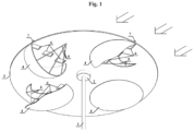
- Figure 1 shows a three-dimensional bottom view of a turbine with four catchers, located on one level.
- FIG. 1 shows one variant of the turbine according to the present invention.
- the device consists of a vertical axis (1) that passes through two bearing rings (2), and on which a rotor (3) is located in the form of a flat horizontal disk.
- Four catchers (4) are suspended below the rotor (3), each of them being made of ripstop nylon in the form of a half-chamber, open on one side.
- the above edge of the opening of each half-chamber is immovably fixed to the rotor (3), and the side edges are clamped to one end of three flexible links (5) whose second end is attached to the rotor (3).
- All catchers (4) are positioned so that their openings are oriented in the same direction of rotation relative to the axis (1), namely clockwise direction.
- each catcher (4) On the upper side of the rotor (3), above the opening of each catcher (4), there are three valves (6) with air intakes (7) directed under an angle of 75 degrees to the radius of the rotor passing through them.
- the valves (6) lead to the interior of the catchers (4).
- the wind enters the turbine from any direction (the direction it is indicated by arrows in the figure), thereby exerting pressure on all catchers (4).
- the rotor (3) is viewed as a clock face and the wind comes from the "6 o'clock” direction
- the one of the catchers (4) located closest to the "9 o'clock” position captures the pressure in the interior of its half-chamber, causing it to expand and tightens its links (5), from where the pressure is transmitted to the rotor (3) and rotates it around axis (1).
- the wind pressure on all other catchers (4) is lateral or opposite to their openings, and causes them vertically folding to a flat horizontal position - a shape with zero aerodynamic resistance.
- each catcher (4) successively falls to the "9 o'clock” position and dissolves under the pressure of side of its opening and under the influence of its weight, then in the "12 o'clock” position shrinks under lateral pressure to a flat shape and remains in that position until moving to the "6 o'clock” position.
- the wind instantly gets direct access to the interior of the catcher (4), and causes its full dissolution, giving an additional rotary motion to the rotor (3), during the entire transition between the "6 o'clock" and "12 o'clock” positions.
- the air intakes (7) stop supplying air to the corresponding catcher (4) before stopping the wind pressure through the opening of the same catcher (4), and remain in this state until approaching the "6 o'clock” position.
- the rotor (3) exerts constant aerodynamic drag, balanced relative to axis (1), whose value is negligibly small. The process continues until the wind stops.
- the device can be applied to capture the mechanical pressure and extract the energy from fluid flows. Because its catchers are made of flexible and light material, it is characterized by a simple structure, light weight, and easy production and repair. Also, the device has a large working area, and reduces to a negligibly small value the aerodynamic resistance in the reversible half revolution of the rotor, which further increases its efficiency.
Landscapes
- Engineering & Computer Science (AREA)
- Chemical & Material Sciences (AREA)
- Combustion & Propulsion (AREA)
- Mechanical Engineering (AREA)
- General Engineering & Computer Science (AREA)
- Life Sciences & Earth Sciences (AREA)
- Sustainable Development (AREA)
- Sustainable Energy (AREA)
- Power Engineering (AREA)
- Wind Motors (AREA)
Abstract
Description
- The fluid turbine with parachute catchers can be used to produce energy from air or water currents.
- No existing analogues of the proposed device are known. Some vertical axis wind turbines are known that capture the wind with sails, such as that shown in the patent
GB 2451089 US 10385824 - The task of the present invention is to provide a turbine with a simple, light and compact construction that allows reset of the tested pressure against the direction of rotation.
- The turbine consists of the following elements:
- a vertical axis, located in one or several bearing rings, and a rotor in the form of a flat horizontal disk, fixed to the upper end of the axis;
- one or more diametrical pairs of catchers are suspended below the rotor, such as the catchers of each pair are centrally symmetrical to each other relative to the axis;
- each catcher is made of flexible material and in the passive position has a half-chamber shape that has an opening on one side; the opening of each catcher has a top edge and a side edge;
- the upper edge of the opening of each half-chamber is immovably fixed to the rotor, and the side edge of the opening of each half-chamber is clamped to the rotor by two or more flexible links, the first end of each flexible link being attached to the side edge of the catcher opening, and the second end of each flexible link is attached to the rotor;
- the openings of all catchers are oriented in the same direction of rotation relative to the axis - either clockwise or counterclockwise;
- on the upper side of the rotor, above the opening of each catcher, are located one or more valves with air intakes directed at an angle greater than 45 degrees, relative to the radius of the rotor passing through them;
- the valves are in their open position and are directed to the interior of the catchers;
- in one embodiment, the catchers are located on one level;
- in another embodiment, the rotor has a configuration with two or more levels, as in this configuration, the catchers are located one above the other, on two or more levels;
- in another embodiment, each rotor level has an odd number of catchers;
- in another embodiment, the catchers are made of ripstop nylon or polyester.
-
Figure 1 shows a three-dimensional bottom view of a turbine with four catchers, located on one level. -
Figure 1 shows one variant of the turbine according to the present invention. The device consists of a vertical axis (1) that passes through two bearing rings (2), and on which a rotor (3) is located in the form of a flat horizontal disk. Four catchers (4) are suspended below the rotor (3), each of them being made of ripstop nylon in the form of a half-chamber, open on one side. The above edge of the opening of each half-chamber is immovably fixed to the rotor (3), and the side edges are clamped to one end of three flexible links (5) whose second end is attached to the rotor (3). All catchers (4) are positioned so that their openings are oriented in the same direction of rotation relative to the axis (1), namely clockwise direction. On the upper side of the rotor (3), above the opening of each catcher (4), there are three valves (6) with air intakes (7) directed under an angle of 75 degrees to the radius of the rotor passing through them. The valves (6) lead to the interior of the catchers (4). - During its operation, the wind enters the turbine from any direction (the direction it is indicated by arrows in the figure), thereby exerting pressure on all catchers (4). If the rotor (3) is viewed as a clock face and the wind comes from the "6 o'clock" direction, the one of the catchers (4) located closest to the "9 o'clock" position, captures the pressure in the interior of its half-chamber, causing it to expand and tightens its links (5), from where the pressure is transmitted to the rotor (3) and rotates it around axis (1). At the same time, the wind pressure on all other catchers (4) is lateral or opposite to their openings, and causes them vertically folding to a flat horizontal position - a shape with zero aerodynamic resistance. This vertical folding takes place relative to the areas of attaching the upper edges of the respective catchers (4) to the rotor (3), which are pivot points. In the induced rotation process of the rotor (3), each catcher (4) successively falls to the "9 o'clock" position and dissolves under the pressure of side of its opening and under the influence of its weight, then in the "12 o'clock" position shrinks under lateral pressure to a flat shape and remains in that position until moving to the "6 o'clock" position. At the same time, under the influence of the affected pressure of the wind, in the "12 o'clock" position, the catcher (4) is moved to the periphery of the rotor (3), in position "3 o'clock" turns to leeward and covers its links (5), and in "6 o'clock" position is moved to axis (1). Also, when approaching position "6 o'clock" the air intakes (7) begin to capture the wind before the corresponding catcher (4), still compressed, and feed it through their valves (6), thus accelerating the initial expansion of the catcher opening (4), and begin to inflate it immediately after moving to the "6 o'clock" position. Then the wind instantly gets direct access to the interior of the catcher (4), and causes its full dissolution, giving an additional rotary motion to the rotor (3), during the entire transition between the "6 o'clock" and "12 o'clock" positions. When approaching a position "12 o'clock" due to its position, the air intakes (7) stop supplying air to the corresponding catcher (4) before stopping the wind pressure through the opening of the same catcher (4), and remain in this state until approaching the "6 o'clock" position. Through all the time the rotor (3) exerts constant aerodynamic drag, balanced relative to axis (1), whose value is negligibly small. The process continues until the wind stops.
- The device can be applied to capture the mechanical pressure and extract the energy from fluid flows. Because its catchers are made of flexible and light material, it is characterized by a simple structure, light weight, and easy production and repair. Also, the device has a large working area, and reduces to a negligibly small value the aerodynamic resistance in the reversible half revolution of the rotor, which further increases its efficiency.
-
- 1
- Vertical axis
- 2
- Bearing rings
- 3
- Rotor
- 4
- Catchers
- 5
- Flexible connections
- 6
- Valves
- 7
- Air intakes
Claims (5)
- A fluid turbine consisting of a vertical axis, a rotor and parachute catchers, characterized in that it consists of the following elements:- a vertical axis 1, located in one or several bearing rings 2, and a rotor 3 in the form of a flat horizontal disk, fixed to the upper end of the axis 1;- one or more diametrical pairs of catchers 4 are suspended below the rotor 3, such as the catchers 4 of each pair are centrally symmetrical to each other relative to the axis 1;- each catcher 4 is made of flexible material and in the passive position has a half-chamber shape that has an opening on one side; the opening of each catcher 4 has a top edge and a side edge;- the upper edge of the opening of each half-chamber is immovably fixed to the rotor 3, and the side edge of the opening of each half-chamber is clamped to the rotor 3 by two or more flexible links 5, the first end of each flexible link 5 being attached to the side edge of the catcher 4 opening, and the second end of each flexible link 5 is attached to the rotor 3;- the openings of all catchers 4 are oriented in the same direction of rotation relative to the axis 1 - either clockwise or counterclockwise;- on the upper side of the rotor 3, above the opening of each catcher 4, are located one or more valves 6 with air intakes 7 directed at an angle greater than 45 degrees, relative to the radius of the rotor 3 passing through them;- the valves 6 are in their open position and are directed to the interior of the catchers 4.
- Fluid turbine according to claim 1,
characterized in that
the catchers 4 are located on one level. - Fluid turbine according to claim 1,
characterized in that
the rotor 3 has a configuration with two or more levels, as in this configuration, the catchers 4 are located one above the other, on two or more levels. - Fluid turbine according to claims 1-3
characterized in that
each rotor 3 level has an odd number of catchers 4. - Fluid turbine according to claims 1-4,
characterized in that
the catchers 4 are made of ripstop nylon or polyester.
Applications Claiming Priority (1)
| Application Number | Priority Date | Filing Date | Title |
|---|---|---|---|
| PCT/BG2021/000021 WO2023000043A1 (en) | 2021-07-19 | 2021-07-19 | Fluid turbine with parachute-like catchers |
Publications (4)
| Publication Number | Publication Date |
|---|---|
| EP4375499A1 true EP4375499A1 (en) | 2024-05-29 |
| EP4375499A4 EP4375499A4 (en) | 2025-04-23 |
| EP4375499B1 EP4375499B1 (en) | 2025-11-26 |
| EP4375499C0 EP4375499C0 (en) | 2025-11-26 |
Family
ID=84980443
Family Applications (1)
| Application Number | Title | Priority Date | Filing Date |
|---|---|---|---|
| EP21950375.2A Active EP4375499B1 (en) | 2021-07-19 | 2021-07-19 | Fluid turbine with parachute-like catchers |
Country Status (3)
| Country | Link |
|---|---|
| US (1) | US12129823B2 (en) |
| EP (1) | EP4375499B1 (en) |
| WO (1) | WO2023000043A1 (en) |
Family Cites Families (15)
| Publication number | Priority date | Publication date | Assignee | Title |
|---|---|---|---|---|
| GB2071773A (en) | 1979-11-30 | 1981-09-23 | Liu Thung Chi | Wind Propelled Device |
| US4545729A (en) * | 1983-07-28 | 1985-10-08 | Joe Storm | Wind turbine apparatus |
| SU1409772A1 (en) | 1986-12-15 | 1988-07-15 | Д.П.Квач | Windmill |
| ITTN20060006A1 (en) * | 2006-04-20 | 2007-10-21 | Gianfranco Oradini | VERTICAL AXIS ROTATIONAL SYSTEM AND SAIL CONCEPTION FOR WIND ENERGY PRODUCTION |
| EP1887220A3 (en) * | 2006-07-25 | 2013-09-11 | Jakob Hasler | Wind turbine unit with vertical rotation axis |
| GB2451089A (en) | 2007-07-16 | 2009-01-21 | Robert Stephen Palmer | Wind turbine with folding sails |
| US8210817B2 (en) * | 2010-04-13 | 2012-07-03 | Seven International Group, Inc. | Wind turbine utilizing wind directing slats |
| NL2004627C2 (en) * | 2010-04-29 | 2011-11-01 | West 6 B V | TURBINE. |
| RU2453727C1 (en) * | 2011-01-26 | 2012-06-20 | Александр Владимирович Губанов | Horizontal turbine wind-powered generator |
| US20130115086A1 (en) | 2011-11-04 | 2013-05-09 | Steven C. Hench | Vertical axis wind turbine |
| EP3232050B1 (en) * | 2014-04-03 | 2021-03-17 | WindTree GmbH | A fluid turbine with rotor |
| US9752557B2 (en) * | 2015-01-30 | 2017-09-05 | John Nicklas | Vertical axis turbine |
| JP6241467B2 (en) * | 2015-09-11 | 2017-12-06 | カシオ計算機株式会社 | Imaging apparatus, imaging control apparatus, imaging method, imaging control method, and program |
| US10385824B2 (en) | 2016-10-18 | 2019-08-20 | Bruce Logan Shrewsbury | Wind turbine |
| US11143164B1 (en) * | 2018-04-26 | 2021-10-12 | Epic Metals Corporation | Vertical windmill blade |
-
2021
- 2021-07-19 EP EP21950375.2A patent/EP4375499B1/en active Active
- 2021-07-19 WO PCT/BG2021/000021 patent/WO2023000043A1/en not_active Ceased
- 2021-07-19 US US18/549,216 patent/US12129823B2/en active Active
Also Published As
| Publication number | Publication date |
|---|---|
| EP4375499B1 (en) | 2025-11-26 |
| US12129823B2 (en) | 2024-10-29 |
| WO2023000043A1 (en) | 2023-01-26 |
| EP4375499A4 (en) | 2025-04-23 |
| EP4375499C0 (en) | 2025-11-26 |
| US20240151203A1 (en) | 2024-05-09 |
Similar Documents
| Publication | Publication Date | Title |
|---|---|---|
| US4247253A (en) | Vertical axis wind turbine | |
| US4288200A (en) | Wind tower turbine | |
| US8899937B2 (en) | Excessive wind portal for wind turbines | |
| US3938907A (en) | Horizontal multidirectional turbine windmill | |
| US4180367A (en) | Self-starting windmill energy conversion system | |
| US6749394B2 (en) | Rotating display apparatus | |
| US20090001730A1 (en) | Vertical axis windmill with wingletted air-tiltable blades | |
| WO2004015266A1 (en) | Turbine apparatus and method | |
| RU2392490C1 (en) | Carousel-type wind-electric set (wes) with cyclic symmetric blades smoothly rotating in opposite phase to rotor | |
| WO2015166477A1 (en) | A vertical axis wind turbine with self-orientating blades | |
| TW201819758A (en) | Vertical axis wind turbine with automatic adjustment of blade angle | |
| US8128363B2 (en) | Wind flap brake assembly for wind turbine | |
| US4571152A (en) | Vertical axis windmill | |
| US5131805A (en) | Dual axis fluid current motor | |
| US5784978A (en) | Wind energy catchment device | |
| US20060078416A1 (en) | Vertical axis wind or water turbine | |
| WO2010139600A1 (en) | Wind concentrator for a vertical axis wind turbine | |
| US12129823B2 (en) | Fluid turbine with parachute-like catchers | |
| US4098034A (en) | Building sway control | |
| GB2051252A (en) | Apparatus for Extracting Energy from a Fluid Current | |
| EP1808599A2 (en) | Vertical axis fluid actuated turbine | |
| US11326577B2 (en) | Wind and water turbine apparatuses | |
| US11965481B2 (en) | Wind power system | |
| ITVR20000045A1 (en) | HIGH AERODYNAMIC YIELD MILL. | |
| GB2071773A (en) | Wind Propelled Device |
Legal Events
| Date | Code | Title | Description |
|---|---|---|---|
| STAA | Information on the status of an ep patent application or granted ep patent |
Free format text: STATUS: THE INTERNATIONAL PUBLICATION HAS BEEN MADE |
|
| PUAI | Public reference made under article 153(3) epc to a published international application that has entered the european phase |
Free format text: ORIGINAL CODE: 0009012 |
|
| STAA | Information on the status of an ep patent application or granted ep patent |
Free format text: STATUS: REQUEST FOR EXAMINATION WAS MADE |
|
| 17P | Request for examination filed |
Effective date: 20240326 |
|
| AK | Designated contracting states |
Kind code of ref document: A1 Designated state(s): AL AT BE BG CH CY CZ DE DK EE ES FI FR GB GR HR HU IE IS IT LI LT LU LV MC MK MT NL NO PL PT RO RS SE SI SK SM TR |
|
| DAV | Request for validation of the european patent (deleted) | ||
| DAX | Request for extension of the european patent (deleted) | ||
| REG | Reference to a national code |
Ref country code: DE Free format text: PREVIOUS MAIN CLASS: F03B0017060000 Ref country code: DE Ref legal event code: R079 Ref document number: 602021043403 Country of ref document: DE Free format text: PREVIOUS MAIN CLASS: F03B0017060000 Ipc: F03D0003060000 |
|
| A4 | Supplementary search report drawn up and despatched |
Effective date: 20250320 |
|
| RIC1 | Information provided on ipc code assigned before grant |
Ipc: F03B 17/06 20060101ALI20250314BHEP Ipc: F03D 3/00 20060101ALI20250314BHEP Ipc: F03D 3/06 20060101AFI20250314BHEP |
|
| GRAP | Despatch of communication of intention to grant a patent |
Free format text: ORIGINAL CODE: EPIDOSNIGR1 |
|
| STAA | Information on the status of an ep patent application or granted ep patent |
Free format text: STATUS: GRANT OF PATENT IS INTENDED |
|
| GRAS | Grant fee paid |
Free format text: ORIGINAL CODE: EPIDOSNIGR3 |
|
| INTG | Intention to grant announced |
Effective date: 20250922 |
|
| GRAA | (expected) grant |
Free format text: ORIGINAL CODE: 0009210 |
|
| STAA | Information on the status of an ep patent application or granted ep patent |
Free format text: STATUS: THE PATENT HAS BEEN GRANTED |
|
| AK | Designated contracting states |
Kind code of ref document: B1 Designated state(s): AL AT BE BG CH CY CZ DE DK EE ES FI FR GB GR HR HU IE IS IT LI LT LU LV MC MK MT NL NO PL PT RO RS SE SI SK SM TR |
|
| REG | Reference to a national code |
Ref country code: CH Ref legal event code: F10 Free format text: ST27 STATUS EVENT CODE: U-0-0-F10-F00 (AS PROVIDED BY THE NATIONAL OFFICE) Effective date: 20251126 Ref country code: GB Ref legal event code: FG4D |
|
| REG | Reference to a national code |
Ref country code: IE Ref legal event code: FG4D |
|
| U01 | Request for unitary effect filed |
Effective date: 20251208 |
|
| U07 | Unitary effect registered |
Designated state(s): AT BE BG DE DK EE FI FR IT LT LU LV MT NL PT RO SE SI Effective date: 20251211 |
|
| PG25 | Lapsed in a contracting state [announced via postgrant information from national office to epo] |
Ref country code: ES Free format text: LAPSE BECAUSE OF FAILURE TO SUBMIT A TRANSLATION OF THE DESCRIPTION OR TO PAY THE FEE WITHIN THE PRESCRIBED TIME-LIMIT Effective date: 20251126 |
|
| PG25 | Lapsed in a contracting state [announced via postgrant information from national office to epo] |
Ref country code: NO Free format text: LAPSE BECAUSE OF FAILURE TO SUBMIT A TRANSLATION OF THE DESCRIPTION OR TO PAY THE FEE WITHIN THE PRESCRIBED TIME-LIMIT Effective date: 20260226 |
|
| PG25 | Lapsed in a contracting state [announced via postgrant information from national office to epo] |
Ref country code: HR Free format text: LAPSE BECAUSE OF FAILURE TO SUBMIT A TRANSLATION OF THE DESCRIPTION OR TO PAY THE FEE WITHIN THE PRESCRIBED TIME-LIMIT Effective date: 20251126 |
|
| PG25 | Lapsed in a contracting state [announced via postgrant information from national office to epo] |
Ref country code: RS Free format text: LAPSE BECAUSE OF FAILURE TO SUBMIT A TRANSLATION OF THE DESCRIPTION OR TO PAY THE FEE WITHIN THE PRESCRIBED TIME-LIMIT Effective date: 20260226 |
|
| PG25 | Lapsed in a contracting state [announced via postgrant information from national office to epo] |
Ref country code: IS Free format text: LAPSE BECAUSE OF FAILURE TO SUBMIT A TRANSLATION OF THE DESCRIPTION OR TO PAY THE FEE WITHIN THE PRESCRIBED TIME-LIMIT Effective date: 20260326 |
|
| PG25 | Lapsed in a contracting state [announced via postgrant information from national office to epo] |
Ref country code: PL Free format text: LAPSE BECAUSE OF FAILURE TO SUBMIT A TRANSLATION OF THE DESCRIPTION OR TO PAY THE FEE WITHIN THE PRESCRIBED TIME-LIMIT Effective date: 20251126 |
|
| PG25 | Lapsed in a contracting state [announced via postgrant information from national office to epo] |
Ref country code: SM Free format text: LAPSE BECAUSE OF FAILURE TO SUBMIT A TRANSLATION OF THE DESCRIPTION OR TO PAY THE FEE WITHIN THE PRESCRIBED TIME-LIMIT Effective date: 20251126 |
|
| PG25 | Lapsed in a contracting state [announced via postgrant information from national office to epo] |
Ref country code: CZ Free format text: LAPSE BECAUSE OF FAILURE TO SUBMIT A TRANSLATION OF THE DESCRIPTION OR TO PAY THE FEE WITHIN THE PRESCRIBED TIME-LIMIT Effective date: 20251126 |
|
| PG25 | Lapsed in a contracting state [announced via postgrant information from national office to epo] |
Ref country code: SK Free format text: LAPSE BECAUSE OF FAILURE TO SUBMIT A TRANSLATION OF THE DESCRIPTION OR TO PAY THE FEE WITHIN THE PRESCRIBED TIME-LIMIT Effective date: 20251126 |