EP4375478A2 - Abrufbare antiextrusionsrückfaltringsicherung für dichtungselement - Google Patents
Abrufbare antiextrusionsrückfaltringsicherung für dichtungselement Download PDFInfo
- Publication number
- EP4375478A2 EP4375478A2 EP24169083.3A EP24169083A EP4375478A2 EP 4375478 A2 EP4375478 A2 EP 4375478A2 EP 24169083 A EP24169083 A EP 24169083A EP 4375478 A2 EP4375478 A2 EP 4375478A2
- Authority
- EP
- European Patent Office
- Prior art keywords
- backup
- extrusion
- abutment
- extrusion backup
- well barrier
- Prior art date
- Legal status (The legal status is an assumption and is not a legal conclusion. Google has not performed a legal analysis and makes no representation as to the accuracy of the status listed.)
- Granted
Links
Images





Classifications
-
- E—FIXED CONSTRUCTIONS
- E21—EARTH OR ROCK DRILLING; MINING
- E21B—EARTH OR ROCK DRILLING; OBTAINING OIL, GAS, WATER, SOLUBLE OR MELTABLE MATERIALS OR A SLURRY OF MINERALS FROM WELLS
- E21B33/00—Sealing or packing boreholes or wells
- E21B33/10—Sealing or packing boreholes or wells in the borehole
- E21B33/12—Packers; Plugs
- E21B33/1208—Packers; Plugs characterised by the construction of the sealing or packing means
- E21B33/1216—Anti-extrusion means, e.g. means to prevent cold flow of rubber packing
-
- E—FIXED CONSTRUCTIONS
- E21—EARTH OR ROCK DRILLING; MINING
- E21B—EARTH OR ROCK DRILLING; OBTAINING OIL, GAS, WATER, SOLUBLE OR MELTABLE MATERIALS OR A SLURRY OF MINERALS FROM WELLS
- E21B23/00—Apparatus for displacing, setting, locking, releasing or removing tools, packers or the like in boreholes or wells
- E21B23/06—Apparatus for displacing, setting, locking, releasing or removing tools, packers or the like in boreholes or wells for setting packers
-
- E—FIXED CONSTRUCTIONS
- E21—EARTH OR ROCK DRILLING; MINING
- E21B—EARTH OR ROCK DRILLING; OBTAINING OIL, GAS, WATER, SOLUBLE OR MELTABLE MATERIALS OR A SLURRY OF MINERALS FROM WELLS
- E21B33/00—Sealing or packing boreholes or wells
- E21B33/10—Sealing or packing boreholes or wells in the borehole
- E21B33/12—Packers; Plugs
- E21B33/128—Packers; Plugs with a member expanded radially by axial pressure
Definitions
- This disclosure relates generally to equipment utilized and operations performed in conjunction with a subterranean well and, in one example described below, more particularly provides for retrieving a well barrier having an anti-extrusion backup for a seal element.
- the well tool It is sometimes desirable to be able to retrieve a well tool from a well. In such circumstances, it is desirable for the well tool to have an outer size that is smaller than any obstructions or restrictions through which the well tool must pass while it is being retrieved.
- Some well tools such as well barriers (packers, plugs, hangers, etc.) are expanded in operation in a well. If the well tool has been expanded downhole, it can be difficult to retrieve the tool through the obstructions or restrictions.
- an anti-extrusion backup system that expands when set and collapses or retracts when unset.
- This anti-extrusion backup system is very easy to retrieve from mono-bore wells and through wellbore restrictions.
- This anti-extrusion backup system is suitable for high pressure and high temperature well barriers (such as, bridge plugs, packers, liner hangers, etc.).
- the anti-extrusion backup system addresses the problem of extrusion in some examples by using overlapping foldback rings that are slotted or perforated in anti-extrusion backups.
- the foldback rings are seated against a sliding sleeve that is pre-energized in its initial position, with enough force to reposition the foldback rings to their initial position after use.
- the foldback rings When the barrier is set downhole, the foldback rings are deformed to act as a backup to the sealing elements, and the foldback rings are supported by the sliding sleeve and a fixed gage connector.
- the sleeve slides over the connector and compresses a spring stack, so that the sliding sleeve is fully-energized in its set position.
- gage connector and sliding sleeve provide enough support for the foldback rings during operation.
- the energized sleeve slides over the fixed gage connector and shifts the foldback rings to a retracted retrieve position, typically below gage (but in some cases could be slightly above gage or at gage).
- the sliding sleeve can slide over the foldback rings when they are below gage, or shift the foldback rings to a retrieve position. Note that the sliding sleeve can also be pushed or pulled in position by various different means (i.e., not necessarily a spring stack).
- FIG. 1 depicts examples of the anti-extrusion backup system used on a well barrier in set and unset configurations.
- Certain drawings depict an example in run-in (or run in hole "RIH"), set, equalized and unset configurations.
- the foldback rings are extended radially outward when the seal elements are compressed to set the barrier, and the foldback rings are retracted inward by the sliding sleeve when the barrier is unset.
- FIG. 1 Representatively illustrated in FIG. 1 is a system 10 for use with a subterranean well, and an associated method, which can embody principles of this disclosure.
- system 10 and method are merely one example of an application of the principles of this disclosure in practice, and a wide variety of other examples are possible. Therefore, the scope of this disclosure is not limited at all to the details of the system 10 and method described herein and/or depicted in the drawings.
- a wellbore 12 is lined with casing 14 and cement 16.
- the wellbore 12 is generally vertical and extends into an earth formation 18.
- the wellbore 12 may be uncased or open hole in locations in which the principles of this disclosure are practiced.
- the wellbore 12 could be generally horizontal or otherwise inclined from vertical.
- the scope of this disclosure is not limited to any of the details of the components of the system 10 or the well with which they are used.
- a well barrier 20 is connected as part of a tubular string 22 positioned in the wellbore 12.
- the well barrier 20 is used to prevent flow through all or a portion of the wellbore 12, for example, in order to isolate sections of the wellbore from each other.
- the well barrier 20 depicted in FIG. 1 is of the type known to those skilled in the art as a tubing retrievable packer, but other types of well barriers (such as, bridge plugs, frac plugs, liner hangers, etc.) may be used in other examples.
- the well barrier 20 it is not necessary for the well barrier 20 to be conveyed into or retrieved from the wellbore 12 using the tubular string 22 (for example, the well barrier could instead be conveyed and/or retrieved using wireline, slick line, coiled tubing or other type of conveyance).
- the scope of this disclosure is not limited to use of any particular type of well barrier, any particular type of conveyance, or to any particular details of the well barrier 20 as described herein or depicted in the drawings.
- the well barrier 20 is configured to seal off an annulus 24 formed radially between the tubular string 22 and the wellbore 12.
- the well barrier 20 includes a radially outwardly extendable seal section 26.
- the seal section 26 includes a seal element that can extend radially outward into sealing contact with an inner wall of the casing 14. If the wellbore 12 is uncased, the seal element can sealingly engage a wall of the earth formation 18.
- the well barrier 20 in this example also includes an anchor or slip section 28.
- the slip section 28 secures the well barrier 20 against displacement relative to the wellbore 12.
- the slip section 28 can enable the well barrier 20 to support loads applied to the well barrier from above or below, and the slip section can resist displacement due to a pressure differential applied across the seal section 26.
- a flow passage 30 extends longitudinally through the well barrier 20 and tubular string 22.
- the flow passage 30 may not extend through the well barrier 20 (for example, if the well barrier is a bridge plug, etc.).
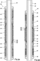
- FIGS. 2A & B cross-sectional views of an example of the seal section 26 is representatively illustrated, apart from the system 10 and a remainder of the well barrier 20. Note that the seal section examples 26 described herein and depicted in the drawings may be used with other well barriers and in other systems, in keeping with the principles of this disclosure.
- the seal section 26 depicted in FIG. 2 is configured to be positioned on an inner mandrel 32 of the well barrier 20 (not shown in FIGS. 2A & B , see FIG. 4 ).
- the seal section 26 includes multiple annular seal elements 34 positioned longitudinally between two gage connectors or abutments 36.
- the seal elements 34 are configured so that they will extend radially outward when the seal elements are longitudinally compressed between the abutments 36.
- the abutments 36 are connected to respective upper and lower connectors 38.
- the connectors 38 control the positions of the abutments 36, for example, enabling a distance between the abutments to be decreased (to thereby longitudinally compress the seal elements 34 between the abutments), and enabling the distance between the abutments to be increased (to thereby radially inwardly retract the seal elements).
- the abutments 36 and connectors 38 may not be separate components, but could instead be integrally formed.
- the scope of this disclosure is not limited to use of any particular components, combination of components, or arrangement or configuration of components in the seal section 26.
- the seal section 26 depicted in FIGS. 2A & B also includes anti-extrusion backups 40.
- the anti-extrusion backups 40 operate to completely or partially fill a radial gap (e.g., the annulus 24 in the FIG. 1 system 10) between the well barrier 26 and the surface against which the seal elements 34 seal. This helps to prevent or minimize any extrusion of the seal elements 34 through the gap due to a pressure differential across the seal elements.
- the seal section 26 is in an unset configuration.
- the seal elements 34 are not radially extended.
- the seal section 26 is in a set configuration.
- the longitudinal distance between the abutments 36 is decreased (as compared to FIG. 2A ), and the seal elements 34 are thereby longitudinally compressed and radial outwardly extended.
- anti-extrusion backups 40 are also radially outwardly extended in the FIG. 2B set configuration.
- the anti-extrusion backups 40 preferably, but not necessarily, contact the surface against which the seal elements 34 seal in the set configuration.
- the seal section 26 can be essentially returned to its FIG. 2A configuration. In this manner, the well barrier 20 can be retrieved through any restrictions, obstructions, etc., through which it previously passed prior to being set.
- the longitudinal distance between the abutments 36 is increased. This allows the seal elements 34 to elongate and radially inwardly retract out of engagement with the surface against which it previously sealed.
- the anti-extrusion backups 40 are radially inwardly retracted in this example by use of a biasing device 42 and sleeve 44 to apply a biasing force against a radially outward portion of each backup. This causes the backup 40 to rotate toward the adjacent seal element 34 as it radially retracts, so that the backup retracts along with the seal element.
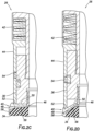
- FIG. 2C a more detailed cross-sectional view of this example of the backup 40, the biasing device 42 and the sleeve 44 is representatively illustrated in the set configuration.
- the abutment 36 is displaced downward toward the seal element 34 when the well barrier 20 is set. This compresses the backup 40 between the abutment 36 and the seal element 34, causing an intermediate portion of the backup to rotate so that it extends radially outward.
- a radially inward portion 46 of the backup 40 is secured to the abutment 36, so that the radially inward portion displaces (or remains motionless) with the abutment.
- a radially outward portion 48 of the backup 40 is able to displace longitudinally somewhat relative to the radially inward portion 46 and the abutment 36.
- the backup 40 can rotate between the radially inward and radially outward portions 46, 48.
- the anti-extrusion backup 40 includes an annular-shaped fold-back ring 50.
- the fold-back ring 50 facilitates return of the anti-extrusion backup 40 to its radially retracted unset configuration (see FIG. 2D ).
- the fold-back ring 50 can be stiffer than the intermediate portion of the anti-extrusion backup 40 between the radially inward and radially outward portions 46, 48, so that the fold-back ring helps the anti-extrusion backup to maintain its shape as it transitions from the set to the unset configuration.
- the sleeve 44 radially outwardly surrounds the abutment 36 and is positioned to apply a biasing force to the radially outward portion 48 of the backup 40.
- the fold-back ring 50 is configured with a shoulder 52 for secure engagement with an end of the sleeve 44 in both of the set and unset configurations.
- the biasing force exerted by the biasing device 42 via the sleeve 44 to the anti-extrusion backup 40 has caused the backup to rotate to its retracted unset configuration.
- the anti-extrusion backup 50 and the seal element 34 have an outer diameter that is no greater than that of a gage diameter of the well barrier 20 (such as, a maximum outer diameter of the sleeve 44) in the unset configuration.
- the sleeve 44 contacts the anti-extrusion backup 40 in both the set and unset configurations.
- the biasing device 42 may be pre-loaded, so that a biasing force is exerted against the radially outward portion 48 of the backup 40 in the unset configuration.
- the biasing force may be increased as the sleeve 44 displaces relative to the abutment 36 to the set configuration. This increased biasing force may then be used to rotate the backup 40 back to its retracted unset configuration when it is desired to retrieve the well barrier 20.
- the biasing device 42 in this example comprises a stack of Belleville spring washers.
- the biasing device 42 could comprise another type of spring, an elastomer, a piston and pressurized chamber, or any other device capable of applying a resilient biasing force to the anti-extrusion backup 40.
- a shear screw 54 releasably secures against relative displacement between the abutment 36 and the sleeve 44.
- the shear screw is sheared, thereby permitting relative displacement between the abutment 36 and the sleeve 44.
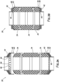
- FIGS. 3A & B another example of the seal section 26 is representatively illustrated in respective unset and set configurations.
- the sleeve 44 is not used. Instead, the biasing device 42 applies the biasing force directly to the anti-extrusion backup 40.
- the fold-back ring 50 is not used in the anti-extrusion backup 40 of FIGS. 3A & B .
- FIG. 3A it may be seen that the intermediate portion of the backup 40 is provided with perforations or slots 54 to make it more readily deformable.
- the backup 40 could comprise overlapping radially extending flexible leaves, or another arrangement suitable for deforming from the unset to the set configuration, and then deforming from the set to the unset configuration.
- the biasing device 42 in the FIGS. 3A & B example comprises multiple Belleville spring washers stacked in a same orientation. In this manner, one of the spring washers is in contact with the intermediate portion of the anti-extrusion backup 40.
- the biasing device 42 is radially retracted.
- the biasing device 42 does not extent outward past a gage diameter of the well barrier 20.
- a pre-load may be applied to the biasing device 42, but preferably the pre-load will not cause the biasing device to extend outward past the gage diameter.
- the backup 40 and the biasing device 42 have rotated somewhat, due to the longitudinal compression of the seal section 26, so that the backup and the biasing device are radially outwardly extended.
- the abutments 36 are not shown in FIGS. 3A & B , but it will be appreciated that the abutments 36 or another type of abutments, shoulders or gage rings can be used to apply a longitudinally compressive force to set the well barrier 20. The longitudinally compressive force is removed when the well barrier 20 is unset.
- the biasing force exerted by the biasing device 42 against the radially outward portion of the backup 40 will cause the backup to rotate back to its radially retracted unset configuration (as depicted in FIG. 3A ).
- the biasing device 42 (the individual spring washers) will also rotate back to their radially retracted unset configuration when the compressive force is removed.
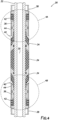
- FIG. 4 another example of the seal section 26 is representatively illustrated in an unset configuration.
- the seal section 26 includes different anti-extrusion backups 40.
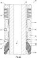
- An upper abutment 36, anti-extrusion backup 40, biasing device 42 and sleeve 44 are depicted in FIG. 4A
- a lower abutment 36, anti-extrusion backup 40, biasing device 42 and sleeve 44 are depicted in FIG. 4B .
- the anti-extrusion backup 40 includes the fold-back ring 50.
- the fold-back ring 50 has a frustoconical shape in this example and makes up a majority of the anti-extrusion backup 40.
- a thinner backup ring 58 is interposed between the fold-back ring 50 and the seal element 34.
- the backup ring 58 radially outwardly overlaps an end of the seal element 34.
- the fold-back ring 50 radially outwardly overlaps most of the backup ring 58.
- the radially inward portion 46 of the anti-extrusion backup 40 (including both of the fold-back ring 50 and the backup ring 58) is secured to the abutment 36 in this example. This ensures that the radially outward portion 48 of the anti-extrusion backup 40 will be rotated radially inward by the biasing force exerted by the biasing device 42 when the well barrier 20 is unset.
- an additional fold-back ring 60 is used.
- the fold-back ring 50 is interposed between the backup ring 58 and the fold-back ring 60.
- the shoulder 52 is formed in the fold-back ring 60. Radially inward portions of the fold-back rings 50, 60 and the backup ring 58 are all secured to the abutment 36.
- the anti-extrusion backup 40 is similar to the FIG. 4B example, in that it includes the multiple fold-back rings 50, 60 as well as the backup ring 58.
- FIGS. 6A & B another example of the seal section 26 is representatively illustrated, in respective unset and set configurations.
- the anti-extrusion backup 40 extends radially outward and the biasing device 42 is compressed when the well barrier 20 is set as depicted in FIG. 6B .
- the anti-extrusion backup 40 radially retracts, due to the compressed biasing device 42, when the well barrier 20 is unset as depicted in FIG. 6A .
- FIGS. 7A-D another example of the well barrier 20 is representatively illustrated in run-in, set, equalized and released or unset configurations. Only an upper portion of the well barrier 20 including the seal section 26 is depicted in FIGS. 7A-D .
- the anti-extrusion backups 40 are similar to that depicted in FIG. 4A .
- the well barrier 20 is suited to be conveyed into a wellbore or tubular string, which in some cases can include restrictions or obstructions. Accordingly, the seal section 26 is radially retracted, with the seal elements 34 and anti-extrusion backups 40 preferably at or below a gage diameter of the well barrier 20
- the longitudinal distance between the abutments 36 is decreased, so that the seal elements 34 are longitudinally compressed and radially outwardly extended.
- the anti-extrusion backups 40 are also radially outwardly extended, and the biasing device 42 is further compressed to thereby increase the biasing force exerted on the sleeve 44 (and the radially outward portion 48 of the backup 40).
- any pressure differential across the seal elements 34 is relieved, in preparation for unsetting the well barrier 20.
- the seal elements 34 and anti-extrusion backups 40 remain radially outwardly extended.
- FIGS. 8A & B another example of the seal section 26 is representatively illustrated in respective unset and set configurations.
- the anti-extrusion backups 40 are similar to that depicted in FIG. 4A .
- the backup 40 rotates outward (the radially outward portion 48 rotates outward relative to the radially inward portion 46, which is secured to the abutment 36).
- the backup 40 rotates inward (the radially outward portion 48 rotates inward relative to the radially inward portion 46, which is secured to the abutment 36), due to the biasing force exerted by the biasing device 42.
- the well barrier 20 includes features that enable the anti-extrusion backup 40 to be radially retracted (for example, to its initial unset configuration) prior to retrieving the well barrier from a well.
- the well barrier 20 can include an annular seal element 34, an anti-extrusion backup 40 having radially inward and radially outward portions 46, 48, and a biasing device 42 that exerts a biasing force against the radially outward portion 48 of the anti-extrusion backup 40.
- the well barrier 20 may include an abutment 36.
- the radially inward portion 46 of the anti-extrusion backup 40 may be secured against longitudinal displacement relative to the abutment 36.
- the radially outward portion 48 of the anti-extrusion backup 40 may be longitudinally displaceable relative to the abutment 36.
- the anti-extrusion backup 40 may retract radially inward in response to the biasing force applied to the radially outward portion 48 of the anti-extrusion backup 40.
- the biasing device 42 may comprise at least one Belleville spring washer.
- the biasing device 42 may exert the biasing force against a sleeve 44 reciprocably disposed relative to the anti-extrusion backup 40.
- the sleeve 44 may be reciprocably disposed relative to an abutment 36, the seal element 34 may extend radially outward in response to a compressive force applied between the abutment 36 and the seal element 34, and the sleeve 44 may surround the abutment 36.
- the anti-extrusion backup 40 may include a fold-back ring 50.
- the fold-back ring 50 may retract radially inward in response to application of the biasing force to the radially outward portion 48 of the anti-extrusion backup 40.
- the above disclosure also provides to the art a method of operating a well barrier 20.
- the method can include: setting the well barrier 20 by decreasing a longitudinal distance between first and second abutments 36 of the well barrier 20, thereby compressing a seal element 34 between the first and second abutments 36; and unsetting the well barrier 20 by increasing the longitudinal distance between the first and second abutments 36.
- the unsetting step includes radially inwardly retracting an anti-extrusion backup 40 positioned longitudinally between the seal element 34 and the first abutment 36.
- the anti-extrusion backup 40 may expand radially outward in response to the compressing of the seal element 34.
- the retracting step can include applying a biasing force to a radially outward portion 48 of the anti-extrusion backup 40.
- the biasing force applying step may include a biasing device 42 biasing a sleeve 44 to displace relative to the first abutment 36 and toward the seal element 34.
- the sleeve 44 may surround the first abutment 36.
- the setting step may include displacing the sleeve 44 relative to the first abutment 36 in a first direction
- the unsetting step may include displacing the sleeve 44 relative to the first abutment 36 in a second direction opposite to the first direction
- the setting step may include increasing the biasing force.
- the setting step may include rotating a portion of the anti-extrusion backup 40 in a first direction
- the unsetting step may include rotating the portion of the anti-extrusion backup 40 in a second direction opposite to the first direction.
- the well barrier 20 can include an annular seal element 34, an anti-extrusion backup 40, an abutment 36 displaceable relative to the seal element 34 to compress the seal element 34, a sleeve 44 reciprocable relative to the abutment 36, and a biasing device 42 that biases the sleeve 44 toward the anti-extrusion backup 40.
- a radially inward portion 46 of the anti-extrusion backup 40 may be secured relative to the abutment 36.
- the biasing device 42 may bias the sleeve 44 into contact with a radially outward portion 48 of the anti-extrusion backup 40.
- the radially outward portion 48 of the anti-extrusion backup 40 may be longitudinally displaceable relative to the abutment 36.
- the anti-extrusion backup 40 may retract radially inward in response to a biasing force applied via the sleeve 44 to the radially outward portion 48 of the anti-extrusion backup 40.
- the anti-extrusion backup 40 may include a fold-back ring 50.
- the fold-back ring 50 may retract radially inward in response to application of a biasing force to a radially outward portion 48 of the anti-extrusion backup 40.
Landscapes
- Life Sciences & Earth Sciences (AREA)
- Engineering & Computer Science (AREA)
- Geology (AREA)
- Mining & Mineral Resources (AREA)
- Physics & Mathematics (AREA)
- Environmental & Geological Engineering (AREA)
- Fluid Mechanics (AREA)
- General Life Sciences & Earth Sciences (AREA)
- Geochemistry & Mineralogy (AREA)
- Sealing Devices (AREA)
Applications Claiming Priority (3)
| Application Number | Priority Date | Filing Date | Title |
|---|---|---|---|
| US201962801496P | 2019-02-05 | 2019-02-05 | |
| PCT/US2020/016543 WO2020163301A1 (en) | 2019-02-05 | 2020-02-04 | Retrievable anti-extrusion fold-back ring backup for seal element |
| EP20709415.2A EP3921508B1 (de) | 2019-02-05 | 2020-02-04 | Rückholbarer extrusionsverhindernder rücksetzbarer reservering für dichtungselement |
Related Parent Applications (2)
| Application Number | Title | Priority Date | Filing Date |
|---|---|---|---|
| EP20709415.2A Division EP3921508B1 (de) | 2019-02-05 | 2020-02-04 | Rückholbarer extrusionsverhindernder rücksetzbarer reservering für dichtungselement |
| EP20709415.2A Division-Into EP3921508B1 (de) | 2019-02-05 | 2020-02-04 | Rückholbarer extrusionsverhindernder rücksetzbarer reservering für dichtungselement |
Publications (3)
| Publication Number | Publication Date |
|---|---|
| EP4375478A2 true EP4375478A2 (de) | 2024-05-29 |
| EP4375478A3 EP4375478A3 (de) | 2024-06-26 |
| EP4375478B1 EP4375478B1 (de) | 2025-05-28 |
Family
ID=69743951
Family Applications (2)
| Application Number | Title | Priority Date | Filing Date |
|---|---|---|---|
| EP20709415.2A Active EP3921508B1 (de) | 2019-02-05 | 2020-02-04 | Rückholbarer extrusionsverhindernder rücksetzbarer reservering für dichtungselement |
| EP24169083.3A Active EP4375478B1 (de) | 2019-02-05 | 2020-02-04 | Abrufbare antiextrusionsrückfaltringsicherung für dichtungselement |
Family Applications Before (1)
| Application Number | Title | Priority Date | Filing Date |
|---|---|---|---|
| EP20709415.2A Active EP3921508B1 (de) | 2019-02-05 | 2020-02-04 | Rückholbarer extrusionsverhindernder rücksetzbarer reservering für dichtungselement |
Country Status (6)
| Country | Link |
|---|---|
| US (2) | US11236579B2 (de) |
| EP (2) | EP3921508B1 (de) |
| AU (1) | AU2020218183B2 (de) |
| DK (2) | DK3921508T3 (de) |
| SA (1) | SA521422683B1 (de) |
| WO (1) | WO2020163301A1 (de) |
Families Citing this family (9)
| Publication number | Priority date | Publication date | Assignee | Title |
|---|---|---|---|---|
| DK3921508T3 (da) | 2019-02-05 | 2024-10-07 | Weatherford Tech Holdings Llc | Genophalelig ekstruderingsforhindrende tilbagefoldningssikkerhedsring til tætningselement |
| US11959352B2 (en) | 2020-10-30 | 2024-04-16 | Weatherford Technology Holdings, Llc | Retrievable high expansion bridge plug and packer with retractable anti-extrusion backup system |
| US11713643B2 (en) * | 2020-10-30 | 2023-08-01 | Weatherford Technology Holdings, Llc | Controlled deformation and shape recovery of packing elements |
| US11555364B2 (en) | 2020-10-30 | 2023-01-17 | Weatherford Technology Holdings, Llc | High expansion anchoring system |
| CN112838554B (zh) * | 2021-01-15 | 2022-02-15 | 西南石油大学 | 一种电潜泵电缆作业井口装置 |
| US11492869B2 (en) * | 2021-04-05 | 2022-11-08 | Baker Hughes Oilfield Operations Llc | Backup and packer |
| WO2023055513A1 (en) * | 2021-10-01 | 2023-04-06 | Weatherford Technology Holdings, Llc | Retrievable high expandsion bridge plug or packer with retractable anti-extrusion backup system |
| CA3242273A1 (en) * | 2021-12-09 | 2023-06-15 | Schlumberger Canada Limited | Packer assembly with an anti-extrusion assembly |
| US12540880B2 (en) * | 2023-01-10 | 2026-02-03 | Schlumberger Technology Corporation | Electrified sealing and anti-extrusion elements for system health monitoring |
Family Cites Families (11)
| Publication number | Priority date | Publication date | Assignee | Title |
|---|---|---|---|---|
| US3606347A (en) * | 1969-02-28 | 1971-09-20 | Dresser Ind | Wireline wipers |
| US5314014A (en) * | 1992-05-04 | 1994-05-24 | Dowell Schlumberger Incorporated | Packer and valve assembly for temporary abandonment of wells |
| US5433269A (en) * | 1992-05-15 | 1995-07-18 | Halliburton Company | Retrievable packer for high temperature, high pressure service |
| NO318363B1 (no) * | 2003-04-02 | 2005-03-07 | Bronnteknologiutvikling As | Anordning ved trekkbar broplugg |
| US7708080B2 (en) * | 2005-06-23 | 2010-05-04 | Schlumberger Technology Corporation | Packer |
| US7735568B2 (en) * | 2006-03-29 | 2010-06-15 | Schlumberger Technology Corporation | Packer cup systems for use inside a wellbore |
| US20090255690A1 (en) * | 2008-04-09 | 2009-10-15 | Baker Hughes Incorporated | Multi-Piece Packing Element Containment System |
| US8393388B2 (en) | 2010-08-16 | 2013-03-12 | Baker Hughes Incorporated | Retractable petal collet backup for a subterranean seal |
| WO2014077830A1 (en) * | 2012-11-16 | 2014-05-22 | Halliburton Energy Servcies, Inc. | Assisting retrieval of a downhole tool |
| GB2539259A (en) * | 2015-06-12 | 2016-12-14 | Rubberatkins Ltd | Improved sealing apparatus |
| DK3921508T3 (da) | 2019-02-05 | 2024-10-07 | Weatherford Tech Holdings Llc | Genophalelig ekstruderingsforhindrende tilbagefoldningssikkerhedsring til tætningselement |
-
2020
- 2020-02-04 DK DK20709415.2T patent/DK3921508T3/da active
- 2020-02-04 US US16/954,148 patent/US11236579B2/en active Active
- 2020-02-04 EP EP20709415.2A patent/EP3921508B1/de active Active
- 2020-02-04 DK DK24169083.3T patent/DK4375478T3/da active
- 2020-02-04 AU AU2020218183A patent/AU2020218183B2/en active Active
- 2020-02-04 WO PCT/US2020/016543 patent/WO2020163301A1/en not_active Ceased
- 2020-02-04 EP EP24169083.3A patent/EP4375478B1/de active Active
-
2021
- 2021-08-02 SA SA521422683A patent/SA521422683B1/ar unknown
- 2021-12-15 US US17/551,422 patent/US11993999B2/en active Active
Also Published As
| Publication number | Publication date |
|---|---|
| US11236579B2 (en) | 2022-02-01 |
| AU2020218183A1 (en) | 2021-07-15 |
| US20220106854A1 (en) | 2022-04-07 |
| WO2020163301A1 (en) | 2020-08-13 |
| DK4375478T3 (da) | 2025-08-25 |
| DK3921508T3 (da) | 2024-10-07 |
| BR112021015284A2 (pt) | 2021-10-05 |
| AU2020218183B2 (en) | 2025-05-29 |
| EP3921508B1 (de) | 2024-08-14 |
| EP4375478A3 (de) | 2024-06-26 |
| SA521422683B1 (ar) | 2023-10-04 |
| EP4375478B1 (de) | 2025-05-28 |
| US20210140265A1 (en) | 2021-05-13 |
| US11993999B2 (en) | 2024-05-28 |
| EP3921508A1 (de) | 2021-12-15 |
Similar Documents
| Publication | Publication Date | Title |
|---|---|---|
| US11993999B2 (en) | Retrievable anti-extrusion foldback-ring backup for sealing element | |
| US6840328B2 (en) | Anti-extrusion apparatus and method | |
| US8291989B2 (en) | Retrieval method for opposed slip type packers | |
| AU2015406992B2 (en) | Bidirectional slips | |
| US9714553B2 (en) | Assisting retrieval of a downhole tool | |
| EP3899196B1 (de) | Bohrwerkzeug mit hoher erweiterung und verwandte methoden | |
| US11976532B2 (en) | Slip assembly for downhole tool and method therefor | |
| CA2989109C (en) | Resettable pre-set mechanism for downhole tools | |
| WO2015016945A1 (en) | Well packer with nonrotating mandrell lock device | |
| US10329868B2 (en) | Releasably locked debris barrier for a subterranean tool | |
| EP3983641B1 (de) | Verfahren und system zur verstärkung der dichtungselemente von bohrlochbarrieren | |
| AU2012372853B2 (en) | Deactivation of packer with safety joint | |
| BR112021015284B1 (pt) | Barreira de poço e método de operação de uma barreira de poço |
Legal Events
| Date | Code | Title | Description |
|---|---|---|---|
| PUAI | Public reference made under article 153(3) epc to a published international application that has entered the european phase |
Free format text: ORIGINAL CODE: 0009012 |
|
| STAA | Information on the status of an ep patent application or granted ep patent |
Free format text: STATUS: THE APPLICATION HAS BEEN PUBLISHED |
|
| PUAL | Search report despatched |
Free format text: ORIGINAL CODE: 0009013 |
|
| AC | Divisional application: reference to earlier application |
Ref document number: 3921508 Country of ref document: EP Kind code of ref document: P |
|
| AK | Designated contracting states |
Kind code of ref document: A2 Designated state(s): AL AT BE BG CH CY CZ DE DK EE ES FI FR GB GR HR HU IE IS IT LI LT LU LV MC MK MT NL NO PL PT RO RS SE SI SK SM TR |
|
| AK | Designated contracting states |
Kind code of ref document: A3 Designated state(s): AL AT BE BG CH CY CZ DE DK EE ES FI FR GB GR HR HU IE IS IT LI LT LU LV MC MK MT NL NO PL PT RO RS SE SI SK SM TR |
|
| RIC1 | Information provided on ipc code assigned before grant |
Ipc: E21B 33/12 20060101AFI20240522BHEP |
|
| STAA | Information on the status of an ep patent application or granted ep patent |
Free format text: STATUS: REQUEST FOR EXAMINATION WAS MADE |
|
| GRAP | Despatch of communication of intention to grant a patent |
Free format text: ORIGINAL CODE: EPIDOSNIGR1 |
|
| STAA | Information on the status of an ep patent application or granted ep patent |
Free format text: STATUS: GRANT OF PATENT IS INTENDED |
|
| 17P | Request for examination filed |
Effective date: 20241126 |
|
| RBV | Designated contracting states (corrected) |
Designated state(s): AL AT BE BG CH CY CZ DE DK EE ES FI FR GB GR HR HU IE IS IT LI LT LU LV MC MK MT NL NO PL PT RO RS SE SI SK SM TR |
|
| INTG | Intention to grant announced |
Effective date: 20241223 |
|
| GRAS | Grant fee paid |
Free format text: ORIGINAL CODE: EPIDOSNIGR3 |
|
| GRAA | (expected) grant |
Free format text: ORIGINAL CODE: 0009210 |
|
| STAA | Information on the status of an ep patent application or granted ep patent |
Free format text: STATUS: THE PATENT HAS BEEN GRANTED |
|
| AC | Divisional application: reference to earlier application |
Ref document number: 3921508 Country of ref document: EP Kind code of ref document: P |
|
| AK | Designated contracting states |
Kind code of ref document: B1 Designated state(s): AL AT BE BG CH CY CZ DE DK EE ES FI FR GB GR HR HU IE IS IT LI LT LU LV MC MK MT NL NO PL PT RO RS SE SI SK SM TR |
|
| REG | Reference to a national code |
Ref country code: GB Ref legal event code: FG4D |
|
| REG | Reference to a national code |
Ref country code: CH Ref legal event code: EP |
|
| REG | Reference to a national code |
Ref country code: DE Ref legal event code: R096 Ref document number: 602020052153 Country of ref document: DE |
|
| REG | Reference to a national code |
Ref country code: IE Ref legal event code: FG4D |
|
| REG | Reference to a national code |
Ref country code: NL Ref legal event code: FP |
|
| REG | Reference to a national code |
Ref country code: DK Ref legal event code: T3 Effective date: 20250822 |
|
| PG25 | Lapsed in a contracting state [announced via postgrant information from national office to epo] |
Ref country code: FI Free format text: LAPSE BECAUSE OF FAILURE TO SUBMIT A TRANSLATION OF THE DESCRIPTION OR TO PAY THE FEE WITHIN THE PRESCRIBED TIME-LIMIT Effective date: 20250528 Ref country code: ES Free format text: LAPSE BECAUSE OF FAILURE TO SUBMIT A TRANSLATION OF THE DESCRIPTION OR TO PAY THE FEE WITHIN THE PRESCRIBED TIME-LIMIT Effective date: 20250528 |
|
| REG | Reference to a national code |
Ref country code: LT Ref legal event code: MG9D |
|
| PG25 | Lapsed in a contracting state [announced via postgrant information from national office to epo] |
Ref country code: GR Free format text: LAPSE BECAUSE OF FAILURE TO SUBMIT A TRANSLATION OF THE DESCRIPTION OR TO PAY THE FEE WITHIN THE PRESCRIBED TIME-LIMIT Effective date: 20250829 |
|
| PG25 | Lapsed in a contracting state [announced via postgrant information from national office to epo] |
Ref country code: PL Free format text: LAPSE BECAUSE OF FAILURE TO SUBMIT A TRANSLATION OF THE DESCRIPTION OR TO PAY THE FEE WITHIN THE PRESCRIBED TIME-LIMIT Effective date: 20250528 |
|
| PG25 | Lapsed in a contracting state [announced via postgrant information from national office to epo] |
Ref country code: BG Free format text: LAPSE BECAUSE OF FAILURE TO SUBMIT A TRANSLATION OF THE DESCRIPTION OR TO PAY THE FEE WITHIN THE PRESCRIBED TIME-LIMIT Effective date: 20250528 |
|
| PG25 | Lapsed in a contracting state [announced via postgrant information from national office to epo] |
Ref country code: HR Free format text: LAPSE BECAUSE OF FAILURE TO SUBMIT A TRANSLATION OF THE DESCRIPTION OR TO PAY THE FEE WITHIN THE PRESCRIBED TIME-LIMIT Effective date: 20250528 |
|
| PG25 | Lapsed in a contracting state [announced via postgrant information from national office to epo] |
Ref country code: RS Free format text: LAPSE BECAUSE OF FAILURE TO SUBMIT A TRANSLATION OF THE DESCRIPTION OR TO PAY THE FEE WITHIN THE PRESCRIBED TIME-LIMIT Effective date: 20250828 |
|
| PG25 | Lapsed in a contracting state [announced via postgrant information from national office to epo] |
Ref country code: IS Free format text: LAPSE BECAUSE OF FAILURE TO SUBMIT A TRANSLATION OF THE DESCRIPTION OR TO PAY THE FEE WITHIN THE PRESCRIBED TIME-LIMIT Effective date: 20250928 |
|
| PG25 | Lapsed in a contracting state [announced via postgrant information from national office to epo] |
Ref country code: LV Free format text: LAPSE BECAUSE OF FAILURE TO SUBMIT A TRANSLATION OF THE DESCRIPTION OR TO PAY THE FEE WITHIN THE PRESCRIBED TIME-LIMIT Effective date: 20250528 |
|
| REG | Reference to a national code |
Ref country code: AT Ref legal event code: MK05 Ref document number: 1798693 Country of ref document: AT Kind code of ref document: T Effective date: 20250528 |
|
| PGFP | Annual fee paid to national office [announced via postgrant information from national office to epo] |
Ref country code: GB Payment date: 20251211 Year of fee payment: 7 |
|
| PG25 | Lapsed in a contracting state [announced via postgrant information from national office to epo] |
Ref country code: SM Free format text: LAPSE BECAUSE OF FAILURE TO SUBMIT A TRANSLATION OF THE DESCRIPTION OR TO PAY THE FEE WITHIN THE PRESCRIBED TIME-LIMIT Effective date: 20250528 Ref country code: AT Free format text: LAPSE BECAUSE OF FAILURE TO SUBMIT A TRANSLATION OF THE DESCRIPTION OR TO PAY THE FEE WITHIN THE PRESCRIBED TIME-LIMIT Effective date: 20250528 |
|
| PGFP | Annual fee paid to national office [announced via postgrant information from national office to epo] |
Ref country code: NL Payment date: 20251215 Year of fee payment: 7 |
|
| PG25 | Lapsed in a contracting state [announced via postgrant information from national office to epo] |
Ref country code: CZ Free format text: LAPSE BECAUSE OF FAILURE TO SUBMIT A TRANSLATION OF THE DESCRIPTION OR TO PAY THE FEE WITHIN THE PRESCRIBED TIME-LIMIT Effective date: 20250528 |
|
| PG25 | Lapsed in a contracting state [announced via postgrant information from national office to epo] |
Ref country code: EE Free format text: LAPSE BECAUSE OF FAILURE TO SUBMIT A TRANSLATION OF THE DESCRIPTION OR TO PAY THE FEE WITHIN THE PRESCRIBED TIME-LIMIT Effective date: 20250528 |
|
| PG25 | Lapsed in a contracting state [announced via postgrant information from national office to epo] |
Ref country code: SK Free format text: LAPSE BECAUSE OF FAILURE TO SUBMIT A TRANSLATION OF THE DESCRIPTION OR TO PAY THE FEE WITHIN THE PRESCRIBED TIME-LIMIT Effective date: 20250528 |
|
| REG | Reference to a national code |
Ref country code: DE Ref legal event code: R097 Ref document number: 602020052153 Country of ref document: DE |
|
| PLBE | No opposition filed within time limit |
Free format text: ORIGINAL CODE: 0009261 |
|
| STAA | Information on the status of an ep patent application or granted ep patent |
Free format text: STATUS: NO OPPOSITION FILED WITHIN TIME LIMIT |
|
| REG | Reference to a national code |
Ref country code: CH Ref legal event code: L10 Free format text: ST27 STATUS EVENT CODE: U-0-0-L10-L00 (AS PROVIDED BY THE NATIONAL OFFICE) Effective date: 20260409 |
|
| PGFP | Annual fee paid to national office [announced via postgrant information from national office to epo] |
Ref country code: NO Payment date: 20260211 Year of fee payment: 7 Ref country code: DK Payment date: 20260213 Year of fee payment: 7 |
|
| PGFP | Annual fee paid to national office [announced via postgrant information from national office to epo] |
Ref country code: IT Payment date: 20260122 Year of fee payment: 7 |