EP4375436A1 - A panel for forming attenuation crates - Google Patents
A panel for forming attenuation crates Download PDFInfo
- Publication number
- EP4375436A1 EP4375436A1 EP22209939.2A EP22209939A EP4375436A1 EP 4375436 A1 EP4375436 A1 EP 4375436A1 EP 22209939 A EP22209939 A EP 22209939A EP 4375436 A1 EP4375436 A1 EP 4375436A1
- Authority
- EP
- European Patent Office
- Prior art keywords
- panel
- panels
- attenuation
- crate
- notch
- Prior art date
- Legal status (The legal status is an assumption and is not a legal conclusion. Google has not performed a legal analysis and makes no representation as to the accuracy of the status listed.)
- Pending
Links
Images








Classifications
-
- E—FIXED CONSTRUCTIONS
- E03—WATER SUPPLY; SEWERAGE
- E03F—SEWERS; CESSPOOLS
- E03F1/00—Methods, systems, or installations for draining-off sewage or storm water
- E03F1/002—Methods, systems, or installations for draining-off sewage or storm water with disposal into the ground, e.g. via dry wells
- E03F1/005—Methods, systems, or installations for draining-off sewage or storm water with disposal into the ground, e.g. via dry wells via box-shaped elements
Definitions
- the present invention relates to attenuation crates, and in particular modular attenuation crate systems for installing underground to dispose of unwanted water such as surface run-off.
- An attenuation crate is a type of dry well or underground structure that disposes of unwanted water.
- This unwanted water typically comprises surface runoff which is the flow of water occurring on the ground surface when excess rainwater, stormwater, or even meltwater, cannot rapidly infiltrate in the soil. This often occurs when the soil is saturated by water to its full capacity. Sometimes rainfall is heavy, and the soil cannot absorb it quickly enough.
- Surface runoff can often occur because of impervious areas, such as pavements, hard-standings and patios. These man-made structures prevent water from soaking into the ground.
- Surface runoff is a major component of the water cycle. In areas where its natural flow is affected it can cause significant soil erosion, and by carrying contaminants such as rotting leaves, pesticides, fertilizers, it can also cause pollution.
- Attenuation crates are passive structures that are embedded in the ground. Surface runoff flows through these crates under the influence of gravity.
- Each crate typically comprises a framework, made from concrete, plastic or otherwise, that is covered by a porous material to prevent the ingress of soil.
- the framework defines a large interior storage volume with perforated sides and base. These porous-walled chambers allow water to slowly soak into the ground, dissipating into the groundwater.
- Such structures are also known as soakaway crates.
- these crates can prove to be a highly effective way of dealing with surface water. They collect all surface water run-off into one point before allowing it to percolate in a controlled manner into the surrounding ground in the area where it falls.
- Soakaway crates allow levels of surface water to be controlled. This prevents flooding during heavy rainfall and helps to deal with excess water in situations where the volume of water is too high for existing surface water drainage systems to cope with. Consequently, soakaway crates can be used in both commercial and domestic situations.
- Some existing attenuation or soakaway crates are not modular, and can cost a considerable amount to manufacture, store and ship. Those that are modular in some way often require a complex assembly process, with additional fasteners or component parts to hold the structure together or link to other adjacent crates.
- GB 2 444 550 (Source Control Systems Ltd ) discloses a modular storage system, primarily for use underground.
- the storage system is formed from two different types of panel.
- WO2010/009410 discloses a modular water retention structure.
- a panel for forming an interlocking attenuation crate comprising: a substantially square planar body with at least one aperture to enable through passage of fluid; the panel has first and second adjacent sides each having first interlocking features comprised of at least one tab and at least two notches; and third and fourth adjacent sides with a second arrangement of interlocking features comprised of at least two tabs and at least one notch; wherein the tabs and notches of the first and second interlocking features are adapted to engage with each other and at least one tab of the first interlocking features is tapered and is adapted to be received by at least one corresponding tapered notch on the second interlocking features providing a mechanical interference fit to enable releasable connection of panels to form a six sided attenuation crate.
- Six panels can be arranged to form an attenuation crate wherein sides of the panels are adapted to releasably secure to each other to form a cube configuration that is an attenuation crate defining an interior volume.
- Attenuation crates can be readily assembled and positioned for use. Furthermore two or more attenuation crates can be joined together using integral clip features (attachment means) to increase the drainage provided.
- the unassembled dimensions of the attenuation crate enable the panels may be stacked, the number of different components parts is as few as possible and the panels interlock, without need for any additional fasteners.
- each panel forming the attenuation crate is identical.
- tapered tabs and notches means that panels are prevented or at least restricted from pulling a part. This is achieved by a tapered tab tapering from a distal end to a proximal end, and a tapered notch tapering from a proximal end to a distal end and/or a tab or a notch tapered from a first face to a second opposed face.
- the tapering may be provided in two orthogonal planes to reflect the orthogonal attachment of adjacent panels, one to another so that tapered tabs are held within the tapered notches.
- the first arrangement of interlocking features comprises a central tab with a notch on either side of said central tab
- the second arrangement of interlocking features comprise a central notch with a tab on either side of said central notch.
- the first and second interlocking parts correspond to each other so that notches of one panel receive tabs of another panel and vice-versa in order to form an interlocking connection.
- a first or second side of a first panel with the first arrangement of tabs and notches that are the first interlocking features are configured to interlock with a third or fourth side of a second panel provided with the second complementary arrangement of tabs and notches.
- Third or fourth sides of a first panel with the second arrangement of interlocking features comprising tabs and notches are configured to interlock with first or second sides of a second panel provided with the complementary arrangement of first interlocking features.
- the first and second interlocking features interlock at interlocking regions. In this way the panels can be aligned and interlocked by engagement of the first and second interlocking features to form a cube configuration.
- the tabs extend from a side edge of the panels and are adapted to engage with corresponding notches (tapered or non-tapered).
- the notches are recesses defined in a side edge of the panels and are adapted to engage with corresponding tabs.
- each panel side includes at least one slot on one edge of the panel and at least one projection on a different edge of the panel that engage to provide a releasable locking means.
- the projection of a first panel is received by the slot of a second panel as a further interlocking connection that is a releasable locking means in addition to the engagement of tabs and notches.
- the central tab incorporates the slot
- the central notch incorporates the projection, such that, in use, the projection is configured to fit within the slot for releasably securing the panels to one another to form a cube configuration.
- the slot and projection thereby providing a second means of connection that is in addition to the interlocking features of the tabs and notches.
- Each panel has two sides incorporating the first arrangement of tabs and notches (first interlocking means), and two sides incorporating the second complementary arrangement of tabs and notches (second interlocking means), where each side incorporating the first arrangement is opposite each side incorporating the second complementary arrangement.
- first interlocking means two sides incorporating the first arrangement of tabs and notches
- second interlocking means two sides incorporating the second complementary arrangement of tabs and notches
- Each panel has at least one corner tab and at least one corresponding corner notch.
- a corner includes both a tab and a notch referred to as a part corner.
- a first pair of opposed corners have a corner tab diagonally opposed to a corner notch
- the second pair of opposed corners have part corners that each have a tab portion and a notch portion.
- the tabs and notches of the first interlocking features are identical on both sides.
- the tabs and notches of the second interlocking features are also identical on both sides of the panel.
- the sides of each side of the panel are different at every corner due to the profile of each corner. Therefore the profile of each side is different due to the shape of the corners.
- notches or tab and notch is different along each corner edge.
- the corner tab has one tab edge longer than the other
- the corner notch has one notch edge longer than the other and both part corners have a notch that is longer than the tab.
- the corner profiles are adapted to enable connection of the panels that form a flush outer surface.
- first and second sides with the first arrangement of interlocking features join at the corner tab and the third and fourth panel edges with the second interlocking features join at the corner notch.
- second and third panel edges and fourth and first panel edges join by part corners.
- the corner tab associated with the first and second sides of the panels is substantially arrow shaped tab, which when bisected on the diagonal defines different shaped corner tabs as each tab edge is of a different length.
- the shape of the corner tab can be considered an orientation indicator to help with assembly as the arrow shape is easily visible and is associated with indicating direction.
- each panel may incorporate alignment indicia for orientating each panel with respect to another panel to form the cube configuration.
- the arrow shaped corner tab may be used as an alignment indicium as it is distinguishable from all other corners and assists with determining orientation of each panel during assembly.
- the alignment indicia may comprise a cut-out in a face of the panel or an embossed or debossed portion on the face of the panel.
- the cut-out, embossed or debossed portion may comprise an arrow shape.
- an outer face of the panel may comprise attachment means for releasably securing to a corresponding attachment means in the outer face of another panel, such that, in use, the cube configuration of panels is releasably secured to a neighbouring cube configuration of said panels.
- the attachment means are a form of integral clip mechanism that enables adjacent crates to be easily connected.
- the attachment means may comprise a plurality of raised portions adapted to engage with a corresponding plurality of lowered portions. For example a plurality of ribs may be received to a plurality of grooves.
- the panel comprises a one-piece plastics material.
- the panel may be formed by injection moulding.
- each panel is adapted to receive an internal support between at least two opposed panels to provide additional strength to the attenuation crate when assembled.
- the internal support enhances compression resistance of the attenuation crate.
- the internal support is a tube that engages with an internal face of the panel.
- the tube end may be received into a recess on an internal face of each panel, or the tube end may include a recess that is received onto a projection, or series of projections on the panel.
- the internal support may include engagement means for connection with the panel, such as a twist lock, or resiliently deformable portions.
- the internal support may be a multi-way support that engages with at least two pairs of opposed faces. In this way the compressive strength of the attenuation crate is enhanced.
- the internal support has six points of engagement so that the internal support has a plurality of arms that engage with an aperture on every panel.
- a preferred method of fitting the multi-way internal support is to assemble five sides of the attenuation crate and insert the multi-way support so that ends of the internal support that engage with the side panels are offset from the engagement locations. This allows the multi-way support to be engaged with the lower panel and then twisted to engage the side nodes into the central aperture of each panel. It is appreciated that the side walls will flex during the process in order to permit engagement. Once in position the upper panel can be added.
- the internal support may be formed as a single part or may be formed from two or more parts.
- the internal support may be a straight tube arranged between two opposed faces of the attenuation crate.
- the international support may be formed from two halves that together form a tube. The tube being formed from two or more parts may reduce costs for manufacturing purposes. The two halves may be connected by an attachment means such as inter-engaging clips.
- the attenuation crate may be wrapped with a membrane or porous material to prevent build-up of solid material within the crate.
- each panel is in the range of 450mm to 550mm by 450mm to 550mm and preferably within the range of 480mm to 500mm by 480mm to 500mm.
- a typical attenuation crate 1 comprises an internal volume of 0.125m 3 .
- a method of assembling an attenuation crate from six panels comprising the steps of: interlocking four panels together to form four sides of a cube configuration with four interlocking regions, whereby at two of the interlocking regions one panel is rotated through 90 degrees about their centre for alignment with a neighbouring panel, and at the two other interlocking regions both panels are arranged in the same orientation; each panel is releasably secured at right angles to said neighbouring panel at an interlocking region; and mounting a further panel on either end to form a top and a bottom of the cube configuration.
- Figure 1 shows an attenuation crate 1 for use underground, as a structure for attenuating and slowly disposing of unwanted water such as surface runoff.
- the attenuation crate 1 comprises six identical panels 2, where each panel 2 is configured to interlock with neighbouring panels 2 to form a cube configuration that creates an internal volume.
- the panels 2 are identical, such that they may be formed from the same tooling, greatly reducing manufacturing costs.
- Each panel 2 may comprise a plastic material and each panel 2 may have been formed through injection moulding.
- the panels 2 may be substantially identical, in that there may be very small deviations that occurred during the manufacturing process.
- Each panel 2 has four edges, A, B, C and D.
- Each panel 2 incorporates at least one aperture 3 that allows for the passage of fluid through the attenuation crate 1.
- the panels 2 interlock through a series of tabs 4, 17 and notches 5,18, such that when the panels 2 are aligned in such a way as to form a cube shape where tabs 4, and notches 5, along a first and second side 19 of a first panel 2 correspond with tabs 17 and notches 18alon a third and fourth side 13 of a second panel 2.;.
- the tabs 4, 17 and notches 5, 18 are tapered to provide a mechanical interference connection that helps to prevent a tab 4, 17 being pulled out from a notch 5, 18.
- the tabs 4, 17 and notches 5, 18 taper in two different planes.
- the central tab 4 tapers from a distal end 4A to a proximal end 4B.
- the corresponding notch 18 tapers from an outer face 18A to an inner face 18B.
- each panel 2 Since the panels 2 are identical to one another, in order for tabs 4, 17 to align with corresponding notches 5, 18, the panels 2 must be aligned in a specific orientation to one another. To connect some of the panels a first panel 2 is rotated through an angle of 90 degrees before interconnecting this panel 2 at right angles to a neighbouring panel 2. To support the process of aligning and interconnecting of panels 2 that make up the attenuation crate 1, an outer face 16 of each panel 2 has alignment indicia 6.
- the pictured alignment indicia 6 comprise a cut-out on or within the outer face 16. The cut-out comprises a square shape.
- the outer face 16 of the panel 2 also incorporates branding indicia 7, where the branding indicia 7 is formed with cut-outs into the face outer 16. It is appreciated that the branding indicia may also serve as an alignment indicium.
- the branding indicia 7 and/or alignment indicia 6 may form part of the mould.
- the branding indicia 7 and/or alignment indicia 6 may also be applied to the outer face 16 of the panel 2 as adhesive stickers, or through printed or painted means.
- the branding indicia 7 and/or alignment indicia 6 are created as cut-outs within the outer face 16, they also take on the role as drainage apertures 3 for the passage of fluid through the attenuation crate 1.
- the outer face 16 of the panels 2 incorporate attachment means 8A, 8B, 8C, 8D such that neighbouring attenuation crates 1 can be interlocked together to form an array or grid.
- a number of attenuation crates 1 can be interlocked together to provide sufficient drainage for a specific situation. They may be interlocked side-by-side, or interlocked with one above another, to cover a predetermined area, and to fit within a hole that has been dug underground where improved drainage of water is required.
- Figure 2 shows an inside face 21 of a panel 2, showing one embodiment of a series of tapered tabs 4 and tapered notches 5. Tapered notches 5 and tapered tabs 4 on sides A and B (first and second sides 19) are tapered to prevent connected panels being pulled part once engaged.
- two sides 19 incorporate a central tab 4, with a notch 5 on either side of the central tab 4.
- Opposite sides 13 (C, D) of the same panel 2 incorporate a central notch 18 with a tab 17 on either side of the central notch 18.
- This pairing of opposite sides 13 (C, D), 19 (A, B) are configured such that the central tab 4, interconnects with the central notch 18, and likewise the notches 5 on either side of the central tab 4 correspond to the side tabs 17.
- This pairing of corresponding or complementary sides 13,19 enables assembly that makes up the square attenuation crate 1.
- the branding indicia 7 helps with the positioning of the panel 2 and determining which face of the panel 2 is to be configured on the inside surface of the attenuation crate 1, and which face is to be positioned to be on the outside surface of the attenuation crate 1.
- Figure 2 also shows one possible arrangement of corners 9, 9A, 9B 10, 10A, 10B, 11, 11A, 11B, 12, 12A, 12B of the panel 2.
- the dimensions of each corner are different to enable connection of adjacent panels 2.
- the panel 2 comprises a corner tab 9, that projects from the corner of the panel 2 where both sides 19 join.
- the corner tab 9 associated with the two sides 19 of the panels 2 is a substantially arrow shaped tab 9 which when bisected on the diagonal 'Y' defines different shaped corner tabs portions 9A, 9B for each of the two sides 19.
- the corner tab 9 has a long corner edge 9A and a shorter corner edge 9B. Part of the corner forms an edge of the notch 5.
- Corner notch 10 Diagonally opposite the corner tab 9, along line 'Y' is a corner notch 10, that indents from the corner creating a notch at the corner 10 where both sides 13 join. Corner notch 10 has a longer notch 10A on one edge and a shorter notch 10B on the other edge.
- the other two corners 11, 12 of the panel 2 along line 'X' that are opposite one another are part corners that incorporate part corner tabs 11B, 12B and part corner notches 11A, 12A.
- Part corner 11 has a longer notch 11A and a shorter tab 11B.
- Part corner 12 has the same configuration with a longer notch 12A and a shorter tab 12B.
- Part corners 11 and 12 differ slightly from each other as the notch 11A and tab 11B of part corner 11 are longer than the notch 12A and tab 12B of part corner 12. The difference enables the panels to be assembled as an attenuation crate having substantially flush joining edges.
- a first pair of opposed corners along line 'Y' have a corner tab 9 diagonally opposed to a corner notch 10, and the second pair of opposed corners along line 'X' each have a tab portion 11A, 12A and a notch portion 12A, 12B.
- Any corner including a tab portion (9, 11 and 12) has an end region that is of a lesser depth than the rest of the panel, allowing an adjacent panel to be received and form a substantially flush outer face (see Figure 4A and Figure 6 ).
- the central tabs 4 incorporate a slot 14, and the central notches 18 incorporate a projection 15 that corresponds with the slot 14.
- the projection 15 is also engaged with the slot 14, thereby providing two separate means to secure the panels together.
- the projection 15 and slot 14 are configured such that when they are engaged, they help to prevent any movement of a panel 2 with respect to the adjoining panel 2, and therefore help to increase the rigidity of the attenuation crate 1.
- cut-out regions 20 Either side on the projection 15 there are cut-out regions 20 (See Figure 6 ).
- the cut-out regions 20 allow the projection 15 to flex which assists with assembly and disassembly.
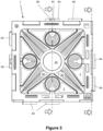
- Figure 3 shows an outer face 16 of a partially assembled attenuation crate 1 with a central cross section line V-V and an edge cross section line W-W. As the crate is assembled, parts of the rear panel are shown through the apertures 3C that do not have a mesh region that partially covers the aperture. Apertures 3C have no mesh to enable insertion of the raised region of apertures 3B of another adjacent crate to achieve the attachment means 8A, 8B, 8C, 8D further described below.
- apertures 3B offer a visual guide when assembling to another adjacent crate, thereby providing another alignment indicia. For example, consideration of apertures with mesh (3B) and apertures without mesh 3C will aid orientation of adjacent crates correctly to each other.
- Figures 4 shows cross section line V-V.
- Figures 4B and 4C show the projection 15 received in the slot 14.
- the central tab 4 of one panel engages with the central notch 18 of a second panel by means of a projection 15 received through slot 14.
- Figure 5 shows cross section W-W of Figure 3 . Engagement of every tab 4, 17 and notch 5, 18 is shown, as well as engagement of the projections 15 and slots 14.
- Figure 6 shows an outer face 16 of a single panel 2 in the centre, shown as a working drawing with end views of each side 13, 19 of the panel 2.
- the end views help to show the configuration of tabs 4 and notches 5, along with the slots 14 and projections 15 within the central tab 4 and central notch 18.
- the end of each panel that has a corner 9 or part corner 11, 12 has a shallower depth that the notch corner 10. The arrangement ensures the panels can connect to provide a flush external finish.
- Figure 7 shows a close up of the engagement between tabs 17 and a corresponding notch 5.
- a close up of where the notch 5 and tab 17 engage shows a curved finish to all edges of the tabs 17 and notches 5.
- the edges are rounded to provide an arcuate finish which assists with ease of assembly of panels. Additionally the inclusion of curved edges enables safe handling of the parts during assembly since there are no sharp regions and avoidance of sharp corners is also preferred where tooling feasibility permits.
- FIGS 8 to 14 show the stages taken to assemble the attenuation crate 1, when made from six substantially identical panels 2.
- Each of the six panels 2A, 2B, 2C, 2D, 2E, 2F has four edges, A, B, C and D.
- panel edges A, B have side configurations 19.
- Panel edges C, D have side configurations 13.
- a first panel 2A is mounted to a second panel 2B where the central tapered tab 4 of the second panel 2B is interlocked with the central tapered notch 18 of the first panel 2A, and the slot 14 of the second panel 2B engages with the projection 15 of the first panel 2A.
- Both panels 2A and 2B are in the same orientation having the branding indica 7 in the same orientation on both panels.
- the third panel 2C has been rotated through an angle of 90 degrees as indicated by the arrow and shown by the position of the branding indicia 7, so that the face 16 of the third panel 2C is orientated at 90 degrees anti-clockwise to the face 16 of the first and second panels 2A, 2B.
- Edge B of panel 2C joins to edge C of panel 2B.
- the alignment indicia 6, shown as a cut-out square, of panels 2B and 2C are arranged next to each other in the same corner of the face 16 of the panel 2.
- Figure 10 shows the four panels 2A, 2B, 2C, 2D that make up the sides of the cube all in position.
- the fourth panel 2D is mounted next to the third panel 2C and the first panel 2A to complete the sides to the cube.
- Panel edge B of panel 2D is joined to panel edge D of panel 2C.
- the fourth panel 2D has been mounted in the same orientation as the third panel 2C, with the alignment indicia 6, branding indicia 7 on both the third and fourth panels 2C, 2D in the same positions. Therefore panels 2A and 2B are in arranged in the same orientation to each other, as are panels 2C and 2D.
- the resulting cube shown in Figures 10 and 11 without top or bottom, comprises two adjacent panels 2A and 2B in the same orientation comprising central tab 4 pointing in the same direction, and the other two adjacent panels 2C, 2D both in the same orientation as each other comprising central notches 18 in the same upright configuration.
- FIG. 11 Arrows on Figure 11 indicate direction of how panel 2D is slid into position so that tapered tabs 4 on edge D are received by notched on edge A of panel 2A.
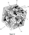
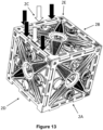
- Figures 12 and 13 show the fifth panel 2E or top panel as depicted in the Figures being applied to the side panels 2A, 2B, 2C, 2D, with the central tabs 4 being aligned with the central notches 18.
- the black arrows indicate direction of engagement of the tapered tabs 4 on panels 2A and 2B that require engagement by horizontally sliding the tabs 4 into the notches 5 which simultaneously enables the projections 15 of the top panel 2E to be received in the slots 14 of the side panels 2A and 2B as indicated by the white arrows.
- the arrows indicate that after the panel 2E has been engaged with the tapered slots and notches as shown in Figure 12 , the sides of panel 2E that engage with panels 2C and 2D require a downward force as shown by the arrows to complete engagement.
- the black arrows indicate engagement between the tapered tabs in 4 and tapered notches 5 and the white arrows indicate how projections 15 of 2D and 2C are received in slots 14 of panel 2E.
- Figures 12 and 13 therefore show the multi-step engagement of the fifth panel 2E to the sides 2A, 2B, 2C, 2D. It is appreciated that the fifth panel 2E is expected to be flexed during this engagement.
- Figure 5 shows all of the tabs 4, 17 engaging with the notches 5, 18 and the slots 14 engaging with the projections 15, to secure all six panels 2 together.
- the flexibility of the plastics material from which the panels 2 have been formed, allows for some pressure to be exerted to ensure that the tabs 4 and notches 5, and the projections 15 and slots 14 are aligned and fully engaged.
- the attenuation crate 1 forms a cube creating a space or volume therebetween.
- Several attenuations crates 1 may be required to cover an area of ground, and therefore as many attenuation crates 1 as required may be mounted alongside one another.
- the fifth and sixth panels may not fit together with the four already assembled wall panels without flexing of one or more of the panels during fitting to allow projections/slots, tabs/notches to align correctly making a very rigid structure. It is therefore important that a suitable plastic material grade is used to enable flexing during fitting.
- Figure 15 shows an example of an attenuation crate 1 with an internal support 30.
- the internal support 30 is a tube that is fitted to opposed panels in an interference condition to prevent accidental movement or displacement.
- the tube 30 has a number of 31 holes to permit passage of liquid.
- the pictured internal support 30 is formed from two parts 32, 33 (see Figure 16 ). The two parts are assembled together prior to fitting within the attenuation crate.
- the two parts 32, 33 are identical, preferably formed from synthetic plastic mouldings that slide together and assemble flush at both ends to form a complete tube.
- the pictured embodiment is formed from two half cylinder sections 32, 33, each part having a first edge with a lip 34 and a second edge with a series of C-shaped brackets 35.
- a lip 34 of a first part 32 is received by the brackets 35 of a second part 33; and a lip 34 of the second part 33 is received by the C-shaped brackets 35 of the first part 32; so as to interlock the two parts 32, 33 by sliding the parts together.
- Ends of the internal support 30 include a collar 39 that engages with the aperture 3A to locate and fix the internal support to the panel.
- Arrows 36 on an outer face of the internal support 30 indicate the sliding direction of the parts 32, 33 during assembly, thereby providing a visual aid to a person performing the assembly of the internal support 30.
- the C-shaped brackets 35 each have a block 38 that engages with a depression 37 provided on the lip 34 so that the parts 32, 33 are slid together, the blocks 38 and depressions 37 are aligned and forced together so that the parts 32, 33 are locked together and further sliding is prevented.
- Figure 17 shows a partially assembled attenuation crate 1 with 5 assembled panels 2.
- a first end of the internal support 30 is received in a central aperture 3A of the panel 2.
- the support 30 can be inserted vertically inside the crate at this stage (as shown in Figure 17 ).
- the internal support 30 can be inserted horizontally in the partially assembled crate by flexing two opposite side panels apart slightly to accept ends of the internal support 30.
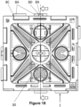
- Figure 18 shows a side view of the attenuation crate 1 with the internal support 30.
- the internal support 30 has a collar 39 (see Figure 19 ) concentric to the central aperture 3A on two opposed panels.
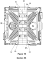
- Figure 19 shows a cross section of an attenuation crate 1 with an internal support 30.
- the internal support 30 can be arranged across any of the three opposed panels 2.
- the internal support 30 may be positioned where the greatest compressive forces are expected to be experienced. Due to the required steps of assembly to form a crate 1, by joining four side panels 2 first and then adding top and bottom panels 2, where the internal support is vertical it can be positioned when five panels are connected and then engaged with the sixth panel as it is located.
- the internal support 30 is fitted horizontally with respect to the fifth and sixth panels the sides must be flexed to enable to collar 39 to be received concentrically over the edges of the central apertures 3A of opposed side panels. It is appreciated that in some embodiments the collar may fit concentrically within the central aperture 3A.
- Figures 20 to 23 show one possible embodiment of attachment means 8 to releasably secure one attenuation crate 1 to a neighbouring attenuation crate 1.
- the attachment means 8A, 8B, 8C,8D shown comprises two of the apertures 3B having walls 8A projecting outward that are received in apertures 3C of an adjoining panel. Apertures 3B have mesh partially closing the opening. Apertures 3C are open with no mesh.
- the orientation of the attachment means 8 ensures that where attenuation crates 1 are placed side by side, or one on top of another, the circular walls 8A extending from apertures 3B from the outer face 16 of one of the panels 2 can be aligned with the apertures 3C on the outer face 16 of another one of the panels 2, such that the attachment means 8 interlocks.
- Figure 20 shows two attenuation crates 1 joined together through the attachment means 8 in a side by side configuration.
- Each panel has a range of different apertures 3A, 3B, 3C that comprise a central aperture 3A with an array of surrounding apertures 3B, 3C and mesh regions 3D to permit flow of liquid, such as rainwater (see Figure 6 ).
- the mesh regions 3D also improves strength of the panels 2.
- each outer face 16 of a panel 2 has two apertures 3B which include a circular wall 8A that projects from the outer face 16.
- the wall 8A provides attachment means 8 for engagement with an aperture 3C of an adjacent panel.
- the walls 8A are received in apertures 3C.
- the wall 8A includes a node 8C on a resiliently deformable arm 8D (see Figures 21 ) that engages with a recess 8E of the rim 8B of aperture 3B (see Figures 22 ) so that adjacent panels 2 are joined together to form an array or attenuation crates.
- the resiliently deformable arm 8D is deformed to enable the node 8C to pass through the rim to the recess 8E where the node 8B is released to engage with the recess 8B, thereby preventing separate of adjacent panels 2 without depression of the node 8C to disengage if from the recess 8B (See Figures 22 and 23 ).
- Figures 24A and 24B show a multi-way internal support 30 arranged in a partially assembled attenuation crate 1.
- the multi-way support 30 has six arms 40 that each have a collar end 39 that is received by a central aperture 3A of a panel 2.
- the attenuation crate 1 has 5 panels assembled and the internal support 30 is arranged to engage with all five fitted panels 2. Collars 39 of the internal support 30 are received in the central apertures 3A of each panel 2.
- the ends of the internal supports are offset from the central apertures, for example by 45 degrees, so that one end is inserted to the central aperture of the lower panel.
- the internal support 30 is then rotated to engage the four ends that extend in the same plane with the central apertures 3A of the four side panels 2.
Landscapes
- Health & Medical Sciences (AREA)
- Life Sciences & Earth Sciences (AREA)
- Engineering & Computer Science (AREA)
- Hydrology & Water Resources (AREA)
- Public Health (AREA)
- Water Supply & Treatment (AREA)
- Rigid Containers With Two Or More Constituent Elements (AREA)
Abstract
Description
- The present invention relates to attenuation crates, and in particular modular attenuation crate systems for installing underground to dispose of unwanted water such as surface run-off.
- An attenuation crate is a type of dry well or underground structure that disposes of unwanted water. This unwanted water typically comprises surface runoff which is the flow of water occurring on the ground surface when excess rainwater, stormwater, or even meltwater, cannot rapidly infiltrate in the soil. This often occurs when the soil is saturated by water to its full capacity. Sometimes rainfall is heavy, and the soil cannot absorb it quickly enough. Surface runoff can often occur because of impervious areas, such as pavements, hard-standings and patios. These man-made structures prevent water from soaking into the ground. Surface runoff is a major component of the water cycle. In areas where its natural flow is affected it can cause significant soil erosion, and by carrying contaminants such as rotting leaves, pesticides, fertilizers, it can also cause pollution.
- In addition to causing water erosion and pollution, surface runoff in urban areas is a primary cause of flooding. This can cause significant damage to property, vehicles and the landscape.
- One solution to help with drainage of surface runoff is attenuation crates. Attenuation crates are passive structures that are embedded in the ground. Surface runoff flows through these crates under the influence of gravity. Each crate typically comprises a framework, made from concrete, plastic or otherwise, that is covered by a porous material to prevent the ingress of soil. The framework defines a large interior storage volume with perforated sides and base. These porous-walled chambers allow water to slowly soak into the ground, dissipating into the groundwater. Such structures are also known as soakaway crates. Typically, these crates can prove to be a highly effective way of dealing with surface water. They collect all surface water run-off into one point before allowing it to percolate in a controlled manner into the surrounding ground in the area where it falls.
- Soakaway crates allow levels of surface water to be controlled. This prevents flooding during heavy rainfall and helps to deal with excess water in situations where the volume of water is too high for existing surface water drainage systems to cope with. Consequently, soakaway crates can be used in both commercial and domestic situations.
- Some existing attenuation or soakaway crates are not modular, and can cost a considerable amount to manufacture, store and ship. Those that are modular in some way often require a complex assembly process, with additional fasteners or component parts to hold the structure together or link to other adjacent crates.
-
GB 2 444 550 (Source Control Systems Ltd -
WO2010/009410 (KREIKEMEIER ) discloses a modular water retention structure. - According to a first aspect of the present invention there is provided a panel for forming an interlocking attenuation crate comprising: a substantially square planar body with at least one aperture to enable through passage of fluid; the panel has first and second adjacent sides each having first interlocking features comprised of at least one tab and at least two notches; and third and fourth adjacent sides with a second arrangement of interlocking features comprised of at least two tabs and at least one notch; wherein the tabs and notches of the first and second interlocking features are adapted to engage with each other and at least one tab of the first interlocking features is tapered and is adapted to be received by at least one corresponding tapered notch on the second interlocking features providing a mechanical interference fit to enable releasable connection of panels to form a six sided attenuation crate.
- Six panels can be arranged to form an attenuation crate wherein sides of the panels are adapted to releasably secure to each other to form a cube configuration that is an attenuation crate defining an interior volume.
- In this way attenuation crates can be readily assembled and positioned for use. Furthermore two or more attenuation crates can be joined together using integral clip features (attachment means) to increase the drainage provided.
- Advantageously the unassembled dimensions of the attenuation crate enable the panels may be stacked, the number of different components parts is as few as possible and the panels interlock, without need for any additional fasteners.
- The sides of the panels are shaped to enable engagement and connection without requirement for additional connection means. Furthermore the panel is designed so that the same shaped first and second interlocking features are on each panel and can be used for each face of the attenuation crate when arranged and connected in correct orientations. In some preferred embodiments each panel forming the attenuation crate is identical.
- The provision of one or more tapered tabs and notches means that panels are prevented or at least restricted from pulling a part. This is achieved by a tapered tab tapering from a distal end to a proximal end, and a tapered notch tapering from a proximal end to a distal end and/or a tab or a notch tapered from a first face to a second opposed face. This means that the tapering may be provided in two orthogonal planes to reflect the orthogonal attachment of adjacent panels, one to another so that tapered tabs are held within the tapered notches.
- In a preferred embodiment of the panel at least one tab has a slot and at least one notch has a projection; and the slot of the first interlocking feature receives the projection of the second interlocking feature to enable releasable locking connection of panels to form a six sided attenuation crate.
- In a preferred embodiment the first arrangement of interlocking features comprises a central tab with a notch on either side of said central tab, and the second arrangement of interlocking features comprise a central notch with a tab on either side of said central notch. The first and second interlocking parts correspond to each other so that notches of one panel receive tabs of another panel and vice-versa in order to form an interlocking connection.
- A first or second side of a first panel with the first arrangement of tabs and notches that are the first interlocking features are configured to interlock with a third or fourth side of a second panel provided with the second complementary arrangement of tabs and notches. Third or fourth sides of a first panel with the second arrangement of interlocking features comprising tabs and notches are configured to interlock with first or second sides of a second panel provided with the complementary arrangement of first interlocking features. The first and second interlocking features interlock at interlocking regions. In this way the panels can be aligned and interlocked by engagement of the first and second interlocking features to form a cube configuration.
- The tabs (tapered or non-tapered) extend from a side edge of the panels and are adapted to engage with corresponding notches (tapered or non-tapered).
- The notches (tapered or non-tapered) are recesses defined in a side edge of the panels and are adapted to engage with corresponding tabs.
- In addition to the interlocking connection between tabs and notches, in some preferred embodiments each panel side includes at least one slot on one edge of the panel and at least one projection on a different edge of the panel that engage to provide a releasable locking means. When panels are joined together the projection of a first panel is received by the slot of a second panel as a further interlocking connection that is a releasable locking means in addition to the engagement of tabs and notches.
- In a preferred embodiment the central tab incorporates the slot, and the central notch incorporates the projection, such that, in use, the projection is configured to fit within the slot for releasably securing the panels to one another to form a cube configuration. The slot and projection thereby providing a second means of connection that is in addition to the interlocking features of the tabs and notches.
- Each panel has two sides incorporating the first arrangement of tabs and notches (first interlocking means), and two sides incorporating the second complementary arrangement of tabs and notches (second interlocking means), where each side incorporating the first arrangement is opposite each side incorporating the second complementary arrangement. Thereby the first and second sides with the first arrangement are adjacent to each other and the third and fourth sides with the second arrangement are adjacent to each other.
- Each panel has at least one corner tab and at least one corresponding corner notch. In some embodiments a corner includes both a tab and a notch referred to as a part corner.
- In a preferred embodiment a first pair of opposed corners have a corner tab diagonally opposed to a corner notch, and the second pair of opposed corners have part corners that each have a tab portion and a notch portion.
- The tabs and notches of the first interlocking features are identical on both sides. The tabs and notches of the second interlocking features are also identical on both sides of the panel. The sides of each side of the panel are different at every corner due to the profile of each corner. Therefore the profile of each side is different due to the shape of the corners.
- In a preferred embodiment at every corner from where two edges of the panel meet the lengths of the tabs, notches or tab and notch is different along each corner edge. In this way the corner tab has one tab edge longer than the other, the corner notch has one notch edge longer than the other and both part corners have a notch that is longer than the tab. The corner profiles are adapted to enable connection of the panels that form a flush outer surface.
- In the preferred embodiment the first and second sides with the first arrangement of interlocking features join at the corner tab and the third and fourth panel edges with the second interlocking features join at the corner notch. This means that the second and third panel edges and fourth and first panel edges join by part corners.
- In a preferred embodiment the corner tab associated with the first and second sides of the panels is substantially arrow shaped tab, which when bisected on the diagonal defines different shaped corner tabs as each tab edge is of a different length. The shape of the corner tab can be considered an orientation indicator to help with assembly as the arrow shape is easily visible and is associated with indicating direction.
- Preferably, each panel may incorporate alignment indicia for orientating each panel with respect to another panel to form the cube configuration. For example the arrow shaped corner tab may be used as an alignment indicium as it is distinguishable from all other corners and assists with determining orientation of each panel during assembly.
- In other embodiments the alignment indicia may comprise a cut-out in a face of the panel or an embossed or debossed portion on the face of the panel. For example, the cut-out, embossed or debossed portion may comprise an arrow shape.
- Preferably, an outer face of the panel may comprise attachment means for releasably securing to a corresponding attachment means in the outer face of another panel, such that, in use, the cube configuration of panels is releasably secured to a neighbouring cube configuration of said panels. The attachment means are a form of integral clip mechanism that enables adjacent crates to be easily connected.
- The attachment means may comprise a plurality of raised portions adapted to engage with a corresponding plurality of lowered portions. For example a plurality of ribs may be received to a plurality of grooves.
- Preferably, the panel comprises a one-piece plastics material. The panel may be formed by injection moulding.
- In another embodiment each panel is adapted to receive an internal support between at least two opposed panels to provide additional strength to the attenuation crate when assembled. In particular the internal support enhances compression resistance of the attenuation crate.
- In a preferred embodiment the internal support is a tube that engages with an internal face of the panel. For example the tube end may be received into a recess on an internal face of each panel, or the tube end may include a recess that is received onto a projection, or series of projections on the panel.
- In some embodiments the internal support may include engagement means for connection with the panel, such as a twist lock, or resiliently deformable portions.
- In some embodiments the internal support may be a multi-way support that engages with at least two pairs of opposed faces. In this way the compressive strength of the attenuation crate is enhanced.
- In a preferred embodiment the internal support has six points of engagement so that the internal support has a plurality of arms that engage with an aperture on every panel.
- A preferred method of fitting the multi-way internal support is to assemble five sides of the attenuation crate and insert the multi-way support so that ends of the internal support that engage with the side panels are offset from the engagement locations. This allows the multi-way support to be engaged with the lower panel and then twisted to engage the side nodes into the central aperture of each panel. It is appreciated that the side walls will flex during the process in order to permit engagement. Once in position the upper panel can be added.
- The internal support may be formed as a single part or may be formed from two or more parts. For example, in some embodiments the internal support may be a straight tube arranged between two opposed faces of the attenuation crate. In another embodiment the international support may be formed from two halves that together form a tube. The tube being formed from two or more parts may reduce costs for manufacturing purposes. The two halves may be connected by an attachment means such as inter-engaging clips.
- In some embodiments the attenuation crate may be wrapped with a membrane or porous material to prevent build-up of solid material within the crate.
- In preferred embodiments each panel is in the range of 450mm to 550mm by 450mm to 550mm and preferably within the range of 480mm to 500mm by 480mm to 500mm.
- A
typical attenuation crate 1 comprises an internal volume of 0.125m3. - According to the present invention there is also provided a method of assembling an attenuation crate from six panels, comprising the steps of: interlocking four panels together to form four sides of a cube configuration with four interlocking regions, whereby at two of the interlocking regions one panel is rotated through 90 degrees about their centre for alignment with a neighbouring panel, and at the two other interlocking regions both panels are arranged in the same orientation; each panel is releasably secured at right angles to said neighbouring panel at an interlocking region; and mounting a further panel on either end to form a top and a bottom of the cube configuration.
- Preferred embodiments of the invention will now be described, by way of examples, and with reference to the Figures in which:
-
-
Figure 1 shows a first embodiment of attenuation crate in isometric view; -
Figure 2 shows the first embodiment of panel that interlocks to form the attenuation crate ofFigure 1 showing an inside face of the panel; -
Figure 3 shows a side view of an assembled attenuation crate with section lines V-V and W-W; -
Figure 4A shows a cross section of the panel V-V as indicated inFigure 3 ; -
Figure 4B shows a close up of a corner; -
Figure 4C shows an edge of a panel that is not connected to an adjacent panel; -
Figure 5 shows a cross section of the panel W-W as indicated inFigure 3 ; -
Figure 6 shows an outer face of the first embodiment of the panel showing all sides of the panel in end view; -
Figure 7 shows a close up views of a tab received in a notch; -
Figure 8 shows two connected panels; -
Figure 9 shows three connected panels; -
Figure 10 shows four connected panels; -
Figure 11 shows four connected panels shown in a different view to that ofFigure 10 ; -
Figure 12 shows five panels connected and arrows to indicate that the interlocking tapered tabs are assembled in direction of the arrows; -
Figure 13 shows five panels connected and arrows to indicate positioning of the upper panel by application of a downward force indicated by the arrows; -
Figure 14 shows six connected panels with arrows to indicate positioning of the upper pictured panel by application of a downward force indicated by the arrows; -
Figure 15 shows an assembled attenuation crate with an internal support; -
Figure 16 shows a first embodiment of the internal support formed of two identical synthetic plastic mouldings that slide together and assemble flush at both ends to form a complete tube; -
Figure 17 shows five connected panels with an internal support; -
Figure 18 shows a side view of the assembled attenuation crate with the internal support with section line X-X; -
Figure 19 shows cross section X-X ofFigure 18 ; -
Figure 20 shows two attenuation crates connected by external attachment means with cross section line YY; -
Figure 21A shows an example of the attachment means; -
Figure 21B shows a close up of the attachment means; -
Figure 22A shows an example of the attachment means; -
Figure 22B shows a close up of the attachment means; -
Figure 23A shows cross section Y-Y ofFigure 20 ; -
Figure 23B shows engagement of the attachment means; -
Figure 23C shows engagement of the attachment means; and -
Figures 24A and 24B show a partially assembled attenuation crate with a multi-way internal support. -
Figure 1 shows anattenuation crate 1 for use underground, as a structure for attenuating and slowly disposing of unwanted water such as surface runoff. - The
attenuation crate 1 comprises sixidentical panels 2, where eachpanel 2 is configured to interlock withneighbouring panels 2 to form a cube configuration that creates an internal volume. Thepanels 2 are identical, such that they may be formed from the same tooling, greatly reducing manufacturing costs. Eachpanel 2 may comprise a plastic material and eachpanel 2 may have been formed through injection moulding. Thepanels 2 may be substantially identical, in that there may be very small deviations that occurred during the manufacturing process. - Each
panel 2 has four edges, A, B, C and D. - Each
panel 2 incorporates at least oneaperture 3 that allows for the passage of fluid through theattenuation crate 1. Thepanels 2 interlock through a series oftabs notches panels 2 are aligned in such a way as to form a cube shape wheretabs 4, andnotches 5, along a first andsecond side 19 of afirst panel 2 correspond withtabs 17 and notches 18alon a third andfourth side 13 of a second panel 2.;. - The
tabs notches tab notch tabs notches Figure 9 , thecentral tab 4 tapers from adistal end 4A to aproximal end 4B. The correspondingnotch 18 tapers from anouter face 18A to aninner face 18B. - Since the
panels 2 are identical to one another, in order fortabs corresponding notches panels 2 must be aligned in a specific orientation to one another. To connect some of the panels afirst panel 2 is rotated through an angle of 90 degrees before interconnecting thispanel 2 at right angles to aneighbouring panel 2. To support the process of aligning and interconnecting ofpanels 2 that make up theattenuation crate 1, anouter face 16 of eachpanel 2 hasalignment indicia 6. The picturedalignment indicia 6 comprise a cut-out on or within theouter face 16. The cut-out comprises a square shape. - The
outer face 16 of thepanel 2 also incorporatesbranding indicia 7, where thebranding indicia 7 is formed with cut-outs into the face outer 16. It is appreciated that the branding indicia may also serve as an alignment indicium. - Where the
panels 2 are injection moulded, thebranding indicia 7 and/oralignment indicia 6 may form part of the mould. Thebranding indicia 7 and/oralignment indicia 6 may also be applied to theouter face 16 of thepanel 2 as adhesive stickers, or through printed or painted means. However, where thebranding indicia 7 and/oralignment indicia 6 are created as cut-outs within theouter face 16, they also take on the role asdrainage apertures 3 for the passage of fluid through theattenuation crate 1. - The
outer face 16 of thepanels 2 incorporate attachment means 8A, 8B, 8C, 8D such that neighbouringattenuation crates 1 can be interlocked together to form an array or grid. A number ofattenuation crates 1 can be interlocked together to provide sufficient drainage for a specific situation. They may be interlocked side-by-side, or interlocked with one above another, to cover a predetermined area, and to fit within a hole that has been dug underground where improved drainage of water is required. -
Figure 2 shows aninside face 21 of apanel 2, showing one embodiment of a series of taperedtabs 4 andtapered notches 5.Tapered notches 5 and taperedtabs 4 on sides A and B (first and second sides 19) are tapered to prevent connected panels being pulled part once engaged. In this embodiment twosides 19 incorporate acentral tab 4, with anotch 5 on either side of thecentral tab 4. Opposite sides 13 (C, D) of thesame panel 2 incorporate acentral notch 18 with atab 17 on either side of thecentral notch 18. This pairing of opposite sides 13 (C, D), 19 (A, B) are configured such that thecentral tab 4, interconnects with thecentral notch 18, and likewise thenotches 5 on either side of thecentral tab 4 correspond to theside tabs 17. This pairing of corresponding orcomplementary sides square attenuation crate 1. - Where the panel incorporates
branding indicia 7, thebranding indicia 7 helps with the positioning of thepanel 2 and determining which face of thepanel 2 is to be configured on the inside surface of theattenuation crate 1, and which face is to be positioned to be on the outside surface of theattenuation crate 1. -
Figure 2 also shows one possible arrangement ofcorners 9B panel 2. The dimensions of each corner are different to enable connection ofadjacent panels 2. - The
panel 2 comprises acorner tab 9, that projects from the corner of thepanel 2 where bothsides 19 join. Thecorner tab 9 associated with the twosides 19 of thepanels 2 is a substantially arrow shapedtab 9 which when bisected on the diagonal 'Y' defines different shapedcorner tabs portions sides 19. Thecorner tab 9 has along corner edge 9A and ashorter corner edge 9B. Part of the corner forms an edge of thenotch 5. - Diagonally opposite the
corner tab 9, along line 'Y' is acorner notch 10, that indents from the corner creating a notch at thecorner 10 where bothsides 13 join.Corner notch 10 has alonger notch 10A on one edge and ashorter notch 10B on the other edge. - The other two
corners panel 2 along line 'X' that are opposite one another are part corners that incorporatepart corner tabs part corner notches Part corner 11 has alonger notch 11A and ashorter tab 11B.Part corner 12 has the same configuration with alonger notch 12A and ashorter tab 12B.Part corners notch 11A andtab 11B ofpart corner 11 are longer than thenotch 12A andtab 12B ofpart corner 12. The difference enables the panels to be assembled as an attenuation crate having substantially flush joining edges. - Therefore a first pair of opposed corners along line 'Y' have a
corner tab 9 diagonally opposed to acorner notch 10, and the second pair of opposed corners along line 'X' each have atab portion notch portion - Any corner including a tab portion (9, 11 and 12) has an end region that is of a lesser depth than the rest of the panel, allowing an adjacent panel to be received and form a substantially flush outer face (see
Figure 4A andFigure 6 ). - To further lock the interlocking
panels 2 in position, thecentral tabs 4 incorporate aslot 14, and thecentral notches 18 incorporate aprojection 15 that corresponds with theslot 14. When acentral tab 4 is interconnected with acentral notch 18, theprojection 15 is also engaged with theslot 14, thereby providing two separate means to secure the panels together. Theprojection 15 andslot 14 are configured such that when they are engaged, they help to prevent any movement of apanel 2 with respect to the adjoiningpanel 2, and therefore help to increase the rigidity of theattenuation crate 1. - Either side on the
projection 15 there are cut-out regions 20 (SeeFigure 6 ). The cut-outregions 20 allow theprojection 15 to flex which assists with assembly and disassembly. -
Figure 3 shows anouter face 16 of a partially assembledattenuation crate 1 with a central cross section line V-V and an edge cross section line W-W. As the crate is assembled, parts of the rear panel are shown through theapertures 3C that do not have a mesh region that partially covers the aperture.Apertures 3C have no mesh to enable insertion of the raised region ofapertures 3B of another adjacent crate to achieve the attachment means 8A, 8B, 8C, 8D further described below. - Additionally, the meshed features of
apertures 3B offer a visual guide when assembling to another adjacent crate, thereby providing another alignment indicia. For example, consideration of apertures with mesh (3B) and apertures withoutmesh 3C will aid orientation of adjacent crates correctly to each other. -
Figures 4 shows cross section line V-V.Figures 4B and 4C show theprojection 15 received in theslot 14. Thecentral tab 4 of one panel, engages with thecentral notch 18 of a second panel by means of aprojection 15 received throughslot 14. -
Figure 5 shows cross section W-W ofFigure 3 . Engagement of everytab notch projections 15 andslots 14. -
Figure 6 shows anouter face 16 of asingle panel 2 in the centre, shown as a working drawing with end views of eachside panel 2. The end views help to show the configuration oftabs 4 andnotches 5, along with theslots 14 andprojections 15 within thecentral tab 4 andcentral notch 18. The end of each panel that has acorner 9 orpart corner notch corner 10. The arrangement ensures the panels can connect to provide a flush external finish. -
Figure 7 shows a close up of the engagement betweentabs 17 and acorresponding notch 5. A close up of where thenotch 5 andtab 17 engage shows a curved finish to all edges of thetabs 17 andnotches 5. The edges are rounded to provide an arcuate finish which assists with ease of assembly of panels. Additionally the inclusion of curved edges enables safe handling of the parts during assembly since there are no sharp regions and avoidance of sharp corners is also preferred where tooling feasibility permits. -
Figures 8 to 14 show the stages taken to assemble theattenuation crate 1, when made from six substantiallyidentical panels 2. Each of the sixpanels side configurations 19. Panel edges C, D haveside configurations 13. - As shown in
Figure 8 , afirst panel 2A is mounted to asecond panel 2B where the centraltapered tab 4 of thesecond panel 2B is interlocked with the central taperednotch 18 of thefirst panel 2A, and theslot 14 of thesecond panel 2B engages with theprojection 15 of thefirst panel 2A. - In
Figure 8 side C of thefirst panel 2A is engaged with side A of thesecond panel 2B. - Both
panels branding indica 7 in the same orientation on both panels. - With reference to
Figure 9 thethird panel 2C has been rotated through an angle of 90 degrees as indicated by the arrow and shown by the position of thebranding indicia 7, so that theface 16 of thethird panel 2C is orientated at 90 degrees anti-clockwise to theface 16 of the first andsecond panels panel 2C joins to edge C ofpanel 2B. - The
alignment indicia 6, shown as a cut-out square, ofpanels face 16 of thepanel 2. -
Figure 10 shows the fourpanels fourth panel 2D is mounted next to thethird panel 2C and thefirst panel 2A to complete the sides to the cube. Panel edge B ofpanel 2D is joined to panel edge D ofpanel 2C. - The
fourth panel 2D has been mounted in the same orientation as thethird panel 2C, with thealignment indicia 6,branding indicia 7 on both the third andfourth panels panels panels - The resulting cube shown in
Figures 10 and11 , without top or bottom, comprises twoadjacent panels central tab 4 pointing in the same direction, and the other twoadjacent panels central notches 18 in the same upright configuration. - Arrows on
Figure 11 indicate direction of howpanel 2D is slid into position so that taperedtabs 4 on edge D are received by notched on edge A ofpanel 2A. -
Figures 12 and13 show thefifth panel 2E or top panel as depicted in the Figures being applied to theside panels central tabs 4 being aligned with thecentral notches 18. - With reference to
Figure 12 the black arrows indicate direction of engagement of the taperedtabs 4 onpanels tabs 4 into thenotches 5 which simultaneously enables theprojections 15 of thetop panel 2E to be received in theslots 14 of theside panels - With reference to
Figure 13 the arrows indicate that after thepanel 2E has been engaged with the tapered slots and notches as shown inFigure 12 , the sides ofpanel 2E that engage withpanels tapered notches 5 and the white arrows indicate howprojections 15 of 2D and 2C are received inslots 14 ofpanel 2E. -
Figures 12 and13 therefore show the multi-step engagement of thefifth panel 2E to thesides fifth panel 2E is expected to be flexed during this engagement. -
Figure 5 shows all of thetabs notches slots 14 engaging with theprojections 15, to secure all sixpanels 2 together. The flexibility of the plastics material from which thepanels 2 have been formed, allows for some pressure to be exerted to ensure that thetabs 4 andnotches 5, and theprojections 15 andslots 14 are aligned and fully engaged. - In
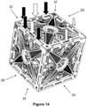
Figure 14 thefinal panel 2F is added to complete theattenuation crate 1. Again, thecentral tabs 4 are aligned with thecentral notches 18, and theprojections 15 inserted into theslots 14. For connection of thesixth panel 2F only a downward force need be applied to affix the sixth panel as indicated by the arrows. The is no requirement to slidetabs 17 intonotches 5 in this orientation. Since thesixth panel 2F is easier to fit, it is appreciated thatattenuation crates 1 may be assembled so that the sixth panel is the top panel in use, making assembly easier and enabling aninternal support 30 to be most easily introduced. - Once assembly of the six
panels attenuation crate 1 forms a cube creating a space or volume therebetween.Several attenuations crates 1 may be required to cover an area of ground, and therefore asmany attenuation crates 1 as required may be mounted alongside one another. - It is appreciated that the fifth and sixth panels may not fit together with the four already assembled wall panels without flexing of one or more of the panels during fitting to allow projections/slots, tabs/notches to align correctly making a very rigid structure. It is therefore important that a suitable plastic material grade is used to enable flexing during fitting.
-
Figure 15 shows an example of anattenuation crate 1 with aninternal support 30. Theinternal support 30 is a tube that is fitted to opposed panels in an interference condition to prevent accidental movement or displacement. - The
tube 30 has a number of 31 holes to permit passage of liquid. - The pictured
internal support 30 is formed from twoparts 32, 33 (seeFigure 16 ). The two parts are assembled together prior to fitting within the attenuation crate. - The two
parts - The pictured embodiment is formed from two
half cylinder sections lip 34 and a second edge with a series of C-shapedbrackets 35. In this way alip 34 of afirst part 32 is received by thebrackets 35 of asecond part 33; and alip 34 of thesecond part 33 is received by the C-shapedbrackets 35 of thefirst part 32; so as to interlock the twoparts - Ends of the
internal support 30 include acollar 39 that engages with theaperture 3A to locate and fix the internal support to the panel. -
Arrows 36 on an outer face of theinternal support 30 indicate the sliding direction of theparts internal support 30. - The C-shaped
brackets 35 each have ablock 38 that engages with adepression 37 provided on thelip 34 so that theparts blocks 38 anddepressions 37 are aligned and forced together so that theparts -
Figure 17 shows a partially assembledattenuation crate 1 with 5 assembledpanels 2. A first end of theinternal support 30 is received in acentral aperture 3A of thepanel 2. Thesupport 30 can be inserted vertically inside the crate at this stage (as shown inFigure 17 ). Alternatively theinternal support 30 can be inserted horizontally in the partially assembled crate by flexing two opposite side panels apart slightly to accept ends of theinternal support 30. -
Figure 18 shows a side view of theattenuation crate 1 with theinternal support 30. Theinternal support 30 has a collar 39 (seeFigure 19 ) concentric to thecentral aperture 3A on two opposed panels. -
Figure 19 shows a cross section of anattenuation crate 1 with aninternal support 30. - It is appreciated that the
internal support 30 can be arranged across any of the threeopposed panels 2. For example theinternal support 30 may be positioned where the greatest compressive forces are expected to be experienced. Due to the required steps of assembly to form acrate 1, by joining fourside panels 2 first and then adding top andbottom panels 2, where the internal support is vertical it can be positioned when five panels are connected and then engaged with the sixth panel as it is located. When theinternal support 30 is fitted horizontally with respect to the fifth and sixth panels the sides must be flexed to enable tocollar 39 to be received concentrically over the edges of thecentral apertures 3A of opposed side panels. It is appreciated that in some embodiments the collar may fit concentrically within thecentral aperture 3A. -
Figures 20 to 23 show one possible embodiment of attachment means 8 to releasably secure oneattenuation crate 1 to a neighbouringattenuation crate 1. The attachment means 8A, 8B, 8C,8D shown comprises two of theapertures 3B having walls 8A projecting outward that are received inapertures 3C of an adjoining panel.Apertures 3B have mesh partially closing the opening.Apertures 3C are open with no mesh. - The orientation of the attachment means 8 ensures that where
attenuation crates 1 are placed side by side, or one on top of another, thecircular walls 8A extending fromapertures 3B from theouter face 16 of one of thepanels 2 can be aligned with theapertures 3C on theouter face 16 of another one of thepanels 2, such that the attachment means 8 interlocks. -
Figure 20 shows twoattenuation crates 1 joined together through the attachment means 8 in a side by side configuration. - Each panel has a range of
different apertures central aperture 3A with an array of surroundingapertures mesh regions 3D to permit flow of liquid, such as rainwater (seeFigure 6 ). Themesh regions 3D also improves strength of thepanels 2. - In the pictured embodiments each
outer face 16 of apanel 2 has twoapertures 3B which include acircular wall 8A that projects from theouter face 16. Thewall 8A provides attachment means 8 for engagement with anaperture 3C of an adjacent panel. Thewalls 8A are received inapertures 3C. - The
wall 8A includes anode 8C on a resilientlydeformable arm 8D (seeFigures 21 ) that engages with arecess 8E of therim 8B ofaperture 3B (seeFigures 22 ) so thatadjacent panels 2 are joined together to form an array or attenuation crates. As thewall 8A is received in therim 8B ofaperture 3C the resilientlydeformable arm 8D is deformed to enable thenode 8C to pass through the rim to therecess 8E where thenode 8B is released to engage with therecess 8B, thereby preventing separate ofadjacent panels 2 without depression of thenode 8C to disengage if from therecess 8B (SeeFigures 22 and23 ). -
Figures 24A and 24B show a multi-wayinternal support 30 arranged in a partially assembledattenuation crate 1. Themulti-way support 30 has sixarms 40 that each have acollar end 39 that is received by acentral aperture 3A of apanel 2. - The
attenuation crate 1 has 5 panels assembled and theinternal support 30 is arranged to engage with all five fittedpanels 2.Collars 39 of theinternal support 30 are received in thecentral apertures 3A of eachpanel 2. - It is appreciated that to fit the internal support the ends of the internal supports are offset from the central apertures, for example by 45 degrees, so that one end is inserted to the central aperture of the lower panel. The
internal support 30 is then rotated to engage the four ends that extend in the same plane with thecentral apertures 3A of the fourside panels 2. -
- 1. Attenuation crate
- 2. Panel
- 3. Aperture
- 4. Tab
- 5. Notch
- 6. Alignment Indicia
- 7. Branding Indicia
- 8. Attachment means (8A wall, 8B rim, 8C node)
- 9. Corner tab
- 10. Corner notch
- 11. Part corner tab
- 12. Part corner notch
- 13. Side
- 14. Slot
- 15. Projection
- 16. Outer Face
- 17. Central tab
- 18. Central notch
- 19. Side
- 20. Cutaway regions
- 21. Inner face
- 30. Internal support
- 31. Holes
- 32. First part of internal support
- 33. Second part of internal support
- 34. Lip
- 35. C-shaped bracket
- 36. Arrows
- 37. Block
- 38. Depression
- 39. Collar
- 40. Arm
- The invention has been described by way of examples only and it will be appreciated that variation may be made to the above-mentioned embodiments without departing from the scope of protection as defined by the claims.
Claims (15)
- A panel (2) for forming an interlocking attenuation crate (1) comprising: a substantially square planar body with at least one aperture (3) to enable through passage of fluid; the panel has first and second adjacent sides (19) each having first interlocking features comprising at least one tab (4) and at least two notches (5); and third and fourth adjacent sides (13) with a second arrangement of interlocking features comprising at least two tabs (17) and at least one notch (18); characterised in that the tabs (4, 17) and notches (5, 18) of the first and second interlocking features are adapted to engage with each other and the at least one tab (4) of the first interlocking features is tapered and is adapted to be received by at least one corresponding notch (18) on the second interlocking features, the at least one notch is tapered to provide a mechanical interference fit to enable releasable connection of the panels (2) to form an attenuation crate (1) with six faces.
- A panel (2) according to claim 1 wherein the at least one tab (4) of the first interlocking features has a slot (14) and the at least one notch (18) of the second arrangement of interlocking features has a projection (15); and the slot (14) of the first interlocking feature receives the projection (15) of the second interlocking feature to enable releasable locking connection of panels (2) to form a six sided attenuation crate (1).
- A panel (2) according to a claim 1 or claim 2 wherein the first arrangement of interlocking features comprises a central tab (4) with a notch (5) on either side of said central tab (4).
- A panel (2) according to cany preceding claim wherein the second arrangement of interlocking features comprise a central notch (18) with a tab (17) on either side of said central notch (18).
- A panel (2) according to claim 3 and claim 4, wherein the central tab (4) incorporates the slot (14), and the central notch (18) incorporates the projection (15).
- A panel (2) according to any of the preceding claims, wherein each panel (2) has four corners (9, 10, 11,12) comprising a first full corner (9), a second notch corner (10) and third and fourth part corners (11, 12) that are shaped and dimensioned to engage and connect with corners (9, 10, 11, 12) of other panels.
- A panel (2) according to claim 6 wherein the full corner (9) and the corner notch (10) are in diagonally opposite corners, and wherein part corners (11, 12) are provided in the diagonally opposite corners.
- A panel (2) according to any of the preceding claims, whereby each panel (2) incorporates alignment indicia (6, 7) for orientating each panel (2) with respect to another panel (2) to form the crate (1) configuration.
- A panel (2) according to any of the preceding claims, wherein an outer face (16) of the panel (2) comprises attachment means (8A, 8B, 8C, 8D) for releasably securing to a corresponding attachment means (8A, 8B, 8C, 8D) in an outer face (16) of another panel (2), such that, in use, when six panels (2) are configured to form an attenuation crate (1), the outer face (16) of at least one of the panels (2) is releasably secured to a neighbouring attenuation crate (1).
- A panel (2) according to any preceding claim including an internal support (30).
- A panel (2) according to claim 10 wherein the internal support (30) is a tube.
- A panel (2) according to claim 10 or claim 11 wherein the internal support (30) is formed from two interlocking parts (32, 33).
- An attenuation crate (1) formed from six panels (2) according to claims 1 to 12 wherein sides (13, 19) of the panels (2) are adapted to releasably secured to each other to form a cube configuration defining an internal volume.
- An attenuation crate (1) according to claim 13, wherein a first side of a first panel comprises the first arrangement of interlocking features that are configured to interlock with a second side of a second panel provided with the second arrangement of interlocking features for aligning the panels to form a cube configuration.
- A method of assembling an attenuation crate (1) in a cube configuration from six panels (2) as claimed in any of claims 1 to 12, comprising the steps of: releasably securing four panels (2) together to form four sides (2A, 2B, 2C, 2D) of a cube configuration with four interlocking regions at which first interlocking features (19) of one panel engage with second interlocking features on (13) of the neighbouring panel to interlock at interlocking regions; whereby two of the four side panels (2A, 2B) are in a first orientation and the other two of the side panels (2C, 2D) are in a second orientation rotated through 90 degrees about their centre relative to the side panels in the first orientation; each panel (2) is releasably secured at right angles to said neighbouring panel (2) at the interlocking region; and mounting a further panel (2E, 2F) on either end of the four sides (2A, 2B, 2C, 2D) to form a top (2F) and a bottom (2E) of the cube configuration (1).
Priority Applications (1)
| Application Number | Priority Date | Filing Date | Title |
|---|---|---|---|
| EP22209939.2A EP4375436A1 (en) | 2022-11-28 | 2022-11-28 | A panel for forming attenuation crates |
Applications Claiming Priority (1)
| Application Number | Priority Date | Filing Date | Title |
|---|---|---|---|
| EP22209939.2A EP4375436A1 (en) | 2022-11-28 | 2022-11-28 | A panel for forming attenuation crates |
Publications (1)
| Publication Number | Publication Date |
|---|---|
| EP4375436A1 true EP4375436A1 (en) | 2024-05-29 |
Family
ID=84363864
Family Applications (1)
| Application Number | Title | Priority Date | Filing Date |
|---|---|---|---|
| EP22209939.2A Pending EP4375436A1 (en) | 2022-11-28 | 2022-11-28 | A panel for forming attenuation crates |
Country Status (1)
| Country | Link |
|---|---|
| EP (1) | EP4375436A1 (en) |
Citations (4)
| Publication number | Priority date | Publication date | Assignee | Title |
|---|---|---|---|---|
| JP2003034971A (en) * | 2001-07-23 | 2003-02-07 | Ebata Kk | Rainwater storage and infiltration tank |
| JP2003034970A (en) * | 2001-07-23 | 2003-02-07 | Ebata Kk | Rainwater storage/storage and infiltration tank |
| GB2444550A (en) | 2006-12-05 | 2008-06-11 | Source Control Systems Ltd | Modular storage and infiltration system for liquids |
| WO2010009410A1 (en) | 2008-07-17 | 2010-01-21 | Kreikemeier John E | Water retention/detention structure |
-
2022
- 2022-11-28 EP EP22209939.2A patent/EP4375436A1/en active Pending
Patent Citations (4)
| Publication number | Priority date | Publication date | Assignee | Title |
|---|---|---|---|---|
| JP2003034971A (en) * | 2001-07-23 | 2003-02-07 | Ebata Kk | Rainwater storage and infiltration tank |
| JP2003034970A (en) * | 2001-07-23 | 2003-02-07 | Ebata Kk | Rainwater storage/storage and infiltration tank |
| GB2444550A (en) | 2006-12-05 | 2008-06-11 | Source Control Systems Ltd | Modular storage and infiltration system for liquids |
| WO2010009410A1 (en) | 2008-07-17 | 2010-01-21 | Kreikemeier John E | Water retention/detention structure |
Similar Documents
| Publication | Publication Date | Title |
|---|---|---|
| US6736569B2 (en) | Structural modular interconnectable subsoil drainage cell | |
| US11634917B2 (en) | Structural cells, matrices and methods of assembly | |
| CA2776567C (en) | Drainage body | |
| CA2576600C (en) | Water drain tank or channel module | |
| EP2169127A1 (en) | Infiltration block | |
| US12286782B2 (en) | Stormwater management crate assembly with tapered columns | |
| US12049749B2 (en) | Module for drainage and method of assembly | |
| JP3208379B2 (en) | Filling material for rainwater storage and infiltration facilities | |
| US12305380B2 (en) | Stormwater management crate assembly with tapered columns and arched side panels | |
| EP4375436A1 (en) | A panel for forming attenuation crates | |
| GB2615175A (en) | A panel for forming attenuation crates | |
| US20230243143A1 (en) | Stormwater management crate assembly with tapered columns | |
| CA3228870A1 (en) | Chamber for subsoil fluid treatment | |
| JP7781603B2 (en) | Spatial building blocks, spatial building block connections, and storage spatial structures | |
| KR100901262B1 (en) | Artificial ground plant material box | |
| WO2024163592A1 (en) | Stormwater management crate assembly with tapered columns and side panels with column bearing components | |
| CN219909572U (en) | Multipurpose assembled component | |
| KR102337526B1 (en) | Grid panel type reinforced wall with filier and its construction method | |
| KR100591498B1 (en) | Stabilization Structure of the Filling Method for Site Construction in Apartment Complex | |
| CA2536011A1 (en) | Modular containment system | |
| EP2148016B1 (en) | Triple-dig unit | |
| CN119487271A (en) | Unit of a modular system for underground rainwater retention tanks, part for a modular system, underground rainwater retention tanks, method for constructing underground rainwater retention tanks, and use of a plurality of units for constructing underground rainwater retention tanks | |
| WO2024163596A1 (en) | Stormwater management crate assembly with tapered columns | |
| KR200261567Y1 (en) | Supporting wall of reinforced earth retaining wall | |
| HK1050922B (en) | Structural modular interconnectable subsoil drainage cell |
Legal Events
| Date | Code | Title | Description |
|---|---|---|---|
| PUAI | Public reference made under article 153(3) epc to a published international application that has entered the european phase |
Free format text: ORIGINAL CODE: 0009012 |
|
| STAA | Information on the status of an ep patent application or granted ep patent |
Free format text: STATUS: THE APPLICATION HAS BEEN PUBLISHED |
|
| AK | Designated contracting states |
Kind code of ref document: A1 Designated state(s): AL AT BE BG CH CY CZ DE DK EE ES FI FR GB GR HR HU IE IS IT LI LT LU LV MC ME MK MT NL NO PL PT RO RS SE SI SK SM TR |
|
| STAA | Information on the status of an ep patent application or granted ep patent |
Free format text: STATUS: REQUEST FOR EXAMINATION WAS MADE |
|
| 17P | Request for examination filed |
Effective date: 20240618 |
|
| RBV | Designated contracting states (corrected) |
Designated state(s): AL AT BE BG CH CY CZ DE DK EE ES FI FR GB GR HR HU IE IS IT LI LT LU LV MC ME MK MT NL NO PL PT RO RS SE SI SK SM TR |
|
| RIC1 | Information provided on ipc code assigned before grant |
Ipc: E03F 1/00 20060101AFI20260122BHEP |
|
| GRAP | Despatch of communication of intention to grant a patent |
Free format text: ORIGINAL CODE: EPIDOSNIGR1 |
|
| STAA | Information on the status of an ep patent application or granted ep patent |
Free format text: STATUS: GRANT OF PATENT IS INTENDED |
|
| INTG | Intention to grant announced |
Effective date: 20260226 |