EP4375418A1 - Hoisting accessory and method for transferring blower of pulp dryer from pulp dryer by means of hoisting accessory - Google Patents
Hoisting accessory and method for transferring blower of pulp dryer from pulp dryer by means of hoisting accessory Download PDFInfo
- Publication number
- EP4375418A1 EP4375418A1 EP23208974.8A EP23208974A EP4375418A1 EP 4375418 A1 EP4375418 A1 EP 4375418A1 EP 23208974 A EP23208974 A EP 23208974A EP 4375418 A1 EP4375418 A1 EP 4375418A1
- Authority
- EP
- European Patent Office
- Prior art keywords
- blower
- hoisting
- guideway
- hoisting accessory
- support
- Prior art date
- Legal status (The legal status is an assumption and is not a legal conclusion. Google has not performed a legal analysis and makes no representation as to the accuracy of the status listed.)
- Granted
Links
Images






Classifications
-
- D—TEXTILES; PAPER
- D21—PAPER-MAKING; PRODUCTION OF CELLULOSE
- D21F—PAPER-MAKING MACHINES; METHODS OF PRODUCING PAPER THEREON
- D21F5/00—Dryer section of machines for making continuous webs of paper
- D21F5/18—Drying webs by hot air
- D21F5/185—Supporting webs in hot air dryers
- D21F5/187—Supporting webs in hot air dryers by air jets
- D21F5/188—Blowing devices
-
- F—MECHANICAL ENGINEERING; LIGHTING; HEATING; WEAPONS; BLASTING
- F26—DRYING
- F26B—DRYING SOLID MATERIALS OR OBJECTS BY REMOVING LIQUID THEREFROM
- F26B21/00—Arrangements for supplying or controlling air or other gases for drying solid materials or objects
- F26B21/20—Circulating air or gases in closed cycles, e.g. wholly within the drying enclosure
-
- B—PERFORMING OPERATIONS; TRANSPORTING
- B66—HOISTING; LIFTING; HAULING
- B66C—CRANES; LOAD-ENGAGING ELEMENTS OR DEVICES FOR CRANES, CAPSTANS, WINCHES, OR TACKLES
- B66C1/00—Load-engaging elements or devices attached to lifting or lowering gear of cranes or adapted for connection therewith for transmitting lifting forces to articles or groups of articles
- B66C1/10—Load-engaging elements or devices attached to lifting or lowering gear of cranes or adapted for connection therewith for transmitting lifting forces to articles or groups of articles by mechanical means
-
- B—PERFORMING OPERATIONS; TRANSPORTING
- B66—HOISTING; LIFTING; HAULING
- B66C—CRANES; LOAD-ENGAGING ELEMENTS OR DEVICES FOR CRANES, CAPSTANS, WINCHES, OR TACKLES
- B66C1/00—Load-engaging elements or devices attached to lifting or lowering gear of cranes or adapted for connection therewith for transmitting lifting forces to articles or groups of articles
- B66C1/10—Load-engaging elements or devices attached to lifting or lowering gear of cranes or adapted for connection therewith for transmitting lifting forces to articles or groups of articles by mechanical means
- B66C1/42—Gripping members engaging only the external or internal surfaces of the articles
-
- B—PERFORMING OPERATIONS; TRANSPORTING
- B66—HOISTING; LIFTING; HAULING
- B66C—CRANES; LOAD-ENGAGING ELEMENTS OR DEVICES FOR CRANES, CAPSTANS, WINCHES, OR TACKLES
- B66C1/00—Load-engaging elements or devices attached to lifting or lowering gear of cranes or adapted for connection therewith for transmitting lifting forces to articles or groups of articles
- B66C1/10—Load-engaging elements or devices attached to lifting or lowering gear of cranes or adapted for connection therewith for transmitting lifting forces to articles or groups of articles by mechanical means
- B66C1/42—Gripping members engaging only the external or internal surfaces of the articles
- B66C1/44—Gripping members engaging only the external or internal surfaces of the articles and applying frictional forces
-
- B—PERFORMING OPERATIONS; TRANSPORTING
- B66—HOISTING; LIFTING; HAULING
- B66C—CRANES; LOAD-ENGAGING ELEMENTS OR DEVICES FOR CRANES, CAPSTANS, WINCHES, OR TACKLES
- B66C13/00—Other constructional features or details
- B66C13/04—Auxiliary devices for controlling movements of suspended loads, or preventing cable slack
- B66C13/08—Auxiliary devices for controlling movements of suspended loads, or preventing cable slack for depositing loads in desired attitudes or positions
-
- B—PERFORMING OPERATIONS; TRANSPORTING
- B66—HOISTING; LIFTING; HAULING
- B66D—CAPSTANS; WINCHES; TACKLES, e.g. PULLEY BLOCKS; HOISTS
- B66D3/00—Portable or mobile lifting or hauling appliances
-
- D—TEXTILES; PAPER
- D21—PAPER-MAKING; PRODUCTION OF CELLULOSE
- D21F—PAPER-MAKING MACHINES; METHODS OF PRODUCING PAPER THEREON
- D21F7/00—Other details of machines for making continuous webs of paper
-
- F—MECHANICAL ENGINEERING; LIGHTING; HEATING; WEAPONS; BLASTING
- F04—POSITIVE - DISPLACEMENT MACHINES FOR LIQUIDS; PUMPS FOR LIQUIDS OR ELASTIC FLUIDS
- F04D—NON-POSITIVE-DISPLACEMENT PUMPS
- F04D29/00—Details, component parts, or accessories
- F04D29/60—Mounting; Assembling; Disassembling
- F04D29/62—Mounting; Assembling; Disassembling of radial or helico-centrifugal pumps
- F04D29/624—Mounting; Assembling; Disassembling of radial or helico-centrifugal pumps especially adapted for elastic fluid pumps
- F04D29/626—Mounting or removal of fans
-
- F—MECHANICAL ENGINEERING; LIGHTING; HEATING; WEAPONS; BLASTING
- F26—DRYING
- F26B—DRYING SOLID MATERIALS OR OBJECTS BY REMOVING LIQUID THEREFROM
- F26B13/00—Machines and apparatus for drying fabrics, fibres, yarns, or other materials in long lengths, with progressive movement
- F26B13/10—Arrangements for feeding, heating or supporting materials; Controlling movement, tension or position of materials
- F26B13/101—Supporting materials without tension, e.g. on or between foraminous belts
- F26B13/104—Supporting materials without tension, e.g. on or between foraminous belts supported by fluid jets only; Fluid blowing arrangements for flotation dryers, e.g. coanda nozzles
Definitions
- the invention relates to a hoisting accessory for a blower of a pulp dryer, which hoisting accessory includes
- the invention also relates to a method for transferring a blower of a pulp dryer from the pulp dryer by means of the hoisting accessory.
- Pulp drying on the pulp dryer employs a large number of circulating air blowers.
- the circulating air blower of a pulp dryer consists of the blower section (impeller, body and motor) and guide vanes.
- the circulating air blowers are in blower towers one upon the other in the pulp dryer. If the impeller or motor of a circulating air blower - which is referred to as blower hereunder - needs to be changed, the blower section must be fully removed from the pulp dryer and guide vanes. The removal takes place by means of a hoisting accessory specifically made for this purpose, with the hoisting accessory fastened to an overhead crane, I-beam crane or mobile crane. The hoisting accessory must be fastened to the circulating air blower, which is why the hoisting accessory is brought into contact with the blower by means of a crane.
- the consequence of this is often that structures of the pulp dryer must be dismantled to make way for the hoisting accessory so that the hoisting accessory can be brought into contact with the blower.
- the hoisting accessory can be fastened to only a few circulating air blowers so that no service platforms, ducts, steam pipes or central vacuum cleaning system pipes need to be dismantled to make way for the hoisting accessory.
- a blower located close to the floor of the facility needs to be removed, all overhead service platforms, stairs and duct parts must be dismantled first for the replacement, and installed back into place later. This represents a very significant undertaking relative to the removal of the blower.
- the object of the present invention is to accomplish a hoisting accessory for a blower of a pulp dryer and a method for transferring a blower by means of the hoisting accessory, which enable an easier removal and transfer of a blower than prior art accessories and methods.
- the characteristic features of the invention with regard to the accessory will be more fully understood from claim 1 and with regard to the method from claim 13.
- the object of the hoisting accessory according to the present invention will be achieved by means of the hoisting accessory for a blower of a pulp dryer, which hoisting accessory includes a hoisting element for fastening the hoisting accessory to the blower to be hoisted, first fastening devices for locking the hoisting element to the blower for the duration of hoisting, a guideway comprising a first end and a second end as well as a carriage adapted on the guideway for transferring the blower on the guideway while said hoisting element is suspended from the carriage.
- the hoisting accessory includes a support device connected to the guideway for suspending the hoisting accessory from a second blower so that the guideway is supported essentially in the horizontal direction by means of the support device.
- the removal of a blower from a pulp dryer can be carried out in a much faster and easier manner than with prior art hoisting accessories, because the use of the hoisting accessory according to the invention requires much less dismantling of service platforms or other structures of the pulp dryer before removing a blower.
- This can be achieved by using in the transfer a guideway and a carriage movable on it, from which carriage the blower to be removed is suspended.
- the carriage it is possible to transfer the blower outwards from the pulp dryer past service platforms, whereby the final hoist can be carried out by means of an overhead crane or the winch of the hoisting accessory, for example.
- the hoisting accessory advantageously also includes a support element adapted to a first end of the guideway to support the guideway advantageously to another blower above.
- the hoisting accessory can be fastened to another blower from at least two points, which guarantees sturdy fastening.
- the hoisting accessory includes quick fastening devices, advantageously bolt fastenings, for fastening the hoisting element, support device and guideway to each other in a detachable manner.
- quick fastening devices advantageously bolt fastenings
- the hoisting accessory can be carried manually in parts to a service platform and assembled there prior to use.
- the hoisting accessory does not need to be hoisted by a crane, which would require the dismantling of service platforms and railings.
- the guideway advantageously includes a removable travel stop at one end.
- the travel stop is removable so that the carriage can be removed from the guideway for the duration of the transfer of the hoisting accessory.
- the purpose of the travel stop is to prevent the falling off of the carriage from the guideway when the blower is hoisted and transferred outside a service platform.
- the hoisting element advantageously includes a vertical arm comprising two ends, one end of which is connected to the carriage, and a hoisting support connected to the vertical arm and a second hoisting support connected to the other end of the vertical arm for fastening the hoisting element to the blower.
- the blower is connected to the carriage by means of the hoisting element.
- the second hoisting support forms a horizontal support for the blower, which is supported to the side of the blower by means of the hoisting support.
- the hoisting support is advantageously a hoisting beam. Applicable perforation may be formed in the hoisting beam for first fastening devices.
- a joint equipped with an axis of rotation that is perpendicular relative to the guideway, enabling the turning of the vertical arm around its longitudinal axis, at least partly.
- the blower attaches to the hoisting accessory from one of its edges, and the blower has length in the direction of the guideway. Because of this, if no joint was used, the guideway would have to continue much beyond the edge of a service platform to transfer a blower completely outside the service platform.
- the carriage can be transferred on the guideway past the service platform, and after this the vertical arm and the blower fastened to it by means of the support element can be turned 180 degrees relative to the vertical axis, whereby the entire length of the blower is transferred outside the service platform.
- the final hoist can be carried out by means of an overhead crane, for example.
- the hoisting accessory can include a winch attached in a detachable manner to one end of the guideway, by means of which winch the blower can be lowered on the floor with the hoisting support.
- the replacement work can be carried out completely without a separate overhead crane.
- the support device is advantageously adapted at an angle relative to the longitudinal direction of the guideway, and the support device is telescopic, comprising at least two parts that are at least partially inside each other in order to support the guideway in an essentially horizontal direction.
- the length of the support device can be adapted to be suitable also for the removal of blowers which are at a different distance from one another, so that the guideway is always essentially horizontal.
- the position of the guideway may differ a little relative to the horizontal, but the basic principle is that the carriage and blower could be transferred even by pushing by hand.
- the carriage can include an electric motor for driving the carriage to the guideway.
- the length of the carriage is advantageously 10-50 cm, advantageously 15-25 cm, so that the wheels advantageously included in the carriage are located at a sufficient distance from the joint that connects the vertical arm to the carriage.
- the centre of gravity of the blower is located at a distance from the fastening of the blower to the hoisting element, which tends to turn the blower and the hoisting element relative to the carriage.
- a sufficient length of the carriage is important so that the carriage does not exert a very point-like load on the guideway due to the torque caused by the blower, but instead, the load is distributed over a wider area of the guideway.
- At least the support device, and advantageously also the second support element include form-locked second fastening devices for fastening the support device, and advantageously also the second support element, around the edge belonging to the blower.
- the form-locked second fastening devices can be, for example, hook-shaped elements.
- the form-locked second fastening devices can be claw-like locking elements.
- the second fastening devices advantageously also include bolt fastenings for locking.
- the form-locked second fastening devices can be locked securely and reliably into contact with the blower in all directions of movement. This ensures the safety of the transfer.
- the hoisting element, support element and support device are advantageously of steel tube or steel profile.
- the parts of the hoisting accessory are of reasonably light weight as individual parts and can be lifted and transported by the user to the place of use.
- profile and tube structures are also sufficiently strong and rigid to withstand the transfer of a blower weighing less than a tonne.
- the length of the guideway is advantageously 0.5-1.0 m greater than the width of the service platforms.
- the length of the guideway can be 1.0-2.0 m, advantageously 1.3-1.7 m.
- the guideway is sufficiently long so that the carriage and the blower to be suspended from it can be transferred outside the service platforms.
- the support device can be fastened on the guideway at a point where the distance from the other end of the guideway is 0-30%, advantageously 5-15% of the length of the guideway.
- the support device accomplishes reliable support for the guideway, and the blower cannot move significantly on the guideway past the support point created by the support device for the guideway.
- the guideway advantageously consists of two adjacent and separate rails that are fastened to each other. This makes the structure of the guideway lighter.
- the purpose of the method according to the invention is achieved by means of a method for transferring a blower of a pulp dryer from the pulp dryer by means of a hoisting accessory, which method includes the following stages, where the railing of the pulp dryer service platform or a part of the service platform is removed, the hoisting accessory is brought up to the blower, the hoisting accessory is suspended advantageously from a second blower above, and a guideway belonging to the hoisting accessory is supported to the second blower essentially horizontally. Furthermore in the method, the hoisting accessory is fastened to the blower, the blower is removed from the pulp dryer and the blower is transferred horizontally by means of a carriage on the guideway out of the pulp dryer outside the service platform while the blower is suspended from the carriage.
- the hoisting accessory is advantageously brought as separate parts up to the blower, and before suspension, the hoisting accessory is assembled from the parts.
- an overhead crane for example, is not needed to hoist the hoisting accessory itself to the place of use, but the hoisting accessory can be transported by hand to the place of use and assembled ready for use.
- the blower is hoisted by means of the hoisting accessory after the hoisting accessory is fastened to the blower and removed from the pulp dryer, but before the blower is transferred on the guideway of the hoisting accessory.
- the blower is turned by means of the hoisting element 90°-270°, advantageously 160°-200° relative to the carriage around the joint when the carriage reaches one end of the guideway.
- the guideway can be a little shorter, when the structure of the blower can be turned around the joint to the other side, whereby the entire blower is outside the service platforms.
- the blower can be removed and replaced without a crane at any point of the pulp dryer. Moreover, the blower can be removed and replaced so that there is no need to dismantle service platforms, ducts, steam pipes, vacuum cleaner pipes, electric cables of the blower, or stairs.
- the replacement of the blower takes place significantly more quickly, in particular in those applications where there are many above-mentioned structures hampering the replacement work.
- occupational safety and user-friendliness are improved, and the blower can be maintained or replaced more easily.
- FIG 1 shows pulp dryer 100 depicted from a side.
- Pulp dryer 100 includes a great number, usually 100 to 300 blowers 12, which are fastened to blower towers 56, which are side by side.
- Individual blower tower 56 contains several blowers 12 one upon the other, with the blowers being essentially structurally similar. So that blowers 12 and pulp dryer 100 can be serviced in the first place, there are service platforms 52 on the sides of pulp dryer 100, which service platforms 52 prevent the hoisting of blower 12 directly out of pulp dryer 100 by means of an overhead crane.
- FIGs 2a-2c show one advantageous embodiment of hoisting accessory 10 according to the invention.
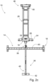
- Hoisting accessory 10 comprises the following basic parts to be fastened to each other in a detachable manner: hoisting element 14, first fastening devices 16 for fastening hoisting element 14 to blower 12 in accordance with Figures 3a and 3b , guideway 18 and carriage 24 adaptable on it as well as support element 26 and support device 28 for supporting guideway 18 to second blower 13, which is above blower 12 to be transferred, in accordance with Figures 3a and 3b .
- guideway 18 consists of two separate rails 78 ( Figure 5 ), but it is to be understood that the guideway may also be an individual elongated structure in the shape of the letter C opening downwards.
- Support device 28 is advantageously a support arm shown in the Figures, but alternatively a cable wire, chain, rope or similar can also be used as the support device.
- the above-mentioned parts are fastened to each other by means of quick fastening devices 30, which are advantageously bolt fasteners 32.
- the parts of the hoisting accessory are carried up to the blower to be transferred by using service platforms or pulled by means of, for example, a small cart which can be hoisted by an overhead crane onto a service platform at the edge area of the pulp dryer.
- the hoisting accessory is assembled ready for use in connection with a blower. So that the carrying could be carried out ergonomically, said parts are advantageously of steel tube or steel profile, in which case the maximum weight of an individual part is 20 kg. Tube or profile structures are rigid relative to their weight and hence applicable to their purpose of use.
- Hoisting element 14 advantageously includes vertical arm 36 in accordance with Figures 2a-2c , which vertical arm 36 is fastened by its first end 38 to carriage 24, and hoisting support 60 adapted in connection with first end 38 of vertical arm 36 and second hoisting support 62 adapted in connection with second end 40 of vertical arm 36 in order to fasten blower 12 to hoisting element 14.
- Hoisting support 60 is advantageously a hoisting beam, the width of which is advantageously 50-80% of the width of blower 12 and is an hollow or lightened steel tube or steel profile.
- the fastening of the hoisting beam to blower 12 takes place in accordance with Figure 3b through openings formed in blower 12 by using first fastening devices 16, which are advantageously bolt fastenings.
- blower 12 in terms of the openings endures the loading caused by the mass of the blower on it during hoisting
- flat bar irons or similar are advantageously used in the fastening on the back side, through which flat bar irons or similar the first fastening devices extend.
- the flat bar irons or similar distribute the loading over a larger area at the edges of the blower.
- second hoisting support 62 can be, for example, a steel profile that supports vertical support 36 against the blower and receives the loading that impacts eccentrically relative to the suspension point of hoisting support 14.
- the second hoisting support advantageously comprises support part 64 in the lateral direction of the blower and arm 66 that attaches to this transversely and that is equipped with threads.
- a counter thread can be adapted inside arm 66, and support part 64 connects to arm 66 by means of bolt 68.
- the distance of support part 64 relative to vertical arm 36 can be adjustable by turning bolt 68. By means of this adjustment, the position of a blower fastened to hoisting support 14 can be changed.
- Joint 42 equipped with an axle that is perpendicular relative to the guideway is advantageously formed between first end 38 of vertical arm 36 and carriage 24, which joint 42 enables the turning of hoisting support 14 relative to carriage 24.
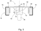
- Joint 42 is advantageously formed, in accordance with Figure 5 , by axle 70, to which vertical arm 36 attaches, and joint sleeve 72, inside which there are bearings for locking axle 70 to joint sleeve 72 and for enabling the mutual rotational movement between these.
- Joint sleeve 72 is advantageously welded by means of support triangles 74 to carriage 24, whereby the loads exerted on joint 42 are distributed evenly to the structures of carriage 24.
- Support device 28 by means of which guideway 18 and carriage 24 adapted on it are advantageously suspended from second blower 13 directly above blower 12 to be transferred in accordance with Figures 3a and 3b , is advantageously telescopic, consisting of two telescope parts 44 that are adapted partially inside each other.
- parts 44 can include series of holes, through which a locking pin is adapted after the correct dimension of the support device has been found. The correct dimension is determined by the position of the guideway, which must be essentially horizontal.
- Support device 28 is advantageously fastened to upper edge 47 of second blower 13 directly above blower 12 to be hoisted, in accordance with Figures 3a and 3b .
- Support element 26 is fastened to first end 20 of guideway 18, which support element 26 can be a support beam, which is supported against the blower, advantageously to bottom edge 49 of second blower 13 above blower 12 to be hoisted, in accordance with Figure 3b .
- the support element can alternatively be fastened, if necessary, for example from the side of the blower or by means of rods also suspended from the upper edge of the blower.
- Both support device 28 and support element 26 advantageously include form-locked second fastening devices 46, where the form locking can be carried out by means of claw-like arms 73 that extend around the edge of the blower, advantageously around the upper or bottom edge 47, 49.
- form-locked second fastening devices 46 also include locking bolts 76, which press the edge of 47, 49 of second blower 13 tightly against second fastening devices 46.
- Travel stop 34 shown in Figure 2a is advantageously fastened in a detachable manner to second end 22 of guideway 18.
- One purpose of travel stop 34 is to prevent carriage 24 placed on guideway 18 from falling off from guideway 18, but on the other hand it also enables the installation of the carriage on the guideway from the end of guideway 18 in connection with the assembly of the hoisting accessory.
- a further purpose of the travel stop is to combine two rails 78 shown in Figure 5 , which belong advantageously to guideway 18 and which are at a distance from each other, into guideways 18 at their one end 22. At the first end of guideway 18, support element 26 fulfils the same function.
- guideway 18 includes, in addition to ends 20 and 22 of guideway 18, advantageously also at least one intermediate support 80, which ties parallel rails 78 to a constant distance from each other.
- intermediate support 80 can be a so-called c-clamp retaining plate.
- Rails 78 advantageously have a cross-sectional shape of so-called C-rails in accordance with Figure 5 , where wheels 82 advantageously included in carriage 24 are inside the C-shape of rail 78, where they can only move in the longitudinal direction of guideway 18, with the C-shape preventing lateral movement. In this way, carriage 24 effectively transmits the forces exerted on it by the mass of the blower via wheels 82 to guideway 18 and via it further to support device 28 and support element 26 and further to second blower 13 above.
- Carriage 24 includes body 84, to which wheels 82 are advantageously fastened to the corners, and said joint 42 attaches between these.
- Axle 70 of joint 42 advantageously includes an adjustment option, by means of which, by rotating axle 70, vertical arm 36 can be adjusted 5-100 mm, advantageously 20-40 mm in the vertical direction.
- the axle can include adjustment bolt 81 that goes through body 84 of carriage 24.
- Body 84 of carriage 24 can also include support iron 83, which is adapted on top of body 84 to strengthen body 84.
- the length of the guideway of the lifting accessory according to the invention can be 1.0-2.0 m, advantageously 1.3-1.8 m, and the height of the entire lifting accessory from the second fastening devices of support device 28 to the bottom end of the vertical arm of the hoisting element is 2-4 m, advantageously 2.5-3.5 m.
- the width of the hoisting support can be 1-2 m, advantageously 1.4-1.7 m.
- the length of the carriage in the longitudinal direction of the guideway can be 10-50 cm, advantageously 20-30 cm.
- the material used in the hoisting accessory can be, for example, materials in accordance with standards EN 10025-2 or EN 10149-2, with a yield strength of Re/Rp0.2 of the level 300-800 Mpa, tensile strength Rm 400-1000 Mpa and elongation at break A 10-25%.
- the hoisting accessory can advantageously be made lighter by means of lightening openings, as, for example, vertical support 36 has been made lighter in Figure 3b .
- a corresponding lightening can also be in the second support element and in the hoisting support.
- the weight of the blower to be hoisted is generally less than 1000 kg, while the weight of the hoisting accessory can be less than 200 kg.
- FIG. 6 shows stages of the method according to the invention as a block diagram in one embodiment.
- the hoisting accessory is advantageously installed on a blower located above the blower to be replaced or, in the case of the topmost blower, on a wall section.
- a covering strip and insulation must advantageously be removed from between blowers so that the top and bottom edge of the blower can be exposed and be used by the second fastening devices.
- the guideway and support device are fastened to the lugs in the blower above by means of ball lock pins that advantageously form the second fastening devices, and tightened with the bolts of the bolt fastenings against the wall of the blower above, as shown in Figure 3a .
- the support device is locked to the guideway, and the long fastening hole advantageously belonging to it enables the adjustment of the guideway to a horizontal position before tightening.
- the support device is adjusted to the longer position of its telescopic parts and can be locked with two pins delivered with the hoisting accessory.
- stage 204 the carriage is adapted on the guideway by turning the travel stop away to give way to the carriage so that the carriage and intermediate support can be adapted on the guideway.
- stage 206 the travel stop is tightened back into place for the duration of the replacement, using bolts, for example.
- the hoisting element is fastened to holes on the sides of the blower to be replaced, by using, for example, bolts and fastening plates delivered with the support element belonging to the hoisting element.
- the blower can be fastened by the upper holes in the end plate belonging to the support element, but in other cases by the lower holes in the end plate.
- the support element can be fastened to the vertical arm of the hoisting element by means of a ball lock pin.
- the vertical location of the hoisting element can be adjusted by the bolt above the carriage.
- the bolt in the second support element of the vertical arm can be used for adjusting the position of the blower.
- the blower to be removed can be removed for hoisting from the part of the blower that remains in the pulp dryer.
- blower 12 to be replaced can be removed from the pulp dryer to the suspension of the replacement device in accordance with stages 212-218 and by making reference to Figures 4a-4c .
- the screw above carriage 24 is used for adjusting the height of the hoisting element, in other words vertical location, and blower 12 is suspended from hoisting accessory 10. If necessary, the position of blower 12 is adjusted in stage 214 by adjusting second hoisting support 62 by a screw.
- blower 12 suspended from hoisting accessory 10 is transferred by means of carriage 24 from the position in accordance with Figure 4a from first end 20 of guideway 18 to second end 22 in accordance with Figures 4a and 4b .
- blower 12 is turned 180° around joint 42 of hoisting element 14 to the reach of an overhead crane in accordance with Figure 4c .
- the centre of gravity of the blower is attached to the overhead crane, after which the hoisting accessory can be detached from the blower in stage 224.
- the carriage can include a separate hoisting lug, by which the blower to be removed can be attached to the overhead crane.
- a new blower can be installed by repeating stages 200-224 in reverse order.
- blower to be removed is the topmost blower in a blower tower, it is possible to form separate hoisting counter plates in the blower tower for the use of the hoisting accessory, with the counter plates used for supporting the hoisting accessory.
- blower instead of a second blower directly above the blower to be removed, it can be thought that there are two support devices, which support the hoisting accessory to blowers located on the sides of the blower or to blowers located diagonally relative to the blower.
Landscapes
- Engineering & Computer Science (AREA)
- Mechanical Engineering (AREA)
- General Engineering & Computer Science (AREA)
- Textile Engineering (AREA)
- Structures Of Non-Positive Displacement Pumps (AREA)
- Load-Engaging Elements For Cranes (AREA)
Abstract
- a hoisting element (14) for fastening the hoisting accessory (10) to the blower (12) to be hoisted, and
- first fastening devices (16) for locking the hoisting element (14) to the blower (12) for the duration of hoisting,
- a guideway (18) comprising a first end (20) and second end (22),
- a carriage (24) adapted on the guideway (18) for transferring a blower (12) on the guideway (18) while said hoisting element (14) is suspended from said carriage (24),
- a support device (28) connected to said guideway (18) for suspending the hoisting accessory (10) from a second blower (13) so that said guideway (18) is supported essentially in the horizontal direction by means of the support device (28).
Description
- The invention relates to a hoisting accessory for a blower of a pulp dryer, which hoisting accessory includes
- a hoisting element for fastening the hoisting accessory to the blower to be hoisted, and
- first fastening devices for locking the hoisting element to the blower for the duration of hoisting.
- The invention also relates to a method for transferring a blower of a pulp dryer from the pulp dryer by means of the hoisting accessory.
- Pulp drying on the pulp dryer employs a large number of circulating air blowers. The circulating air blower of a pulp dryer consists of the blower section (impeller, body and motor) and guide vanes. The circulating air blowers are in blower towers one upon the other in the pulp dryer. If the impeller or motor of a circulating air blower - which is referred to as blower hereunder - needs to be changed, the blower section must be fully removed from the pulp dryer and guide vanes. The removal takes place by means of a hoisting accessory specifically made for this purpose, with the hoisting accessory fastened to an overhead crane, I-beam crane or mobile crane. The hoisting accessory must be fastened to the circulating air blower, which is why the hoisting accessory is brought into contact with the blower by means of a crane.
- In practice, the consequence of this is often that structures of the pulp dryer must be dismantled to make way for the hoisting accessory so that the hoisting accessory can be brought into contact with the blower. Especially on the drive side, the hoisting accessory can be fastened to only a few circulating air blowers so that no service platforms, ducts, steam pipes or central vacuum cleaning system pipes need to be dismantled to make way for the hoisting accessory. As an example, if a blower located close to the floor of the facility needs to be removed, all overhead service platforms, stairs and duct parts must be dismantled first for the replacement, and installed back into place later. This represents a very significant undertaking relative to the removal of the blower.
- On the other hand, a pulp dryer is often placed so that there is not much space available on its sides, which further complicates the removal of the blower.
- The object of the present invention is to accomplish a hoisting accessory for a blower of a pulp dryer and a method for transferring a blower by means of the hoisting accessory, which enable an easier removal and transfer of a blower than prior art accessories and methods. The characteristic features of the invention with regard to the accessory will be more fully understood from claim 1 and with regard to the method from
claim 13. - The object of the hoisting accessory according to the present invention will be achieved by means of the hoisting accessory for a blower of a pulp dryer, which hoisting accessory includes a hoisting element for fastening the hoisting accessory to the blower to be hoisted, first fastening devices for locking the hoisting element to the blower for the duration of hoisting, a guideway comprising a first end and a second end as well as a carriage adapted on the guideway for transferring the blower on the guideway while said hoisting element is suspended from the carriage. Moreover, the hoisting accessory includes a support device connected to the guideway for suspending the hoisting accessory from a second blower so that the guideway is supported essentially in the horizontal direction by means of the support device.
- When referring to the removal of a blower in this context, what is meant is the removal of the blower section of a circulating air blower from the guide vanes, which remain in place in the pulp dryer.
- By means of the hoisting accessory according to the present invention, the removal of a blower from a pulp dryer can be carried out in a much faster and easier manner than with prior art hoisting accessories, because the use of the hoisting accessory according to the invention requires much less dismantling of service platforms or other structures of the pulp dryer before removing a blower. This can be achieved by using in the transfer a guideway and a carriage movable on it, from which carriage the blower to be removed is suspended. By means of the carriage, it is possible to transfer the blower outwards from the pulp dryer past service platforms, whereby the final hoist can be carried out by means of an overhead crane or the winch of the hoisting accessory, for example.
- The hoisting accessory advantageously also includes a support element adapted to a first end of the guideway to support the guideway advantageously to another blower above. By means of the support element, the hoisting accessory can be fastened to another blower from at least two points, which guarantees sturdy fastening.
- According to one embodiment, the hoisting accessory includes quick fastening devices, advantageously bolt fastenings, for fastening the hoisting element, support device and guideway to each other in a detachable manner. In this way, the hoisting accessory can be carried manually in parts to a service platform and assembled there prior to use. In this case, the hoisting accessory does not need to be hoisted by a crane, which would require the dismantling of service platforms and railings.
- The guideway advantageously includes a removable travel stop at one end. The travel stop is removable so that the carriage can be removed from the guideway for the duration of the transfer of the hoisting accessory. The purpose of the travel stop is to prevent the falling off of the carriage from the guideway when the blower is hoisted and transferred outside a service platform.
- The hoisting element advantageously includes a vertical arm comprising two ends, one end of which is connected to the carriage, and a hoisting support connected to the vertical arm and a second hoisting support connected to the other end of the vertical arm for fastening the hoisting element to the blower. In this way, the blower is connected to the carriage by means of the hoisting element. In a hoisting situation, the second hoisting support forms a horizontal support for the blower, which is supported to the side of the blower by means of the hoisting support.
- The hoisting support is advantageously a hoisting beam. Applicable perforation may be formed in the hoisting beam for first fastening devices.
- Between the carriage and vertical arm, there is advantageously a joint equipped with an axis of rotation that is perpendicular relative to the guideway, enabling the turning of the vertical arm around its longitudinal axis, at least partly. By means of the joint, it is possible to reduce the length required of the guideway for transferring a blower outside a service platform. The blower attaches to the hoisting accessory from one of its edges, and the blower has length in the direction of the guideway. Because of this, if no joint was used, the guideway would have to continue much beyond the edge of a service platform to transfer a blower completely outside the service platform. By means of the joint, the carriage can be transferred on the guideway past the service platform, and after this the vertical arm and the blower fastened to it by means of the support element can be turned 180 degrees relative to the vertical axis, whereby the entire length of the blower is transferred outside the service platform. Outside the service platform, the final hoist can be carried out by means of an overhead crane, for example.
- According to one embodiment, the hoisting accessory can include a winch attached in a detachable manner to one end of the guideway, by means of which winch the blower can be lowered on the floor with the hoisting support. In this case, the replacement work can be carried out completely without a separate overhead crane.
- The support device is advantageously adapted at an angle relative to the longitudinal direction of the guideway, and the support device is telescopic, comprising at least two parts that are at least partially inside each other in order to support the guideway in an essentially horizontal direction. By means of the telescopic support device, the length of the support device can be adapted to be suitable also for the removal of blowers which are at a different distance from one another, so that the guideway is always essentially horizontal. The position of the guideway may differ a little relative to the horizontal, but the basic principle is that the carriage and blower could be transferred even by pushing by hand.
- Alternatively, the carriage can include an electric motor for driving the carriage to the guideway.
- The length of the carriage is advantageously 10-50 cm, advantageously 15-25 cm, so that the wheels advantageously included in the carriage are located at a sufficient distance from the joint that connects the vertical arm to the carriage. The centre of gravity of the blower is located at a distance from the fastening of the blower to the hoisting element, which tends to turn the blower and the hoisting element relative to the carriage. A sufficient length of the carriage is important so that the carriage does not exert a very point-like load on the guideway due to the torque caused by the blower, but instead, the load is distributed over a wider area of the guideway.
- According to one embodiment, at least the support device, and advantageously also the second support element, include form-locked second fastening devices for fastening the support device, and advantageously also the second support element, around the edge belonging to the blower. By means of the form-locked second fastening devices, the fastening of the support device and advantageously also of the second support element to a blower directly above the blower to be hoisted takes place quickly and reliably. The form-locked second fastening devices can be, for example, hook-shaped elements.
- The form-locked second fastening devices can be claw-like locking elements.
- The second fastening devices advantageously also include bolt fastenings for locking. By means of the bolt fastenings, the form-locked second fastening devices can be locked securely and reliably into contact with the blower in all directions of movement. This ensures the safety of the transfer.
- The hoisting element, support element and support device are advantageously of steel tube or steel profile. In this way, the parts of the hoisting accessory are of reasonably light weight as individual parts and can be lifted and transported by the user to the place of use. On the other hand, profile and tube structures are also sufficiently strong and rigid to withstand the transfer of a blower weighing less than a tonne.
- The length of the guideway is advantageously 0.5-1.0 m greater than the width of the service platforms. According to an embodiment, the length of the guideway can be 1.0-2.0 m, advantageously 1.3-1.7 m. In this case, the guideway is sufficiently long so that the carriage and the blower to be suspended from it can be transferred outside the service platforms.
- The support device can be fastened on the guideway at a point where the distance from the other end of the guideway is 0-30%, advantageously 5-15% of the length of the guideway. In this case, the support device accomplishes reliable support for the guideway, and the blower cannot move significantly on the guideway past the support point created by the support device for the guideway.
- The guideway advantageously consists of two adjacent and separate rails that are fastened to each other. This makes the structure of the guideway lighter.
- The purpose of the method according to the invention is achieved by means of a method for transferring a blower of a pulp dryer from the pulp dryer by means of a hoisting accessory, which method includes the following stages, where the railing of the pulp dryer service platform or a part of the service platform is removed, the hoisting accessory is brought up to the blower, the hoisting accessory is suspended advantageously from a second blower above, and a guideway belonging to the hoisting accessory is supported to the second blower essentially horizontally. Furthermore in the method, the hoisting accessory is fastened to the blower, the blower is removed from the pulp dryer and the blower is transferred horizontally by means of a carriage on the guideway out of the pulp dryer outside the service platform while the blower is suspended from the carriage.
- In the method according to the invention, only one upper part of the service platform is removed instead of all overhead structures, when the blower can be transferred outside the service platform by means of the carriage and guideway of the hoisting accessory to lower it down or lift it up. In this way, the transfer can be carried out quickly and effortlessly. This is particularly important, because the number of blowers in a pulp dryer can be between 100 and 300.
- The hoisting accessory is advantageously brought as separate parts up to the blower, and before suspension, the hoisting accessory is assembled from the parts. In this way, an overhead crane, for example, is not needed to hoist the hoisting accessory itself to the place of use, but the hoisting accessory can be transported by hand to the place of use and assembled ready for use.
- According to one embodiment, the blower is hoisted by means of the hoisting accessory after the hoisting accessory is fastened to the blower and removed from the pulp dryer, but before the blower is transferred on the guideway of the hoisting accessory.
- According to one embodiment, the blower is turned by means of the hoisting element 90°-270°, advantageously 160°-200° relative to the carriage around the joint when the carriage reaches one end of the guideway. In this way, the guideway can be a little shorter, when the structure of the blower can be turned around the joint to the other side, whereby the entire blower is outside the service platforms.
- With the hoisting accessory and method according to the invention, the blower can be removed and replaced without a crane at any point of the pulp dryer. Moreover, the blower can be removed and replaced so that there is no need to dismantle service platforms, ducts, steam pipes, vacuum cleaner pipes, electric cables of the blower, or stairs. The replacement of the blower takes place significantly more quickly, in particular in those applications where there are many above-mentioned structures hampering the replacement work. As a result of the above-mentioned advantages, occupational safety and user-friendliness are improved, and the blower can be maintained or replaced more easily.
- The invention, which is not restricted to the embodiments presented below, is described in more detail by making reference to the enclosed drawings, in which:
- Figure 1
- shows a pulp dryer in an axonometric view depicted from a side,
- Figure 2a
- shows the hoisting accessory according to the invention in an axonometric view depicted separately,
- Figure 2b
- shows the hoisting accessory according to the invention depicted from a side,
- Figure 2c
- shows the hoisting accessory according to the invention depicted from the front,
- Figure 3a
- shows the fastening of the hoisting accessory according to the invention to the blower, depicted from a side,
- Figure 3b
- shows the fastening of the hoisting accessory according to the invention to the blower, depicted in an axonometric view,
- Figure 4a-4c
- show the stages of transferring the blower, depicted from a side,
- Figure 5
- shows the cross-section of the guideway and carriage,
- Figure 6
- shows the stages of the method according to the invention as a block diagram.
- The figures refer to different parts of the invention using the following reference numbers:
- 10
- hoisting accessory
- 12
- blower
- 13
- second blower
- 14
- hoisting element
- 16
- first fastening devices
- 18
- guideway
- 20
- first end
- 22
- second end
- 24
- carriage
- 26
- support element
- 28
- support device
- 30
- quick fastening devices
- 32
- bolt fasteners
- 34
- travel stop
- 36
- vertical arm
- 38
- first end of vertical arm
- 40
- second end of vertical arm
- 42
- joint
- 44
- part of telescope
- 46
- second fastening devices
- 47
- top edge
- 49
- bottom edge
- 50
- bolt fastenings
- 52
- service platform
- 54
- service platform railing
- 56
- blower tower
- 60
- hoisting support
- 62
- second hoisting support
- 64
- support part
- 66
- arm
- 68
- bolt
- 70
- shaft
- 72
- joint sleeve
- 73
- claw-like arms
- 74
- support triangle
- 76
- locking bolts
- 78
- rail
- 80
- intermediate support
- 81
- adjustment bolt
- 82
- wheels
- 83
- support iron
- 84
- carriage body.
-
Figure 1 showspulp dryer 100 depicted from a side.Pulp dryer 100 includes a great number, usually 100 to 300blowers 12, which are fastened to blower towers 56, which are side by side.Individual blower tower 56 containsseveral blowers 12 one upon the other, with the blowers being essentially structurally similar. So thatblowers 12 andpulp dryer 100 can be serviced in the first place, there areservice platforms 52 on the sides ofpulp dryer 100, whichservice platforms 52 prevent the hoisting ofblower 12 directly out ofpulp dryer 100 by means of an overhead crane. -
Figures 2a-2c show one advantageous embodiment of hoistingaccessory 10 according to the invention. Hoistingaccessory 10 comprises the following basic parts to be fastened to each other in a detachable manner: hoistingelement 14,first fastening devices 16 for fastening hoistingelement 14 toblower 12 in accordance withFigures 3a and3b ,guideway 18 andcarriage 24 adaptable on it as well assupport element 26 andsupport device 28 for supportingguideway 18 tosecond blower 13, which is aboveblower 12 to be transferred, in accordance withFigures 3a and3b . In the embodiments ofFigures 2a-5 ,guideway 18 consists of two separate rails 78 (Figure 5 ), but it is to be understood that the guideway may also be an individual elongated structure in the shape of the letter C opening downwards.Support device 28 is advantageously a support arm shown in the Figures, but alternatively a cable wire, chain, rope or similar can also be used as the support device. - The above-mentioned parts are fastened to each other by means of
quick fastening devices 30, which areadvantageously bolt fasteners 32. In practice, the parts of the hoisting accessory are carried up to the blower to be transferred by using service platforms or pulled by means of, for example, a small cart which can be hoisted by an overhead crane onto a service platform at the edge area of the pulp dryer. The hoisting accessory is assembled ready for use in connection with a blower. So that the carrying could be carried out ergonomically, said parts are advantageously of steel tube or steel profile, in which case the maximum weight of an individual part is 20 kg. Tube or profile structures are rigid relative to their weight and hence applicable to their purpose of use. - Hoisting
element 14 advantageously includesvertical arm 36 in accordance withFigures 2a-2c , whichvertical arm 36 is fastened by itsfirst end 38 tocarriage 24, and hoistingsupport 60 adapted in connection withfirst end 38 ofvertical arm 36 and second hoistingsupport 62 adapted in connection withsecond end 40 ofvertical arm 36 in order to fastenblower 12 to hoistingelement 14. Hoistingsupport 60 is advantageously a hoisting beam, the width of which is advantageously 50-80% of the width ofblower 12 and is an hollow or lightened steel tube or steel profile. The fastening of the hoisting beam toblower 12 takes place in accordance withFigure 3b through openings formed inblower 12 by usingfirst fastening devices 16, which are advantageously bolt fastenings. So that the structure ofblower 12 in terms of the openings endures the loading caused by the mass of the blower on it during hoisting, flat bar irons or similar are advantageously used in the fastening on the back side, through which flat bar irons or similar the first fastening devices extend. The flat bar irons or similar distribute the loading over a larger area at the edges of the blower. - In accordance with
Figure 3b , second hoistingsupport 62 can be, for example, a steel profile that supportsvertical support 36 against the blower and receives the loading that impacts eccentrically relative to the suspension point of hoistingsupport 14. The second hoisting support advantageously comprisessupport part 64 in the lateral direction of the blower andarm 66 that attaches to this transversely and that is equipped with threads. A counter thread can be adapted insidearm 66, and supportpart 64 connects to arm 66 by means ofbolt 68. In this way, the distance ofsupport part 64 relative tovertical arm 36 can be adjustable by turningbolt 68. By means of this adjustment, the position of a blower fastened to hoistingsupport 14 can be changed. - Joint 42 equipped with an axle that is perpendicular relative to the guideway is advantageously formed between
first end 38 ofvertical arm 36 andcarriage 24, which joint 42 enables the turning of hoistingsupport 14 relative tocarriage 24. Joint 42 is advantageously formed, in accordance withFigure 5 , byaxle 70, to whichvertical arm 36 attaches, andjoint sleeve 72, inside which there are bearings for lockingaxle 70 tojoint sleeve 72 and for enabling the mutual rotational movement between these.Joint sleeve 72 is advantageously welded by means ofsupport triangles 74 tocarriage 24, whereby the loads exerted on joint 42 are distributed evenly to the structures ofcarriage 24. -
Support device 28, by means of which guideway 18 andcarriage 24 adapted on it are advantageously suspended fromsecond blower 13 directly aboveblower 12 to be transferred in accordance withFigures 3a and3b , is advantageously telescopic, consisting of twotelescope parts 44 that are adapted partially inside each other. In order to lock the parts to each other in the operation position,parts 44 can include series of holes, through which a locking pin is adapted after the correct dimension of the support device has been found. The correct dimension is determined by the position of the guideway, which must be essentially horizontal.Support device 28 is advantageously fastened toupper edge 47 ofsecond blower 13 directly aboveblower 12 to be hoisted, in accordance withFigures 3a and3b . -
Support element 26 is fastened tofirst end 20 ofguideway 18, which supportelement 26 can be a support beam, which is supported against the blower, advantageously tobottom edge 49 ofsecond blower 13 aboveblower 12 to be hoisted, in accordance withFigure 3b . The support element can alternatively be fastened, if necessary, for example from the side of the blower or by means of rods also suspended from the upper edge of the blower. Bothsupport device 28 andsupport element 26 advantageously include form-lockedsecond fastening devices 46, where the form locking can be carried out by means of claw-like arms 73 that extend around the edge of the blower, advantageously around the upper orbottom edge second fastening devices 46 also include lockingbolts 76, which press the edge of 47, 49 ofsecond blower 13 tightly againstsecond fastening devices 46. -
Travel stop 34 shown inFigure 2a is advantageously fastened in a detachable manner tosecond end 22 ofguideway 18. One purpose oftravel stop 34 is to preventcarriage 24 placed onguideway 18 from falling off fromguideway 18, but on the other hand it also enables the installation of the carriage on the guideway from the end ofguideway 18 in connection with the assembly of the hoisting accessory. A further purpose of the travel stop is to combine tworails 78 shown inFigure 5 , which belong advantageously to guideway 18 and which are at a distance from each other, intoguideways 18 at their oneend 22. At the first end ofguideway 18,support element 26 fulfils the same function. In this embodiment,guideway 18 includes, in addition to ends 20 and 22 ofguideway 18, advantageously also at least oneintermediate support 80, which tiesparallel rails 78 to a constant distance from each other. In accordance withFigure 2a , there are advantageously at least twointermediate supports 80. The intermediate support can be a so-called c-clamp retaining plate. -
Rails 78 advantageously have a cross-sectional shape of so-called C-rails in accordance withFigure 5 , wherewheels 82 advantageously included incarriage 24 are inside the C-shape ofrail 78, where they can only move in the longitudinal direction ofguideway 18, with the C-shape preventing lateral movement. In this way,carriage 24 effectively transmits the forces exerted on it by the mass of the blower viawheels 82 toguideway 18 and via it further to supportdevice 28 andsupport element 26 and further tosecond blower 13 above. -
Carriage 24 includesbody 84, to whichwheels 82 are advantageously fastened to the corners, and said joint 42 attaches between these.Axle 70 of joint 42 advantageously includes an adjustment option, by means of which, by rotatingaxle 70,vertical arm 36 can be adjusted 5-100 mm, advantageously 20-40 mm in the vertical direction. For rotation, the axle can includeadjustment bolt 81 that goes throughbody 84 ofcarriage 24.Body 84 ofcarriage 24 can also includesupport iron 83, which is adapted on top ofbody 84 to strengthenbody 84. - The length of the guideway of the lifting accessory according to the invention can be 1.0-2.0 m, advantageously 1.3-1.8 m, and the height of the entire lifting accessory from the second fastening devices of
support device 28 to the bottom end of the vertical arm of the hoisting element is 2-4 m, advantageously 2.5-3.5 m. The width of the hoisting support can be 1-2 m, advantageously 1.4-1.7 m. The length of the carriage in the longitudinal direction of the guideway can be 10-50 cm, advantageously 20-30 cm. The material used in the hoisting accessory can be, for example, materials in accordance with standards EN 10025-2 or EN 10149-2, with a yield strength of Re/Rp0.2 of the level 300-800 Mpa, tensile strength Rm 400-1000 Mpa and elongation at break A 10-25%. The hoisting accessory can advantageously be made lighter by means of lightening openings, as, for example,vertical support 36 has been made lighter inFigure 3b . A corresponding lightening can also be in the second support element and in the hoisting support. The weight of the blower to be hoisted is generally less than 1000 kg, while the weight of the hoisting accessory can be less than 200 kg. -
Figure 6 shows stages of the method according to the invention as a block diagram in one embodiment. The hoisting accessory is advantageously installed on a blower located above the blower to be replaced or, in the case of the topmost blower, on a wall section. For the removal of the blower, a covering strip and insulation must advantageously be removed from between blowers so that the top and bottom edge of the blower can be exposed and be used by the second fastening devices. Instage 200, the guideway and support device are fastened to the lugs in the blower above by means of ball lock pins that advantageously form the second fastening devices, and tightened with the bolts of the bolt fastenings against the wall of the blower above, as shown inFigure 3a . Instage 202, the support device is locked to the guideway, and the long fastening hole advantageously belonging to it enables the adjustment of the guideway to a horizontal position before tightening. When fastened to a wall section, the support device is adjusted to the longer position of its telescopic parts and can be locked with two pins delivered with the hoisting accessory. - In
stage 204, the carriage is adapted on the guideway by turning the travel stop away to give way to the carriage so that the carriage and intermediate support can be adapted on the guideway. Instage 206, the travel stop is tightened back into place for the duration of the replacement, using bolts, for example. - In
stage 206, the hoisting element is fastened to holes on the sides of the blower to be replaced, by using, for example, bolts and fastening plates delivered with the support element belonging to the hoisting element. When replacing the topmost blower, the blower can be fastened by the upper holes in the end plate belonging to the support element, but in other cases by the lower holes in the end plate. Instage 208, the support element can be fastened to the vertical arm of the hoisting element by means of a ball lock pin. - In
stage 210, the vertical location of the hoisting element can be adjusted by the bolt above the carriage. The bolt in the second support element of the vertical arm can be used for adjusting the position of the blower. - When the hoisting accessory is fastened firmly to the blower to be removed and supported to an overhead blower, the blower to be removed can be removed for hoisting from the part of the blower that remains in the pulp dryer.
- When the hoisting accessory and hoisting element are fastened to the blower to be transferred in accordance with stages 200-210,
blower 12 to be replaced can be removed from the pulp dryer to the suspension of the replacement device in accordance with stages 212-218 and by making reference toFigures 4a-4c . Instage 212, the screw abovecarriage 24 is used for adjusting the height of the hoisting element, in other words vertical location, andblower 12 is suspended from hoistingaccessory 10. If necessary, the position ofblower 12 is adjusted instage 214 by adjustingsecond hoisting support 62 by a screw. Instage 216,blower 12 suspended from hoistingaccessory 10 is transferred by means ofcarriage 24 from the position in accordance withFigure 4a fromfirst end 20 ofguideway 18 tosecond end 22 in accordance withFigures 4a and 4b . Instage 220,blower 12 is turned 180° around joint 42 of hoistingelement 14 to the reach of an overhead crane in accordance withFigure 4c . Instage 222, the centre of gravity of the blower is attached to the overhead crane, after which the hoisting accessory can be detached from the blower instage 224. The carriage can include a separate hoisting lug, by which the blower to be removed can be attached to the overhead crane. A new blower can be installed by repeating stages 200-224 in reverse order. - If the blower to be removed is the topmost blower in a blower tower, it is possible to form separate hoisting counter plates in the blower tower for the use of the hoisting accessory, with the counter plates used for supporting the hoisting accessory.
- Alternatively, instead of a second blower directly above the blower to be removed, it can be thought that there are two support devices, which support the hoisting accessory to blowers located on the sides of the blower or to blowers located diagonally relative to the blower.
Claims (15)
- A hoisting accessory (10) for a blower (12) of a pulp dryer (100), which hoisting accessory (10) includes:- a hoisting element (14) for fastening the hoisting accessory (10) to the blower (12) to be hoisted, and- first fastening devices (16) for locking the hoisting element (14) to the blower (12) for the duration of hoisting,
characterised in that the hoisting accessory (10) also includes- a guideway (18) comprising a first end (20) and second end (22),- a carriage (24) adapted on the guideway (18) for transferring a blower (12) on the guideway (18) while said hoisting element (14) is suspended from said carriage (24),- a support device (28) connected to said guideway (18) for suspending the hoisting accessory (10) from a second blower (13) so that said guideway (18) is supported essentially in the horizontal direction by means of the support device (28). - The hoisting accessory according to claim 1, characterised in that the hoisting accessory (10) also includes a support element (26) adapted to a first end (20) of the guideway (18) to support the guideway (18) advantageously to another blower (13) above.
- The hoisting accessory according to claim 1 or 2, characterised in that the hoisting accessory (10) includes quick fastening devices (30), advantageously bolt fastenings (32), for fastening said hoisting element (14), support device (28) and guideway (18) to each other in a detachable manner.
- The hoisting accessory according to any one of the claims 1-3, characterised in that said guideway (18) includes a removable travel stop (34) at one end (22).
- The hoisting accessory according to any one of the claims 1-4, characterised in that the hoisting element (14) includes- a vertical arm (36) comprising two ends (38, 40), one end (38) of which is connected to the carriage (24),- a hoisting support (60) connected to the vertical arm (36) for fastening the hoisting element (14) to the blower (12), and- a second hoisting support (62) connected to a second end (40) of the vertical arm (36) for fastening the hoisting element (14) to the blower (12).
- The hoisting accessory according to claim 5, characterised in that between said carriage (24) and vertical arm (36), there is a joint (42) equipped with an axis of rotation that is perpendicular relative to the guideway (18), enabling the turning of the vertical arm (36) around its longitudinal axis, at least partly.
- The hoisting accessory according to any one of the claims 1-6, characterised in that said support device (28) is adapted at an angle relative to the longitudinal direction of the guideway (18), and the support device (28) is telescopic, comprising at least two parts (44) that are at least partially adapted inside each other in order to support said guideway (18) in an essentially horizontal direction.
- The hoisting accessory according to any one of the claims 2-7, characterised in that at least the support device (28), and advantageously also the support element (26), include form-locked second fastening devices (46) for fastening the support device (28), and advantageously also the support element (26), around the edge (47, 49) belonging to a second blower (13).
- The hoisting accessory according to claim 8, characterised in that the second fastening devices (46) also include bolt fastenings (50) for locking.
- The hoisting accessory according to any one of the claims 2-9, characterised in that said hoisting element (14), support element (26) and support device (28) are of steel pipe or steel profile.
- The hoisting accessory according to any one of the claims 1-10, characterised in that said support device (28) is fastened on the guideway (18) at a point where the distance from the other end (22) of the guideway (18) is 0-30%, advantageously 5-15% of the length of the guideway (18).
- The hoisting accessory according to any one of the claims 1-11, characterised in that the guideway (18) consists of two adjacent and separate rails (78) that are fastened to each other.
- A method for transferring a blower (12) of a pulp dryer (100) from the pulp dryer (100) by means of a hoisting accessory (10), which method includes the following stages:a) a railing (54) of the pulp dryer (100) service platform (52) or a part of the service platform (52) is removed,b) the hoisting accessory (10) is brought up to the blower (12),c) the hoisting accessory (10) is fastened to the blower (12),d) the blower (12) is removed from the pulp dryer (100),e) the blower (12) is transferred in an essentially horizontal position out of the pulp dryer (100) while the blower (12) is suspended from the hoisting accessory (10),characterised in that prior to stage c)- the hoisting accessory (10) is suspended advantageously from a second blower (13) directly above the blower (12),- the guideway (18) belonging to the hoisting accessory (10) is supported to the second blower (13) essentially horizontally,and in stage e) the blower (12) is transferred by means of the carriage (24) on the guideway (18) in order to transfer the blower (12) horizontally outside the service platform (52).
- The method according to claim 13, characterised in that in stage b) the hoisting accessory (10) is brought as separate parts up to the blower (12), and before suspension, the hoisting accessory (10) is assembled from the parts.
- The method according to claim 13 or 14, characterised in that the blower (12) is hoisted by means of the hoisting accessory (10) after stage d) before stage e).
Applications Claiming Priority (1)
| Application Number | Priority Date | Filing Date | Title |
|---|---|---|---|
| FI20226038A FI130575B (en) | 2022-11-22 | 2022-11-22 | Lifting aid device and method for moving a pulp dryer fan using a lifting aid device |
Publications (2)
| Publication Number | Publication Date |
|---|---|
| EP4375418A1 true EP4375418A1 (en) | 2024-05-29 |
| EP4375418B1 EP4375418B1 (en) | 2025-04-02 |
Family
ID=88778282
Family Applications (1)
| Application Number | Title | Priority Date | Filing Date |
|---|---|---|---|
| EP23208974.8A Active EP4375418B1 (en) | 2022-11-22 | 2023-11-10 | Hoisting accessory and method for transferring blower of pulp dryer from pulp dryer by means of hoisting accessory |
Country Status (3)
| Country | Link |
|---|---|
| EP (1) | EP4375418B1 (en) |
| CN (1) | CN118062710A (en) |
| FI (1) | FI130575B (en) |
Citations (3)
| Publication number | Priority date | Publication date | Assignee | Title |
|---|---|---|---|---|
| WO1999028550A1 (en) * | 1997-11-17 | 1999-06-10 | Valmet Corporation | Method and device for changing an endless felt |
| WO2000061863A1 (en) * | 1999-04-13 | 2000-10-19 | Metso Paper, Inc. | Apparatus for cleaning the drying air of a pulp dryer |
| CN106181885B (en) * | 2016-09-09 | 2017-05-31 | 安徽山鹰纸业股份有限公司 | A kind of steady paper bellows attaching/detaching apparatus of paper machine cadre |
-
2022
- 2022-11-22 FI FI20226038A patent/FI130575B/en active IP Right Grant
-
2023
- 2023-11-10 EP EP23208974.8A patent/EP4375418B1/en active Active
- 2023-11-22 CN CN202311567244.3A patent/CN118062710A/en active Pending
Patent Citations (3)
| Publication number | Priority date | Publication date | Assignee | Title |
|---|---|---|---|---|
| WO1999028550A1 (en) * | 1997-11-17 | 1999-06-10 | Valmet Corporation | Method and device for changing an endless felt |
| WO2000061863A1 (en) * | 1999-04-13 | 2000-10-19 | Metso Paper, Inc. | Apparatus for cleaning the drying air of a pulp dryer |
| CN106181885B (en) * | 2016-09-09 | 2017-05-31 | 安徽山鹰纸业股份有限公司 | A kind of steady paper bellows attaching/detaching apparatus of paper machine cadre |
Also Published As
| Publication number | Publication date |
|---|---|
| FI130575B (en) | 2023-11-22 |
| EP4375418B1 (en) | 2025-04-02 |
| FI20226038A1 (en) | 2023-11-22 |
| CN118062710A (en) | 2024-05-24 |
Similar Documents
| Publication | Publication Date | Title |
|---|---|---|
| CA2544881C (en) | Method and device for installation of guide rails in a lift shaft | |
| KR101823342B1 (en) | Construction apparatus of supporting post | |
| EP4375418B1 (en) | Hoisting accessory and method for transferring blower of pulp dryer from pulp dryer by means of hoisting accessory | |
| CN115367617B (en) | Device and method for replacing trolley track for ship unloader | |
| US5086880A (en) | Elevator traveling cable grip | |
| CN114590727B (en) | Device and method for suspending pipes in confined space | |
| CN114873445A (en) | Bridge prefabricated part hoisting tool and hoisting method | |
| US4441849A (en) | Apparatus for hoisting loads to elevated building locations | |
| CN215592366U (en) | Indoor hoisting equipment | |
| CN215711265U (en) | Temporary support hoisting device utilizing existing support under bridge | |
| JP2008214062A (en) | Lifting device and structural material mounting method | |
| CN213923658U (en) | Conveying device for lifting materials in super high-rise building floor | |
| CN113187250A (en) | Pull-out channel structure of suspension unloading platform | |
| CN113479762A (en) | Indoor hoisting equipment | |
| JP2011252318A (en) | Load receiving platform and its transferring method | |
| JP4054800B2 (en) | Climbing scaffold | |
| CN220078360U (en) | Concrete prefabricated section transfer device | |
| EP4414310A1 (en) | Elevator traction machine installation apparatus and elevator traction machine installation method | |
| EP4112527A1 (en) | Method of mounting an elevator drive | |
| CN213923834U (en) | Small-space multifunctional detachable loading and unloading device | |
| CN216377189U (en) | Hoisting and transporting trolley | |
| CN112320574A (en) | Municipal works construction lifts by crane transport anchor clamps | |
| CN219548349U (en) | Attached climbing unloading platform device | |
| CN223483601U (en) | Hoisting tool for pipeline installation | |
| CN217437493U (en) | Skid-mounted frame and skid-mounted integrated system |
Legal Events
| Date | Code | Title | Description |
|---|---|---|---|
| PUAI | Public reference made under article 153(3) epc to a published international application that has entered the european phase |
Free format text: ORIGINAL CODE: 0009012 |
|
| STAA | Information on the status of an ep patent application or granted ep patent |
Free format text: STATUS: THE APPLICATION HAS BEEN PUBLISHED |
|
| AK | Designated contracting states |
Kind code of ref document: A1 Designated state(s): AL AT BE BG CH CY CZ DE DK EE ES FI FR GB GR HR HU IE IS IT LI LT LU LV MC ME MK MT NL NO PL PT RO RS SE SI SK SM TR |
|
| STAA | Information on the status of an ep patent application or granted ep patent |
Free format text: STATUS: REQUEST FOR EXAMINATION WAS MADE |
|
| 17P | Request for examination filed |
Effective date: 20240619 |
|
| RBV | Designated contracting states (corrected) |
Designated state(s): AL AT BE BG CH CY CZ DE DK EE ES FI FR GB GR HR HU IE IS IT LI LT LU LV MC ME MK MT NL NO PL PT RO RS SE SI SK SM TR |
|
| GRAP | Despatch of communication of intention to grant a patent |
Free format text: ORIGINAL CODE: EPIDOSNIGR1 |
|
| STAA | Information on the status of an ep patent application or granted ep patent |
Free format text: STATUS: GRANT OF PATENT IS INTENDED |
|
| INTG | Intention to grant announced |
Effective date: 20241212 |
|
| GRAS | Grant fee paid |
Free format text: ORIGINAL CODE: EPIDOSNIGR3 |
|
| GRAA | (expected) grant |
Free format text: ORIGINAL CODE: 0009210 |
|
| STAA | Information on the status of an ep patent application or granted ep patent |
Free format text: STATUS: THE PATENT HAS BEEN GRANTED |
|
| AK | Designated contracting states |
Kind code of ref document: B1 Designated state(s): AL AT BE BG CH CY CZ DE DK EE ES FI FR GB GR HR HU IE IS IT LI LT LU LV MC ME MK MT NL NO PL PT RO RS SE SI SK SM TR |
|
| REG | Reference to a national code |
Ref country code: GB Ref legal event code: FG4D |
|
| RIN1 | Information on inventor provided before grant (corrected) |
Inventor name: SIMILAE, ESKO Inventor name: KYLAENIEMI, TOMMI |
|
| REG | Reference to a national code |
Ref country code: CH Ref legal event code: EP |
|
| REG | Reference to a national code |
Ref country code: DE Ref legal event code: R096 Ref document number: 602023002724 Country of ref document: DE |
|
| REG | Reference to a national code |
Ref country code: IE Ref legal event code: FG4D |
|
| REG | Reference to a national code |
Ref country code: SE Ref legal event code: TRGR |
|
| REG | Reference to a national code |
Ref country code: NL Ref legal event code: MP Effective date: 20250402 |
|
| PG25 | Lapsed in a contracting state [announced via postgrant information from national office to epo] |
Ref country code: NL Free format text: LAPSE BECAUSE OF FAILURE TO SUBMIT A TRANSLATION OF THE DESCRIPTION OR TO PAY THE FEE WITHIN THE PRESCRIBED TIME-LIMIT Effective date: 20250402 |
|
| PG25 | Lapsed in a contracting state [announced via postgrant information from national office to epo] |
Ref country code: PT Free format text: LAPSE BECAUSE OF FAILURE TO SUBMIT A TRANSLATION OF THE DESCRIPTION OR TO PAY THE FEE WITHIN THE PRESCRIBED TIME-LIMIT Effective date: 20250804 Ref country code: FI Free format text: LAPSE BECAUSE OF FAILURE TO SUBMIT A TRANSLATION OF THE DESCRIPTION OR TO PAY THE FEE WITHIN THE PRESCRIBED TIME-LIMIT Effective date: 20250402 Ref country code: ES Free format text: LAPSE BECAUSE OF FAILURE TO SUBMIT A TRANSLATION OF THE DESCRIPTION OR TO PAY THE FEE WITHIN THE PRESCRIBED TIME-LIMIT Effective date: 20250402 |
|
| REG | Reference to a national code |
Ref country code: LT Ref legal event code: MG9D |
|
| PG25 | Lapsed in a contracting state [announced via postgrant information from national office to epo] |
Ref country code: NO Free format text: LAPSE BECAUSE OF FAILURE TO SUBMIT A TRANSLATION OF THE DESCRIPTION OR TO PAY THE FEE WITHIN THE PRESCRIBED TIME-LIMIT Effective date: 20250702 Ref country code: GR Free format text: LAPSE BECAUSE OF FAILURE TO SUBMIT A TRANSLATION OF THE DESCRIPTION OR TO PAY THE FEE WITHIN THE PRESCRIBED TIME-LIMIT Effective date: 20250703 |
|
| PG25 | Lapsed in a contracting state [announced via postgrant information from national office to epo] |
Ref country code: PL Free format text: LAPSE BECAUSE OF FAILURE TO SUBMIT A TRANSLATION OF THE DESCRIPTION OR TO PAY THE FEE WITHIN THE PRESCRIBED TIME-LIMIT Effective date: 20250402 |
|
| PG25 | Lapsed in a contracting state [announced via postgrant information from national office to epo] |
Ref country code: BG Free format text: LAPSE BECAUSE OF FAILURE TO SUBMIT A TRANSLATION OF THE DESCRIPTION OR TO PAY THE FEE WITHIN THE PRESCRIBED TIME-LIMIT Effective date: 20250402 |
|
| PG25 | Lapsed in a contracting state [announced via postgrant information from national office to epo] |
Ref country code: HR Free format text: LAPSE BECAUSE OF FAILURE TO SUBMIT A TRANSLATION OF THE DESCRIPTION OR TO PAY THE FEE WITHIN THE PRESCRIBED TIME-LIMIT Effective date: 20250402 |
|
| PG25 | Lapsed in a contracting state [announced via postgrant information from national office to epo] |
Ref country code: RS Free format text: LAPSE BECAUSE OF FAILURE TO SUBMIT A TRANSLATION OF THE DESCRIPTION OR TO PAY THE FEE WITHIN THE PRESCRIBED TIME-LIMIT Effective date: 20250702 |
|
| PG25 | Lapsed in a contracting state [announced via postgrant information from national office to epo] |
Ref country code: IS Free format text: LAPSE BECAUSE OF FAILURE TO SUBMIT A TRANSLATION OF THE DESCRIPTION OR TO PAY THE FEE WITHIN THE PRESCRIBED TIME-LIMIT Effective date: 20250802 |
|
| PG25 | Lapsed in a contracting state [announced via postgrant information from national office to epo] |
Ref country code: LV Free format text: LAPSE BECAUSE OF FAILURE TO SUBMIT A TRANSLATION OF THE DESCRIPTION OR TO PAY THE FEE WITHIN THE PRESCRIBED TIME-LIMIT Effective date: 20250402 |
|
| REG | Reference to a national code |
Ref country code: DE Ref legal event code: R097 Ref document number: 602023002724 Country of ref document: DE |
|
| PG25 | Lapsed in a contracting state [announced via postgrant information from national office to epo] |
Ref country code: DK Free format text: LAPSE BECAUSE OF FAILURE TO SUBMIT A TRANSLATION OF THE DESCRIPTION OR TO PAY THE FEE WITHIN THE PRESCRIBED TIME-LIMIT Effective date: 20250402 Ref country code: SM Free format text: LAPSE BECAUSE OF FAILURE TO SUBMIT A TRANSLATION OF THE DESCRIPTION OR TO PAY THE FEE WITHIN THE PRESCRIBED TIME-LIMIT Effective date: 20250402 |
|
| PGFP | Annual fee paid to national office [announced via postgrant information from national office to epo] |
Ref country code: AT Payment date: 20260113 Year of fee payment: 3 |
|
| PGFP | Annual fee paid to national office [announced via postgrant information from national office to epo] |
Ref country code: SE Payment date: 20251119 Year of fee payment: 3 |
|
| PG25 | Lapsed in a contracting state [announced via postgrant information from national office to epo] |
Ref country code: CZ Free format text: LAPSE BECAUSE OF FAILURE TO SUBMIT A TRANSLATION OF THE DESCRIPTION OR TO PAY THE FEE WITHIN THE PRESCRIBED TIME-LIMIT Effective date: 20250402 |
|
| PG25 | Lapsed in a contracting state [announced via postgrant information from national office to epo] |
Ref country code: EE Free format text: LAPSE BECAUSE OF FAILURE TO SUBMIT A TRANSLATION OF THE DESCRIPTION OR TO PAY THE FEE WITHIN THE PRESCRIBED TIME-LIMIT Effective date: 20250402 |
|
| PG25 | Lapsed in a contracting state [announced via postgrant information from national office to epo] |
Ref country code: SK Free format text: LAPSE BECAUSE OF FAILURE TO SUBMIT A TRANSLATION OF THE DESCRIPTION OR TO PAY THE FEE WITHIN THE PRESCRIBED TIME-LIMIT Effective date: 20250402 |
|
| PG25 | Lapsed in a contracting state [announced via postgrant information from national office to epo] |
Ref country code: IT Free format text: LAPSE BECAUSE OF FAILURE TO SUBMIT A TRANSLATION OF THE DESCRIPTION OR TO PAY THE FEE WITHIN THE PRESCRIBED TIME-LIMIT Effective date: 20250402 |
|
| PLBE | No opposition filed within time limit |
Free format text: ORIGINAL CODE: 0009261 |
|
| STAA | Information on the status of an ep patent application or granted ep patent |
Free format text: STATUS: NO OPPOSITION FILED WITHIN TIME LIMIT |
|
| REG | Reference to a national code |
Ref country code: CH Ref legal event code: L10 Free format text: ST27 STATUS EVENT CODE: U-0-0-L10-L00 (AS PROVIDED BY THE NATIONAL OFFICE) Effective date: 20260211 |
|
| PG25 | Lapsed in a contracting state [announced via postgrant information from national office to epo] |
Ref country code: RO Free format text: LAPSE BECAUSE OF FAILURE TO SUBMIT A TRANSLATION OF THE DESCRIPTION OR TO PAY THE FEE WITHIN THE PRESCRIBED TIME-LIMIT Effective date: 20250402 |
|
| 26N | No opposition filed |
Effective date: 20260105 |