EP4375194A1 - Système de propulsion d'un aéronef comportant une nacelle asymétrique - Google Patents
Système de propulsion d'un aéronef comportant une nacelle asymétrique Download PDFInfo
- Publication number
- EP4375194A1 EP4375194A1 EP23211881.0A EP23211881A EP4375194A1 EP 4375194 A1 EP4375194 A1 EP 4375194A1 EP 23211881 A EP23211881 A EP 23211881A EP 4375194 A1 EP4375194 A1 EP 4375194A1
- Authority
- EP
- European Patent Office
- Prior art keywords
- nacelle
- covers
- propulsion system
- axis
- cover
- Prior art date
- Legal status (The legal status is an assumption and is not a legal conclusion. Google has not performed a legal analysis and makes no representation as to the accuracy of the status listed.)
- Granted
Links
Images


Classifications
-
- B—PERFORMING OPERATIONS; TRANSPORTING
- B64—AIRCRAFT; AVIATION; COSMONAUTICS
- B64D—EQUIPMENT FOR FITTING IN OR TO AIRCRAFT; FLIGHT SUITS; PARACHUTES; ARRANGEMENT OR MOUNTING OF POWER PLANTS OR PROPULSION TRANSMISSIONS IN AIRCRAFT
- B64D29/00—Power-plant nacelles, fairings or cowlings
- B64D29/02—Power-plant nacelles, fairings or cowlings associated with wings
-
- B—PERFORMING OPERATIONS; TRANSPORTING
- B64—AIRCRAFT; AVIATION; COSMONAUTICS
- B64D—EQUIPMENT FOR FITTING IN OR TO AIRCRAFT; FLIGHT SUITS; PARACHUTES; ARRANGEMENT OR MOUNTING OF POWER PLANTS OR PROPULSION TRANSMISSIONS IN AIRCRAFT
- B64D29/00—Power-plant nacelles, fairings or cowlings
- B64D29/08—Inspection panels for power plants
-
- B—PERFORMING OPERATIONS; TRANSPORTING
- B64—AIRCRAFT; AVIATION; COSMONAUTICS
- B64D—EQUIPMENT FOR FITTING IN OR TO AIRCRAFT; FLIGHT SUITS; PARACHUTES; ARRANGEMENT OR MOUNTING OF POWER PLANTS OR PROPULSION TRANSMISSIONS IN AIRCRAFT
- B64D27/00—Arrangement or mounting of power plants in aircraft; Aircraft characterised by the type or position of power plants
- B64D27/02—Aircraft characterised by the type or position of power plants
- B64D27/10—Aircraft characterised by the type or position of power plants of gas-turbine type
- B64D27/12—Aircraft characterised by the type or position of power plants of gas-turbine type within, or attached to, wings
-
- B—PERFORMING OPERATIONS; TRANSPORTING
- B64—AIRCRAFT; AVIATION; COSMONAUTICS
- B64D—EQUIPMENT FOR FITTING IN OR TO AIRCRAFT; FLIGHT SUITS; PARACHUTES; ARRANGEMENT OR MOUNTING OF POWER PLANTS OR PROPULSION TRANSMISSIONS IN AIRCRAFT
- B64D29/00—Power-plant nacelles, fairings or cowlings
-
- B—PERFORMING OPERATIONS; TRANSPORTING
- B64—AIRCRAFT; AVIATION; COSMONAUTICS
- B64D—EQUIPMENT FOR FITTING IN OR TO AIRCRAFT; FLIGHT SUITS; PARACHUTES; ARRANGEMENT OR MOUNTING OF POWER PLANTS OR PROPULSION TRANSMISSIONS IN AIRCRAFT
- B64D29/00—Power-plant nacelles, fairings or cowlings
- B64D29/06—Attaching of nacelles, fairings or cowlings
Definitions
- the present invention relates to an aircraft propulsion system comprising an asymmetrical nacelle for a turbomachine.
- the present invention also relates to an aircraft comprising at least one such propulsion system.
- Fig. 4 is a front view of a propulsion system 400 of the state of the art for an aircraft.
- the aircraft comprises a fuselage on either side of which is fixed a wing 402.
- the propulsion system 400 conventionally comprises a mast 404, a turbomachine having a core 408 and a nacelle 410.
- Fig. 4 shows the port side of an aircraft where the wing 402 has a proximal end 402a secured to the fuselage of the aircraft and a distal end 402b.
- the lower surface 402c of the wing 402 rises between the proximal end 402a and the distal end 402b.
- the mast 404 is fixed under the wing and it carries the core 408 and the nacelle 410.
- the nacelle 410 has covers which are movable between a closed position in which the covers are tightened around the core 408 and an open position in which the covers are separated from the core 408.
- the nacelle 410 has two interior covers 412a-b (also called IFS for “Internal Fixed Structure” in Anglo-Saxon terminology) and two exterior covers 414a-b (also called OS for “Outer Structure” in Anglo-Saxon terminology). ).
- Each cover 412a-b, 414a-b generally takes the shape of a half-cylinder and the nacelle 410 has, on either side of a vertical midplane XZ and passing through the central axis of the core 408, a inner cover 412a-b and an outer cover 414a-b around the inner cover 412a-b.
- the two interior covers 412a-b are joined at the level of the middle plane and generally form a cylinder which surrounds the core 408 and constitutes the internal part of a secondary vein 411
- the two exterior covers 414a-b are joined at the level of the middle plane and generally form a cylinder which surrounds the interior covers 412a-b and constitutes the external part of the secondary vein 411.
- Each outer cover 414a-b is mounted articulated on the mast 404 via hinges whose axes 415a-b are generally parallel to the longitudinal axis of the turbomachine.
- Each inner cover 412a-b is fixed to the associated outer cover 414a-b and the fixing is ensured by lower structural elements 416a-b and upper structural elements 418a-b.
- the associated inner cover 412a-b is fixed to the outer cover 414a-b in the lower part at 6 o'clock by a lower structural element 416a-b and in the upper part at 12 o'clock by a structural element superior 418a-b.
- the two axes 415a-b of the hinges are symmetrical to each other with respect to the middle plane XZ and the lower structural elements 416a-b are joined at the level of the middle plane XZ.
- the opening of the covers, and in particular here the port side cover 414a is limited due to the proximity of the wing 402 and it is therefore necessary to find a particular arrangement which allows a larger opening and therefore better accessibility during maintenance operations.
- the document FR-A-3 053 957 discloses a state-of-the-art propulsion system.
- An object of the present invention is to provide a propulsion system which comprises an asymmetrical nacelle.
- the two exterior covers and the lower structural elements are joined at the level of the separation plane.
- the two exterior covers and the lower structural elements are joined at the level of the separation plane.
- the invention also proposes an aircraft comprising a wing under which at least one propulsion system according to one of the preceding variants is fixed via its mast.
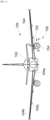
- FIG. 1 shows an aircraft 100 which comprises a fuselage 102 and a wing 104 on each side of the fuselage 102. Under each wing 104, the aircraft 100 has a propulsion system 150 which comprises a mast 152, a turbomachine and a nacelle 154.
- the turbomachine which includes a core is housed inside the nacelle 154.
- the longitudinal axis X is the central axis of the core.
- Each wing 104 has a proximal end 104a secured to the fuselage 102 and a distal end 104b. Conventionally, the lower surface 104c of the wing 104 rises between the proximal end 104a and the distal end 104b. The wing 104 therefore has positive dihedral.
- the mast 152 is fixed under the lower surface 104c of the wing 104 and the mast 152 carries the core and the nacelle 154.
- Fig. 2 shows the propulsion system 150 in the closed position and the Fig. 3 shows the propulsion system 150 in the open position.
- the 150 propulsion system of Figs. 2 And 3 is that for which the mast 152 is fixed on a port side on the aircraft 100.
- the nacelle 154 has covers which are movable between the closed position in which the covers are tightened around the core 208 and an open position in which the covers are spaced away from the core 208.
- the nacelle 154 has two interior covers 212a-b (also called IFS for “Internal Fixed Structure” in Anglo-Saxon terminology) and two external covers 214a-b (also called OS for “Outer Structure” in Anglo-Saxon terminology).
- the two inner covers 212a-b are arranged around the core 208 and the two outer covers 214a-b are arranged around the inner covers 212a-b.
- the propulsion system 150 has a vertical middle plane P (XZ) passing through the longitudinal axis X and a separation plane P' which contains the longitudinal axis ⁇ acute and counted positively clockwise in front view.
- the angle ⁇ is for example between 5° and 20°, and more particularly of the order of 10°.
- the propulsion system 150 For a propulsion system 150 whose mast 152 is fixed on a starboard side of the aircraft 100, the propulsion system 150 has a vertical midplane P (XZ) passing through the longitudinal axis separation plane P' which contains the longitudinal axis
- the angle ⁇ is for example between 5° and 20°, and more particularly of the order of 10°.
- Each cover 212a-b, 214a-b generally takes the shape of a portion of a cylinder and the nacelle 154 has, on either side of the separation plane P', an interior cover 212a-b and an exterior cover 214a- b around the inner cover 212a-b.
- Each cover 212a-b, 214a-b is coaxial with the longitudinal axis X.
- the two exterior covers 214a-b are joined at the level of the separation plane P'.
- the two exterior covers 214a-b are joined at the level of the separation plane P', which makes it possible to shift the locks which are arranged at the level of the separation plane P' by shifting them to move them away from the ground.
- this embodiment allows better accessibility for passing a ladder in the open position.
- the two outer covers 214a-b can be joined at the level of the separation plane P.
- the two interior covers 212a-b are not joined in the closed position to allow the passage of the elements which ensure the fixing of the core 208 to the mast 152.
- the two interior covers 212a-b are joined at the level of the separation plane P' or the middle plane P as for the exterior covers 214a-b.
- the two interior covers 212a-b In the closed position, the two interior covers 212a-b generally form a cylinder which surrounds the core 208 and constitutes the internal part of a secondary vein 211 and the two exterior covers 214a-b generally form a cylinder which surrounds the interior covers 212a- b and constitutes the external part of the secondary vein 211.
- Each inner cover 212a-b is fixed to the associated outer cover 214a-b and the fixing is ensured by lower structural elements 216a-b at the level of the lower part of the nacelle 154 and by upper structural elements 218a-b at the level of the upper part of the nacelle 154.
- the associated inner cover 212a-b is fixed to the outer cover 214a-b in the upper part in the vicinity of the 12 o'clock zone by an upper structural element 218a-b and in the lower part in the vicinity of the zone 6 hours by a lower structural element 216a-b.
- the lower structural elements 216a-b are joined at the level of the separation plane P' or the middle plane P.
- Each exterior cover 214a-b is mounted articulated between the open position and the closed position on the mast 152 via hinges whose axes 215a-b are generally parallel to the longitudinal axis X.
- the two axes 215a-b of the hinges are thus asymmetrical to each other relative to the plane middle P.
- the offset of the axis 215a which is to starboard allows different opening kinematics for the outer cover 214a to starboard where the opening of said outer cover 214a to starboard is less limited by the presence of the wing 104.
- the offset also makes it possible to move the upper part of the thrust reversers of the propulsion system 150 away from the slats of the leading edge of the wing 104.
- axis 215a which is on the starboard side and corresponding to the outer cover 214a on the starboard side, which is arranged on the starboard side relative to the separation plane P' and the axis 215b which is to port and corresponding to the outer cover 214b to port, is arranged to port with respect to a symmetrical axis of the axis 215a corresponding to the outer cover 214a to starboard with respect to the middle plane P.
- the two axes 215a-b of the hinges are thus asymmetrical to each other with respect to the middle plane P.
- the offset of the axis 215b which is on the port side allows different opening kinematics for the outer cover 214b on the port side where the opening of said outer cover 214b on the port side is less limited by the presence of wing 104.
Landscapes
- Engineering & Computer Science (AREA)
- Aviation & Aerospace Engineering (AREA)
- Wind Motors (AREA)
Abstract
Description
- La présente invention concerne un système de propulsion d'un aéronef comportant une nacelle asymétrique pour une turbomachine. La présente invention concerne également un aéronef comportant au moins un tel système de propulsion.
- La
Fig. 4 est une vue de face d'un système de propulsion 400 de l'état de la technique pour un aéronef. L'aéronef comporte un fuselage de part et d'autre duquel est fixée une aile 402. Le système de propulsion 400 comprend classiquement un mât 404, une turbomachine présentant un noyau 408 et une nacelle 410. LaFig. 4 montre le côté bâbord d'un aéronef où l'aile 402 présente une extrémité proximale 402a solidaire du fuselage de l'aéronef et une extrémité distale 402b. Classiquement, l'intrados 402c de l'aile 402 monte entre l'extrémité proximale 402a et l'extrémité distale 402b. - Le mât 404 est fixé sous l'aile et il porte le noyau 408 et la nacelle 410.
- Afin d'assurer la maintenance du système de propulsion 400, la nacelle 410 présente des capots qui sont mobiles entre une position fermée dans laquelle les capots sont resserrés autour du noyau 408 et une position ouverte dans laquelle les capots sont écartés du noyau 408.
- En particulier, la nacelle 410 présente deux capots intérieurs 412a-b (également appelés IFS pour « Internal Fixed Structure » en terminologie Anglo-Saxonne) et deux capots extérieurs 414a-b (également appelés OS pour « Outer Structure » en terminologie Anglo-Saxonne).
- Chaque capot 412a-b, 414a-b prend globalement la forme d'un demi-cylindre et la nacelle 410 présente, de part et d'autre d'un plan milieu XZ vertical et passant par l'axe central du noyau 408, un capot intérieur 412a-b et un capot extérieur 414a-b autour du capot intérieur 412a-b.
- En position fermée, les deux capots intérieurs 412a-b sont jointifs au niveau du plan milieu et forment globalement un cylindre qui entoure le noyau 408 et constitue la partie interne d'une veine secondaire 411, et les deux capots extérieurs 414a-b sont jointifs au niveau du plan milieu et forment globalement un cylindre qui entoure les capots intérieurs 412a-b et constitue la partie externe de la veine secondaire 411.
- Chaque capot extérieur 414a-b est monté articulé sur le mât 404 par l'intermédiaire de charnières dont les axes 415a-b sont globalement parallèles à l'axe longitudinal de la turbomachine.
- Chaque capot intérieur 412a-b est fixé au capot extérieur 414a-b associé et la fixation est assurée par des éléments structurels inférieurs 416a-b et des éléments structurels supérieurs 418a-b. Ainsi, pour chaque capot extérieur 414a-b, le capot intérieur 412a-b associé est fixé au capot extérieur 414a-b en partie basse à 6 heures par un élément structurel inférieur 416a-b et en partie haute à 12 heures par un élément structurel supérieur 418a-b.
- Les deux axes 415a-b des charnières sont symétriques l'un de l'autre par rapport au plan milieu XZ et les éléments structurels inférieurs 416a-b sont jointifs au niveau du plan milieu XZ.
- Dans le cadre de l'intégration d'un système de propulsion 400 de grand diamètre et du fait de la géométrie de l'aile 402, l'ouverture des capots, et en particulier ici du capot bâbord 414a, est limitée du fait de la proximité de l'aile 402 et il est donc nécessaire de trouver un arrangement particulier qui permette une plus grande ouverture et donc une meilleure accessibilité lors des opérations de maintenance.
- Le document
FR-A-3 053 957 - Un objet de la présente invention est de proposer un système de propulsion qui comporte une nacelle asymétrique.
- À cet effet, est proposé un système de propulsion pour un aéronef, ledit système de propulsion présentant un axe longitudinal et un plan milieu vertical passant par l'axe longitudinal et comportant
- un mât destiné à être fixé sous une aile à dièdre positif sur un côté bâbord de l'aéronef,
- une turbomachine avec un noyau fixé au mât, et
- une nacelle dans laquelle est logée la turbomachine et qui comporte :
- deux capots intérieurs agencés autour du noyau,
- deux capots extérieurs agencés autour des capots intérieurs,
- deux éléments structurels inférieurs, chacun assurant la fixation d'un capot intérieur au capot extérieur associé au niveau d'une partie basse de la nacelle, et
- deux éléments structurels supérieurs, chacun assurant la fixation d'un capot intérieur au capot extérieur associé au niveau d'une partie haute de la nacelle,
- où chaque capot extérieur est monté articulé sur le mât par l'intermédiaire de charnières dont les axes sont globalement parallèles à l'axe longitudinal,
- où, en position fermée et en partie haute de la nacelle, les deux capots extérieurs sont jointifs au niveau d'un plan de séparation qui contient l'axe longitudinal et présente avec le plan milieu, un angle aigu et compté positivement dans le sens horaire en vue de face, et
- où l'axe correspondant au capot extérieur à bâbord, est disposé à bâbord par rapport au plan de séparation et où l'axe correspondant au capot extérieur à tribord, est disposé à tribord par rapport à un axe symétrique de l'axe correspondant au capot extérieur à bâbord par rapport au plan milieu.
- À cet effet, est également proposé un système de propulsion pour un aéronef, ledit système de propulsion présentant un axe longitudinal et un plan milieu vertical passant par l'axe longitudinal et comportant :
- un mât destiné à être fixé sous une aile à dièdre positif sur un côté tribord de l'aéronef,
- une turbomachine avec un noyau fixé au mât, et
- une nacelle dans laquelle est logée la turbomachine et qui comporte :
- deux capots intérieurs agencés autour du noyau,
- deux capots extérieurs agencés autour des capots intérieurs,
- deux éléments structurels inférieurs, chacun assurant la fixation d'un capot intérieur au capot extérieur associé au niveau d'une partie basse de la nacelle, et
- deux éléments structurels supérieurs, chacun assurant la fixation d'un capot intérieur au capot extérieur associé au niveau d'une partie haute de la nacelle,
- où chaque capot extérieur est monté articulé sur le mât par l'intermédiaire de charnières dont les axes sont globalement parallèles à l'axe longitudinal,
- où, en position fermée et en partie haute de la nacelle, les deux capots extérieurs sont jointifs au niveau d'un plan de séparation qui contient l'axe longitudinal et présente avec le plan milieu, un angle aigu et compté positivement dans le sens anti-horaire en vue de face, et
- où l'axe correspondant au capot extérieur à tribord, est disposé à tribord par rapport au plan de séparation et où l'axe correspondant au capot extérieur à bâbord, est disposé à bâbord par rapport à un axe symétrique de l'axe correspondant au capot extérieur à tribord par rapport au plan milieu.
- Avec une telle implémentation, l'ouverture des capots est améliorée.
- Selon un mode de réalisation particulier, en partie basse de la nacelle et en position fermée, les deux capots extérieurs et les éléments structurels inférieurs sont jointifs au niveau du plan de séparation.
- Selon un mode de réalisation particulier, en partie basse de la nacelle et en position fermée, les deux capots extérieurs et les éléments structurels inférieurs sont jointifs au niveau du plan de séparation.
- L'invention propose également un aéronef comportant une aile sous laquelle est fixé au moins un système de propulsion selon l'une des variantes précédentes par l'intermédiaire de son mât.
- Les caractéristiques de l'invention mentionnées ci-dessus, ainsi que d'autres, apparaîtront plus clairement à la lecture de la description suivante d'un exemple de réalisation, ladite description étant faite en relation avec les dessins joints, parmi lesquels :
-
Fig. 1 est une vue de face d'un aéronef selon l'invention, -
Fig. 2 est une vue de face d'un système de propulsion selon l'invention en position fermée, -
Fig. 3 est une vue de face du système de propulsion de laFig. 2 en position ouverte, et -
Fig. 4 est une vue de face d'un système de propulsion de l'état de la technique en position fermée. - Dans la description qui suit, les termes relatifs à une position sont pris en référence à un aéronef en position d'avancement.
- La
Fig. 1 montre un aéronef 100 qui comporte un fuselage 102 et une aile 104 de chaque côté du fuselage 102. Sous chaque aile 104, l'aéronef 100 présente un système de propulsion 150 qui comporte un mât 152, une turbomachine et une nacelle 154. La turbomachine qui comporte un noyau est logée à l'intérieur de la nacelle 154. - Dans la description qui suit, et par convention, on appelle X l'axe longitudinal du système de propulsion 150 orienté positivement dans le sens d'avancement de l'aéronef 100, on appelle Y la direction transversale qui est horizontale lorsque l'aéronef 100 est au sol et Z la direction verticale lorsque l'aéronef 100 est au sol, ces trois directions X, Y et Z étant orthogonales entre elles. L'axe longitudinal X est l'axe central du noyau.
- Chaque aile 104 présente une extrémité proximale 104a solidaire du fuselage 102 et une extrémité distale 104b. Classiquement, l'intrados 104c de l'aile 104 monte entre l'extrémité proximale 104a et l'extrémité distale 104b. L'aile 104 est donc à dièdre positif.
- Le mât 152 est fixé sous l'intrados 104c de l'aile 104 et le mât 152 porte le noyau et la nacelle 154.
- La
Fig. 2 montre le système de propulsion 150 en position fermée et laFig. 3 montre le système de propulsion 150 en position ouverte. Le système de propulsion 150 desFigs. 2 et3 est celui pour lequel le mât 152 est fixé sur un côté bâbord sur l'aéronef 100. - La nacelle 154 présente des capots qui sont mobiles entre la position fermée dans laquelle les capots sont resserrés autour du noyau 208 et une position ouverte dans laquelle les capots sont écartés du noyau 208. La nacelle 154 présente deux capots intérieurs 212a-b (également appelés IFS pour « Internal Fixed Structure » en terminologie Anglo-Saxonne) et deux capots extérieurs 214a-b (également appelés OS pour « Outer Structure » en terminologie Anglo-Saxonne). Les deux capots intérieurs 212a-b sont agencés autour du noyau 208 et les deux capots extérieurs 214a-b sont agencés autour des capots intérieurs 212a-b.
- Le système de propulsion 150 présente un plan milieu P (XZ) vertical et passant par l'axe longitudinal X et un plan de séparation P' qui contient l'axe longitudinal X du noyau 208 correspondant et présente avec le plan milieu P, un angle α aigu et compté positivement dans le sens horaire en vue de face. L'angle α est par exemple compris entre 5° et 20°, et plus particulièrement de l'ordre de 10°.
- Pour un système de propulsion 150 dont le mât 152 est fixé sur un côté tribord de l'aéronef 100, le système de propulsion 150 présente un plan milieu P (XZ) vertical et passant par l'axe longitudinal X du noyau 208 correspondant et un plan de séparation P' qui contient l'axe longitudinal X et présente, avec le plan milieu P, un angle α aigu et compté positivement dans le sens anti-horaire en vue de face. L'angle α est par exemple compris entre 5° et 20°, et plus particulièrement de l'ordre de 10°.
- C'est-à-dire qu'entre un système de propulsion 150 à bâbord et un à tribord, l'inclinaison du plan de séparation P' par rapport au plan milieu P est inversée du fait de l'orientation inversée de l'intrados 104c de l'aile 104.
- Chaque capot 212a-b, 214a-b prend globalement la forme d'une portion de cylindre et la nacelle 154 présente, de part et d'autre du plan de séparation P', un capot intérieur 212a-b et un capot extérieur 214a-b autour du capot intérieur 212a-b. Chaque capot 212a-b, 214a-b est coaxial avec l'axe longitudinal X.
- En partie haute de la nacelle 154, c'est-à-dire au voisinage de la zone 12 heures, en position fermée, les deux capots extérieurs 214a-b sont jointifs au niveau du plan de séparation P'.
- Dans le mode de réalisation de l'invention présenté à la
Fig. 2 , en partie basse de la nacelle 154, c'est-à-dire au voisinage de la zone 6 heures, en position fermée, les deux capots extérieurs 214a-b sont jointifs au niveau du plan de séparation P', ce qui permet de décaler les serrures qui sont disposées au niveau du plan de séparation P' en les décalant pour les éloigner du sol. En outre, ce mode de réalisation permet une meilleure accessibilité pour le passage d'une échelle en position ouverte. - Mais, dans un autre mode de réalisation représenté en traits pointillés sur la
Fig. 2 , les deux capots extérieurs 214a-b peuvent être jointifs au niveau du plan de séparation P. - En partie haute de la nacelle 154, les deux capots intérieurs 212a-b ne sont pas jointifs en position fermée pour permettre le passage des éléments qui assurent la fixation du noyau 208 au mât 152.
- En partie basse de la nacelle 154 et en position fermée, les deux capots intérieurs 212a-b sont jointifs au niveau du plan de séparation P' ou du plan milieu P comme pour les capots extérieurs 214a-b.
- En position fermée, les deux capots intérieurs 212a-b forment globalement un cylindre qui entoure le noyau 208 et constitue la partie interne d'une veine secondaire 211 et les deux capots extérieurs 214a-b forment globalement un cylindre qui entoure les capots intérieurs 212a-b et constitue la partie externe de la veine secondaire 211.
- Chaque capot intérieur 212a-b est fixé au capot extérieur 214a-b associé et la fixation est assurée par des éléments structurels inférieurs 216a-b au niveau de la partie basse de la nacelle 154 et par des éléments structurels supérieurs 218a-b au niveau de la partie haute de la nacelle 154. Ainsi, pour chaque capot extérieur 214a-b, le capot intérieur 212a-b associé est fixé au capot extérieur 214a-b en partie haute au voisinage de la zone 12 heures par un élément structurel supérieur 218a-b et en partie basse au voisinage de la zone 6 heures par un élément structurel inférieur 216a-b.
- Selon le cas, les éléments structurels inférieurs 216a-b sont jointifs au niveau du plan de séparation P' ou du plan milieu P.
- Chaque capot extérieur 214a-b est monté articulé entre la position ouverte et la position fermée sur le mât 152 par l'intermédiaire de charnières dont les axes 215a-b sont globalement parallèles à l'axe longitudinal X.
- Dans le mode de réalisation de l'invention présenté à la
Fig. 2 , l'axe 215b qui est à bâbord et correspondant au capot extérieur 214b à bâbord, est disposé à bâbord par rapport au plan de séparation P' et l'axe 215a qui est à tribord et correspondant au capot extérieur 214a à tribord, est disposé à tribord par rapport à un axe 215c symétrique de l'axe 215b correspondant au capot extérieur 214b à bâbord par rapport au plan milieu P. Les deux axes 215a-b des charnières sont ainsi asymétriques l'un de l'autre par rapport au plan milieu P. Le décalage de l'axe 215a qui est à tribord permet une cinématique d'ouverture différente pour le capot extérieur 214a à tribord où l'ouverture dudit capot extérieur 214a à tribord est moins limitée par la présence de l'aile 104. Le décalage permet également d'éloigner la partie haute des inverseurs de poussée du système de propulsion 150 des becs du bord d'attaque de l'aile 104. - Pour un système de propulsion 150 monté à tribord, c'est l'axe 215a qui est à tribord et correspondant au capot extérieur 214a à tribord, qui est disposé à tribord par rapport au plan de séparation P' et l'axe 215b qui est à bâbord et correspondant au capot extérieur 214b à bâbord, est disposé à bâbord par rapport à un axe symétrique de l'axe 215a correspondant au capot extérieur 214a à tribord par rapport au plan milieu P. Les deux axes 215a-b des charnières sont ainsi asymétriques l'un de l'autre par rapport au plan milieu P. Le décalage de l'axe 215b qui est à bâbord permet une cinématique d'ouverture différente pour le capot extérieur 214b à bâbord où l'ouverture dudit capot extérieur 214b à bâbord est moins limitée par la présence de l'aile 104.
Claims (5)
- Système de propulsion (150) pour un aéronef (100), ledit système de propulsion (150) présentant un axe longitudinal (X) et un plan milieu (P) vertical passant par l'axe longitudinal (X) et comportant :- un mât (152) destiné à être fixé sous une aile (104) à dièdre positif sur un côté bâbord de l'aéronef (100),- une turbomachine avec un noyau (208) fixé au mât (152), et- une nacelle (154) dans laquelle est logée la turbomachine et qui comporte :- deux capots intérieurs (212a-b) agencés autour du noyau (208),- deux capots extérieurs (214a-b) agencés autour des capots intérieurs (212a-b),- deux éléments structurels inférieurs (216a-b), chacun assurant la fixation d'un capot intérieur (212a-b) au capot extérieur (214a-b) associé au niveau d'une partie basse de la nacelle (154), et- deux éléments structurels supérieurs (218a-b), chacun assurant la fixation d'un capot intérieur (212a-b) au capot extérieur (214a-b) associé au niveau d'une partie haute de la nacelle (154),où chaque capot extérieur (214a-b) est monté articulé sur le mât (152) par l'intermédiaire de charnières dont les axes (215a-b) sont globalement parallèles à l'axe longitudinal (X),où, en position fermée et en partie haute de la nacelle (154), les deux capots extérieurs (214a-b) sont jointifs au niveau d'un plan de séparation (P') qui contient l'axe longitudinal (X) et présente avec le plan milieu (P), un angle (α) aigu et compté positivement dans le sens horaire en vue de face, etoù l'axe (215b) correspondant au capot extérieur (214b) à bâbord, est disposé à bâbord par rapport au plan de séparation (P') et où l'axe (215a) correspondant au capot extérieur (214a) à tribord, est disposé à tribord par rapport à un axe (215c) symétrique de l'axe (215b) correspondant au capot extérieur (214b) à bâbord par rapport au plan milieu (P).
- Système de propulsion (150) pour un aéronef (100), ledit système de propulsion (150) présentant un axe longitudinal (X) et un plan milieu (P) vertical passant par l'axe longitudinal (X) et comportant :- un mât (152) destiné à être fixé sous une aile (104) à dièdre positif sur un côté tribord de l'aéronef (100),- une turbomachine avec un noyau (208) fixé au mât (152), et- une nacelle (154) dans laquelle est logée la turbomachine et qui comporte :- deux capots intérieurs (212a-b) agencés autour du noyau (208),- deux capots extérieurs (214a-b) agencés autour des capots intérieurs (212a-b),- deux éléments structurels inférieurs (216a-b), chacun assurant la fixation d'un capot intérieur (212a-b) au capot extérieur (214a-b) associé au niveau d'une partie basse de la nacelle (154), et- deux éléments structurels supérieurs (218a-b), chacun assurant la fixation d'un capot intérieur (212a-b) au capot extérieur (214a-b) associé au niveau d'une partie haute de la nacelle (154),où chaque capot extérieur (214a-b) est monté articulé sur le mât (152) par l'intermédiaire de charnières dont les axes (215a-b) sont globalement parallèles à l'axe longitudinal (X),où, en position fermée et en partie haute de la nacelle (154), les deux capots extérieurs (214a-b) sont jointifs au niveau d'un plan de séparation (P') qui contient l'axe longitudinal (X) et présente avec le plan milieu (P), un angle (α) aigu et compté positivement dans le sens anti-horaire en vue de face, etoù l'axe (215a) correspondant au capot extérieur (214a) à tribord, est disposé à tribord par rapport au plan de séparation (P') et où l'axe (215b) correspondant au capot extérieur (214b) à bâbord, est disposé à bâbord par rapport à un axe (215c) symétrique de l'axe (215a) correspondant au capot extérieur (214a) à tribord par rapport au plan milieu (P).
- Système de propulsion (150) selon l'une des revendications 1 ou 2, caractérisé en ce qu'en partie basse de la nacelle (154) et en position fermée, les deux capots extérieurs (214a-b) et les éléments structurels inférieurs (216a-b) sont jointifs au niveau du plan de séparation (P').
- Système de propulsion (150) selon l'une des revendications 1 ou 2, caractérisé en ce qu'en partie basse de la nacelle (154) et en position fermée, les deux capots extérieurs (214a-b) et les éléments structurels inférieurs (216a-b) sont jointifs au niveau du plan de séparation (P).
- Aéronef (100) comportant une aile (104) sous laquelle est fixé au moins un système de propulsion (150) selon l'une des revendications précédentes par l'intermédiaire de son mât (152).
Applications Claiming Priority (1)
| Application Number | Priority Date | Filing Date | Title |
|---|---|---|---|
| FR2212408A FR3142455A1 (fr) | 2022-11-28 | 2022-11-28 | Système de propulsion d’un aéronef comportant une nacelle asymétrique |
Publications (2)
| Publication Number | Publication Date |
|---|---|
| EP4375194A1 true EP4375194A1 (fr) | 2024-05-29 |
| EP4375194B1 EP4375194B1 (fr) | 2025-08-27 |
Family
ID=85175672
Family Applications (1)
| Application Number | Title | Priority Date | Filing Date |
|---|---|---|---|
| EP23211881.0A Active EP4375194B1 (fr) | 2022-11-28 | 2023-11-24 | Système de propulsion d'un aéronef comportant une nacelle asymétrique |
Country Status (4)
| Country | Link |
|---|---|
| US (1) | US12377997B2 (fr) |
| EP (1) | EP4375194B1 (fr) |
| CN (1) | CN118083138A (fr) |
| FR (1) | FR3142455A1 (fr) |
Citations (3)
| Publication number | Priority date | Publication date | Assignee | Title |
|---|---|---|---|---|
| FR3053957A1 (fr) | 2016-07-12 | 2018-01-19 | Safran Nacelles | Ensemble arriere de nacelle de turboreacteur comportant un dispositif d'etancheite anti-feu |
| FR3064980A1 (fr) * | 2017-04-05 | 2018-10-12 | Airbus Operations | Systeme de propulsion d'un aeronef comportant une nacelle avec un systeme d'ouverture ameliore |
| US20200023984A1 (en) * | 2018-07-18 | 2020-01-23 | Rolls-Royce Plc | Gas turbine engine mount arrangement |
Family Cites Families (5)
| Publication number | Priority date | Publication date | Assignee | Title |
|---|---|---|---|---|
| US4044973A (en) * | 1975-12-29 | 1977-08-30 | The Boeing Company | Nacelle assembly and mounting structures for a turbofan jet propulsion engine |
| FR2622930B1 (fr) * | 1987-11-06 | 1990-03-23 | Aerospatiale | Capotage pour turboreacteur a double flux |
| GB0320371D0 (en) * | 2003-08-29 | 2003-10-01 | Rolls Royce Plc | A closure panel arrangement |
| FR2907759B1 (fr) * | 2006-10-31 | 2008-12-12 | Aircelle Sa | Nacelle pour turboreacteur a ouverture laterale |
| US10814996B2 (en) * | 2017-10-17 | 2020-10-27 | Rohr, Inc. | Fan cowl tie rod assembly |
-
2022
- 2022-11-28 FR FR2212408A patent/FR3142455A1/fr not_active Ceased
-
2023
- 2023-11-22 US US18/517,316 patent/US12377997B2/en active Active
- 2023-11-24 EP EP23211881.0A patent/EP4375194B1/fr active Active
- 2023-11-28 CN CN202311608999.3A patent/CN118083138A/zh active Pending
Patent Citations (3)
| Publication number | Priority date | Publication date | Assignee | Title |
|---|---|---|---|---|
| FR3053957A1 (fr) | 2016-07-12 | 2018-01-19 | Safran Nacelles | Ensemble arriere de nacelle de turboreacteur comportant un dispositif d'etancheite anti-feu |
| FR3064980A1 (fr) * | 2017-04-05 | 2018-10-12 | Airbus Operations | Systeme de propulsion d'un aeronef comportant une nacelle avec un systeme d'ouverture ameliore |
| US20200023984A1 (en) * | 2018-07-18 | 2020-01-23 | Rolls-Royce Plc | Gas turbine engine mount arrangement |
Also Published As
| Publication number | Publication date |
|---|---|
| FR3142455A1 (fr) | 2024-05-31 |
| EP4375194B1 (fr) | 2025-08-27 |
| US12377997B2 (en) | 2025-08-05 |
| CN118083138A (zh) | 2024-05-28 |
| US20240174370A1 (en) | 2024-05-30 |
Similar Documents
| Publication | Publication Date | Title |
|---|---|---|
| EP3483069B1 (fr) | Systeme d'attache moteur d'aeronef | |
| EP3095706B1 (fr) | Nacelle d'aeronef comportant au moins un capot monte rotatif autour de l'axe longitudinal de la nacelle | |
| EP3486174B1 (fr) | Attache moteur arriere pour un moteur d'aeronef | |
| EP3539879B1 (fr) | Turboreacteur double flux pour un aeronef avec une ouverture equipee d'une charniere avec ferrure en col de cygne | |
| EP3750811A1 (fr) | Systeme d'attache moteur avant pour un moteur d'aeronef comportant une fixation directe entre le mat reacteur et le moteur | |
| FR3068008A1 (fr) | Ensemble de motorisation pour un aeronef | |
| EP4484297B1 (fr) | Système d'attache moteur avant pour un moteur d'aéronef qui comporte une structure compacte | |
| FR3064980A1 (fr) | Systeme de propulsion d'un aeronef comportant une nacelle avec un systeme d'ouverture ameliore | |
| EP4484298B1 (fr) | Système d attache moteur avant pour un moteur d aéronef qui comporte une structure compacte | |
| FR3058986A1 (fr) | Attache arriere d'un moteur d'aeronef comportant des temoins de rupture | |
| EP0744339A1 (fr) | Nacelle de moteur d'aéronef comportant un capot de nacelle | |
| FR3121428A1 (fr) | Mât réacteur d’aéronef comportant un ensemble mobile de capots | |
| EP4148254B1 (fr) | Ensemble pour une nacelle d'aéronef et comportant un panneau support, une protection thermique et un système de fixation | |
| EP4375194B1 (fr) | Système de propulsion d'un aéronef comportant une nacelle asymétrique | |
| FR3081837A1 (fr) | Ensemble turbomachine d'aeronef comportant un capot articule | |
| EP4124575B1 (fr) | Ensemble propulsif pour aéronef comportant un turboréacteur, un mât et des moyens d accrochage du turboréacteur au mât | |
| EP3366955A1 (fr) | Joint d'etancheite souple pour un aeronef | |
| FR3096348A1 (fr) | Systeme d’attache moteur avant pour un moteur d’aeronef comportant des systemes de bielles a deux bielles | |
| EP3728039B1 (fr) | Dispositif de suspension | |
| EP4389604B1 (fr) | Aéronef comportant un mât réacteur avec un capot mobile | |
| EP3461744B1 (fr) | Turboréacteur double flux pour un aéronef avec une ouverture améliorée | |
| FR3096350A1 (fr) | Systeme d’attache moteur avant pour un moteur d’aeronef comportant une poutre realisee en trois parties | |
| EP4129825B1 (fr) | Ensemble pour une nacelle d'un moteur d'aéronef, ledit ensemble comportant un capot fixe et un capot monté mobile sur le capot fixe | |
| EP4450397B1 (fr) | Ensemble pour la fixation de poutres comportant une plaque support et deux ferrures de part et d'autre de la plaque support | |
| EP4516678A1 (fr) | Assemblage d'un longeron d'aile et d'un mât réacteur alignés horizontalement l'un par rapport à l'autre |
Legal Events
| Date | Code | Title | Description |
|---|---|---|---|
| PUAI | Public reference made under article 153(3) epc to a published international application that has entered the european phase |
Free format text: ORIGINAL CODE: 0009012 |
|
| STAA | Information on the status of an ep patent application or granted ep patent |
Free format text: STATUS: THE APPLICATION HAS BEEN PUBLISHED |
|
| AK | Designated contracting states |
Kind code of ref document: A1 Designated state(s): AL AT BE BG CH CY CZ DE DK EE ES FI FR GB GR HR HU IE IS IT LI LT LU LV MC ME MK MT NL NO PL PT RO RS SE SI SK SM TR |
|
| STAA | Information on the status of an ep patent application or granted ep patent |
Free format text: STATUS: REQUEST FOR EXAMINATION WAS MADE |
|
| 17P | Request for examination filed |
Effective date: 20241128 |
|
| RBV | Designated contracting states (corrected) |
Designated state(s): AL AT BE BG CH CY CZ DE DK EE ES FI FR GB GR HR HU IE IS IT LI LT LU LV MC ME MK MT NL NO PL PT RO RS SE SI SK SM TR |
|
| GRAP | Despatch of communication of intention to grant a patent |
Free format text: ORIGINAL CODE: EPIDOSNIGR1 |
|
| STAA | Information on the status of an ep patent application or granted ep patent |
Free format text: STATUS: GRANT OF PATENT IS INTENDED |
|
| INTG | Intention to grant announced |
Effective date: 20250327 |
|
| GRAS | Grant fee paid |
Free format text: ORIGINAL CODE: EPIDOSNIGR3 |
|
| GRAA | (expected) grant |
Free format text: ORIGINAL CODE: 0009210 |
|
| STAA | Information on the status of an ep patent application or granted ep patent |
Free format text: STATUS: THE PATENT HAS BEEN GRANTED |
|
| AK | Designated contracting states |
Kind code of ref document: B1 Designated state(s): AL AT BE BG CH CY CZ DE DK EE ES FI FR GB GR HR HU IE IS IT LI LT LU LV MC ME MK MT NL NO PL PT RO RS SE SI SK SM TR |
|
| REG | Reference to a national code |
Ref country code: CH Ref legal event code: EP |
|
| REG | Reference to a national code |
Ref country code: DE Ref legal event code: R096 Ref document number: 602023006105 Country of ref document: DE |
|
| REG | Reference to a national code |
Ref country code: IE Ref legal event code: FG4D Free format text: LANGUAGE OF EP DOCUMENT: FRENCH |
|
| REG | Reference to a national code |
Ref country code: NL Ref legal event code: MP Effective date: 20250827 |
|
| PG25 | Lapsed in a contracting state [announced via postgrant information from national office to epo] |
Ref country code: IS Free format text: LAPSE BECAUSE OF FAILURE TO SUBMIT A TRANSLATION OF THE DESCRIPTION OR TO PAY THE FEE WITHIN THE PRESCRIBED TIME-LIMIT Effective date: 20251227 |
|
| PGFP | Annual fee paid to national office [announced via postgrant information from national office to epo] |
Ref country code: DE Payment date: 20251119 Year of fee payment: 3 |
|
| PG25 | Lapsed in a contracting state [announced via postgrant information from national office to epo] |
Ref country code: NO Free format text: LAPSE BECAUSE OF FAILURE TO SUBMIT A TRANSLATION OF THE DESCRIPTION OR TO PAY THE FEE WITHIN THE PRESCRIBED TIME-LIMIT Effective date: 20251127 |
|
| REG | Reference to a national code |
Ref country code: LT Ref legal event code: MG9D |
|
| PG25 | Lapsed in a contracting state [announced via postgrant information from national office to epo] |
Ref country code: PT Free format text: LAPSE BECAUSE OF FAILURE TO SUBMIT A TRANSLATION OF THE DESCRIPTION OR TO PAY THE FEE WITHIN THE PRESCRIBED TIME-LIMIT Effective date: 20251229 |
|
| PG25 | Lapsed in a contracting state [announced via postgrant information from national office to epo] |
Ref country code: FI Free format text: LAPSE BECAUSE OF FAILURE TO SUBMIT A TRANSLATION OF THE DESCRIPTION OR TO PAY THE FEE WITHIN THE PRESCRIBED TIME-LIMIT Effective date: 20250827 |
|
| PG25 | Lapsed in a contracting state [announced via postgrant information from national office to epo] |
Ref country code: HR Free format text: LAPSE BECAUSE OF FAILURE TO SUBMIT A TRANSLATION OF THE DESCRIPTION OR TO PAY THE FEE WITHIN THE PRESCRIBED TIME-LIMIT Effective date: 20250827 Ref country code: NL Free format text: LAPSE BECAUSE OF FAILURE TO SUBMIT A TRANSLATION OF THE DESCRIPTION OR TO PAY THE FEE WITHIN THE PRESCRIBED TIME-LIMIT Effective date: 20250827 |
|
| PGFP | Annual fee paid to national office [announced via postgrant information from national office to epo] |
Ref country code: FR Payment date: 20251126 Year of fee payment: 3 |
|
| PG25 | Lapsed in a contracting state [announced via postgrant information from national office to epo] |
Ref country code: GR Free format text: LAPSE BECAUSE OF FAILURE TO SUBMIT A TRANSLATION OF THE DESCRIPTION OR TO PAY THE FEE WITHIN THE PRESCRIBED TIME-LIMIT Effective date: 20251128 |
|
| PG25 | Lapsed in a contracting state [announced via postgrant information from national office to epo] |
Ref country code: SE Free format text: LAPSE BECAUSE OF FAILURE TO SUBMIT A TRANSLATION OF THE DESCRIPTION OR TO PAY THE FEE WITHIN THE PRESCRIBED TIME-LIMIT Effective date: 20250827 |
|
| PG25 | Lapsed in a contracting state [announced via postgrant information from national office to epo] |
Ref country code: LV Free format text: LAPSE BECAUSE OF FAILURE TO SUBMIT A TRANSLATION OF THE DESCRIPTION OR TO PAY THE FEE WITHIN THE PRESCRIBED TIME-LIMIT Effective date: 20250827 |
|
| PG25 | Lapsed in a contracting state [announced via postgrant information from national office to epo] |
Ref country code: PL Free format text: LAPSE BECAUSE OF FAILURE TO SUBMIT A TRANSLATION OF THE DESCRIPTION OR TO PAY THE FEE WITHIN THE PRESCRIBED TIME-LIMIT Effective date: 20250827 Ref country code: BG Free format text: LAPSE BECAUSE OF FAILURE TO SUBMIT A TRANSLATION OF THE DESCRIPTION OR TO PAY THE FEE WITHIN THE PRESCRIBED TIME-LIMIT Effective date: 20250827 |
|
| PG25 | Lapsed in a contracting state [announced via postgrant information from national office to epo] |
Ref country code: RS Free format text: LAPSE BECAUSE OF FAILURE TO SUBMIT A TRANSLATION OF THE DESCRIPTION OR TO PAY THE FEE WITHIN THE PRESCRIBED TIME-LIMIT Effective date: 20251127 |
|
| PG25 | Lapsed in a contracting state [announced via postgrant information from national office to epo] |
Ref country code: ES Free format text: LAPSE BECAUSE OF FAILURE TO SUBMIT A TRANSLATION OF THE DESCRIPTION OR TO PAY THE FEE WITHIN THE PRESCRIBED TIME-LIMIT Effective date: 20250827 |
|
| REG | Reference to a national code |
Ref country code: AT Ref legal event code: MK05 Ref document number: 1829758 Country of ref document: AT Kind code of ref document: T Effective date: 20250827 |
|
| PG25 | Lapsed in a contracting state [announced via postgrant information from national office to epo] |
Ref country code: RO Free format text: LAPSE BECAUSE OF FAILURE TO SUBMIT A TRANSLATION OF THE DESCRIPTION OR TO PAY THE FEE WITHIN THE PRESCRIBED TIME-LIMIT Effective date: 20250827 |
|
| PG25 | Lapsed in a contracting state [announced via postgrant information from national office to epo] |
Ref country code: SM Free format text: LAPSE BECAUSE OF FAILURE TO SUBMIT A TRANSLATION OF THE DESCRIPTION OR TO PAY THE FEE WITHIN THE PRESCRIBED TIME-LIMIT Effective date: 20250827 |
|
| PG25 | Lapsed in a contracting state [announced via postgrant information from national office to epo] |
Ref country code: DK Free format text: LAPSE BECAUSE OF FAILURE TO SUBMIT A TRANSLATION OF THE DESCRIPTION OR TO PAY THE FEE WITHIN THE PRESCRIBED TIME-LIMIT Effective date: 20250827 |
|
| PG25 | Lapsed in a contracting state [announced via postgrant information from national office to epo] |
Ref country code: AT Free format text: LAPSE BECAUSE OF FAILURE TO SUBMIT A TRANSLATION OF THE DESCRIPTION OR TO PAY THE FEE WITHIN THE PRESCRIBED TIME-LIMIT Effective date: 20250827 |
|
| PG25 | Lapsed in a contracting state [announced via postgrant information from national office to epo] |
Ref country code: IT Free format text: LAPSE BECAUSE OF FAILURE TO SUBMIT A TRANSLATION OF THE DESCRIPTION OR TO PAY THE FEE WITHIN THE PRESCRIBED TIME-LIMIT Effective date: 20250827 |
|
| PG25 | Lapsed in a contracting state [announced via postgrant information from national office to epo] |
Ref country code: CZ Free format text: LAPSE BECAUSE OF FAILURE TO SUBMIT A TRANSLATION OF THE DESCRIPTION OR TO PAY THE FEE WITHIN THE PRESCRIBED TIME-LIMIT Effective date: 20250827 |
|
| PG25 | Lapsed in a contracting state [announced via postgrant information from national office to epo] |
Ref country code: EE Free format text: LAPSE BECAUSE OF FAILURE TO SUBMIT A TRANSLATION OF THE DESCRIPTION OR TO PAY THE FEE WITHIN THE PRESCRIBED TIME-LIMIT Effective date: 20250827 Ref country code: SK Free format text: LAPSE BECAUSE OF FAILURE TO SUBMIT A TRANSLATION OF THE DESCRIPTION OR TO PAY THE FEE WITHIN THE PRESCRIBED TIME-LIMIT Effective date: 20250827 |