EP4375159A2 - Fall protection locking system - Google Patents
Fall protection locking system Download PDFInfo
- Publication number
- EP4375159A2 EP4375159A2 EP24170864.3A EP24170864A EP4375159A2 EP 4375159 A2 EP4375159 A2 EP 4375159A2 EP 24170864 A EP24170864 A EP 24170864A EP 4375159 A2 EP4375159 A2 EP 4375159A2
- Authority
- EP
- European Patent Office
- Prior art keywords
- lever
- locking
- braking
- locking system
- locking lever
- Prior art date
- Legal status (The legal status is an assumption and is not a legal conclusion. Google has not performed a legal analysis and makes no representation as to the accuracy of the status listed.)
- Pending
Links
Images


Classifications
-
- B—PERFORMING OPERATIONS; TRANSPORTING
- B61—RAILWAYS
- B61H—BRAKES OR OTHER RETARDING DEVICES SPECIALLY ADAPTED FOR RAIL VEHICLES; ARRANGEMENT OR DISPOSITION THEREOF IN RAIL VEHICLES
- B61H9/00—Brakes characterised by, or modified for, their application to special railway systems or purposes
- B61H9/02—Brakes characterised by, or modified for, their application to special railway systems or purposes for aerial, e.g. rope, railways
-
- A—HUMAN NECESSITIES
- A62—LIFE-SAVING; FIRE-FIGHTING
- A62B—DEVICES, APPARATUS OR METHODS FOR LIFE-SAVING
- A62B1/00—Devices for lowering persons from buildings or the like
- A62B1/06—Devices for lowering persons from buildings or the like by making use of rope-lowering devices
- A62B1/14—Devices for lowering persons from buildings or the like by making use of rope-lowering devices with brakes sliding on the rope
-
- A—HUMAN NECESSITIES
- A62—LIFE-SAVING; FIRE-FIGHTING
- A62B—DEVICES, APPARATUS OR METHODS FOR LIFE-SAVING
- A62B35/00—Safety belts or body harnesses; Similar equipment for limiting displacement of the human body, especially in case of sudden changes of motion
- A62B35/0081—Equipment which can travel along the length of a lifeline, e.g. travelers
-
- F—MECHANICAL ENGINEERING; LIGHTING; HEATING; WEAPONS; BLASTING
- F16—ENGINEERING ELEMENTS AND UNITS; GENERAL MEASURES FOR PRODUCING AND MAINTAINING EFFECTIVE FUNCTIONING OF MACHINES OR INSTALLATIONS; THERMAL INSULATION IN GENERAL
- F16D—COUPLINGS FOR TRANSMITTING ROTATION; CLUTCHES; BRAKES
- F16D63/00—Brakes not otherwise provided for; Brakes combining more than one of the types of groups F16D49/00 - F16D61/00
- F16D63/008—Brakes acting on a linearly moving member
-
- F—MECHANICAL ENGINEERING; LIGHTING; HEATING; WEAPONS; BLASTING
- F16—ENGINEERING ELEMENTS AND UNITS; GENERAL MEASURES FOR PRODUCING AND MAINTAINING EFFECTIVE FUNCTIONING OF MACHINES OR INSTALLATIONS; THERMAL INSULATION IN GENERAL
- F16G—BELTS, CABLES, OR ROPES, PREDOMINANTLY USED FOR DRIVING PURPOSES; CHAINS; FITTINGS PREDOMINANTLY USED THEREFOR
- F16G11/00—Means for fastening cables or ropes to one another or to other objects; Caps or sleeves for fixing on cables or ropes
- F16G11/10—Quick-acting fastenings; Clamps holding in one direction only
-
- A—HUMAN NECESSITIES
- A62—LIFE-SAVING; FIRE-FIGHTING
- A62B—DEVICES, APPARATUS OR METHODS FOR LIFE-SAVING
- A62B35/00—Safety belts or body harnesses; Similar equipment for limiting displacement of the human body, especially in case of sudden changes of motion
- A62B35/0093—Fall arrest reel devices
Definitions
- An example embodiment relates generally to fall protection systems and, more particularly, to fall protection locking systems.
- fall protection devices are instrumental in preserving the safety of users during traversal of uncertain conditions and heights. In order to operate effectively, protection devices must be able to freely travel along a guide member to allow freedom of movement, while also allowing for quick and effective activation of the braking mechanism. Applicant has identified a number of deficiencies and problems associated with current fall protection devices. Through applied effort, ingenuity, and innovation, many of these identified problems have been solved by the methods and apparatus of the present disclosure.
- a locking system for fall protection.
- the locking system includes a housing defining a guide path through which the housing is slideably attached to a guide member.
- the locking system also includes a braking lever having a braking surface and an attachment end.
- the braking lever is configured to rotate so as to allow a braking surface to engage the guide member.
- the locking system further includes a locking lever that is rotatably coupled to the braking lever. In an instance in which the braking surface of the braking lever is disengaged with the guide member, the locking lever is rotatable such that it rotates from an unlocked position to a locked position. In the unlocked position an activation end of the locking lever is positioned in a first location that is proximate to the attachment end and in the locked position the activation end is positioned in a second position distant to the attachment end.
- the activation end of the locking lever protrudes outwardly from the housing in both the unlocked position and the locked position.
- the locking lever and the braking lever rotate in the same radial direction based on the direction of the locking system.
- the braking lever includes a protrusion.
- the locking lever also includes a locking ball connected to a locking lever spring.
- the protrusion is in contact with the locking ball so as to restrict rotation of the locking lever from the unlocked position to the locked position.
- the attachment end of the braking lever comprises an attachment opening configured to attach an attachment mechanism.
- the locking system is configured such that in the locking position, the motion of the locking system is restricted in one direction along the guide member.
- the arcuate distance between the attachment end of the braking lever and the first location of the activation end of the locking lever is the distance between the average thumb and forefinger.
- an angle of rotation of the locking lever relative to the braking lever in the unlocked position to the locked position is from 0 degrees to 30 degrees.
- the braking lever is rotatably coupled to the housing at a first point of rotation between the braking surface and the attachment end and the locking lever is rotatably coupled to the braking lever at a second point of rotation between the first point of rotation and the attachment end.
- the locking lever and the braking lever are configured to rotate in the same plane of rotation.
- a locking system for fall protection.
- the locking system includes a housing defining a guide path through which the housing is slideably attached to a guide member.
- the locking system also includes a braking lever having a braking surface and an attachment end.
- the braking lever is operably attached to the housing at a first point of rotation and is configured to rotate so as to allow a braking surface to engage the guide member.
- the locking system further includes a locking lever that is rotatably coupled to the braking lever at a second point of rotation between the first point of rotation and the attachment end. In an instance in which the braking surface of the braking lever is disengaged with the guide member, the locking lever is rotatable such that it rotates from an unlocked position to a locked position.
- the unlocked position an end of the locking lever is positioned in a first location that is proximate to the attachment end and in the locked position is positioned in a second position distant to the attachment end.
- an activation end of the locking lever protrudes outwardly from the housing in both the unlocked position and the locked position.
- the locking lever and the braking lever rotate in the same direction based on the direction of the locking system.
- the braking lever also includes a protrusion and the locking lever also includes a locking ball connected to a locking lever spring.
- the protrusion movably engages with the locking ball to restrict rotation of the locking lever from the unlocked position to the locked position.
- the braking lever is attached to the housing and the locking lever is coupled to the braking lever using rivets.
- the attachment end of the braking lever includes an attachment opening configured to attach an attachment mechanism.
- the locking system is configured such that in the locking position, the motion of the locking system is restricted in one direction along the guide member.
- the guide member is a rope.
- the distance between the attachment end of the braking lever and the first location of the activation end of the locking lever is the distance between the average thumb and forefinger.
- an angle of rotation of the locking lever relative to the braking lever in the unlocked position to the locked position is from 0 degrees to 30 degrees.
- the locking lever and the braking lever are configured to rotate in the same plane of rotation.
- the present disclosure provides various example locking systems to allow for quick and efficient activation of the braking mechanism to permanently stop the motion of the locking system in at least a first direction.
- the locking system allows a user to advantageously use one hand to activate the braking mechanism and to lock it in place via a proximate locking lever.
- the components that require activation and locking may be in close proximity to one another.
- the components may protrude from a housing in substantially the same direction, may be placed at a distance of equal to or less than the distance between the average person's thumb and forefinger, a component, such as the locking lever, may be rotatably coupled to the another component, such as the braking lever, the components may rotate in the same plane when locking and unlocking, and/or the like.
- Locking system 100 in accordance with an example embodiment, is illustrated in the unlocked position.
- the locking system 100 may include a braking lever 110, a locking lever 115, a housing 130, and an engagement member 170.
- the housing 130 may be a unitary piece or have multiple parts, such as shown in Figure 1 .
- the housing 130 includes an end having a substantially curved portion that defines a guide path 160 that is sized to slideably receive a guide member (not shown), such as a rope, a cable, and/or the like.
- a guide member such as a rope, a cable, and/or the like.
- the housing 130 includes a cover plate 135 configured to cover at least a portion of the locking system components.
- the housing defines an aperture 136 that is configured to receive a rivet or pin 155 therethrough so as to operatively couple a locking system 100 to the housing 130.
- the locking system 100 may include a braking lever 110, which as described herein, is configured to be rotatably attached to the housing by the rivet or pin 155 and rotate about first center of rotation 175, such that a braking surface 140 contacts the a guide member in the guide path 160 so as to arrest its movement in at least one direction.
- the braking lever 110 may include an attachment end 145 opposite the braking surface 140 that includes an attachment opening 150 to connect a load.
- the attachment opening 150 may be reinforced by reinforcement material 165 that may be attached to the braking lever 110, such as by an attachment pin or rivet 180.
- the braking surface 140 may be a protrusion on the end of the braking lever 110 opposite of the attachment end 145.
- the braking lever 110 may have a secondary braking surface 141 on the end of the braking lever 110 opposite the attachment end 145 that is configured to engage with the guide member after the braking surface 140 engages with the guide member. For example, when a user connected to an example locking system 100 falls downward at a fast rate, the braking lever 110 rotates such that both the braking surface 140 and the secondary braking surface 141 engage with the guide member slowing and/or halting the speed of the downward movement ( e.g ., slowing the speed to zero).
- rivet or pin 185 may be configured to connect the cover plate 135 to the rest of the housing 130. In some embodiments, the rivet or pin 185 may be configured to restrict the range of motion of the braking lever 110. For example, the rivet or pin 185 may be located in a position such that the rivet or pin 185 stops the rotation of the braking lever 110 after the braking surface 140 engages with the guide member, but before any excessive damage is made to the guide member during engagement.
- the locking system 100 may further include a locking lever 115 operatively coupled to the braking lever 110.
- an activation end 120 of the locking lever 115 may protrude outwardly from the locking lever and comprise one or more ridges so as to allow for easy gripping and/or operation.
- the locking lever 115 may be proximate to the attachment end 145 of the braking lever 110, such that the locking system may be operated by a user with one hand.
- both the activation end 120 of the locking lever 115 and the attachment end 145 of the braking lever 110 may protrude from the housing 130 in the same or substantially the same direction of the braking lever. Further, and in some examples, the braking lever 110 and the locking lever 115 may be configured to rotate in the same plane.
- the locking system 100 may also include an engagement member 170 configured to engage the guide member at an engagement member wheel 173.
- the engagement member 170 may include one or more opening levers 178.
- the engagement member 170 may include a divider 172 between one or more opening levers 178.
- the opening lever(s) 178 may include an opening lever tab 179 that protrudes from the housing.
- the engagement member 170 may be attached to the housing by rivets and/or pins 174, 176.
- the braking lever 110 includes a distal end that includes braking surface 140 and secondary braking surface 141 that are positioned proximate to the guide path 160 and an attachment end 145 that is opposite to the distal end.
- the braking lever 110 may have a generally angled or bent shape (e.g., angle ⁇ ).
- the braking lever 110 may define one or more, but preferably three openings. In some examples, these openings include a first rotational opening 205 at or near the proximal end of the braking lever 110, a second rotational opening 210 at or near the center of the braking lever 110, and an attachment opening 150 at or near the attachment end 145. Each of the openings, 150, 205, and 205 define a passage that extends through the braking lever 110.
- a protrusion 410 may be provided proximate to the second rotational opening 210 along an edge of the braking lever 110. The protrusion 410, as discussed in Figure 4 , may be configured to engage with the locking lever 115 when the locking lever is operatively coupled with the braking lever 110.
- the braking lever 110 may be operatively attached to the housing 130 at the first rotational opening, such that the braking lever rotates relative to a first center of rotation 175 (e.g., the center of the first rotational opening 205) that is defined by an axis that is perpendicular to the first rotational opening 205.
- the first rotational opening 205 may be sized to receive the rivet or pin 155, shown in Figure 1 .
- the second rotational opening 210 may be positioned between the first rotational opening 205 and the attachment end 145 of the braking lever 110.
- the locking lever 115 may be operatively coupled to the braking lever 110 at the second rotational opening 210, such that the locking lever 115 rotates relative to the second center of rotation ( e.g ., the center of the second rotational opening 210).
- the second rotational opening 210 may be configured to receive the locking lever rivet 220.
- the locking lever rivet 220 is configured to engage with the locking lever opening(s) 225 and the second rotational opening 210 and also be engaged with a rivet ring 230.
- the attachment opening 150 may be reinforced, such as by the reinforcement material 165 attached ( e.g ., via the attachment pin or rivet 180) to the braking lever 110.
- the attachment end 145 may be configured to withstand the load attached to the locking system 100.
- a rope may be attached ( e.g. , tied or coupled by way of a carabiner) to the attachment opening 150 at one end of the rope and the other end of the rope may be attached to load (e.g., a person) using the locking system 100.
- the attachment opening 150 may be reinforced, such as shown in Figure 2A , wherein reinforcement material 165 is attached to the braking lever 110 by the attachment pin or rivet 180.
- the locking lever 115 may be configured with an activation end 120 and an engaging end 215.
- the activation end 120 may have a gripping surface that comprises one or more ridges so to allow a user to interact with the locking lever 115.
- the engaging end 215 may have a plurality of surfaces.
- the locking lever 115 may have a recess 325 that is defined by two protruding portions of the locking lever 115.
- the locking lever 115 may be angled between the activation end 120 and the engaging end 215 (e.g., angle ⁇ ).
- the angle between the activation end 120 and the engaging end 215 may complement the angle of the braking lever 110.
- the angle of the locking lever 115 may be similar to, or in some examples, the same angle as the braking lever 110, albeit in the opposite direction.
- the locking lever 115 may be sufficiently angled so as to allow for one hand operation.
- the locking lever 115 may be operatively coupled to the braking lever 110 about the second center of rotation 235.
- an attachment mechanism e.g. , locking lever rivet 220 and rivet ring 230
- the locking lever rivet 220 may be configured to pass through one or more locking lever openings 225 and the second rotational opening 210, such that the center of the locking lever opening(s) 225, the center of the second rotational opening 210, and the second center of rotation 235 are all the same point.
- the engaging end 215 of the locking lever 115 may extend beyond the braking lever 110.
- the locking lever may include a recess 325 that is defined by the two engaging ends 215 of the locking lever 115 and a proximal surface 350.
- the proximal surface 350 defines an recess 325 sized to receive a locking ball 310 and locking lever spring 315.
- the locking lever spring 315 may be attached or otherwise coupled to a distal end of the recess 325 at a first end and in communication with the locking ball 310 at the second or opposite end. In some examples, the locking lever spring 315 biases the locking ball 310 outwardly and into the recess such that at least a portion of the locking ball 310 extends outwardly beyond the plane defined by proximal surface 350. In some examples, the locking ball is mounted such that in an instance in which a force is applied to the locking ball 310, the locking ball 310 recedes into the recess 325 until the force is no longer applied. In some embodiments, the locking lever spring 315 characteristics, such as the spring constant and/or length, may be selected based on the desired resistance of the locking ball 310 to movement.
- the locking lever 115 may include a radio-frequency identification (RFID) device.
- the locking lever 115 may have a compartment configured to receive the RFID device 320.
- the RFID device 320 may send a signal in an instance in which the locking lever 115 is an unlocked or locked position.
- the RFID device 320 may send a signal in an instance in which the locking lever 115 rotates from an unlocked position to a locked position or vice versa
- the interaction of the braking lever 110 and the locking lever 115 is provided in an instance when the locking lever is in the unlocked position (e.g., the activation end of the locking lever is in a first location proximate to the attachment end 145 of the braking lever 110 such that the braking surface 140 is not engaged with the guide member 510).
- the braking lever 110 may include a protrusion 410 that is sized and shaped to contact the locking ball 310 when the locking lever 115 is operatively attached to the braking lever.
- the protrusion 410 may resist movement of the locking lever 115.
- the braking lever 110 may have two locking ball recesses 420 positioned on each side of the protrusion 410 to receive the locking ball, such that the motion of the locking lever 115 is limited.
- the locking ball recesses 420 are shaped so as to receive the locking ball 310 and require a force be applied to the locking lever 115 to urge the locking ball 310 from a resting position and over a tip of the protrusion 410.
- the protrusion 410 may resist accidental rotation of the locking lever during usage ( e.g. , the locking lever 115 may only rotate into the locking position when a user applies force to overcome the locking lever spring 315 force sufficiently to allow the locking ball 310 to move from one side of the protrusion 410 to the other).
- the interaction of the braking lever 110 and the locking lever 115 is provided in an instance when the locking lever is in the locked position (e.g. , the activation end of the locking lever is in a second location distant to the attachment end 145 of the braking lever 110 such that the braking surface 140 is engaged with the guide member 510).
- the locking lever 115 is activated in response to the application of a force (e.g.
- the locking lever 115 is moved by the user from the first location to the second location to engage the guide member 510 with the braking surface 140), the locking ball 310 may engage with the protrusion 410, such that the protrusion provides a force opposite to the compression force of the locking lever spring 315 so as to allow the locking ball 310 to depressed ( e.g. , into the opening receiving the locking lever spring 315).
- the locking lever 115 is able to move from the unlocked position to the locked position.
- FIG. 5A a transparent view of the locking system 100 operatively coupled to housing 130 is shown.
- the braking lever 110 is shown in a position whereby the braking surface 140 is not in contact with a guide member.
- the locking lever 115 is shown in the unlocked position as the locking lever 115 is positioned at a first location that is proximate to the attachment end 145.
- the guide member 510 may freely traverse in both a first direction and a second direction with no engagement with the braking surface 140.
- the locking lever 115 may include an angle of rotation relative to the braking lever 110 defined as the rotation of the locking lever from a first location (e.g. , center line 520) to a second location ( e.g. , center line of 525).
- a first location e.g. , center line 520
- a second location e.g. , center line of 525.
- the angle of rotation between the locking lever 115 and the braking lever 110 is less than 10 degrees, in some examples less than 5 degrees, between zero and three degrees and, in further examples, zero degrees.
- the engaging end 215 of the locking lever 115 may be engaged with the engagement member 170. In some embodiments, the engaging end 215 may be engaged with one or more engagement ends 171 of the one or more opening levers 178. In some examples, the engaging end 215 may be tapered to allow for slideable contact between ae engaging end 215 and an engagement end 171 in an instance in which the locking lever 115 rotates around the second center of rotation 235.
- the engagement member 170 may also include an engagement member wheel 173 that is positioned at an end of the engagement member 170 that is opposite to the engagement end 171.
- the opening lever(s) 178 are configured to rotatably engage the guide member 510.
- the engagement member 170 includes one or more opening levers 178 configured to engage with the locking lever 115 such that the locking lever 115 remains in the unlocked position until activated by a user.
- the engagement member 170 includes a divider 172 configured to remain fixed during the operation of the one or more opening levers 178.
- each opening lever 178 may have an engagement end 171 configured to engage with a locking lever 115 and one or more engagement member springs 177.
- the engagement member wheel 173 may be rotatably coupled with one or more of the opening lever(s) 178 at an end opposite of the engagement end 171.
- the engagement member spring(s) 177 of an opening lever 178 may be configured to resist the braking lever 110 from rotating such that the braking surface 140 does not disengage from the guide member 510 when the locking lever 115 is in the locked position.
- the engagement member 170 includes two opening levers 178 on opposing sides of a divider 172 configured to require at least two fingers in order to rotate both opening levers 178. In some embodiments, the engagement member 170 may remain engaged with the locking lever 115 with less than all of the opening levers 178 are opened.
- the one or more opening levers 178 may have an opening lever tab 179 configured to allow the user to rotate the associated opening lever 178.
- the opening lever(s) 178 are configured to allow the guide member 510 to be installed or otherwise inserted when in the opening position, such that the braking lever 110 is rotated sufficiently to allow the guide member 510 (e.g., a rope) to be placed in the guide member 160 by moving the braking lever 110 in order to not obstruct the opening between the guide path 160 and the cover plate 135.
- Figure 5B illustrates a transparent view of the locking system 100 whereby the braking lever 110 is shown in a position where the braking surface is in contact with a guide member and the locking lever 115 has been moved to the locked position.
- the locking lever 115 is positioned at a second location distant to the attachment end 145 of the braking lever 110 such that the locking system is locked (e.g., the braking surface 140 is engaged with the guide member 510 such that the guide member can only move in one direction).
- the locking lever 115 when activated by a user that is applying a force in an arcuate direction away from the braking lever, may be moved away from the attachment end 145 of the braking lever 110.
- the locking lever 115 may rotate about the second center of rotation 210.
- the engaging end 215 of the locking lever 115 may rotate with the locking lever such that the engaging end slidedly disengages from the engagement end(s) 171 of the engagement member 170.
- the engaging end 215 of the locking lever 115 may be tapered such that, as the locking lever rotates, the engaging end of the locking lever slides along the engagement end(s) 171 of the engagement member 170 until a point at which the engaging end 215 disengages from the opening lever(s) 178.
- the braking lever 110 and the locking lever 115 freely rotate in the same rotational direction until the braking surface 140 engages with the guide member 510.
- the rotation of the braking about the first center of rotation 175 and the rotation of the locking lever 115 about the second center of rotation 235 are in the same plane.
- the braking lever 110 may be configured with a center of gravity that causes the rotation of the braking surface 140, as a part of the braking lever, into engagement with the guide member 510.
- the locking system 100 is stopped from traversing the guide member 510 in one direction, while still allowing traversing in the other directions.
- the rotational force of the braking lever provides a force against the guide member such that the braking surface 140 remains engaged with the guide member 510.
- the force of the guide member 510 is the opposite of the rotational force of the braking lever 110, such that the braking lever disengages, or partially disengages, the guide member 510 to allow the locking system 100 to traverse in that direction.
- braking lever 110 is forceably held in a position whereby braking surface 140 is contact with the guide member 510.
- the braking lever 110 may also include a secondary braking surface 141, such that the secondary braking surface 141 is configured to engage the guide member 510 after the braking surface 140 to provide additional friction to slow down and stop the motion the locking system 100.
- the activation end 120 of the locking lever 115 may have a limited range of motion, such as to allow for one handed activation.
- the activation end 120 of the locking lever 115 may be configured to rotate between a first location defined as the location of the activation end in the unlocked position proximate to the attachment end 145 of the braking lever 110 ( e.g ., location of activation end in Figure 5A ) and a second location defined as the location of the activation end 120 in the locked position distant to the attachment end 145 ( e.g ., location of activation end in Figure 5B ).
- the rotational angle may be the angle between the first location and the second location.
- the rotational angle may be from zero degrees to 45 degrees. In some embodiments, the rotational angle may be between 10 degrees and 45 degrees. In some embodiments, the rotational angle may be between 20 degrees and 35 degrees. In some embodiments, the rotational angle may be between 25 degrees and 30 degrees. In an example embodiment, the rotational angle may be 30 degrees. In some embodiments, the radial distance from the activation end 120 at the first location to the position of the activation end 120 at the second location may be between 0 and 10 inches. In some embodiments, the distance may be between 2 inches and 8 inches, In some embodiments, the distance may be between 3 inches and 7 inches. In some embodiments, the distance may be between 4 inches and 6 inches. In an example embodiment, the distance may be 5 inches.
Landscapes
- Engineering & Computer Science (AREA)
- Mechanical Engineering (AREA)
- General Engineering & Computer Science (AREA)
- Health & Medical Sciences (AREA)
- General Health & Medical Sciences (AREA)
- Business, Economics & Management (AREA)
- Emergency Management (AREA)
- Mechanical Control Devices (AREA)
- Braking Arrangements (AREA)
Abstract
Description
- An example embodiment relates generally to fall protection systems and, more particularly, to fall protection locking systems.
- From recreation to survival devices, fall protection devices are instrumental in preserving the safety of users during traversal of uncertain conditions and heights. In order to operate effectively, protection devices must be able to freely travel along a guide member to allow freedom of movement, while also allowing for quick and effective activation of the braking mechanism. Applicant has identified a number of deficiencies and problems associated with current fall protection devices. Through applied effort, ingenuity, and innovation, many of these identified problems have been solved by the methods and apparatus of the present disclosure.
- The following presents a simplified summary in order to provide a basic understanding of some aspects of the present disclosure. This summary is not an extensive overview and is intended to neither identify key or critical elements nor delineate the scope of such elements. Its purpose is to present some concepts of the described features in a simplified form as a prelude to the more detailed description that is presented later.
- In an example embodiment, a locking system is provided for fall protection. The locking system includes a housing defining a guide path through which the housing is slideably attached to a guide member. The locking system also includes a braking lever having a braking surface and an attachment end. The braking lever is configured to rotate so as to allow a braking surface to engage the guide member. The locking system further includes a locking lever that is rotatably coupled to the braking lever. In an instance in which the braking surface of the braking lever is disengaged with the guide member, the locking lever is rotatable such that it rotates from an unlocked position to a locked position. In the unlocked position an activation end of the locking lever is positioned in a first location that is proximate to the attachment end and in the locked position the activation end is positioned in a second position distant to the attachment end.
- In some embodiments, the activation end of the locking lever protrudes outwardly from the housing in both the unlocked position and the locked position. In some embodiments, the locking lever and the braking lever rotate in the same radial direction based on the direction of the locking system. In some embodiments, the braking lever includes a protrusion. In such an embodiment, the locking lever also includes a locking ball connected to a locking lever spring. In such an embodiment, the protrusion is in contact with the locking ball so as to restrict rotation of the locking lever from the unlocked position to the locked position.
- In some embodiments, the attachment end of the braking lever comprises an attachment opening configured to attach an attachment mechanism. In some embodiments, the locking system is configured such that in the locking position, the motion of the locking system is restricted in one direction along the guide member. In some embodiments, the arcuate distance between the attachment end of the braking lever and the first location of the activation end of the locking lever is the distance between the average thumb and forefinger. In some embodiments, an angle of rotation of the locking lever relative to the braking lever in the unlocked position to the locked position is from 0 degrees to 30 degrees.
- In some embodiments, the braking lever is rotatably coupled to the housing at a first point of rotation between the braking surface and the attachment end and the locking lever is rotatably coupled to the braking lever at a second point of rotation between the first point of rotation and the attachment end. In some embodiments, the locking lever and the braking lever are configured to rotate in the same plane of rotation.
- In another example embodiment, a locking system is provided for fall protection. The locking system includes a housing defining a guide path through which the housing is slideably attached to a guide member. The locking system also includes a braking lever having a braking surface and an attachment end. The braking lever is operably attached to the housing at a first point of rotation and is configured to rotate so as to allow a braking surface to engage the guide member. The locking system further includes a locking lever that is rotatably coupled to the braking lever at a second point of rotation between the first point of rotation and the attachment end. In an instance in which the braking surface of the braking lever is disengaged with the guide member, the locking lever is rotatable such that it rotates from an unlocked position to a locked position.
- In some embodiments, the unlocked position an end of the locking lever is positioned in a first location that is proximate to the attachment end and in the locked position is positioned in a second position distant to the attachment end. In some embodiments, an activation end of the locking lever protrudes outwardly from the housing in both the unlocked position and the locked position. In some embodiments, the locking lever and the braking lever rotate in the same direction based on the direction of the locking system.
- In some embodiments, the braking lever also includes a protrusion and the locking lever also includes a locking ball connected to a locking lever spring. In such an embodiment, the protrusion movably engages with the locking ball to restrict rotation of the locking lever from the unlocked position to the locked position. In some embodiments, the braking lever is attached to the housing and the locking lever is coupled to the braking lever using rivets. In some embodiments, the attachment end of the braking lever includes an attachment opening configured to attach an attachment mechanism. In some embodiments, the locking system is configured such that in the locking position, the motion of the locking system is restricted in one direction along the guide member. In some embodiments, the guide member is a rope.
- In some embodiments, the distance between the attachment end of the braking lever and the first location of the activation end of the locking lever is the distance between the average thumb and forefinger. In some embodiments, an angle of rotation of the locking lever relative to the braking lever in the unlocked position to the locked position is from 0 degrees to 30 degrees. In some embodiments, the locking lever and the braking lever are configured to rotate in the same plane of rotation.
- The above summary is provided merely for purposes of summarizing some example embodiments to provide a basic understanding of some aspects of the invention. Accordingly, it will be appreciated that the above-described embodiments are merely examples and should not be construed to narrow the scope or spirit of the invention in any way. It will be appreciated that the scope of the invention encompasses many potential embodiments in addition to those here summarized, some of which will be further described below.
- Having thus described certain example embodiments of the present disclosure in general terms, reference will hereinafter be made to the accompanying drawings, which are not necessarily drawn to scale, and wherein:
-
Figure 1 is an exterior view of an example embodiment of a locking system in accordance with the present disclosure; -
Figure 2A is an exploded view of the braking lever and the locking lever in accordance with the present disclosure; -
Figure 2B is an assembled view of the braking lever and the locking lever in accordance with the present disclosure; -
Figure 3 is a transparent view of a locking lever in accordance with an example embodiment of the present disclosure; -
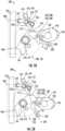
Figure 4A is a partially transparent view of the interaction between a locking lever and a braking lever in an unlocked position in accordance with an example embodiment of the present disclosure; -
Figure 4B is a partially transparent view of the interaction between a locking lever and a braking lever in a locked position in accordance with an example embodiment of the present disclosure; -
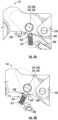
Figure 5A is a partially transparent view of a locking system in an unlocked position in accordance with an example embodiment of the present disclosure; and -
Figure 5B is a partially transparent view of a locking system in a locked position in accordance with an example embodiment of the present disclosure. - Some embodiments will now be described more fully hereinafter with reference to the accompanying drawings, in which some, but not all, embodiments are shown. Indeed, various embodiments may be embodied in many different forms and should not be construed as limited to the embodiments set forth herein; rather, these embodiments are provided so that this disclosure will satisfy applicable legal requirements. As discussed herein, the protection devices may be referred to use by humans, but may also be used to raise and lower objects unless otherwise noted.
- The components illustrated in the figures represent components that may or may not be present in various embodiments of the invention described herein such that embodiments may include fewer or more components than those shown in the figures while not departing from the scope of the invention. Some components may be omitted from one or more figures or shown in dashed line for visibility of the underlying components.
- The present disclosure provides various example locking systems to allow for quick and efficient activation of the braking mechanism to permanently stop the motion of the locking system in at least a first direction. In various embodiments, the locking system allows a user to advantageously use one hand to activate the braking mechanism and to lock it in place via a proximate locking lever. To allow for one hand operation, the components that require activation and locking may be in close proximity to one another. For example, the components may protrude from a housing in substantially the same direction, may be placed at a distance of equal to or less than the distance between the average person's thumb and forefinger, a component, such as the locking lever, may be rotatably coupled to the another component, such as the braking lever, the components may rotate in the same plane when locking and unlocking, and/or the like.
- Referring now to
Figure 1 , an exterior view of thelocking system 100 is provided. Lockingsystem 100, in accordance with an example embodiment, is illustrated in the unlocked position.. In some examples, thelocking system 100 may include abraking lever 110, a lockinglever 115, ahousing 130, and anengagement member 170. - In some embodiments, the
housing 130 may be a unitary piece or have multiple parts, such as shown inFigure 1 . Thehousing 130 includes an end having a substantially curved portion that defines aguide path 160 that is sized to slideably receive a guide member (not shown), such as a rope, a cable, and/or the like. In some embodiments, thehousing 130 includes acover plate 135 configured to cover at least a portion of the locking system components. - In one example embodiment, the housing defines an
aperture 136 that is configured to receive a rivet or pin 155 therethrough so as to operatively couple alocking system 100 to thehousing 130. Thelocking system 100 may include abraking lever 110, which as described herein, is configured to be rotatably attached to the housing by the rivet or pin 155 and rotate about first center of rotation 175, such that abraking surface 140 contacts the a guide member in theguide path 160 so as to arrest its movement in at least one direction. Thebraking lever 110 may include anattachment end 145 opposite thebraking surface 140 that includes anattachment opening 150 to connect a load. Theattachment opening 150 may be reinforced byreinforcement material 165 that may be attached to thebraking lever 110, such as by an attachment pin orrivet 180. In some embodiments, thebraking surface 140 may be a protrusion on the end of thebraking lever 110 opposite of theattachment end 145. In some embodiments, thebraking lever 110 may have asecondary braking surface 141 on the end of thebraking lever 110 opposite theattachment end 145 that is configured to engage with the guide member after thebraking surface 140 engages with the guide member. For example, when a user connected to anexample locking system 100 falls downward at a fast rate, thebraking lever 110 rotates such that both thebraking surface 140 and thesecondary braking surface 141 engage with the guide member slowing and/or halting the speed of the downward movement (e.g., slowing the speed to zero). - In some embodiments, rivet or pin 185 may be configured to connect the
cover plate 135 to the rest of thehousing 130. In some embodiments, the rivet or pin 185 may be configured to restrict the range of motion of thebraking lever 110. For example, the rivet or pin 185 may be located in a position such that the rivet or pin 185 stops the rotation of thebraking lever 110 after thebraking surface 140 engages with the guide member, but before any excessive damage is made to the guide member during engagement. - In some examples, the
locking system 100 may further include a lockinglever 115 operatively coupled to thebraking lever 110. In some embodiments, anactivation end 120 of the lockinglever 115 may protrude outwardly from the locking lever and comprise one or more ridges so as to allow for easy gripping and/or operation. In some examples, the lockinglever 115 may be proximate to theattachment end 145 of thebraking lever 110, such that the locking system may be operated by a user with one hand. In some embodiments, both theactivation end 120 of the lockinglever 115 and theattachment end 145 of thebraking lever 110 may protrude from thehousing 130 in the same or substantially the same direction of the braking lever. Further, and in some examples, thebraking lever 110 and the lockinglever 115 may be configured to rotate in the same plane. - In some embodiments, the
locking system 100 may also include anengagement member 170 configured to engage the guide member at anengagement member wheel 173. In some embodiments, theengagement member 170 may include one or more opening levers 178. In some embodiments, theengagement member 170 may include adivider 172 between one or more opening levers 178. In some embodiments, the opening lever(s) 178 may include anopening lever tab 179 that protrudes from the housing. Theengagement member 170 may be attached to the housing by rivets and/or pins 174, 176. - Referring now to
Figure 2A , an exploded view of thebraking lever 110 and the lockinglever 115, in accordance with some example embodiments, is provided. In some embodiments, thebraking lever 110 includes a distal end that includesbraking surface 140 andsecondary braking surface 141 that are positioned proximate to theguide path 160 and anattachment end 145 that is opposite to the distal end. In some embodiments, thebraking lever 110 may have a generally angled or bent shape (e.g., angle α). - The
braking lever 110 may define one or more, but preferably three openings. In some examples, these openings include a firstrotational opening 205 at or near the proximal end of thebraking lever 110, a secondrotational opening 210 at or near the center of thebraking lever 110, and anattachment opening 150 at or near theattachment end 145. Each of the openings, 150, 205, and 205 define a passage that extends through thebraking lever 110. In some embodiments, aprotrusion 410 may be provided proximate to the secondrotational opening 210 along an edge of thebraking lever 110. Theprotrusion 410, as discussed inFigure 4 , may be configured to engage with the lockinglever 115 when the locking lever is operatively coupled with thebraking lever 110. - In some embodiments, the
braking lever 110 may be operatively attached to thehousing 130 at the first rotational opening, such that the braking lever rotates relative to a first center of rotation 175 (e.g., the center of the first rotational opening 205) that is defined by an axis that is perpendicular to the firstrotational opening 205. In some embodiments, the firstrotational opening 205 may be sized to receive the rivet or pin 155, shown inFigure 1 . - As is described above and in some embodiments, the second
rotational opening 210 may be positioned between the firstrotational opening 205 and theattachment end 145 of thebraking lever 110. In some embodiments, the lockinglever 115 may be operatively coupled to thebraking lever 110 at the secondrotational opening 210, such that the lockinglever 115 rotates relative to the second center of rotation (e.g., the center of the second rotational opening 210). In some embodiments, the secondrotational opening 210 may be configured to receive the lockinglever rivet 220. In some embodiments, the lockinglever rivet 220 is configured to engage with the locking lever opening(s) 225 and the secondrotational opening 210 and also be engaged with arivet ring 230. - In some embodiments, the attachment opening 150 may be reinforced, such as by the
reinforcement material 165 attached (e.g., via the attachment pin or rivet 180) to thebraking lever 110. In some embodiments, theattachment end 145 may be configured to withstand the load attached to thelocking system 100. For example, a rope may be attached (e.g., tied or coupled by way of a carabiner) to the attachment opening 150 at one end of the rope and the other end of the rope may be attached to load (e.g., a person) using thelocking system 100. In some embodiments, the attachment opening 150 may be reinforced, such as shown inFigure 2A , whereinreinforcement material 165 is attached to thebraking lever 110 by the attachment pin orrivet 180. - In some embodiments, the locking
lever 115 may be configured with anactivation end 120 and anengaging end 215. In some embodiments, theactivation end 120 may have a gripping surface that comprises one or more ridges so to allow a user to interact with the lockinglever 115. - In some embodiments, the
engaging end 215 may have a plurality of surfaces. For example, as shown in more detail inFigure 3 , the lockinglever 115 may have arecess 325 that is defined by two protruding portions of the lockinglever 115. In some embodiments, the lockinglever 115 may be angled between theactivation end 120 and the engaging end 215 (e.g., angle β). In some embodiments, the angle between theactivation end 120 and theengaging end 215 may complement the angle of thebraking lever 110. For example, the angle of the lockinglever 115 may be similar to, or in some examples, the same angle as thebraking lever 110, albeit in the opposite direction. In some embodiments, the lockinglever 115 may be sufficiently angled so as to allow for one hand operation. - Referring now to
Figure 2B , thebraking lever 110 and the lockinglever 115 are shown operatively coupled together in accordance with an example embodiment. In some embodiments, the lockinglever 115 may be operatively coupled to thebraking lever 110 about the second center of rotation 235. In some embodiments, an attachment mechanism (e.g., lockinglever rivet 220 and rivet ring 230) may rotatably secure the lockinglever 115 to thebraking lever 110. In an example embodiment, the lockinglever rivet 220 may be configured to pass through one or morelocking lever openings 225 and the secondrotational opening 210, such that the center of the locking lever opening(s) 225, the center of the secondrotational opening 210, and the second center of rotation 235 are all the same point. In some embodiments, theengaging end 215 of the lockinglever 115 may extend beyond thebraking lever 110. - Referring now to
Figure 3 , a transparent view of a locking lever in accordance with an example embodiment is provided. In some embodiments, the locking lever may include arecess 325 that is defined by the twoengaging ends 215 of the lockinglever 115 and aproximal surface 350. In some examples, theproximal surface 350 defines anrecess 325 sized to receive alocking ball 310 and lockinglever spring 315. - In some embodiments, the locking
lever spring 315 may be attached or otherwise coupled to a distal end of therecess 325 at a first end and in communication with the lockingball 310 at the second or opposite end. In some examples, the lockinglever spring 315 biases thelocking ball 310 outwardly and into the recess such that at least a portion of the lockingball 310 extends outwardly beyond the plane defined byproximal surface 350. In some examples, the locking ball is mounted such that in an instance in which a force is applied to thelocking ball 310, the lockingball 310 recedes into therecess 325 until the force is no longer applied. In some embodiments, the lockinglever spring 315 characteristics, such as the spring constant and/or length, may be selected based on the desired resistance of the lockingball 310 to movement. - In some embodiments, the locking
lever 115 may include a radio-frequency identification (RFID) device. For example, the lockinglever 115 may have a compartment configured to receive theRFID device 320. In some examples, theRFID device 320 may send a signal in an instance in which the lockinglever 115 is an unlocked or locked position. Alternatively or additionally, theRFID device 320 may send a signal in an instance in which the lockinglever 115 rotates from an unlocked position to a locked position or vice versa - Referring now to
Figure 4A , the interaction of thebraking lever 110 and the lockinglever 115 is provided in an instance when the locking lever is in the unlocked position (e.g., the activation end of the locking lever is in a first location proximate to theattachment end 145 of thebraking lever 110 such that thebraking surface 140 is not engaged with the guide member 510). In an example embodiment, thebraking lever 110 may include aprotrusion 410 that is sized and shaped to contact the lockingball 310 when the lockinglever 115 is operatively attached to the braking lever. In an unlocked position, such as is shown inFigure 4A , theprotrusion 410 may resist movement of the lockinglever 115. - In some embodiments, the
braking lever 110 may have two locking ball recesses 420 positioned on each side of theprotrusion 410 to receive the locking ball, such that the motion of the lockinglever 115 is limited. In some examples, the locking ball recesses 420 are shaped so as to receive thelocking ball 310 and require a force be applied to the lockinglever 115 to urge the lockingball 310 from a resting position and over a tip of theprotrusion 410. For example, theprotrusion 410 may resist accidental rotation of the locking lever during usage (e.g., the lockinglever 115 may only rotate into the locking position when a user applies force to overcome the lockinglever spring 315 force sufficiently to allow thelocking ball 310 to move from one side of theprotrusion 410 to the other). - Referring now to
Figure 4B , the interaction of thebraking lever 110 and the lockinglever 115 is provided in an instance when the locking lever is in the locked position (e.g., the activation end of the locking lever is in a second location distant to theattachment end 145 of thebraking lever 110 such that thebraking surface 140 is engaged with the guide member 510). In an instance in which the lockinglever 115 is activated in response to the application of a force (e.g., the lockinglever 115 is moved by the user from the first location to the second location to engage theguide member 510 with the braking surface 140), the lockingball 310 may engage with theprotrusion 410, such that the protrusion provides a force opposite to the compression force of the lockinglever spring 315 so as to allow thelocking ball 310 to depressed (e.g., into the opening receiving the locking lever spring 315). In some examples and in instance in which a sufficient force is applied, the lockinglever 115 is able to move from the unlocked position to the locked position. - Referring now to
Figure 5A , a transparent view of thelocking system 100 operatively coupled tohousing 130 is shown. In the example shown inFigure 5A , thebraking lever 110 is shown in a position whereby thebraking surface 140 is not in contact with a guide member. Moreover, the lockinglever 115 is shown in the unlocked position as the lockinglever 115 is positioned at a first location that is proximate to theattachment end 145. In the unlocked position, theguide member 510 may freely traverse in both a first direction and a second direction with no engagement with thebraking surface 140. - In some embodiments, the locking
lever 115 may include an angle of rotation relative to thebraking lever 110 defined as the rotation of the locking lever from a first location (e.g., center line 520) to a second location (e.g., center line of 525). In some examples and in an instance in which the lockinglever 115 is in the unlocked position, the angle of rotation between the lockinglever 115 and thebraking lever 110 is less than 10 degrees, in some examples less than 5 degrees, between zero and three degrees and, in further examples, zero degrees. - In some embodiments, the
engaging end 215 of the lockinglever 115 may be engaged with theengagement member 170. In some embodiments, theengaging end 215 may be engaged with one or more engagement ends 171 of the one or more opening levers 178. In some examples, theengaging end 215 may be tapered to allow for slideable contact betweenae engaging end 215 and anengagement end 171 in an instance in which the lockinglever 115 rotates around the second center of rotation 235. - In some embodiments, the
engagement member 170 may also include anengagement member wheel 173 that is positioned at an end of theengagement member 170 that is opposite to theengagement end 171. In some examples, the opening lever(s) 178 are configured to rotatably engage theguide member 510. - In some embodiments, the
engagement member 170 includes one or more opening levers 178 configured to engage with the lockinglever 115 such that the lockinglever 115 remains in the unlocked position until activated by a user. In some embodiments, theengagement member 170 includes adivider 172 configured to remain fixed during the operation of the one or more opening levers 178. In some embodiments, each openinglever 178 may have anengagement end 171 configured to engage with a lockinglever 115 and one or more engagement member springs 177. In some embodiments, theengagement member wheel 173 may be rotatably coupled with one or more of the opening lever(s) 178 at an end opposite of theengagement end 171. In some embodiments, the engagement member spring(s) 177 of anopening lever 178 may be configured to resist thebraking lever 110 from rotating such that thebraking surface 140 does not disengage from theguide member 510 when the lockinglever 115 is in the locked position. - In an example embodiment, the
engagement member 170 includes two openinglevers 178 on opposing sides of adivider 172 configured to require at least two fingers in order to rotate both openinglevers 178. In some embodiments, theengagement member 170 may remain engaged with the lockinglever 115 with less than all of the opening levers 178 are opened. - In some embodiments, the one or more opening levers 178 may have an
opening lever tab 179 configured to allow the user to rotate the associatedopening lever 178. In some embodiments, the opening lever(s) 178 are configured to allow theguide member 510 to be installed or otherwise inserted when in the opening position, such that thebraking lever 110 is rotated sufficiently to allow the guide member 510 (e.g., a rope) to be placed in theguide member 160 by moving thebraking lever 110 in order to not obstruct the opening between theguide path 160 and thecover plate 135. - Referring now to
Figure 5B, Figure 5B illustrates a transparent view of thelocking system 100 whereby thebraking lever 110 is shown in a position where the braking surface is in contact with a guide member and the lockinglever 115 has been moved to the locked position. In some examples and when in a locked position, the lockinglever 115 is positioned at a second location distant to theattachment end 145 of thebraking lever 110 such that the locking system is locked (e.g., thebraking surface 140 is engaged with theguide member 510 such that the guide member can only move in one direction). - In some embodiments, the locking
lever 115, when activated by a user that is applying a force in an arcuate direction away from the braking lever, may be moved away from theattachment end 145 of thebraking lever 110. - As discussed above in reference to
Figure 4A, 4B , and5A , the lockinglever 115 may rotate about the second center ofrotation 210. In such an example, theengaging end 215 of the lockinglever 115 may rotate with the locking lever such that the engaging end slidedly disengages from the engagement end(s) 171 of theengagement member 170. In some embodiments, theengaging end 215 of the lockinglever 115 may be tapered such that, as the locking lever rotates, the engaging end of the locking lever slides along the engagement end(s) 171 of theengagement member 170 until a point at which theengaging end 215 disengages from the opening lever(s) 178. In an instance when the lockinglever 115 disengages from the opening lever(s), thebraking lever 110 and the lockinglever 115 freely rotate in the same rotational direction until thebraking surface 140 engages with theguide member 510. In some embodiments, the rotation of the braking about the first center of rotation 175 and the rotation of the lockinglever 115 about the second center of rotation 235 are in the same plane. - In an example embodiment, after the locking
lever 115 is moved to the locked position, thebraking lever 110 may be configured with a center of gravity that causes the rotation of thebraking surface 140, as a part of the braking lever, into engagement with theguide member 510. After thebraking surface 140 engages theguide member 510, thelocking system 100 is stopped from traversing theguide member 510 in one direction, while still allowing traversing in the other directions. In an instance where thelocking system 100 attempts to move in a first direction (e.g., the opposite direction as the rotation of the braking lever 110), the rotational force of the braking lever provides a force against the guide member such that thebraking surface 140 remains engaged with theguide member 510. Alternatively, in an instance where thelocking system 100 attempts to move in the other direction (e.g., the same direction as the rotation of the braking lever 110), the force of theguide member 510 is the opposite of the rotational force of thebraking lever 110, such that the braking lever disengages, or partially disengages, theguide member 510 to allow thelocking system 100 to traverse in that direction. - As is shown in
Figure 5B , as a result of the rotation of the lockinglever 115 around the second center of rotation 235, engagingend 215 of the lockinglever 115 has engaged with theengagement end 171 of theengagement member 170 so as to prevent braking lever from rotating about first center of rotation 175. As a result,braking lever 110 is forceably held in a position wherebybraking surface 140 is contact with theguide member 510. In some examples, when thebraking surface 140 is in contact with theguide member 510, movement of theguide member 510 is stopped or otherwise arrested, as is described above. In some embodiments, thebraking lever 110 may also include asecondary braking surface 141, such that thesecondary braking surface 141 is configured to engage theguide member 510 after thebraking surface 140 to provide additional friction to slow down and stop the motion thelocking system 100. - In some embodiments, the
activation end 120 of the lockinglever 115 may have a limited range of motion, such as to allow for one handed activation. For example, theactivation end 120 of the lockinglever 115 may be configured to rotate between a first location defined as the location of the activation end in the unlocked position proximate to theattachment end 145 of the braking lever 110 (e.g., location of activation end inFigure 5A ) and a second location defined as the location of theactivation end 120 in the locked position distant to the attachment end 145 (e.g., location of activation end inFigure 5B ). In some embodiments, the rotational angle may be the angle between the first location and the second location. In some embodiments, the rotational angle may be from zero degrees to 45 degrees. In some embodiments, the rotational angle may be between 10 degrees and 45 degrees. In some embodiments, the rotational angle may be between 20 degrees and 35 degrees. In some embodiments, the rotational angle may be between 25 degrees and 30 degrees. In an example embodiment, the rotational angle may be 30 degrees. In some embodiments, the radial distance from theactivation end 120 at the first location to the position of theactivation end 120 at the second location may be between 0 and 10 inches. In some embodiments, the distance may be between 2 inches and 8 inches, In some embodiments, the distance may be between 3 inches and 7 inches. In some embodiments, the distance may be between 4 inches and 6 inches. In an example embodiment, the distance may be 5 inches. - Many modifications and other embodiments of the inventions set forth herein will come to mind to one skilled in the art to which these inventions pertain having the benefit of the teachings presented in the foregoing descriptions and the associated drawings. Therefore, it is to be understood that the inventions are not to be limited to the specific embodiments disclosed and that modifications and other embodiments are intended to be included within the scope of the appended claims. Moreover, although the foregoing descriptions and the associated drawings describe example embodiments in the context of certain example combinations of elements and/or functions, it should be appreciated that different combinations of elements and/or functions may be provided by alternative embodiments without departing from the scope of the appended claims. In this regard, for example, different combinations of elements and/or functions than those explicitly described above are also contemplated as may be set forth in some of the appended claims. Although specific terms are employed herein, they are used in a generic and descriptive sense only and not for purposes of limitation. Locking systems are described in the following numbered statements:
- Statement 1. A locking system for fall protection, the locking system comprising:
- a housing, wherein the housing defines a guide path through which the housing is slideably attached to a guide member;
- a braking lever having a braking surface and an attachment end, wherein the braking lever is configured to rotate so as to allow a braking surface to engage the guide member; and
- a locking lever that is rotatably coupled to the braking lever,
- wherein in an instance in which the braking surface of the braking lever is disengaged with the guide member, the locking lever is rotatable such that it rotates from an unlocked position to a locked position, and
- wherein in the unlocked position an activation end of the locking lever is positioned in a first location that is proximate to the attachment end and in the locked position the activation end is positioned in a second position distant to the attachment end.
- Statement 2. The locking system of Statement 1, wherein the locking lever and the braking lever rotate in the same radial direction based on the direction of the locking system.
- Statement 3. The locking system of any of Statements 1-2, wherein the braking lever further comprises a protrusion and the locking lever further comprises a locking ball connected to a locking lever spring, wherein the protrusion is in contact with the locking ball so as to restrict rotation of the locking lever from the unlocked position to the locked position.
- Statement 4. The locking system of any of Statements 1-3, wherein the attachment end of the braking lever comprises an attachment opening configured to attach an attachment mechanism.
- Statement 5. The locking system of any of Statements 1-4, wherein the locking system is configured such that in the locking position, the motion of the locking system is restricted in one direction along the guide member.
- Statement 6. The locking system of any of Statements 1-5, wherein the arcuate distance between the attachment end of the braking lever and the first location of the activation end of the locking lever is the distance between the average thumb and forefinger.
- Statement 7. The locking system of any of Statements 1-6, wherein an angle of rotation of the locking lever relative to the braking lever in the unlocked position to the locked position is from 0 degrees to 30 degrees.
- Statement 8. The locking system of any of Statements 1-7, wherein the braking lever is rotatably coupled to the housing at a first point of rotation between the braking surface and the attachment end and the locking lever is rotatably coupled to the braking lever at a second point of rotation between the first point of rotation and the attachment end.
- Statement 9. A locking system for fall protection, the locking system comprising:
- a housing, wherein the housing defines a guide path through which the housing is slideably attached to a guide member;
- a braking lever having a braking surface and an attachment end, wherein the braking lever is operably attached to the housing at a first point of rotation and is configured to rotate so as to allow a braking surface to engage the guide member; and
- a locking lever that is rotatably coupled to the braking lever at a second point of rotation between the first point of rotation and the attachment end,
- wherein in an instance in which the braking surface of the braking lever is disengaged with the guide member, the locking lever is rotatable such that it rotates from an unlocked position to a locked position.
- Statement 10. The locking system of Statement 9, wherein in the unlocked position an end of the locking lever is positioned in a first location that is proximate to the attachment end and in the locked position is positioned in a second position distant to the attachment end.
- Statement 11. The locking system of any of Statements 9-10, wherein an activation end of the locking lever protrudes outwardly from the housing in both the unlocked position and the locked position.
- Statement 12. The locking system of any of Statements 9-11, wherein the locking lever and the braking lever rotate in the same direction based on the direction of the locking system.
- Statement 13. The locking system of any of Statements 9-12, wherein the braking lever further comprises a protrusion and the locking lever further comprises a locking ball connected to a locking lever spring, wherein the protrusion movably engages with the locking ball to restrict rotation of the locking lever from the unlocked position to the locked position.
- Statement 14. The locking system of any of Statements 9-13, wherein the attachment end of the braking lever comprises an attachment opening configured to attach an attachment mechanism.
- Statement 15. The locking system of any of Statements 9-14, wherein the locking system is configured such that in the locking position, the motion of the locking system is restricted in one direction along the guide member.
Claims (10)
- A locking system for fall protection, the locking system comprising:a housing (130), wherein the housing defines a guide path (160) through which the housing is slideably attachable to a guide member (510);a braking lever (110) having a braking surface (140) and an attachment end (145), wherein the braking lever (110) is configured to rotate so as to allow the braking surface (140) to engage the guide member (510); anda locking lever (115) that is rotatably coupled to the braking lever (110), wherein in an instance in which the braking surface (140) of
the braking lever (110) is disengaged with the guide member (510), the locking lever (115) is rotatable such that it rotates from an unlocked position to a locked position, and characterized in that the braking lever (110) further comprises a protrusion (410) and the locking lever (115) further comprises a locking ball (310) connected to a locking lever spring (315), wherein the protrusion (410) is in contact with the locking ball (310) so as to restrict rotation of the locking lever (115) from the unlocked position to the locked position. - The locking system of claim 1, wherein the attachment end of the braking lever (110) comprises an attachment opening (150) configured to attach an attachment mechanism (220, 230).
- The locking system of claim 1 or 2, wherein the locking system is configured such that in the locked position, the motion of the locking system is restricted in one direction along the guide member (510).
- The locking system of any of claims 1 to 3, wherein the locking lever (115) and the braking lever (110) rotate in the same radial direction based on the direction of the locking system.
- The locking system of any of claims 1-4, wherein an angle of rotation of the locking lever (115) relative to the braking lever (110) in the unlocked position to the locked position is from 0 degrees to 30 degrees.
- The locking system of any of claims 1-5, wherein the braking lever (110) is rotatably coupled to the housing at a first center of rotation between the braking surface (140) and the attachment end and the locking lever (115) is rotatably coupled to the braking lever (110) at a second center of rotation between the first point of rotation and the attachment end.
- The locking system claim 1, the locking system comprising: wherein the braking lever (110) is operably attached to the housing at a first point of rotation locking lever (115) is rotatably coupled to the braking lever (110) at a second point of rotation between the first point of rotation and the attachment end.
- The locking system of claim 7, wherein an activation end of the locking lever (115) protrudes outwardly from the housing (130) in both the unlocked position and the locked position.
- The locking system of claim 7 or 8, wherein the locking lever (115) and the braking lever (110) rotate in the same direction based on a direction of the locking system.
- The locking system of any of the preceding claims, wherein the braking lever is attached to the housing and the locking lever is coupled to the braking lever using rivets.
Applications Claiming Priority (2)
| Application Number | Priority Date | Filing Date | Title |
|---|---|---|---|
| US16/399,471 US11648967B2 (en) | 2019-04-30 | 2019-04-30 | Fall protection locking systems |
| EP20169983.2A EP3733245B1 (en) | 2019-04-30 | 2020-04-16 | Fall protection locking system |
Related Parent Applications (2)
| Application Number | Title | Priority Date | Filing Date |
|---|---|---|---|
| EP20169983.2A Division EP3733245B1 (en) | 2019-04-30 | 2020-04-16 | Fall protection locking system |
| EP20169983.2A Division-Into EP3733245B1 (en) | 2019-04-30 | 2020-04-16 | Fall protection locking system |
Publications (2)
| Publication Number | Publication Date |
|---|---|
| EP4375159A2 true EP4375159A2 (en) | 2024-05-29 |
| EP4375159A3 EP4375159A3 (en) | 2024-08-14 |
Family
ID=70294967
Family Applications (2)
| Application Number | Title | Priority Date | Filing Date |
|---|---|---|---|
| EP20169983.2A Active EP3733245B1 (en) | 2019-04-30 | 2020-04-16 | Fall protection locking system |
| EP24170864.3A Pending EP4375159A3 (en) | 2019-04-30 | 2020-04-16 | Fall protection locking system |
Family Applications Before (1)
| Application Number | Title | Priority Date | Filing Date |
|---|---|---|---|
| EP20169983.2A Active EP3733245B1 (en) | 2019-04-30 | 2020-04-16 | Fall protection locking system |
Country Status (2)
| Country | Link |
|---|---|
| US (1) | US11648967B2 (en) |
| EP (2) | EP3733245B1 (en) |
Families Citing this family (10)
| Publication number | Priority date | Publication date | Assignee | Title |
|---|---|---|---|---|
| CN111840851B (en) * | 2020-08-18 | 2025-08-01 | 中际联合(北京)科技股份有限公司 | Rope locking device |
| CA3198494A1 (en) * | 2020-11-19 | 2022-05-27 | Bradley Burke | Fall control system and method of controlling a movement during fall event |
| US20220178412A1 (en) * | 2020-12-09 | 2022-06-09 | Sherrill, Inc. | Rigid Friction Brake Tether |
| EP4159288A1 (en) * | 2021-09-30 | 2023-04-05 | Fam Service S.r.l. | Anti-fall individual protection device and process for safely accessing a raised surface by means of said device |
| CA3223498A1 (en) * | 2021-11-19 | 2023-05-25 | Checkmate Lifting & Safety Ltd | Cable sleeve |
| US12415101B2 (en) * | 2022-05-24 | 2025-09-16 | Honeywell Safety Products Usa, Inc. | Fall protection shuttle apparatus and methods of using the same |
| US20230415795A1 (en) * | 2022-06-22 | 2023-12-28 | Michael Troy Richardson | Zipline braking system with passive braking trolley |
| USD1096366S1 (en) * | 2023-05-08 | 2025-10-07 | Honeywell Safety Products Usa, Inc. | Fall protection arrester |
| CN119656506A (en) * | 2025-01-02 | 2025-03-21 | 广东四维科技有限公司 | A self-locking device to prevent falling |
| KR102890996B1 (en) * | 2025-03-05 | 2025-12-01 | 주식회사 이에스시스템 | Wire contact area open/closed fall arrestor |
Family Cites Families (12)
| Publication number | Priority date | Publication date | Assignee | Title |
|---|---|---|---|---|
| FR2720283B1 (en) * | 1994-04-21 | 1996-08-23 | Froment Sa | Anti-fall device locks automatically on a safety rope. |
| ITMI20050012U1 (en) | 2005-01-21 | 2006-07-22 | Aludesign Spa | CLAMP-LOCKING DEVICE FOR CLIMBING |
| FR2898506B1 (en) * | 2006-03-15 | 2008-05-30 | Zedel Soc Par Actions Simplifi | MULTI-FUNCTIONAL ROPE INSURANCE APPARATUS |
| US7533871B1 (en) * | 2006-11-07 | 2009-05-19 | Everett Perry L | Rope control apparatus |
| DE102008028647A1 (en) | 2008-06-18 | 2009-12-24 | Bornack Gmbh & Co. Kg | Running fall arrester |
| DE202008010819U1 (en) * | 2008-08-05 | 2008-10-16 | Skylotec Gmbh | Fall arrester with speed-dependent clutch |
| DE102012207223B3 (en) * | 2012-04-30 | 2013-09-26 | Bornack Gmbh & Co. Kg | safety device |
| US10760336B2 (en) * | 2013-06-28 | 2020-09-01 | 3M Innovative Properties Company | Fall arrester |
| WO2016093850A1 (en) | 2014-12-12 | 2016-06-16 | Honeywell International Inc. | Shuttle for a climbing protection system |
| NL2016911B1 (en) | 2016-02-05 | 2017-08-21 | Xsplatforms B V | Device for stopping a fall while climbing or descending along a cable |
| US9874034B2 (en) * | 2016-03-10 | 2018-01-23 | Meyer Ostrobrod | Anti-panic cable grab |
| US10035028B1 (en) * | 2017-01-04 | 2018-07-31 | Mallory Safety+Supply | Emergency descender device |
-
2019
- 2019-04-30 US US16/399,471 patent/US11648967B2/en active Active
-
2020
- 2020-04-16 EP EP20169983.2A patent/EP3733245B1/en active Active
- 2020-04-16 EP EP24170864.3A patent/EP4375159A3/en active Pending
Also Published As
| Publication number | Publication date |
|---|---|
| EP3733245A1 (en) | 2020-11-04 |
| EP3733245B1 (en) | 2024-06-05 |
| US11648967B2 (en) | 2023-05-16 |
| EP4375159A3 (en) | 2024-08-14 |
| US20200346671A1 (en) | 2020-11-05 |
Similar Documents
| Publication | Publication Date | Title |
|---|---|---|
| US11648967B2 (en) | Fall protection locking systems | |
| US10737125B2 (en) | Fall arrest device | |
| EP3851697B1 (en) | Fall protection locking system and method for manufacturing same | |
| US7946006B2 (en) | Carabiner having dual gates and associated methods | |
| EP3815748B1 (en) | Bendable housing for fall protection locking system | |
| US11660475B2 (en) | High load descender with adaptive release linkage | |
| JP5731540B2 (en) | Fall prevention safety device with braking mechanism | |
| US9192792B2 (en) | Fall arrest safety apparatus with blocking on a rope | |
| US5975243A (en) | Jamming device for rope and alike | |
| US7845467B2 (en) | Multifunctional belaying device for a rope | |
| CA2732198C (en) | Catching device having a speed-dependent coupling | |
| CA2563449C (en) | Rotary locking mechanism for outside vehicle door handle | |
| EP2555907B1 (en) | Adjustable handle assembly with locking mechanism | |
| EP3678507B1 (en) | Harness connector | |
| US6601274B2 (en) | Static line snap | |
| US20110100755A1 (en) | Brake assembly for a self-retracting lifeline assembly | |
| US20140262610A1 (en) | Systems for Assisted Braking Belay with a Lever Disengagement Mechanism | |
| WO2020159920A1 (en) | Clevis-sensing adjustable hook latch | |
| WO2008135492A2 (en) | Guiding rail for a cabinet pull-out part | |
| EP1596941B1 (en) | Safety devices | |
| US2791817A (en) | Lineman's safety hook | |
| CN111790074B (en) | Braking mechanism of protective device | |
| GB1582667A (en) | Selflocking door handle assembly | |
| EP4454718A1 (en) | Locking pulley for ropes | |
| US1601620A (en) | Safety attachment for valve structures |
Legal Events
| Date | Code | Title | Description |
|---|---|---|---|
| PUAI | Public reference made under article 153(3) epc to a published international application that has entered the european phase |
Free format text: ORIGINAL CODE: 0009012 |
|
| STAA | Information on the status of an ep patent application or granted ep patent |
Free format text: STATUS: THE APPLICATION HAS BEEN PUBLISHED |
|
| AC | Divisional application: reference to earlier application |
Ref document number: 3733245 Country of ref document: EP Kind code of ref document: P |
|
| AK | Designated contracting states |
Kind code of ref document: A2 Designated state(s): AL AT BE BG CH CY CZ DE DK EE ES FI FR GB GR HR HU IE IS IT LI LT LU LV MC MK MT NL NO PL PT RO RS SE SI SK SM TR |
|
| REG | Reference to a national code |
Ref country code: DE Ref legal event code: R079 Free format text: PREVIOUS MAIN CLASS: B61H0009020000 Ipc: A62B0035000000 |
|
| PUAL | Search report despatched |
Free format text: ORIGINAL CODE: 0009013 |
|
| AK | Designated contracting states |
Kind code of ref document: A3 Designated state(s): AL AT BE BG CH CY CZ DE DK EE ES FI FR GB GR HR HU IE IS IT LI LT LU LV MC MK MT NL NO PL PT RO RS SE SI SK SM TR |
|
| RIC1 | Information provided on ipc code assigned before grant |
Ipc: B61H 9/02 20060101ALI20240711BHEP Ipc: A62B 1/14 20060101ALI20240711BHEP Ipc: F16D 63/00 20060101ALI20240711BHEP Ipc: A62B 35/00 20060101AFI20240711BHEP |
|
| STAA | Information on the status of an ep patent application or granted ep patent |
Free format text: STATUS: REQUEST FOR EXAMINATION WAS MADE |
|
| 17P | Request for examination filed |
Effective date: 20250218 |
|
| RAP1 | Party data changed (applicant data changed or rights of an application transferred) |
Owner name: HONEYWELL SAFETY PRODUCTS USA, INC. |