EP4375130A1 - Crawler vehicle and method for managing the operation of said crawler vehicle - Google Patents
Crawler vehicle and method for managing the operation of said crawler vehicle Download PDFInfo
- Publication number
- EP4375130A1 EP4375130A1 EP23211922.2A EP23211922A EP4375130A1 EP 4375130 A1 EP4375130 A1 EP 4375130A1 EP 23211922 A EP23211922 A EP 23211922A EP 4375130 A1 EP4375130 A1 EP 4375130A1
- Authority
- EP
- European Patent Office
- Prior art keywords
- energy storage
- storage assembly
- crawler vehicle
- connection interface
- propulsion system
- Prior art date
- Legal status (The legal status is an assumption and is not a legal conclusion. Google has not performed a legal analysis and makes no representation as to the accuracy of the status listed.)
- Pending
Links
- 238000000034 method Methods 0.000 title claims description 13
- 238000004146 energy storage Methods 0.000 claims abstract description 111
- 230000005540 biological transmission Effects 0.000 claims abstract description 6
- 239000001257 hydrogen Substances 0.000 claims description 5
- 229910052739 hydrogen Inorganic materials 0.000 claims description 5
- UFHFLCQGNIYNRP-UHFFFAOYSA-N Hydrogen Chemical compound [H][H] UFHFLCQGNIYNRP-UHFFFAOYSA-N 0.000 claims description 3
- 230000008878 coupling Effects 0.000 claims description 2
- 238000010168 coupling process Methods 0.000 claims description 2
- 238000005859 coupling reaction Methods 0.000 claims description 2
- 238000002485 combustion reaction Methods 0.000 description 5
- 239000007789 gas Substances 0.000 description 2
- 238000003306 harvesting Methods 0.000 description 2
- 150000002431 hydrogen Chemical class 0.000 description 2
- 241000609240 Ambelania acida Species 0.000 description 1
- 241000196324 Embryophyta Species 0.000 description 1
- 230000000712 assembly Effects 0.000 description 1
- 238000000429 assembly Methods 0.000 description 1
- 239000010905 bagasse Substances 0.000 description 1
- 238000006243 chemical reaction Methods 0.000 description 1
- 238000004891 communication Methods 0.000 description 1
- 230000009191 jumping Effects 0.000 description 1
- 230000009347 mechanical transmission Effects 0.000 description 1
- 239000002362 mulch Substances 0.000 description 1
- 238000002360 preparation method Methods 0.000 description 1
Images




Classifications
-
- B—PERFORMING OPERATIONS; TRANSPORTING
- B60—VEHICLES IN GENERAL
- B60L—PROPULSION OF ELECTRICALLY-PROPELLED VEHICLES; SUPPLYING ELECTRIC POWER FOR AUXILIARY EQUIPMENT OF ELECTRICALLY-PROPELLED VEHICLES; ELECTRODYNAMIC BRAKE SYSTEMS FOR VEHICLES IN GENERAL; MAGNETIC SUSPENSION OR LEVITATION FOR VEHICLES; MONITORING OPERATING VARIABLES OF ELECTRICALLY-PROPELLED VEHICLES; ELECTRIC SAFETY DEVICES FOR ELECTRICALLY-PROPELLED VEHICLES
- B60L53/00—Methods of charging batteries, specially adapted for electric vehicles; Charging stations or on-board charging equipment therefor; Exchange of energy storage elements in electric vehicles
- B60L53/80—Exchanging energy storage elements, e.g. removable batteries
-
- B—PERFORMING OPERATIONS; TRANSPORTING
- B62—LAND VEHICLES FOR TRAVELLING OTHERWISE THAN ON RAILS
- B62D—MOTOR VEHICLES; TRAILERS
- B62D55/00—Endless track vehicles
- B62D55/06—Endless track vehicles with tracks without ground wheels
- B62D55/065—Multi-track vehicles, i.e. more than two tracks
-
- B—PERFORMING OPERATIONS; TRANSPORTING
- B60—VEHICLES IN GENERAL
- B60L—PROPULSION OF ELECTRICALLY-PROPELLED VEHICLES; SUPPLYING ELECTRIC POWER FOR AUXILIARY EQUIPMENT OF ELECTRICALLY-PROPELLED VEHICLES; ELECTRODYNAMIC BRAKE SYSTEMS FOR VEHICLES IN GENERAL; MAGNETIC SUSPENSION OR LEVITATION FOR VEHICLES; MONITORING OPERATING VARIABLES OF ELECTRICALLY-PROPELLED VEHICLES; ELECTRIC SAFETY DEVICES FOR ELECTRICALLY-PROPELLED VEHICLES
- B60L50/00—Electric propulsion with power supplied within the vehicle
- B60L50/50—Electric propulsion with power supplied within the vehicle using propulsion power supplied by batteries or fuel cells
- B60L50/60—Electric propulsion with power supplied within the vehicle using propulsion power supplied by batteries or fuel cells using power supplied by batteries
-
- B—PERFORMING OPERATIONS; TRANSPORTING
- B60—VEHICLES IN GENERAL
- B60S—SERVICING, CLEANING, REPAIRING, SUPPORTING, LIFTING, OR MANOEUVRING OF VEHICLES, NOT OTHERWISE PROVIDED FOR
- B60S5/00—Servicing, maintaining, repairing, or refitting of vehicles
- B60S5/06—Supplying batteries to, or removing batteries from, vehicles
-
- B—PERFORMING OPERATIONS; TRANSPORTING
- B62—LAND VEHICLES FOR TRAVELLING OTHERWISE THAN ON RAILS
- B62D—MOTOR VEHICLES; TRAILERS
- B62D55/00—Endless track vehicles
- B62D55/08—Endless track units; Parts thereof
-
- E—FIXED CONSTRUCTIONS
- E02—HYDRAULIC ENGINEERING; FOUNDATIONS; SOIL SHIFTING
- E02F—DREDGING; SOIL-SHIFTING
- E02F9/00—Component parts of dredgers or soil-shifting machines, not restricted to one of the kinds covered by groups E02F3/00 - E02F7/00
- E02F9/20—Drives; Control devices
- E02F9/2058—Electric or electro-mechanical or mechanical control devices of vehicle sub-units
- E02F9/2062—Control of propulsion units
- E02F9/2075—Control of propulsion units of the hybrid type
-
- E—FIXED CONSTRUCTIONS
- E02—HYDRAULIC ENGINEERING; FOUNDATIONS; SOIL SHIFTING
- E02F—DREDGING; SOIL-SHIFTING
- E02F9/00—Component parts of dredgers or soil-shifting machines, not restricted to one of the kinds covered by groups E02F3/00 - E02F7/00
- E02F9/20—Drives; Control devices
- E02F9/2058—Electric or electro-mechanical or mechanical control devices of vehicle sub-units
- E02F9/2091—Control of energy storage means for electrical energy, e.g. battery or capacitors
-
- E—FIXED CONSTRUCTIONS
- E02—HYDRAULIC ENGINEERING; FOUNDATIONS; SOIL SHIFTING
- E02F—DREDGING; SOIL-SHIFTING
- E02F9/00—Component parts of dredgers or soil-shifting machines, not restricted to one of the kinds covered by groups E02F3/00 - E02F7/00
- E02F9/20—Drives; Control devices
- E02F9/22—Hydraulic or pneumatic drives
-
- B—PERFORMING OPERATIONS; TRANSPORTING
- B60—VEHICLES IN GENERAL
- B60L—PROPULSION OF ELECTRICALLY-PROPELLED VEHICLES; SUPPLYING ELECTRIC POWER FOR AUXILIARY EQUIPMENT OF ELECTRICALLY-PROPELLED VEHICLES; ELECTRODYNAMIC BRAKE SYSTEMS FOR VEHICLES IN GENERAL; MAGNETIC SUSPENSION OR LEVITATION FOR VEHICLES; MONITORING OPERATING VARIABLES OF ELECTRICALLY-PROPELLED VEHICLES; ELECTRIC SAFETY DEVICES FOR ELECTRICALLY-PROPELLED VEHICLES
- B60L2200/00—Type of vehicles
- B60L2200/40—Working vehicles
-
- E—FIXED CONSTRUCTIONS
- E01—CONSTRUCTION OF ROADS, RAILWAYS, OR BRIDGES
- E01H—STREET CLEANING; CLEANING OF PERMANENT WAYS; CLEANING BEACHES; DISPERSING OR PREVENTING FOG IN GENERAL CLEANING STREET OR RAILWAY FURNITURE OR TUNNEL WALLS
- E01H4/00—Working on surfaces of snow or ice in order to make them suitable for traffic or sporting purposes, e.g. by compacting snow
- E01H4/02—Working on surfaces of snow or ice in order to make them suitable for traffic or sporting purposes, e.g. by compacting snow for sporting purposes, e.g. preparation of ski trails; Construction of artificial surfacings for snow or ice sports ; Trails specially adapted for on-the-snow vehicles, e.g. devices adapted for ski-trails
Definitions
- the invention relates to a crawler vehicle, in particular for preparing ski runs, and to a method for managing the operation of said crawler vehicle.
- a crawler vehicle of the type identified above comprises a frame; a cabin mounted on the frame; a propulsion system mounted on the frame; drive wheels operated by the propulsion system; and work tools powered by the propulsion system.
- the propulsion system of the aforesaid crawler vehicle typically comprises an internal combustion engine, a supply pump, a mechanical transmission configured to transmit power from the internal combustion engine to the supply pump and hydraulic actuators, which are supplied by the supply pump and are configured to operate the drive wheels and the work tools.
- the internal combustion engine emits polluting exhaust gases.
- a further drawback of known crawler vehicles lies in the scarce energy efficiency caused by the difficulty in controlling the power delivered by the internal combustion engine so as to have the internal combustion engine operate at its maximum efficiency point regardless of the energy need of the crawler vehicle.
- the object of the invention is to provide a crawler vehicle, in particular for preparing ski runs, which reduces the drawbacks of the prior art discussed above.
- the object of the invention is to provide a crawler vehicle of the aforesaid type, which solves the technical drawback of the long charging times of the powering system.
- a crawler vehicle in particular for preparing ski runs, the crawler vehicle comprising:
- the first energy storage assembly when the first power storage assembly is substantially discharged, the first energy storage assembly can be replaced by a further first energy storage assembly in a simple and quick manner, with no need to wait for the time needed by the first energy storage system to be recharged. In this way, standstill times, during which the crawler vehicle cannot operate, are significantly reduced.
- the first energy storage assembly comprises a first mechanical connector and a first power connector; the connection interface comprising a second mechanical connector configured to engage, in a releasable manner, the first mechanical connector and a second power connector configured to be connected to the first power connector so as to transmit power to the propulsion system.
- connection/disconnection operations between the first energy storage assembly and the connection interface can be automated and/or be carried by an operator.
- the crawler vehicle comprises a cabin mounted on the frame; the connection interface being arranged behind the cabin with respect to a travelling direction of the crawler vehicle.
- the first energy storage assembly can be connected/disconnected to/from the back of the cabin.
- connection interface comprises at least one guide; the first energy storage assembly comprising at least one sliding element, which is configured to slide along the respective guide so as to connect/disconnect the first energy storage assembly to/from the connection interface.
- the crawler vehicle comprises a position sensor assembly configured to detect the relative position of the connection interface with respect to a replacement device of the first energy storage assembly; the position sensor assembly preferably comprising a lidar and/or a radar and/or a video camera and/or a GPS sensor.
- a position signal can be delivered to a control unit in order to automate the operations to be carried out to connect/disconnect the first energy storage assembly to/from the connection interface, so as to automatically control the positioning of the connection interface relative to the replacement device.
- a position signal can be delivered to an operator so as to allow the operator to check for the correct positioning of the connection interface relative to the replacement device.
- the crawler vehicle comprises a second energy storage assembly, which is configured to be removed from the crawler vehicle and to be replaced by a further second energy storage assembly, and a further connection interface, which is preferably arranged under the cabin and is configured to selectively connect/disconnect the second energy storage assembly to/from the propulsion system in a quick manner.
- the propulsion system can be powered through the second energy storage system and the second energy storage system can be connected/disconnected to/from the further connection interface under the cabin.
- each energy storage assembly comprises at least one battery for storing electrical energy, so as to power propulsion system with electrical energy.
- each energy storage assembly comprises at least one tank for storing hydrogen, so as to power propulsion system with hydrogen.
- a further object of the invention is to provide a method for managing the operation of a crawler vehicle, which reduces the drawbacks of the prior art discussed above.
- a crawler vehicle preferably for preparing ski runs, the method comprising the steps of:
- the discharged energy storage assembly can easily and quickly be removed and replaced when needed, thus minimizing standstill times, during which the crawler vehicle cannot operate.
- number 1 indicates, as a whole, a crawler vehicle for preparing ski runs.
- the crawler vehicle 1 is a snow groomer.
- the crawler vehicle 1 is used for the preparation of ski runs for Alpine skiing and/or ski runs for cross-country skiing and/or ramps for ski jumping and/or half-pipes and/or snow-parks.
- the crawler vehicle 1 can be used in agricultural operations, such as for example the harvesting and/or the handling of agricultural products and/or the ensilage of fodder and/or the harvesting and/or the handling of bagasse.
- the crawler vehicle 1 can comprise a mulcher arranged on the front side of the crawler vehicle 1 and can be used to mulch plants.
- the crawler vehicle 1 comprises a frame 2; a track 3 ( Figure 3 ); a track 4; a drive wheel 5 ( Figure 3 ) and a drive wheel 6 independent of one another and coupled to the track 3 ( Figure 3 ) and to the track 4, respectively, in order to operate the track 3 ( Figure 3 ) and the track 4, respectively; a plurality of hydraulically operated tools 7 connected to the frame 2; a cabin 8 mounted on the frame 2; and a user interface 9 arranged inside the cabin 8.
- the tools 7 comprise a tiller 10, which is connected to the frame 2 in a movable manner and is operated by a hydraulic motor 11 ( Figure 3 ), and a shovel 12, which is connected to the frame 2 in a movable manner and is operated by a hydraulic motor 13 ( Figure 3 ).
- hydraulic motor indicates any device for the conversion of hydraulic power into mechanical power and encloses, in its meaning, any type of hydraulic actuator and hydraulic cylinder.
- the cabin 8 is arranged in the front part of the crawler vehicle 1 and faces the shovel 12 in a travelling direction D.
- the crawler vehicle 1 comprises an energy storage assembly 14 configured to be removed from the crawler vehicle 1 and to be replaced by a further energy storage assembly 14; a propulsion system 15 configured to be powered by the energy storage system 14; a connection interface 16 configured to selectively and quickly connect/disconnect the energy storage assembly 14 to/from the propulsion system 15; and a transmission assembly 17 configured to transmit power from the propulsion system 15 to the drive wheels 5 and 6 and to the hydraulic motors 11 and 13 ( Figure 3 ).
- connection interface 16 is arranged behind the cabin 8 with respect to the travelling direction D of the crawler vehicle 1. More in detail, the connection interface 16 is fixed on the frame 2 behind the cabin 8.
- the crawler vehicle 1 comprises an energy storage assembly 18, which is configured to be removed from the crawler vehicle 1 and to be replaced by a further energy storage assembly 18, and a connection interface 19, which is preferably arranged under the cabin 8 and is configured to selectively connect/disconnect the energy storage assembly 18 to/from the propulsion system 15 in a quick manner.
- connection interface 19 is fixed on the frame 2 under the cabin 8.
- the crawler vehicle 1 only comprise the energy storage assembly 14 and the connection interface 16 and lacks the energy storage assembly 18 and the connection interface 19.
- the crawler vehicle 1 only comprise the energy storage assembly 18 and the connection interface 19 and lacks the energy storage assembly 14 and the connection interface 16.
- the energy storage assembly 14 comprises a support element 20, which is provided with a mechanical connector 21 and with a power connector 22 to be coupled to the connection interface 16.
- connection interface 16 comprises a mechanical connector 23 configured to engage, in a releasable manner, the mechanical connector 21 of the energy storage assembly 14 and a power connector 24 configured to be connected to the power connector 22 of the energy storage assembly 14 so as to transmit power to the propulsion system 15.
- the energy storage assembly 14 comprises at least one battery 25 for storing electrical energy.
- the energy storage assembly 14 comprises a plurality of batteries 25 fixed to the support element 20.
- the propulsion system 15 comprises an electric motor.
- the energy storage assembly 18 comprises a support element 26, which is provided with a mechanical connector 27 and with a power connector 28 to be coupled to the connection interface 19.
- connection interface 19 comprises a mechanical connector 29 configured to engage, in a releasable manner, the mechanical connector 27 of the energy storage assembly 18 and a power connector 30 configured to be connected to the power connector 28 of the energy storage assembly 18 so as to transmit power to the propulsion system 15.
- the energy storage assembly 18 also comprises at least one battery 31 for storing electrical energy.
- the energy storage assembly 18 comprises a plurality of batteries 31 fixed to the support element 26.
- the power connectors 22 and 24 and the power connectors 28 and 30 are electrical connectors configured to be electrically connected to one another so as to transmit electrical power to the propulsion system 15.
- the mechanical connectors 21, 23, 27 and 29 are quick coupling and release connectors According to an alternative embodiment, the mechanical connectors 21, 23, 27 and 29 comprise fixing means, such as for example screws and bolts.
- connection interface 16 comprises at least one guide 32.
- the energy storage assembly 14 comprises at least one sliding element 33, which is configured to slide along the respective guide 32 so as to connect/disconnect the energy storage assembly 14 to/from the connection interface 16.
- connection interface 16 comprises two guides 32, each extending along a respective longitudinal axis A substantially parallel to the travelling direction D.
- the crawler vehicle 1 comprises a position sensor assembly 34 configured to detect the relative position of the connection interface 16 and/or of the connection interface 19 with respect to a respective replacement device 35, 36, which is configured to remove the respective energy storage assembly 14, 18 from the connection interface 16, 19 and to replace the removed energy storage assembly 14, 18 with a respective further energy storage assembly 14, 18.
- the position sensor assembly 34 comprises a lidar and/or a radar and/or a video camera and/or a GPS sensor.
- the crawler vehicle 1 further comprises a control unit 37, which is in communication with the position sensor assembly 34 and is configured to control the position of the crawler vehicle 1 relative to the replacement device 35 or to the replacement device 36 depending on the relative position detected by the sensor assembly 34.
- a control unit 37 which is in communication with the position sensor assembly 34 and is configured to control the position of the crawler vehicle 1 relative to the replacement device 35 or to the replacement device 36 depending on the relative position detected by the sensor assembly 34.
- the user interface 9 comprises an indicator 38 configured to emit a signal indicative of the relative position detected by the position sensor assembly 34.
- control assembly 37 comprises a charge sensor 39 configured to acquire the level of charge of the energy storage assemblies 14 and/or 18.
- the user interface 9 comprises an indicator 40 configured to emit a signal indicative of the level of charge acquired by the charge sensor 39.
- the user interface 9 is a graphic interface, such as for example a screen, configured to display the indicators 38 and 40 so as to inform an operator controlling the crawler vehicle 1.
- the replacement device 35 can comprise an automated equipment, such as for example a manipulator, or a crane.
- the replacement device 36 can comprise an automatic apparatus that can selectively be lifted/lowered from/to the ground.
- Figure 2 shown a further embodiment of the invention, in which the crawler vehicle 1 is not provided with the energy storage assembly 18 and with the connection interface 19 and comprises an energy storage assembly 41 provided with at least one tank 42 to contain hydrogen (H 2 ).
- the energy storage assembly 41 comprises a plurality of tanks 42 fixed to the support element 20.
- the propulsion system 15 comprises a hydrogen motor.
- the transmission assembly 17 comprises a hydraulic system 43, which is powered by the propulsion system 15 and is configured to transmit power to the drive wheels 5 and 6 and to the hydraulic motors 11 and 13.
- the hydraulic system 43 comprises a plurality of pumps.
- the crawler vehicle 1 is led to a replacement area, where the replacement device 35 is located so as to remove and replace the energy storage assembly 14.
- the position sensor assembly 34 detects the relative position of the connection interface 16 with respect to the replacement device 35 and the control unit 37 controls the position of the crawler vehicle 1 with respect to the replacement device 35 as a function of the relative position detected by the position sensor assembly 34.
- the indicator 38 of the user interface 9 emits a signal indicative of the relative position detected by the position sensor assembly 34 so as to allow the operator of the crawler vehicle 1 to check for the correct positioning of the connection interface 16.
- the replacement device 35 starts the sliding of the discharged energy storage assembly 14 along the guides 32 so as to disconnect the mechanical connectors 21 and 23 and the power connectors 22 and 24 from one another and remove the discharged energy storage assembly 14 from the connection interface 16.
- the replacement device 35 connects a further charged energy storage assembly 14 to the connection interface 16.
- the replacement device 35 starts the sliding of the further charged energy storage assembly 14 along the guides 32, until the mechanical connectors 21 and 23 and the power connectors 22 and 24 are connected to one another.
- the crawler vehicle 1 is led to a replacement area, where the replacement device 36 is located so as to remove and replace the energy storage assembly 18.
- connection interface 19 is correctly positioned above the replacement device 36, the replacement device 36 is lifted from the ground until it engages the energy storage assembly 18.
- the replacement device 36 is moved downwards so as to disconnect the mechanical connectors 27 and 29 and the power connectors 28 and 30 from one another and remove the discharged energy storage assembly 18 from under the cabin 8.
- the replacement device 36 connects a further charged energy storage assembly 18 to the connection interface 19.
- said further charged energy storage system 18 is coupled to an upper end of the replacement device 36, which is lifted again from the ground until the mechanical connectors 27 and 29 and the power connectors 28 and 30 are connected to one another.
- Figure 6 shows a variant of the invention, in which the crawler vehicle 1 comprises an energy storage assembly 44, which is is not provided with sliding elements, and a connection interface 45, which is not provided with guides.
- the crawler vehicle 1 is led to a replacement area, where a replacement device 46 is located so as to remove and replace the energy storage assembly 44.
- the replacement device 46 comprises a lifting system 47, such as for example a crane, configured to vertically lift and lower the energy storage assembly 44 relative to the connection interface 45.
- a lifting system 47 such as for example a crane
- connection interface 45 is correctly positioned relative to the replacement device 46, the lifting system 47 is connected to the energy storage assembly 44.
- the lifting system 47 is operated so as to lift the discharged energy storage assembly 44 relative to the connection interface 45, thus disconnecting the mechanical connectors 21 and 23 and the power connectors 22 and 24 from one another.
- the lifting system 47 lowers a further charged energy storage assembly 44 onto the connection interface 45 so as to connect said further charged energy storage assembly 44 to the propulsion system 15.
Landscapes
- Engineering & Computer Science (AREA)
- Mechanical Engineering (AREA)
- Transportation (AREA)
- Power Engineering (AREA)
- General Engineering & Computer Science (AREA)
- Structural Engineering (AREA)
- Civil Engineering (AREA)
- Mining & Mineral Resources (AREA)
- Chemical & Material Sciences (AREA)
- Combustion & Propulsion (AREA)
- Life Sciences & Earth Sciences (AREA)
- Sustainable Development (AREA)
- Sustainable Energy (AREA)
- Electric Propulsion And Braking For Vehicles (AREA)
Abstract
Description
- This patent application claims priority from
Italian patent application no. 102022000024399 filed on November 25, 2022 - The invention relates to a crawler vehicle, in particular for preparing ski runs, and to a method for managing the operation of said crawler vehicle.
- Generally speaking, a crawler vehicle of the type identified above comprises a frame; a cabin mounted on the frame; a propulsion system mounted on the frame; drive wheels operated by the propulsion system; and work tools powered by the propulsion system.
- The propulsion system of the aforesaid crawler vehicle typically comprises an internal combustion engine, a supply pump, a mechanical transmission configured to transmit power from the internal combustion engine to the supply pump and hydraulic actuators, which are supplied by the supply pump and are configured to operate the drive wheels and the work tools. In this configuration, the internal combustion engine emits polluting exhaust gases. A further drawback of known crawler vehicles lies in the scarce energy efficiency caused by the difficulty in controlling the power delivered by the internal combustion engine so as to have the internal combustion engine operate at its maximum efficiency point regardless of the energy need of the crawler vehicle.
- In the last decades, the increasing attention towards global pollution reduction has led to the development of crawler vehicles powered by alternative powering systems, such as, for example, electric batteries.
- Generally speaking, alternative powering systems allow for a highly efficient energy transmission and lead to zero emissions of polluting gases, though they require long charging times.
- The object of the invention is to provide a crawler vehicle, in particular for preparing ski runs, which reduces the drawbacks of the prior art discussed above.
- In particular, the object of the invention is to provide a crawler vehicle of the aforesaid type, which solves the technical drawback of the long charging times of the powering system.
- According to the invention, there is provided a crawler vehicle, in particular for preparing ski runs, the crawler vehicle comprising:
- a frame;
- a first energy storage assembly configured to be removed from the crawler vehicle and to be replaced by a further first energy storage assembly;
- a propulsion system configured to be powered by the first energy storage assembly;
- a connection interface configured to selectively and quickly connect/disconnect the first energy storage assembly to/from the propulsion system;
- a first motorised track and a second motorised track; and
- a transmission assembly configured to transmit power from the propulsion system to the first and to the second track.
- Thanks to this invention, when the first power storage assembly is substantially discharged, the first energy storage assembly can be replaced by a further first energy storage assembly in a simple and quick manner, with no need to wait for the time needed by the first energy storage system to be recharged. In this way, standstill times, during which the crawler vehicle cannot operate, are significantly reduced.
- In particular, the first energy storage assembly comprises a first mechanical connector and a first power connector; the connection interface comprising a second mechanical connector configured to engage, in a releasable manner, the first mechanical connector and a second power connector configured to be connected to the first power connector so as to transmit power to the propulsion system.
- In this way, the first energy storage assembly can simply and quickly be connected/disconnected to/from the connection interface. The connection/disconnection operations between the first energy storage assembly and the connection interface can be automated and/or be carried by an operator.
- In particular, the crawler vehicle comprises a cabin mounted on the frame; the connection interface being arranged behind the cabin with respect to a travelling direction of the crawler vehicle.
- In this way, the first energy storage assembly can be connected/disconnected to/from the back of the cabin.
- In particular, the connection interface comprises at least one guide; the first energy storage assembly comprising at least one sliding element, which is configured to slide along the respective guide so as to connect/disconnect the first energy storage assembly to/from the connection interface.
- In this way, the simplicity and the quickness of the first energy storage assembly removal and replacement operations are increased.
- In particular, the crawler vehicle comprises a position sensor assembly configured to detect the relative position of the connection interface with respect to a replacement device of the first energy storage assembly; the position sensor assembly preferably comprising a lidar and/or a radar and/or a video camera and/or a GPS sensor.
- In this way, a position signal can be delivered to a control unit in order to automate the operations to be carried out to connect/disconnect the first energy storage assembly to/from the connection interface, so as to automatically control the positioning of the connection interface relative to the replacement device. In addition, a position signal can be delivered to an operator so as to allow the operator to check for the correct positioning of the connection interface relative to the replacement device.
- In particular, the crawler vehicle comprises a second energy storage assembly, which is configured to be removed from the crawler vehicle and to be replaced by a further second energy storage assembly, and a further connection interface, which is preferably arranged under the cabin and is configured to selectively connect/disconnect the second energy storage assembly to/from the propulsion system in a quick manner.
- In this way, the propulsion system can be powered through the second energy storage system and the second energy storage system can be connected/disconnected to/from the further connection interface under the cabin.
- According to an embodiment, each energy storage assembly comprises at least one battery for storing electrical energy, so as to power propulsion system with electrical energy.
- According to a further embodiment, each energy storage assembly comprises at least one tank for storing hydrogen, so as to power propulsion system with hydrogen.
- A further object of the invention is to provide a method for managing the operation of a crawler vehicle, which reduces the drawbacks of the prior art discussed above.
- According to the invention, there is provided a method for managing the operation of a crawler vehicle, preferably for preparing ski runs, the method comprising the steps of:
- powering a propulsion system of the crawler vehicle by means of an energy storage assembly;
- transmitting power from the propulsion system to a first and a second track;
- removing the energy storage assembly from the crawler vehicle; and
- replacing the removed energy storage assembly with a further energy storage assembly.
- Thanks to this method, the discharged energy storage assembly can easily and quickly be removed and replaced when needed, thus minimizing standstill times, during which the crawler vehicle cannot operate.
- Further features and advantages of the invention will be best understood upon perusal of the following description of a non-limiting embodiment thereof, with reference to the accompanying Figures, wherein:
-
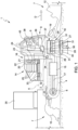
Figure 1 is a side elevation view, with parts removed for greater clarity and schematic parts, of a crawler vehicle according to the invention; -
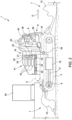
Figure 2 is a side elevation view, with parts removed for greater clarity and schematic parts, of a further embodiment of the crawler vehicle ofFigure 1 ; -
Figure 3 is a view from the top, with parts removed for greater clarity and schematic parts, of the crawler vehicle ofFigure 1 ; -
Figures 4 and5 are side elevation views, with parts removed for greater clarity and schematic parts, of the crawler vehicle ofFigure 1 in respective operating configurations; and -
Figure 6 is a side elevation view, with parts removed for greater clarity and schematic parts, of a variant of the crawler vehicle ofFigure 1 in a respective operating configuration. - With reference to
Figure 1 ,number 1 indicates, as a whole, a crawler vehicle for preparing ski runs. - In particular, the
crawler vehicle 1 is a snow groomer. - More in detail, the
crawler vehicle 1 is used for the preparation of ski runs for Alpine skiing and/or ski runs for cross-country skiing and/or ramps for ski jumping and/or half-pipes and/or snow-parks. - It should be pointed out that, according to a further embodiment, the
crawler vehicle 1 can be used in agricultural operations, such as for example the harvesting and/or the handling of agricultural products and/or the ensilage of fodder and/or the harvesting and/or the handling of bagasse. - Furthermore, the
crawler vehicle 1 can comprise a mulcher arranged on the front side of thecrawler vehicle 1 and can be used to mulch plants. - The
crawler vehicle 1 comprises aframe 2; a track 3 (Figure 3 ); atrack 4; a drive wheel 5 (Figure 3 ) and adrive wheel 6 independent of one another and coupled to the track 3 (Figure 3 ) and to thetrack 4, respectively, in order to operate the track 3 (Figure 3 ) and thetrack 4, respectively; a plurality of hydraulically operatedtools 7 connected to theframe 2; acabin 8 mounted on theframe 2; and auser interface 9 arranged inside thecabin 8. - In the specific non-limiting case of the invention shown and discussed herein, the
tools 7 comprise atiller 10, which is connected to theframe 2 in a movable manner and is operated by a hydraulic motor 11 (Figure 3 ), and ashovel 12, which is connected to theframe 2 in a movable manner and is operated by a hydraulic motor 13 (Figure 3 ). - For the purposes of this disclosure, the term "hydraulic motor" indicates any device for the conversion of hydraulic power into mechanical power and encloses, in its meaning, any type of hydraulic actuator and hydraulic cylinder.
- According to a non-limiting embodiment of the invention, the
cabin 8 is arranged in the front part of thecrawler vehicle 1 and faces theshovel 12 in a travelling direction D. - The
crawler vehicle 1 comprises anenergy storage assembly 14 configured to be removed from thecrawler vehicle 1 and to be replaced by a furtherenergy storage assembly 14; apropulsion system 15 configured to be powered by theenergy storage system 14; aconnection interface 16 configured to selectively and quickly connect/disconnect theenergy storage assembly 14 to/from thepropulsion system 15; and atransmission assembly 17 configured to transmit power from thepropulsion system 15 to thedrive wheels hydraulic motors 11 and 13 (Figure 3 ). - In particular, the
connection interface 16 is arranged behind thecabin 8 with respect to the travelling direction D of thecrawler vehicle 1. More in detail, theconnection interface 16 is fixed on theframe 2 behind thecabin 8. - Furthermore, the
crawler vehicle 1 comprises anenergy storage assembly 18, which is configured to be removed from thecrawler vehicle 1 and to be replaced by a furtherenergy storage assembly 18, and aconnection interface 19, which is preferably arranged under thecabin 8 and is configured to selectively connect/disconnect theenergy storage assembly 18 to/from thepropulsion system 15 in a quick manner. - In particular, the
connection interface 19 is fixed on theframe 2 under thecabin 8. - According to an alternative embodiment, which is not shown in the appended Figures, the
crawler vehicle 1 only comprise theenergy storage assembly 14 and theconnection interface 16 and lacks theenergy storage assembly 18 and theconnection interface 19. - According to a further alternative embodiment, which is not shown in the appended Figures, the
crawler vehicle 1 only comprise theenergy storage assembly 18 and theconnection interface 19 and lacks theenergy storage assembly 14 and theconnection interface 16. - With reference to
Figure 1 , theenergy storage assembly 14 comprises asupport element 20, which is provided with amechanical connector 21 and with apower connector 22 to be coupled to theconnection interface 16. - The
connection interface 16 comprises amechanical connector 23 configured to engage, in a releasable manner, themechanical connector 21 of theenergy storage assembly 14 and apower connector 24 configured to be connected to thepower connector 22 of theenergy storage assembly 14 so as to transmit power to thepropulsion system 15. - In the embodiment described and shown herein, the
energy storage assembly 14 comprises at least onebattery 25 for storing electrical energy. In particular, theenergy storage assembly 14 comprises a plurality ofbatteries 25 fixed to thesupport element 20. In said embodiment, thepropulsion system 15 comprises an electric motor. - In particular, the
energy storage assembly 18 comprises asupport element 26, which is provided with amechanical connector 27 and with apower connector 28 to be coupled to theconnection interface 19. - The
connection interface 19 comprises amechanical connector 29 configured to engage, in a releasable manner, themechanical connector 27 of theenergy storage assembly 18 and apower connector 30 configured to be connected to thepower connector 28 of theenergy storage assembly 18 so as to transmit power to thepropulsion system 15. - In the embodiment described and shown herein, the
energy storage assembly 18 also comprises at least onebattery 31 for storing electrical energy. In particular, theenergy storage assembly 18 comprises a plurality ofbatteries 31 fixed to thesupport element 26. - In particular, the
power connectors power connectors propulsion system 15. - More in detail, the
mechanical connectors mechanical connectors - The number and the arrangement of the
mechanical connectors power connectors - According to an embodiment, the
connection interface 16 comprises at least oneguide 32. Theenergy storage assembly 14 comprises at least one slidingelement 33, which is configured to slide along therespective guide 32 so as to connect/disconnect theenergy storage assembly 14 to/from theconnection interface 16. - In particular, the
connection interface 16 comprises twoguides 32, each extending along a respective longitudinal axis A substantially parallel to the travelling direction D. - Furthermore, the
crawler vehicle 1 comprises aposition sensor assembly 34 configured to detect the relative position of theconnection interface 16 and/or of theconnection interface 19 with respect to arespective replacement device energy storage assembly connection interface energy storage assembly energy storage assembly position sensor assembly 34 comprises a lidar and/or a radar and/or a video camera and/or a GPS sensor. - The
crawler vehicle 1 further comprises acontrol unit 37, which is in communication with theposition sensor assembly 34 and is configured to control the position of thecrawler vehicle 1 relative to thereplacement device 35 or to thereplacement device 36 depending on the relative position detected by thesensor assembly 34. - In addition or alternatively, the
user interface 9 comprises anindicator 38 configured to emit a signal indicative of the relative position detected by theposition sensor assembly 34. - Furthermore, the
control assembly 37 comprises acharge sensor 39 configured to acquire the level of charge of theenergy storage assemblies 14 and/or 18. Theuser interface 9 comprises anindicator 40 configured to emit a signal indicative of the level of charge acquired by thecharge sensor 39. - In the specific case disclosed and shown in
Figure 1 , theuser interface 9 is a graphic interface, such as for example a screen, configured to display theindicators crawler vehicle 1. - According to an embodiment, the
replacement device 35 can comprise an automated equipment, such as for example a manipulator, or a crane. Thereplacement device 36 can comprise an automatic apparatus that can selectively be lifted/lowered from/to the ground. -
Figure 2 shown a further embodiment of the invention, in which thecrawler vehicle 1 is not provided with theenergy storage assembly 18 and with theconnection interface 19 and comprises anenergy storage assembly 41 provided with at least onetank 42 to contain hydrogen (H2). - In particular, the
energy storage assembly 41 comprises a plurality oftanks 42 fixed to thesupport element 20. - According to said embodiment, the
propulsion system 15 comprises a hydrogen motor. - With reference to
Figure 3 , thetransmission assembly 17 comprises ahydraulic system 43, which is powered by thepropulsion system 15 and is configured to transmit power to thedrive wheels hydraulic motors hydraulic system 43 comprises a plurality of pumps. - In use and with reference to
Figure 4 , when theenergy storage assembly 14 is substantially discharged, thecrawler vehicle 1 is led to a replacement area, where thereplacement device 35 is located so as to remove and replace theenergy storage assembly 14. - The
position sensor assembly 34 detects the relative position of theconnection interface 16 with respect to thereplacement device 35 and thecontrol unit 37 controls the position of thecrawler vehicle 1 with respect to thereplacement device 35 as a function of the relative position detected by theposition sensor assembly 34. - Alternatively or in addition, the
indicator 38 of theuser interface 9 emits a signal indicative of the relative position detected by theposition sensor assembly 34 so as to allow the operator of thecrawler vehicle 1 to check for the correct positioning of theconnection interface 16. - Once the
connection interface 16 is correctly positioned, thereplacement device 35 starts the sliding of the dischargedenergy storage assembly 14 along theguides 32 so as to disconnect themechanical connectors power connectors energy storage assembly 14 from theconnection interface 16. - Once the discharged
energy storage system 14 has been removed, thereplacement device 35 connects a further chargedenergy storage assembly 14 to theconnection interface 16. - In particular, during the connection step, the
replacement device 35 starts the sliding of the further chargedenergy storage assembly 14 along theguides 32, until themechanical connectors power connectors - With reference to
Figure 5 , when theenergy storage assembly 18 is substantially discharged, thecrawler vehicle 1 is led to a replacement area, where thereplacement device 36 is located so as to remove and replace theenergy storage assembly 18. - Once the
connection interface 19 is correctly positioned above thereplacement device 36, thereplacement device 36 is lifted from the ground until it engages theenergy storage assembly 18. - At this point, the
replacement device 36 is moved downwards so as to disconnect themechanical connectors power connectors energy storage assembly 18 from under thecabin 8. - Once the discharged
energy storage system 18 has been removed, thereplacement device 36 connects a further chargedenergy storage assembly 18 to theconnection interface 19. - In particular, during the connection step, said further charged
energy storage system 18 is coupled to an upper end of thereplacement device 36, which is lifted again from the ground until themechanical connectors power connectors -
Figure 6 shows a variant of the invention, in which thecrawler vehicle 1 comprises anenergy storage assembly 44, which is is not provided with sliding elements, and aconnection interface 45, which is not provided with guides. - In use and according to said variant, when the
energy storage assembly 44 is substantially discharged, thecrawler vehicle 1 is led to a replacement area, where areplacement device 46 is located so as to remove and replace theenergy storage assembly 44. - In particular, the
replacement device 46 comprises alifting system 47, such as for example a crane, configured to vertically lift and lower theenergy storage assembly 44 relative to theconnection interface 45. - Once the
connection interface 45 is correctly positioned relative to thereplacement device 46, thelifting system 47 is connected to theenergy storage assembly 44. - At this point, the
lifting system 47 is operated so as to lift the dischargedenergy storage assembly 44 relative to theconnection interface 45, thus disconnecting themechanical connectors power connectors - Once the discharged
energy storage assembly 44 has been removed, thelifting system 47 lowers a further chargedenergy storage assembly 44 onto theconnection interface 45 so as to connect said further chargedenergy storage assembly 44 to thepropulsion system 15. - The invention can evidently be subjected to variants, though without going beyond the scope of protection set forth in the appended claims.
Claims (14)
- A crawler vehicle, preferably for preparing ski runs, the crawler vehicle (1) comprising:- a frame (2);- a first energy storage assembly (14; 41; 44) configured to be removed from the crawler vehicle (1) and to be replaced with a further first energy storage assembly (14; 41; 44)- a propulsion system (15) configured to be powered by the first energy storage assembly (14; 41; 44);- a connection interface (16; 45) configured to selectively connect/disconnect rapidly the first energy storage assembly (14; 41; 44) to/from the propulsion system (15) ;- a first motorised track (3) and a second motorised track (4); and- a transmission assembly (17) configured to transmit power from the propulsion system (15) to the first and to the second track (3, 4).
- The crawler vehicle as claimed in claim 1, wherein the first energy storage assembly (14; 41; 44) comprises a first mechanical connector (21) and a first power connector (22); the connection interface (16; 45) comprising a second mechanical connector (23) configured to releasably engage the first mechanical connector (21) and a second power connector (24) configured to be connected to the first power connector (22) so as to transmit power to the propulsion system (15).
- The crawler vehicle as claimed in claim 2, wherein the first energy storage assembly (14; 41; 44) comprises a support element (20), which is provided with the first mechanical connector (21) and with the first power connector (22) for coupling with the connection interface (16; 45).
- The crawler vehicle as claimed in any one of the foregoing claims, and comprising a cabin (8) mounted on the frame (2), the connection interface (16; 45) being arranged behind the cabin (8) with respect to a travelling direction (D) of the crawler vehicle (1).
- The crawler vehicle as claimed in claim 4, wherein the connection interface (16) comprises at least one guide (32); the first energy storage assembly (14; 41) comprising at least one sliding element (33), which is configured to slide along the respective guide (32) so as to connect/disconnect the first energy storage assembly (14; 41) to/from the connection interface (16).
- The crawler vehicle as claimed in any one of the foregoing claims, and comprising a position sensor assembly (34) configured to detect the relative position of the connection interface (16; 45) with respect to a replacement device (35; 36; 46) of the first energy storage assembly (14; 41; 44), preferably the position sensor assembly (34) comprising a lidar and/or a radar and/or a video camera and/or a GPS sensor.
- The crawler vehicle as claimed in any one of the foregoing claims, and comprising a second energy storage assembly (18) configured to be removed from the crawler vehicle (1) and be replaced with a further second energy storage assembly (18), and a further connection interface (19), which is preferably arranged under the cabin (8) and is configured to selectively connect/disconnect the second energy storage assembly (18) to/from the propulsion system (15) in a rapid manner.
- The crawler vehicle as claimed in any one of the foregoing claims, wherein each energy storage assembly (14; 18; 41; 44) comprises at least one battery (25; 31) for storing electrical energy or at least one tank (42) for storing hydrogen.
- A method for managing the operation of a crawler vehicle, preferably for preparing ski runs, the method comprising the steps of:- powering a propulsion system (15) of the crawler vehicle (1) by means of an energy storage assembly (14; 18; 41; 44);- transmitting power from the propulsion system (15) to a first and a second track (3, 4) of the crawler vehicle (1) ;- removing the energy storage assembly (14; 18; 41; 44) from the tracked vehicle (1); and- replacing the removed energy storage assembly (14; 18; 41; 44) with a further energy storage assembly (14; 18; 41; 44) .
- The method as claimed in claim 9, wherein the removed energy storage assembly (14; 18; 41; 44) is less loaded than the further energy storage assembly (14; 18; 41; 44).
- The method as claimed in claim 9 or 10, and comprising the step of selectively connecting/disconnecting rapidly the energy storage assembly (14; 18; 41; 44) to/from the propulsion system (15) by means of a connection interface (16; 19; 45).
- The method as claimed in claim 11, wherein the step of selectively connecting/disconnecting rapidly the energy storage assembly (14; 41) to/from the propulsion system (15) comprises implementing a sliding of the energy storage assembly (14; 41) with respect to the connection interface (16).
- The method as claimed in claim 11, wherein the step of selectively connecting/disconnecting rapidly the energy storage assembly (44) to/from the propulsion system (15) comprises lifting the energy storage assembly (44) from the connection interface (45).
- The method as claimed in claim 11, wherein the step of selectively connecting/disconnecting rapidly the energy storage assembly (18) to/from the propulsion system (15) comprises removing the energy storage assembly (18) from under the cabin (8).
Applications Claiming Priority (1)
| Application Number | Priority Date | Filing Date | Title |
|---|---|---|---|
| IT102022000024399A IT202200024399A1 (en) | 2022-11-25 | 2022-11-25 | TRACKED VEHICLE AND METHOD OF MANAGING THE OPERATION OF SAID TRACKED VEHICLE |
Publications (1)
| Publication Number | Publication Date |
|---|---|
| EP4375130A1 true EP4375130A1 (en) | 2024-05-29 |
Family
ID=85462347
Family Applications (1)
| Application Number | Title | Priority Date | Filing Date |
|---|---|---|---|
| EP23211922.2A Pending EP4375130A1 (en) | 2022-11-25 | 2023-11-24 | Crawler vehicle and method for managing the operation of said crawler vehicle |
Country Status (5)
| Country | Link |
|---|---|
| US (1) | US20240174121A1 (en) |
| EP (1) | EP4375130A1 (en) |
| CN (1) | CN118082993A (en) |
| CA (1) | CA3220633A1 (en) |
| IT (1) | IT202200024399A1 (en) |
Citations (3)
| Publication number | Priority date | Publication date | Assignee | Title |
|---|---|---|---|---|
| WO2021245621A1 (en) * | 2020-06-05 | 2021-12-09 | Prinoth S.P.A. | Crawler vehicle, control method and computer program of said vehicle |
| US11407298B1 (en) * | 2021-11-15 | 2022-08-09 | Amos Power, Inc. | Removable battery unit for an electric vehicle |
| CN115179908A (en) * | 2022-09-06 | 2022-10-14 | 徐工集团工程机械股份有限公司建设机械分公司 | Trade trolley |
Family Cites Families (4)
| Publication number | Priority date | Publication date | Assignee | Title |
|---|---|---|---|---|
| EP2112963B1 (en) * | 2006-10-06 | 2018-05-30 | iRobot Defense Holdings, Inc. | Robotic vehicle with tracks and flippers |
| US8413752B2 (en) * | 2006-10-06 | 2013-04-09 | Irobot Corporation | Robotic vehicle |
| IT202100030644A1 (en) * | 2021-12-03 | 2023-06-03 | Soilmec Spa | FOUNDATION MACHINE EQUIPPED WITH AN INTERCHANGEABLE ELECTRIC STORAGE SYSTEM AND HANDLING EQUIPMENT FOR THE STORAGE SYSTEM |
| US11364959B1 (en) * | 2021-12-27 | 2022-06-21 | Amos Power, Inc. | Modular robotic vehicle |
-
2022
- 2022-11-25 IT IT102022000024399A patent/IT202200024399A1/en unknown
-
2023
- 2023-11-21 CA CA3220633A patent/CA3220633A1/en active Pending
- 2023-11-21 US US18/515,498 patent/US20240174121A1/en active Pending
- 2023-11-24 EP EP23211922.2A patent/EP4375130A1/en active Pending
- 2023-11-24 CN CN202311589223.1A patent/CN118082993A/en active Pending
Patent Citations (3)
| Publication number | Priority date | Publication date | Assignee | Title |
|---|---|---|---|---|
| WO2021245621A1 (en) * | 2020-06-05 | 2021-12-09 | Prinoth S.P.A. | Crawler vehicle, control method and computer program of said vehicle |
| US11407298B1 (en) * | 2021-11-15 | 2022-08-09 | Amos Power, Inc. | Removable battery unit for an electric vehicle |
| CN115179908A (en) * | 2022-09-06 | 2022-10-14 | 徐工集团工程机械股份有限公司建设机械分公司 | Trade trolley |
Also Published As
| Publication number | Publication date |
|---|---|
| IT202200024399A1 (en) | 2024-05-25 |
| CA3220633A1 (en) | 2024-05-25 |
| US20240174121A1 (en) | 2024-05-30 |
| CN118082993A (en) | 2024-05-28 |
Similar Documents
| Publication | Publication Date | Title |
|---|---|---|
| KR102657656B1 (en) | Mounting and dismounting system for battery assemblies | |
| CN111741866B (en) | Method and system for mounting and dismounting battery in vehicle | |
| US11745576B2 (en) | Electric haul truck | |
| JP7448480B2 (en) | Alignment and locking mechanism for removable battery assembly | |
| EP3980286B1 (en) | Battery load mechanism for electric lhd mining machine | |
| US20120181981A1 (en) | Energy supply unit, land vehicle, replacement station and method for replacement of an energy supply unit contained in a land vehicle | |
| US20180041053A1 (en) | Device for Exchanging and Charging Batteries on Remote Controlled Hobby Vehicles | |
| CA2813018C (en) | A piggyback forklift truck and method of operating same | |
| US20230202288A1 (en) | Crawler vehicle, control method and computer program of said vehicle | |
| EP4375130A1 (en) | Crawler vehicle and method for managing the operation of said crawler vehicle | |
| EP2072421A1 (en) | System for driving hydraulic components of a vehicle superstructure | |
| US11890953B2 (en) | Electric accessory interface for work vehicle | |
| CN105539140B (en) | System and method for material transfer and transport | |
| EP4527673A1 (en) | Crawler vehicle and control method to control said crawler vehicle | |
| WO2025259432A1 (en) | Hydraulic load management for electric motor driven systems | |
| DE102021120667A1 (en) | Harvesting chain with transmission of electrical energy from a transport vehicle to a harvesting machine and method for its operation | |
| EA040335B1 (en) | BATTERY INSTALLATION AND REMOVAL SYSTEM FOR BATTERY ASSEMBLY | |
| EA040328B1 (en) | LEVELING AND LOCKING MECHANISM FOR REMOVABLE BATTERY ASSEMBLY | |
| HK1088289B (en) | Transportation vehicle for mining operation |
Legal Events
| Date | Code | Title | Description |
|---|---|---|---|
| PUAI | Public reference made under article 153(3) epc to a published international application that has entered the european phase |
Free format text: ORIGINAL CODE: 0009012 |
|
| STAA | Information on the status of an ep patent application or granted ep patent |
Free format text: STATUS: THE APPLICATION HAS BEEN PUBLISHED |
|
| AK | Designated contracting states |
Kind code of ref document: A1 Designated state(s): AL AT BE BG CH CY CZ DE DK EE ES FI FR GB GR HR HU IE IS IT LI LT LU LV MC ME MK MT NL NO PL PT RO RS SE SI SK SM TR |
|
| STAA | Information on the status of an ep patent application or granted ep patent |
Free format text: STATUS: REQUEST FOR EXAMINATION WAS MADE |
|
| 17P | Request for examination filed |
Effective date: 20241125 |
|
| RBV | Designated contracting states (corrected) |
Designated state(s): AL AT BE BG CH CY CZ DE DK EE ES FI FR GB GR HR HU IE IS IT LI LT LU LV MC ME MK MT NL NO PL PT RO RS SE SI SK SM TR |