EP4375079A1 - Transport device and recording device - Google Patents
Transport device and recording device Download PDFInfo
- Publication number
- EP4375079A1 EP4375079A1 EP23212662.3A EP23212662A EP4375079A1 EP 4375079 A1 EP4375079 A1 EP 4375079A1 EP 23212662 A EP23212662 A EP 23212662A EP 4375079 A1 EP4375079 A1 EP 4375079A1
- Authority
- EP
- European Patent Office
- Prior art keywords
- medium
- port
- section
- transport
- cover
- Prior art date
- Legal status (The legal status is an assumption and is not a legal conclusion. Google has not performed a legal analysis and makes no representation as to the accuracy of the status listed.)
- Granted
Links
Images

Classifications
-
- B—PERFORMING OPERATIONS; TRANSPORTING
- B41—PRINTING; LINING MACHINES; TYPEWRITERS; STAMPS
- B41J—TYPEWRITERS; SELECTIVE PRINTING MECHANISMS, i.e. MECHANISMS PRINTING OTHERWISE THAN FROM A FORME; CORRECTION OF TYPOGRAPHICAL ERRORS
- B41J29/00—Details of, or accessories for, typewriters or selective printing mechanisms not otherwise provided for
- B41J29/377—Cooling or ventilating arrangements
-
- B—PERFORMING OPERATIONS; TRANSPORTING
- B41—PRINTING; LINING MACHINES; TYPEWRITERS; STAMPS
- B41J—TYPEWRITERS; SELECTIVE PRINTING MECHANISMS, i.e. MECHANISMS PRINTING OTHERWISE THAN FROM A FORME; CORRECTION OF TYPOGRAPHICAL ERRORS
- B41J11/00—Devices or arrangements of selective printing mechanisms, e.g. ink-jet printers or thermal printers, for supporting or handling copy material in sheet or web form
- B41J11/0015—Devices or arrangements of selective printing mechanisms, e.g. ink-jet printers or thermal printers, for supporting or handling copy material in sheet or web form for treating before, during or after printing or for uniform coating or laminating the copy material before or after printing
-
- B—PERFORMING OPERATIONS; TRANSPORTING
- B41—PRINTING; LINING MACHINES; TYPEWRITERS; STAMPS
- B41J—TYPEWRITERS; SELECTIVE PRINTING MECHANISMS, i.e. MECHANISMS PRINTING OTHERWISE THAN FROM A FORME; CORRECTION OF TYPOGRAPHICAL ERRORS
- B41J11/00—Devices or arrangements of selective printing mechanisms, e.g. ink-jet printers or thermal printers, for supporting or handling copy material in sheet or web form
- B41J11/007—Conveyor belts or like feeding devices
-
- B—PERFORMING OPERATIONS; TRANSPORTING
- B41—PRINTING; LINING MACHINES; TYPEWRITERS; STAMPS
- B41J—TYPEWRITERS; SELECTIVE PRINTING MECHANISMS, i.e. MECHANISMS PRINTING OTHERWISE THAN FROM A FORME; CORRECTION OF TYPOGRAPHICAL ERRORS
- B41J15/00—Devices or arrangements of selective printing mechanisms, e.g. ink-jet printers or thermal printers, specially adapted for supporting or handling copy material in continuous form, e.g. webs
- B41J15/04—Supporting, feeding, or guiding devices; Mountings for web rolls or spindles
- B41J15/048—Conveyor belts or like feeding devices
-
- B—PERFORMING OPERATIONS; TRANSPORTING
- B41—PRINTING; LINING MACHINES; TYPEWRITERS; STAMPS
- B41J—TYPEWRITERS; SELECTIVE PRINTING MECHANISMS, i.e. MECHANISMS PRINTING OTHERWISE THAN FROM A FORME; CORRECTION OF TYPOGRAPHICAL ERRORS
- B41J29/00—Details of, or accessories for, typewriters or selective printing mechanisms not otherwise provided for
- B41J29/17—Cleaning arrangements
-
- B—PERFORMING OPERATIONS; TRANSPORTING
- B41—PRINTING; LINING MACHINES; TYPEWRITERS; STAMPS
- B41J—TYPEWRITERS; SELECTIVE PRINTING MECHANISMS, i.e. MECHANISMS PRINTING OTHERWISE THAN FROM A FORME; CORRECTION OF TYPOGRAPHICAL ERRORS
- B41J3/00—Typewriters or selective printing or marking mechanisms characterised by the purpose for which they are constructed
- B41J3/407—Typewriters or selective printing or marking mechanisms characterised by the purpose for which they are constructed for marking on special material
- B41J3/4078—Printing on textile
Definitions
- the present disclosure relates to a transport device and a recording device.
- JP-A-2022-7552 discloses a recording device including a recording section that performs recording on a medium, a transport belt that transports the medium, a pressing section that presses the medium against the transport belt, and a cover that covers the recording section and a pressing section.
- the pressing section presses the medium against the transport belt, so that the medium is attached to the transport belt.
- the pressing section may press the medium against the transport belt while heating the medium and then attach the medium to the transport belt.
- the heat may be conducted downstream in the transport direction. For example, if heat is conducted to the recording section, the recording quality may be impaired.
- a transport device that solves the above problem is a transport device that transports a medium to be recorded by a recording section, includes a transport belt for transporting the medium; a pressing section that is located further upstream in a transport direction of the medium than is the recording section and that presses the medium against the transport belt while heating the medium; a cover that covers the recording section and the pressing section and that has an intake port; and a fan that draws air into the cover through the intake port and that is located further upstream in the transport direction than is the intake port, wherein the intake port is located between the recording section and the pressing section in the transport direction.
- a recording device that solves the above problem includes a recording section that records to the medium; a transport belt for transporting the medium; a pressing section that is located further upstream in a transport direction of the medium than is the recording section and that presses the medium against the transport belt while heating the medium; a cover that covers the recording section and the pressing section and that has an intake port; and a fan that draws air into the cover through the intake port and that is located further upstream in the transport direction than is the intake port, wherein the intake port is located between the recording section and the pressing section in the transport direction.
- the recording device is, for example, an inkjet printer that records text, photographs or other images by ejecting ink, which is an example of a liquid, onto a medium such as paper or fabric.
- the recording device 11 is equipped with a recording section 12.
- the recording section 12 is configured to record to the medium 99.
- the recording section 12 records to the medium 99 by ejecting liquid onto the medium 99.
- Recording by the recording section 12 is not limited to liquid; for example, toner may be recorded on the medium 99 by spraying the toner onto the medium 99.
- the recording section 12 has a head 13.
- the head 13 has a nozzle surface 15 in which one or more nozzles 14 are opened.
- the nozzle surface 15 faces the medium 99.
- the head 13 ejects liquid from the nozzles 14 onto the medium 99.
- the recording section 12 has a carriage 16.
- the carriage 16 mounts the head 13.
- the carriage 16 scans the medium 99.
- the recording device 11 is a serial printer.
- the recording device 11 may be a line printer capable of ejecting liquid simultaneously across the width of the medium 99.
- the recording device 11 is equipped with a holding section 17.
- the holding section 17 holds the recording section 12.
- the holding section 17 is connected to the carriage 16.
- the holding section 17 guides the movement of the carriage 16.
- the holding section 17 includes, for example, a guide rail.
- the recording device 11 is equipped with a transport device 21.
- the transport device 21 transports the medium 99. Images are recorded on the medium 99 by the recording section 12 while the medium 99 is transported by the transport device 21.
- the transport device 21 is equipped with a transport section 22.
- the transport section 22 is configured to transport the medium 99.
- the transport section 22 has a first roller 23, a second roller 24, and a transport belt 25.
- the transport belt 25 is wound around the first roller 23 and the second roller 24.
- the transport belt 25 rotates along the first roller 23 and the second roller 24 as the first roller 23 and the second roller 24 rotate.
- the transport belt 25 rotates in the counterclockwise direction.
- the transport belt 25 transports the medium 99 in the transport direction Y by rotating.
- the transport belt 25 faces the recording section 12. Thus, an image is recorded on the medium 99 by the recording section 12 on the transport belt 25.
- the transport belt 25 has an inner circumferential surface 26 and an outer circumferential surface 27.
- the inner circumferential surface 26 is a surface that contacts the first roller 23 and the second roller 24.
- the outer circumferential surface 27 is a surface that contacts the medium 99.
- the outer circumferential surface 27 can be said to be a surface that supports the medium 99.
- the outer circumferential surface 27 faces the nozzle surface 15.
- the transport belt 25 is an adhesive belt to which the medium 99 is attached.
- An adhesive is applied to the outer circumferential surface 27.
- the medium 99 is attached to the outer circumferential surface 27. This allows the medium 99 to be transported in a stable posture.
- the transport device 21 may have a pull-off section that pulls the medium 99 away from the outer circumferential surface 27.
- the pull-ff section is, for example, a roller around which the medium 99 is wound.
- the transport section 22 may have one or more winding rollers.
- the transport section 22 has a first winding roller 28 and a second winding roller 29.
- the first winding roller 28 and the second winding roller 29 transport the medium 99 by rotating with the medium 99 being wound around them.
- the first winding roller 28 and the second winding roller 29 contact the medium 99 before the medium 99 is attached to the transport belt 25.
- the medium 99 contacts the first winding roller 28, the second winding roller 29, and the transport belt 25, in this order.
- the transport device 21 may be equipped with a support section 30.
- the support section 30 is located in a region surrounded by the transport belt 25.
- the support section 30 contacts the inner circumferential surface 26.
- the support section 30 supports the medium 99 over the transport belt 25.
- the support section 30 is positioned facing the recording section 12.
- the transport device 21 is equipped with a pressing section 31.
- the pressing section 31 is configured to press the medium 99 against the transport belt 25. Specifically, the pressing section 31 presses the medium 99 against the outer circumferential surface 27.
- the pressing section 31 attaches the medium 99 to the transport belt 25 by pressing the medium 99 onto the transport belt 25.
- the pressing section 31 is located further upstream than the recording section 12 in the transport direction Y. The pressing section 31 presses the medium 99 that has passed through the first winding roller 28 and the second winding roller 29 onto the transport belt 25.
- the pressing section 31 presses the medium 99 onto the transport belt 25 while heating it.
- the pressing section 31 is a heat roller. When the pressing section 31 heats the medium 99, the medium 99 is more likely to attach to the transport belt 25.
- the pressing section 31 may be configured to reciprocate in the transport direction Y.
- the pressing section 31, for example, reciprocates between the position shown by the solid line and the position shown by the two-dotted chain line in FIG. 1 .
- the pressing section 31 presses the medium 99 onto the transport belt 25 while reciprocating in the transport direction Y. This makes it easier for the medium 99 to stick to the transport belt 25 compared to when the pressing section 31 presses the medium 99 onto the transport belt 25 while the pressing section 31 is stationary.
- the transport device 21 is equipped with a cover 32.
- the cover 32 is configured to cover the recording section 12 and the pressing section 31.
- the cover 32 may cover other components in addition to the recording section 12 and the pressing section 31.
- the cover 32 defines a first space A1 and a second space A2.
- the first space A1 and the second space A2 are spaces inside the cover 32.
- the first space A1 and the second space A2 are connected inside the cover 32.
- the first space A1 is a space where the recording section 12 is located.
- the second space A2 is a space where the pressing section 31 is located.
- the cover 32 has a first cover member 33 and a second cover member 34.
- the first cover member 33 covers the recording section 12. In one example, the first cover member 33 covers the recording section 12 and the holding section 17.
- the first cover member 33 defines the first space A1.
- the second cover member 34 covers the pressing section 31.
- the second cover member 34 defines a second space A2.
- the second cover member 34 is located further upstream than the first cover member 33 in the transport direction Y.
- the second cover member 34 is attached to the first cover member 33.
- the second cover member 34 may be configured to open and close, i.e., displace, with respect to the first cover member 33.
- the second cover member 34 is attached to the first cover member 33 using a hinge 35. When the second cover member 34 opens, the user can access the pressing section 31.
- the cover 32 covers the recording section 12 and the pressing section 31 to protect the recording section 12 and the pressing section 31.
- the heat from the pressing section 31 can easily cause the inside of the cover 32 to become high temperature. If the temperature inside the cover 32 become too high, there is a possibility that the recording quality will be affected. For example, if the first space A1 becomes hot, there is a possibility that the liquid ejected by the head 13 will denature. For example, if the first space A1 and the second space A2 become hot, there is a possibility that the transport belt 25 will be deformed. For example, if the first space A1 becomes hot, there is a possibility that the support section 30 will be deformed. Therefore, it is desirable that the heat from the pressing section 31 be conducted as little as possible downstream in the transport direction Y. For example, heat from the pressing section 31 should be conducted as little as possible inside the first cover member 33.
- the cover 32 has an intake port 36.
- the intake port 36 is an opening in the cover 32 for intake of air from outside the cover 32, i.e., outside air. Outside air is drawn into cover 32 through the intake port 36 by a fan 51 (to be described later).
- the intake port 36 is located between the recording section 12 and the pressing section 31 in the transport direction Y. In detail, the intake port 36 is located further downstream than the pressing section 31 when the pressing section 31 is at its most downstream position in the transport direction Y, and further upstream than the recording section 12.
- the intake port 36 is opened in the second cover member 34.
- air is supplied to the second space A2 through the intake port 36. This reduces the possibility of high temperatures inside the cover 32 due to air being drawn into the cover 32 from the intake port 36. In particular, the possibility of high temperatures in the second space A2 is reduced.
- the intake port 36 opens in the top surface of the second cover member 34. In other words, the intake port 36 opens toward the vertical direction. Thus, through the intake port 36, air flows downward from outside the cover 32 to inside the cover 32. The air drawn in from the intake port 36 flows upstream in the transport direction Y by the fan 51 in the second space A2.
- the intake port 36 is composed of a plurality of through holes 37.
- the plurality of through holes 37 are so-called punch holes. This reduces the possibility of dust entering the cover 32 through the intake port 36.
- the configuration of the intake port 36 with a plurality of through holes 37 can limit the amount of intake air from the intake port 36. Thus, air can easily flow from the first space A1 to the second space A2 by the fan 51 which draws air into the second space A2 from the intake port 36. This makes it difficult for heat from the pressing section 31 to be conducted.
- the cover 32 has an exhaust port 38.
- the exhaust port 38 is an opening for exhausting air from inside the cover 32.
- the fan 51 exhausts air out of the cover 32 through the exhaust port 38.
- the exhaust port 38 is located further upstream than the intake port 36 in the transport direction Y.
- the exhaust port 38 opens in the second cover member 34. Thus, the air is exhausted from the second space A2 through the exhaust port 38.
- Air drawn in through the intake port 36 is exhausted through the exhaust port 38.
- the air drawn in through intake port 36 flows toward the exhaust port 38.
- the air drawn in through the intake port 36 flows toward the upstream in the transport direction Y in the cover 32. This makes it difficult for heat from the pressing section 31 to be conducted downstream in the transport direction Y.
- the air exhausted from the exhaust port 38 is blown onto the medium 99 before the medium 99 is pressed onto the transport belt 25.
- the exhaust port 38 opens toward the first winding roller 28.
- the air exhausted from the exhaust port 38 is blown onto a portion of the medium 99 wound around the first winding roller 28.
- air heated by the pressing section 31 is blown onto the medium 99, and then the medium 99 is preheated. This makes it easier for the medium 99 to stick to the transport belt 25.
- by blowing air heated by the pressing section 31 onto the medium 99 fluff, dust, and the other particles adhering to the medium 99 are removed. This improves recording quality.
- the cover 32 may have an intake duct 39.
- the intake duct 39 is a duct that connects to the intake port 36.
- the intake duct 39 has an internal space through which air can flow.
- the intake duct 39 is attached to the second cover member 34. Specifically, the intake duct 39 is attached to a surface of inner wall of the second cover member 34.
- the inner wall of the second cover member 34 forms part of the intake duct 39.
- the inner wall surface of the second cover member 34 is a wall surface of the second cover member 34 facing the media 99 or outer circumferential surface 27 when the second cover member 34 is covering the pressing section 31.
- the inner wall of the second cover member 34 is a wall opposite to the outer wall of the second cover member 34 that is in contact with the outside air. Air drawn in through the intake port 36 flows through the intake duct 39.
- the air intake duct 39 is located between the recording section 12 and the pressing section 31 in the transport direction Y.
- the intake duct 39 has an outflow port 40.
- the outflow port 40 may be composed of a plurality of through holes 37, similar to the intake port 36. Air is supplied to the second space A2 through the outflow port 40.
- the outflow port 40 opens toward upstream in the transport direction Y.
- the intake duct 39 changes the flow of air drawn in through the intake port 36.
- the outflow port 40 opens toward upstream in the transport direction Y.
- air can easily flow from the intake port 36 toward upstream in the transport direction Y.
- heat from the pressing section 31 is less likely to be conducted downstream in the transport direction Y.
- the intake duct 39 traps dust entering through the intake port 36. Therefore, the possibility of dust entering the cover 32 is reduced compared to a configuration in which dust is drawn directly into the cover 32 from the intake port 36.
- the cover 32 may have an exhaust duct 41.
- the exhaust duct 41 is a duct that connects to the exhaust port 38.
- the exhaust duct 41 like the intake duct 39, has an internal space through which air can flow.
- the exhaust duct 41 is attached to the second cover member 34. Specifically, the exhaust duct 41 is attached to the surface of the inner wall of the second cover member 34, similar to the intake duct 39.
- the inner wall of the second cover member 34 forms part of the exhaust duct 41.
- the exhaust duct 41 is located further upstream than the intake duct 39 in the transport direction Y.
- the exhaust duct 41 is located above the pressing section 31. In one example, the exhaust duct 41 is located directly above the pressing section 31 when the pressing section 31 is at its most upstream position in the transport direction Y.
- the exhaust duct 41 has an inflow port 42.
- the inflow port 42 may be composed of a plurality of through holes 37, similar to the intake port 36.
- air that flows into the portion covered by the second cover member 34 through intake port 36 and outflow port 40 further flows into the exhaust duct 41 through inflow port 42.
- the inflow port 42 opens toward the vertical direction.
- the inflow port 42 opens toward the pressing section 31.
- the air in the second space A2 flows into the exhaust duct 41 through the inflow port 42 while hitting the pressing section 31.
- the inflow port 42 is located above the pressing section 31. Specifically, the inflow port 42 is located above a region where the pressing section 31 moves. In one example, the inflow port 42 is located directly above the pressing section 31 when the pressing section 31 is at its most upstream position in the transport direction Y. This makes it easier for air drawn into the exhaust duct 41 through the inflow port 42 to hit the pressing section 31.
- the exhaust duct 41 extends from the inflow port 42 to the exhaust port 38 so that the duct becomes narrow. As a result, the air is blown out from the exhaust port 38 with strong force. This facilitates removal of fluff, dust, and the like from the medium 99.
- the cover 32 may have a supply port 43.
- the supply port 43 is an opening for supplying air into the cover 32. Through the supply port 43, air is supplied to the inside of the cover 32 by a supply fan 52 (to be described later).
- the supply port 43 is located further downstream than the intake port 36 in the transport direction Y. For example, the supply port 43 is opened in the first cover member 33. Through the supply port 43, air is supplied to the first space A1.
- the supply port 43 may be composed of a plurality of through holes 37, similar to the intake port 36.
- the cover 32 may have a collection port 44.
- the collection port 44 is an opening for exhausting air from inside the cover 32. Through the collection port 44, air is exhausted from inside the cover 32 by the collection fan 53 (to be described later).
- the collection port 44 is located further downstream than the supply port 43 in the transport direction Y. For example, the supply port 43 is opened in the first cover member 33. Thus, through the collection port 44, air is exhausted from the first space A1. In the first space A1, air supplied from the supply port 43 is exhausted through the collection port 44.
- the collection port 44 may be composed of a plurality of through holes 37, similar to the intake port 36.
- mist is exhausted together with air from the first space A1.
- mist stays inside the cover 32.
- mist tends to stay between the head 13 and the support section 30. If mist stays between the head 13 and the support section 30, the recording quality may be affected.
- the mist is exhausted outside of the cover 32 through the collection port 44.
- mist is exhausted together with air supplied from the supply port 43.
- the transport device 21 may be equipped with a filter that collects mist exhausted from the collection port 44.
- the cover 32 may have a supply duct 45.
- the supply duct 45 is a duct that connects to the supply port 43.
- the supply duct 45 is attached to the first cover member 33.
- the supply duct 45 is located, for example, further above than the recording section 12. Air supplied from the supply port 43 flows through the supply duct 45.
- the supply duct 45 has a blowout port 46. Through the blowout port 46, air is supplied inside the cover 32. Air is blown out from the blowout port 46 into the first space A1 by the supply fan 52. The supply duct 45 extends from the supply port 43 to the blowout port 46 so that the duct becomes narrow. As a result, the air is blown out from the blowout port 46 with strong force.
- the blowout port 46 opens toward the vertical direction.
- the blowout port 46 is located further above than the recording section 12.
- the blowout port 46 is located further upstream than the head 13 in the transport direction Y.
- the blowout port 46 blows air downward.
- the air blown out from the blowout port 46 hits the transport belt 25.
- the air blown out from the blowout port 46 is divided into air flowing downstream in the transport direction Y along the transport belt 25 and air flowing upstream in the transport direction Y along the transport belt 25.
- the intake port 36 limits the amount of air that is drawn in, so some of the air tends to flow upstream in the transport direction Y along the transport belt 25 by the fan 51.
- the air flowing downstream in the transport direction Y flows between the head 13 and the support section 30. This suppresses the retention of mist.
- the air flowing upstream in the transport direction Y flows from the first space A1 to the second space A2. This reduces the possibility of heat from the pressing section 31 being conducted into the first space A1.
- the cover 32 may have a collection duct 47.
- the collection duct 47 is a duct connects to the collection port 44.
- the collection duct 47 is attached to the first cover member 33.
- the collection duct 47 is located, for example, further above than the recording section 12.
- the collection duct 47 has a recovery port 48. Through the recovery port 48, mist flows into the collection duct 47 with air. The air and mist inflow into the collection duct 47 through the recovery port 48 by the collection fan 53. In the collection duct 47, the recovery port 48 opens toward the vertical direction. The recovery port 48 is located further downstream than the head 13 in the transport direction Y. This enables the air that passes between the head 13 and the support section 30 to flow efficiently toward the recovery port 48. Specifically, as shown by white arrows in the first space A1, air flows from the blowout port 46 toward the recovery port 48.
- the cover 32 may have a partition plate 49.
- the partition plate 49 is attached to the second cover member 34.
- the partition plate 49 is located between the pressing section 31 and the winding roller.
- the partition plate 49 reduces the possibility of the pressing section 31 being cooled more than necessary.
- the partition plate 49 also reduces the possibility of dust entering the second space A2.
- the transport device 21 is equipped with the fan 51.
- the fan 51 is located inside the cover 32. Specifically, the fan 51 is located further upstream than the intake port 36 in the transport direction Y. When the fan 51 is driven, air is drawn in through the intake port 36. Thus, heat from the pressing section 31 is less likely to be transferred downstream in the transport direction Y.
- the fan 51 is located further downstream than the exhaust port 38 in the transport direction Y. When the fan 51 is driven, air is exhausted from the exhaust port 38. Thus, fluff, dust, and the like adhering to the medium 99 are removed.
- the fan 51 is located in the exhaust duct 41. This effectively exhausts the air from the exhaust port 38.
- the fan 51 may be located in the intake duct 39, or may be attached to the second cover member 34.
- the transport device 21 may be equipped with the supply fan 52.
- the supply fan 52 is located in the cover 32.
- the supply fan 52 is located in the supply duct 45.
- the supply fan 52 is driven, air is supplied through the supply port 43 to the supply duct 45.
- the supply fan 52 is driven, air is blown out from the blowout port 46.
- the transport device 21 may be equipped with the collection fan 53.
- the collection fan 53 is located in the cover 32. Specifically, the collection fan 53 is located in the collection duct 47. When the collection fan 53 is driven, air and mist flow into the collection duct 47 through the recovery port 48. When the collection fan 53 is driven, the air and the mist are exhausted from the collection port 44.
Landscapes
- Accessory Devices And Overall Control Thereof (AREA)
- Ink Jet (AREA)
- General Physics & Mathematics (AREA)
- Physics & Mathematics (AREA)
- Atmospheric Sciences (AREA)
- Engineering & Computer Science (AREA)
- Life Sciences & Earth Sciences (AREA)
- Biodiversity & Conservation Biology (AREA)
- Ecology (AREA)
- Environmental & Geological Engineering (AREA)
- Environmental Sciences (AREA)
- Delivering By Means Of Belts And Rollers (AREA)
- Handling Of Sheets (AREA)
Abstract
Description
- The present application is based on, and claims priority from
JP Application Serial Number 2022-188956, filed November 28, 2022 - The present disclosure relates to a transport device and a recording device.
-
JP-A-2022-7552 - In such a recording device, the pressing section may press the medium against the transport belt while heating the medium and then attach the medium to the transport belt. However, when the pressing section heats the medium, the heat may be conducted downstream in the transport direction. For example, if heat is conducted to the recording section, the recording quality may be impaired.
- A transport device that solves the above problem is a transport device that transports a medium to be recorded by a recording section, includes a transport belt for transporting the medium; a pressing section that is located further upstream in a transport direction of the medium than is the recording section and that presses the medium against the transport belt while heating the medium; a cover that covers the recording section and the pressing section and that has an intake port; and a fan that draws air into the cover through the intake port and that is located further upstream in the transport direction than is the intake port, wherein the intake port is located between the recording section and the pressing section in the transport direction.
- A recording device that solves the above problem includes a recording section that records to the medium; a transport belt for transporting the medium; a pressing section that is located further upstream in a transport direction of the medium than is the recording section and that presses the medium against the transport belt while heating the medium; a cover that covers the recording section and the pressing section and that has an intake port; and a fan that draws air into the cover through the intake port and that is located further upstream in the transport direction than is the intake port, wherein the intake port is located between the recording section and the pressing section in the transport direction.
-
-
FIG. 1 is a side view showing an embodiment of a recording device including a transport device. -
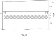
FIG. 2 is a plan view showing an intake port. - An example of a recording device equipped with a transport device will be described below with reference to figures. The recording device is, for example, an inkjet printer that records text, photographs or other images by ejecting ink, which is an example of a liquid, onto a medium such as paper or fabric.
- As shown in
FIG. 1 , therecording device 11 is equipped with arecording section 12. Therecording section 12 is configured to record to themedium 99. Therecording section 12 records to themedium 99 by ejecting liquid onto themedium 99. Recording by therecording section 12 is not limited to liquid; for example, toner may be recorded on themedium 99 by spraying the toner onto themedium 99. - The
recording section 12 has ahead 13. Thehead 13 has anozzle surface 15 in which one ormore nozzles 14 are opened. Thenozzle surface 15 faces themedium 99. Thehead 13 ejects liquid from thenozzles 14 onto themedium 99. - The
recording section 12 has acarriage 16. Thecarriage 16 mounts thehead 13. Thecarriage 16 scans themedium 99. Therecording device 11 is a serial printer. Therecording device 11 may be a line printer capable of ejecting liquid simultaneously across the width of themedium 99. - The
recording device 11 is equipped with aholding section 17. Theholding section 17 holds therecording section 12. Theholding section 17 is connected to thecarriage 16. Theholding section 17 guides the movement of thecarriage 16. Theholding section 17 includes, for example, a guide rail. - The
recording device 11 is equipped with atransport device 21. Thetransport device 21 transports themedium 99. Images are recorded on themedium 99 by therecording section 12 while themedium 99 is transported by thetransport device 21. - Next, the
transport device 21 will be described. Thetransport device 21 is equipped with atransport section 22. Thetransport section 22 is configured to transport themedium 99. Thetransport section 22 has afirst roller 23, asecond roller 24, and atransport belt 25. Thetransport belt 25 is wound around thefirst roller 23 and thesecond roller 24. Thetransport belt 25 rotates along thefirst roller 23 and thesecond roller 24 as thefirst roller 23 and thesecond roller 24 rotate. InFIG. 1 , thetransport belt 25 rotates in the counterclockwise direction. Thetransport belt 25 transports themedium 99 in the transport direction Y by rotating. Thetransport belt 25 faces therecording section 12. Thus, an image is recorded on themedium 99 by therecording section 12 on thetransport belt 25. - The
transport belt 25 has an innercircumferential surface 26 and an outercircumferential surface 27. The innercircumferential surface 26 is a surface that contacts thefirst roller 23 and thesecond roller 24. The outercircumferential surface 27 is a surface that contacts themedium 99. Thus, the outercircumferential surface 27 can be said to be a surface that supports themedium 99. The outercircumferential surface 27 faces thenozzle surface 15. - The
transport belt 25 is an adhesive belt to which themedium 99 is attached. An adhesive is applied to the outercircumferential surface 27. Thus, themedium 99 is attached to the outercircumferential surface 27. This allows themedium 99 to be transported in a stable posture. After images are recorded by therecording section 12, themedium 99 is pulled off from the outercircumferential surface 27, for example, by being pulled by another device. Thetransport device 21 may have a pull-off section that pulls themedium 99 away from the outercircumferential surface 27. In this case, the pull-ff section is, for example, a roller around which themedium 99 is wound. - The
transport section 22 may have one or more winding rollers. In one example, thetransport section 22 has a first windingroller 28 and a second windingroller 29. The first windingroller 28 and the second windingroller 29 transport the medium 99 by rotating with the medium 99 being wound around them. The first windingroller 28 and the second windingroller 29 contact the medium 99 before the medium 99 is attached to thetransport belt 25. When the medium 99 is transported by thetransport section 22, the medium 99 contacts the first windingroller 28, the second windingroller 29, and thetransport belt 25, in this order. - The
transport device 21 may be equipped with asupport section 30. Thesupport section 30 is located in a region surrounded by thetransport belt 25. Thesupport section 30 contacts the innercircumferential surface 26. Thesupport section 30 supports the medium 99 over thetransport belt 25. Thesupport section 30 is positioned facing therecording section 12. Thus, the region of the medium 99 that is supported by thesupport section 30 is recorded by therecording section 12. This stabilizes the posture of the medium 99 when therecording section 12 records to the medium 99, thereby improving recording quality. - The
transport device 21 is equipped with apressing section 31. Thepressing section 31 is configured to press the medium 99 against thetransport belt 25. Specifically, thepressing section 31 presses the medium 99 against the outercircumferential surface 27. Thepressing section 31 attaches the medium 99 to thetransport belt 25 by pressing the medium 99 onto thetransport belt 25. Thepressing section 31 is located further upstream than therecording section 12 in the transport direction Y. Thepressing section 31 presses the medium 99 that has passed through the first windingroller 28 and the second windingroller 29 onto thetransport belt 25. - The
pressing section 31 presses the medium 99 onto thetransport belt 25 while heating it. In one example, thepressing section 31 is a heat roller. When thepressing section 31 heats the medium 99, the medium 99 is more likely to attach to thetransport belt 25. - The
pressing section 31 may be configured to reciprocate in the transport direction Y. Thepressing section 31, for example, reciprocates between the position shown by the solid line and the position shown by the two-dotted chain line inFIG. 1 . Thepressing section 31 presses the medium 99 onto thetransport belt 25 while reciprocating in the transport direction Y. This makes it easier for the medium 99 to stick to thetransport belt 25 compared to when thepressing section 31 presses the medium 99 onto thetransport belt 25 while thepressing section 31 is stationary. - The
transport device 21 is equipped with acover 32. Thecover 32 is configured to cover therecording section 12 and thepressing section 31. Thecover 32 may cover other components in addition to therecording section 12 and thepressing section 31. By covering therecording section 12 and thepressing section 31 with thecover 32, the possibility of dust from the air adhering to therecording section 12 and thepressing section 31, and the possibility of users accidentally touching therecording section 12 and thepressing section 31 are reduced. - The
cover 32 defines a first space A1 and a second space A2. The first space A1 and the second space A2 are spaces inside thecover 32. The first space A1 and the second space A2 are connected inside thecover 32. The first space A1 is a space where therecording section 12 is located. The second space A2 is a space where thepressing section 31 is located. - The
cover 32 has afirst cover member 33 and asecond cover member 34. Thefirst cover member 33 covers therecording section 12. In one example, thefirst cover member 33 covers therecording section 12 and the holdingsection 17. Thefirst cover member 33 defines the first space A1. Thesecond cover member 34 covers thepressing section 31. Thesecond cover member 34 defines a second space A2. - The
second cover member 34 is located further upstream than thefirst cover member 33 in the transport direction Y. Thesecond cover member 34 is attached to thefirst cover member 33. Thesecond cover member 34 may be configured to open and close, i.e., displace, with respect to thefirst cover member 33. In one example, thesecond cover member 34 is attached to thefirst cover member 33 using ahinge 35. When thesecond cover member 34 opens, the user can access thepressing section 31. - The
cover 32 covers therecording section 12 and thepressing section 31 to protect therecording section 12 and thepressing section 31. On the other hand, the heat from thepressing section 31 can easily cause the inside of thecover 32 to become high temperature. If the temperature inside thecover 32 become too high, there is a possibility that the recording quality will be affected. For example, if the first space A1 becomes hot, there is a possibility that the liquid ejected by thehead 13 will denature. For example, if the first space A1 and the second space A2 become hot, there is a possibility that thetransport belt 25 will be deformed. For example, if the first space A1 becomes hot, there is a possibility that thesupport section 30 will be deformed. Therefore, it is desirable that the heat from thepressing section 31 be conducted as little as possible downstream in the transport direction Y. For example, heat from thepressing section 31 should be conducted as little as possible inside thefirst cover member 33. - The
cover 32 has anintake port 36. Theintake port 36 is an opening in thecover 32 for intake of air from outside thecover 32, i.e., outside air. Outside air is drawn intocover 32 through theintake port 36 by a fan 51 (to be described later). Theintake port 36 is located between therecording section 12 and thepressing section 31 in the transport direction Y. In detail, theintake port 36 is located further downstream than thepressing section 31 when thepressing section 31 is at its most downstream position in the transport direction Y, and further upstream than therecording section 12. Theintake port 36 is opened in thesecond cover member 34. Thus, air is supplied to the second space A2 through theintake port 36. This reduces the possibility of high temperatures inside thecover 32 due to air being drawn into thecover 32 from theintake port 36. In particular, the possibility of high temperatures in the second space A2 is reduced. - The
intake port 36 opens in the top surface of thesecond cover member 34. In other words, theintake port 36 opens toward the vertical direction. Thus, through theintake port 36, air flows downward from outside thecover 32 to inside thecover 32. The air drawn in from theintake port 36 flows upstream in the transport direction Y by thefan 51 in the second space A2. - As shown in
FIG. 2 , theintake port 36 is composed of a plurality of throughholes 37. The plurality of throughholes 37 are so-called punch holes. This reduces the possibility of dust entering thecover 32 through theintake port 36. Further, the configuration of theintake port 36 with a plurality of throughholes 37 can limit the amount of intake air from theintake port 36. Thus, air can easily flow from the first space A1 to the second space A2 by thefan 51 which draws air into the second space A2 from theintake port 36. This makes it difficult for heat from thepressing section 31 to be conducted. - As shown in
FIG. 1 , thecover 32 has anexhaust port 38. Theexhaust port 38 is an opening for exhausting air from inside thecover 32. Thefan 51 exhausts air out of thecover 32 through theexhaust port 38. Theexhaust port 38 is located further upstream than theintake port 36 in the transport direction Y. Theexhaust port 38 opens in thesecond cover member 34. Thus, the air is exhausted from the second space A2 through theexhaust port 38. - Air drawn in through the
intake port 36 is exhausted through theexhaust port 38. The air drawn in throughintake port 36 flows toward theexhaust port 38. In other word, the air drawn in through theintake port 36 flows toward the upstream in the transport direction Y in thecover 32. This makes it difficult for heat from thepressing section 31 to be conducted downstream in the transport direction Y. - The air exhausted from the
exhaust port 38 is blown onto the medium 99 before the medium 99 is pressed onto thetransport belt 25. Specifically, theexhaust port 38 opens toward the first windingroller 28. The air exhausted from theexhaust port 38 is blown onto a portion of the medium 99 wound around the first windingroller 28. Thus, air heated by thepressing section 31 is blown onto the medium 99, and then the medium 99 is preheated. This makes it easier for the medium 99 to stick to thetransport belt 25. In addition, by blowing air heated by thepressing section 31 onto the medium 99, fluff, dust, and the other particles adhering to the medium 99 are removed. This improves recording quality. - The
cover 32 may have an intake duct 39. The intake duct 39 is a duct that connects to theintake port 36. The intake duct 39 has an internal space through which air can flow. The intake duct 39 is attached to thesecond cover member 34. Specifically, the intake duct 39 is attached to a surface of inner wall of thesecond cover member 34. The inner wall of thesecond cover member 34 forms part of the intake duct 39. The inner wall surface of thesecond cover member 34 is a wall surface of thesecond cover member 34 facing themedia 99 or outercircumferential surface 27 when thesecond cover member 34 is covering thepressing section 31. The inner wall of thesecond cover member 34 is a wall opposite to the outer wall of thesecond cover member 34 that is in contact with the outside air. Air drawn in through theintake port 36 flows through the intake duct 39. The air intake duct 39 is located between therecording section 12 and thepressing section 31 in the transport direction Y. - The intake duct 39 has an
outflow port 40. Theoutflow port 40 may be composed of a plurality of throughholes 37, similar to theintake port 36. Air is supplied to the second space A2 through theoutflow port 40. In the intake duct 39, theoutflow port 40 opens toward upstream in the transport direction Y. Thus, the intake duct 39 changes the flow of air drawn in through theintake port 36. Theoutflow port 40 opens toward upstream in the transport direction Y. Thus, air can easily flow from theintake port 36 toward upstream in the transport direction Y. Thus, heat from thepressing section 31 is less likely to be conducted downstream in the transport direction Y. Further, the intake duct 39 traps dust entering through theintake port 36. Therefore, the possibility of dust entering thecover 32 is reduced compared to a configuration in which dust is drawn directly into thecover 32 from theintake port 36. - The
cover 32 may have anexhaust duct 41. Theexhaust duct 41 is a duct that connects to theexhaust port 38. Theexhaust duct 41, like the intake duct 39, has an internal space through which air can flow. Theexhaust duct 41 is attached to thesecond cover member 34. Specifically, theexhaust duct 41 is attached to the surface of the inner wall of thesecond cover member 34, similar to the intake duct 39. The inner wall of thesecond cover member 34 forms part of theexhaust duct 41. Theexhaust duct 41 is located further upstream than the intake duct 39 in the transport direction Y. Theexhaust duct 41 is located above thepressing section 31. In one example, theexhaust duct 41 is located directly above thepressing section 31 when thepressing section 31 is at its most upstream position in the transport direction Y. - The
exhaust duct 41 has aninflow port 42. Theinflow port 42 may be composed of a plurality of throughholes 37, similar to theintake port 36. Through theinflow port 42, air flows into theexhaust duct 41. Specifically, air that flows into the portion covered by thesecond cover member 34 throughintake port 36 andoutflow port 40 further flows into theexhaust duct 41 throughinflow port 42. In theexhaust duct 41, theinflow port 42 opens toward the vertical direction. In other words, in theexhaust duct 41, theinflow port 42 opens toward thepressing section 31. Thus, the air in the second space A2 flows into theexhaust duct 41 through theinflow port 42 while hitting thepressing section 31. For example, as shown by white arrows in the second space A2, air flows from theoutflow port 40 toward theinflow port 42. - The
inflow port 42 is located above thepressing section 31. Specifically, theinflow port 42 is located above a region where thepressing section 31 moves. In one example, theinflow port 42 is located directly above thepressing section 31 when thepressing section 31 is at its most upstream position in the transport direction Y. This makes it easier for air drawn into theexhaust duct 41 through theinflow port 42 to hit thepressing section 31. - The
exhaust duct 41 extends from theinflow port 42 to theexhaust port 38 so that the duct becomes narrow. As a result, the air is blown out from theexhaust port 38 with strong force. This facilitates removal of fluff, dust, and the like from the medium 99. - The
cover 32 may have asupply port 43. Thesupply port 43 is an opening for supplying air into thecover 32. Through thesupply port 43, air is supplied to the inside of thecover 32 by a supply fan 52 (to be described later). Thesupply port 43 is located further downstream than theintake port 36 in the transport direction Y. For example, thesupply port 43 is opened in thefirst cover member 33. Through thesupply port 43, air is supplied to the first space A1. Thesupply port 43 may be composed of a plurality of throughholes 37, similar to theintake port 36. - The
cover 32 may have acollection port 44. Thecollection port 44 is an opening for exhausting air from inside thecover 32. Through thecollection port 44, air is exhausted from inside thecover 32 by the collection fan 53 (to be described later). Thecollection port 44 is located further downstream than thesupply port 43 in the transport direction Y. For example, thesupply port 43 is opened in thefirst cover member 33. Thus, through thecollection port 44, air is exhausted from the first space A1. In the first space A1, air supplied from thesupply port 43 is exhausted through thecollection port 44. Thecollection port 44 may be composed of a plurality of throughholes 37, similar to theintake port 36. - From the
collection port 44, mist is exhausted together with air from the first space A1. When liquid is ejected from thehead 13, mist stays inside thecover 32. In particular, mist tends to stay between thehead 13 and thesupport section 30. If mist stays between thehead 13 and thesupport section 30, the recording quality may be affected. Thus, the mist is exhausted outside of thecover 32 through thecollection port 44. Through thecollection port 44, mist is exhausted together with air supplied from thesupply port 43. Thetransport device 21 may be equipped with a filter that collects mist exhausted from thecollection port 44. - The
cover 32 may have asupply duct 45. Thesupply duct 45 is a duct that connects to thesupply port 43. Thesupply duct 45 is attached to thefirst cover member 33. Thesupply duct 45 is located, for example, further above than therecording section 12. Air supplied from thesupply port 43 flows through thesupply duct 45. - The
supply duct 45 has ablowout port 46. Through theblowout port 46, air is supplied inside thecover 32. Air is blown out from theblowout port 46 into the first space A1 by thesupply fan 52. Thesupply duct 45 extends from thesupply port 43 to theblowout port 46 so that the duct becomes narrow. As a result, the air is blown out from theblowout port 46 with strong force. - In the
supply duct 45, theblowout port 46 opens toward the vertical direction. Theblowout port 46 is located further above than therecording section 12. Theblowout port 46 is located further upstream than thehead 13 in the transport direction Y. Theblowout port 46 blows air downward. The air blown out from theblowout port 46 hits thetransport belt 25. As a result, the air blown out from theblowout port 46 is divided into air flowing downstream in the transport direction Y along thetransport belt 25 and air flowing upstream in the transport direction Y along thetransport belt 25. As described above, theintake port 36 limits the amount of air that is drawn in, so some of the air tends to flow upstream in the transport direction Y along thetransport belt 25 by thefan 51. The air flowing downstream in the transport direction Y flows between thehead 13 and thesupport section 30. This suppresses the retention of mist. The air flowing upstream in the transport direction Y flows from the first space A1 to the second space A2. This reduces the possibility of heat from thepressing section 31 being conducted into the first space A1. - The
cover 32 may have acollection duct 47. Thecollection duct 47 is a duct connects to thecollection port 44. Thecollection duct 47 is attached to thefirst cover member 33. Thecollection duct 47 is located, for example, further above than therecording section 12. - The
collection duct 47 has arecovery port 48. Through therecovery port 48, mist flows into thecollection duct 47 with air. The air and mist inflow into thecollection duct 47 through therecovery port 48 by the collection fan 53. In thecollection duct 47, therecovery port 48 opens toward the vertical direction. Therecovery port 48 is located further downstream than thehead 13 in the transport direction Y. This enables the air that passes between thehead 13 and thesupport section 30 to flow efficiently toward therecovery port 48. Specifically, as shown by white arrows in the first space A1, air flows from theblowout port 46 toward therecovery port 48. - The
cover 32 may have apartition plate 49. Thepartition plate 49 is attached to thesecond cover member 34. Thepartition plate 49 is located between thepressing section 31 and the winding roller. Thepartition plate 49 reduces the possibility of thepressing section 31 being cooled more than necessary. Thepartition plate 49 also reduces the possibility of dust entering the second space A2. - The
transport device 21 is equipped with thefan 51. Thefan 51 is located inside thecover 32. Specifically, thefan 51 is located further upstream than theintake port 36 in the transport direction Y. When thefan 51 is driven, air is drawn in through theintake port 36. Thus, heat from thepressing section 31 is less likely to be transferred downstream in the transport direction Y. - The
fan 51 is located further downstream than theexhaust port 38 in the transport direction Y. When thefan 51 is driven, air is exhausted from theexhaust port 38. Thus, fluff, dust, and the like adhering to the medium 99 are removed. - The
fan 51 is located in theexhaust duct 41. This effectively exhausts the air from theexhaust port 38. Thefan 51 may be located in the intake duct 39, or may be attached to thesecond cover member 34. - The
transport device 21 may be equipped with thesupply fan 52. Thesupply fan 52 is located in thecover 32. In detail, thesupply fan 52 is located in thesupply duct 45. When thesupply fan 52 is driven, air is supplied through thesupply port 43 to thesupply duct 45. When thesupply fan 52 is driven, air is blown out from theblowout port 46. - The
transport device 21 may be equipped with the collection fan 53. The collection fan 53 is located in thecover 32. Specifically, the collection fan 53 is located in thecollection duct 47. When the collection fan 53 is driven, air and mist flow into thecollection duct 47 through therecovery port 48. When the collection fan 53 is driven, the air and the mist are exhausted from thecollection port 44. - Next, actions and effects of the above-described embodiment will be described.
- (1) The
fan 51 is located further upstream than theintake port 36 in the transport direction Y. Theintake port 36 is located between therecording section 12 and thepressing section 31 in the transport direction Y. According to the above configuration, the air that is drawn in from theintake port 36 flows upstream in the transport direction Y. Therefore, heat from thepressing section 31 is less likely to be conducted downstream in the transport direction Y. - (2) The
exhaust port 38 is located further upstream than thefan 51 in the transport direction Y. Thefan 51 exhausts air from the inside of thecover 32 through theexhaust port 38 and blows the air onto the medium 99 located further upstream in the transport direction Y than thepressing section 31. According to the above configuration, air heated by thepressing section 31 is blown onto the medium 99, and then the medium 99 is preheated. This makes it easier for the medium 99 to stick to thetransport belt 25. In addition, by blowing air onto the medium 99 by thefan 51, fluff, dust, and the other particles adhering to the medium 99 can be removed. This improves the recording quality by therecording section 12. - (3) The
exhaust duct 41 is located above thepressing section 31. Theinflow port 42 opens toward thepressing section 31. According to the above configuration, the air in thecover 32 flows into theexhaust duct 41 through theinflow port 42 while hitting thepressing section 31. This cools thepressing section 31. Therefore, possibility of heat from thepressing section 31 being conducted downstream in the transport direction Y is reduced. - (4) The
inflow port 42 is located above a region where thepressing section 31 moves. According to the above configuration, the air in thecover 32 flows into theexhaust duct 41 through theinflow port 42 while hitting thepressing section 31 that can move. This cools thepressing section 31. - (5) The air intake duct 39 is located between the
recording section 12 and thepressing section 31 in the transport direction Y. Theoutflow port 40 opens toward the upstream in the transport direction Y. According to the above configuration, the air drawn in from theintake port 36 flows out through theoutflow port 40 toward upstream in the transport direction Y. This reduces the possibility of heat from thepressing section 31 being conducted downstream in the transport direction Y. - The above embodiments may be modified as follows. The above embodiments and the following modifications can be implemented in combination with each other to the extent that there is no technical contradiction.
- The
pressing section 31 may be configured to displace between a position in contact with the medium 99 and a position separated from the medium 99. - The liquid ejected by the
head 13 is not limited to ink, but can also be, for example, a liquid in which particles of functional material are dispersed or mixed in the liquid. For example, thehead 13 may eject a liquid containing materials such as electrode or pixel materials in the form of dispersion or dissolution for use in the manufacture of liquid crystal displays, electroluminescence displays, and surface light emitting displays. - Hereinafter, technical ideas grasped from the above embodiments and modifications, and operations and effects thereof, will be described.
- A. A transport device is a transport device that transports a medium to be recorded by a recording section, includes a transport belt for transporting the medium; a pressing section that is located further upstream in a transport direction of the medium than is the recording section and that presses the medium against the transport belt while heating the medium; a cover that covers the recording section and the pressing section and that has an intake port; and a fan that draws air into the cover through the intake port and that is located further upstream in the transport direction than is the intake port, wherein the intake port is located between the recording section and the pressing section in the transport direction. According to the above configuration, the air drawn in from the intake port flows toward upstream in the transport direction. Therefore, heat from the pressing section is less likely to be conducted downstream in the transport direction Y.
- B. The above transport device may be configured such that the cover has an exhaust port, the exhaust port is located further upstream in the transport direction than is the fan, and the fan blows air onto the medium located further upstream than the pressing section in the transport direction and then exhausts the air from inside of the cover through the exhaust port. According to the above configuration, the air heated by the pressing section is blown onto the medium, and then the medium is preheated. This makes it easier for the medium 99 to stick to the
transport belt 25. - C. The above transport device may be configured such that the cover has an exhaust duct connecting to the exhaust port, the exhaust duct is located above the pressing section, the exhaust duct has an inflow port, and the inflow port is open toward the pressing section. According to the above configuration, the air in the cover flows into the exhaust duct through the inflow port while hitting the pressing section. This cools the pressing section. Therefore, the possibility of heat from the pressing section being conducted downstream in the transport direction is reduced.
- D. The above transport device may be configured such that the pressing section presses the medium against the transport belt while reciprocating in the transport direction and the inflow port is located above a region where the pressing section moves. According to the above configuration, the air in the cover flows into the exhaust duct through the inflow port while hitting the pressing section that can move. This cools the pressing section.
- E. The above transport device may be configured such that the cover has an intake duct connecting to the intake port, the intake duct is located between the recording section and the pressing section in the transport direction, the intake duct has an outflow port, and the outflow port is open toward upstream in the transport direction. According to the above configuration, the air drawn in from the intake port flows toward upstream in the transport direction through the outflow port. This reduces the possibility of heat from the pressing section being conducted downstream in the transport direction.
- F. A recording device includes a recording section that records to a medium; a transport belt for transporting the medium; a pressing section that is located further upstream in a transport direction of the medium than is the recording section and that presses the medium against the transport belt while heating the medium; a cover that covers the recording section and the pressing section and that has an intake port; and a fan that draws air into the cover through the intake port and that is located further upstream in the transport direction than is the intake port, wherein the intake port is located between the recording section and the pressing section in the transport direction. According to the above configuration, the same effects as the transport device described above can be obtained.
Claims (6)
- A transport device that transports a medium to be recorded by a recording section, the transport device comprising:a transport belt for transporting the medium;a pressing section that is located further upstream in a transport direction of the medium than is the recording section and that presses the medium against the transport belt while heating the medium;a cover that covers the recording section and the pressing section and that has an intake port; anda fan that draws air into the cover through the intake port and that is located further upstream in the transport direction than is the intake port, whereinthe intake port is located between the recording section and the pressing section in the transport direction.
- The transport device according to claim 1, whereinthe cover has an exhaust port,the exhaust port is located further upstream in the transport direction than is the fan, andthe fan blows air on the portion of the medium that is located upstream of the pressing section in the transport direction and then exhausts the air from inside of the cover through the exhaust port.
- The transport device according to claim 2, whereinthe cover has an exhaust duct connecting to the exhaust port,the exhaust duct is located above the pressing section,the exhaust duct has an inflow port, andthe inflow port opens toward the pressing section.
- The transport device according to claim 3, whereinthe pressing section presses the medium against the transport belt while reciprocating in the transport direction andthe inflow port is located above a region where the pressing section moves.
- The transport device according to claim 1, whereinthe cover has an intake duct connecting to the intake port,the intake duct is located between the recording section and the pressing section in the transport direction,the intake duct has an outflow port, andthe outflow port opens toward upstream in the transport direction.
- A recording device comprising:a recording section that records to a medium;a transport belt for transporting the medium;a pressing section that is located further upstream in a transport direction of the medium than is the recording section and that presses the medium against the transport belt while heating the medium;a cover that covers the recording section and the pressing section and that has an intake port; anda fan that draws air into the cover through the intake port and that is located further upstream in the transport direction than is the intake port, whereinthe intake port is located between the recording section and the pressing section in the transport direction.
Applications Claiming Priority (1)
| Application Number | Priority Date | Filing Date | Title |
|---|---|---|---|
| JP2022188956A JP2024077111A (en) | 2022-11-28 | 2022-11-28 | Conveying device and recording device |
Publications (2)
| Publication Number | Publication Date |
|---|---|
| EP4375079A1 true EP4375079A1 (en) | 2024-05-29 |
| EP4375079B1 EP4375079B1 (en) | 2025-03-19 |
Family
ID=88978181
Family Applications (1)
| Application Number | Title | Priority Date | Filing Date |
|---|---|---|---|
| EP23212662.3A Active EP4375079B1 (en) | 2022-11-28 | 2023-11-28 | Transport device and recording device |
Country Status (4)
| Country | Link |
|---|---|
| US (1) | US12420575B2 (en) |
| EP (1) | EP4375079B1 (en) |
| JP (1) | JP2024077111A (en) |
| CN (1) | CN118082391A (en) |
Citations (6)
| Publication number | Priority date | Publication date | Assignee | Title |
|---|---|---|---|---|
| CN204322762U (en) * | 2014-11-28 | 2015-05-13 | 杭州宏华数码科技股份有限公司 | The cloth pressing roller of the conduction band type inkjet printing machine with heater |
| EP3403833B1 (en) * | 2017-05-19 | 2020-11-18 | Seiko Epson Corporation | Printing apparatus |
| EP3842246A1 (en) * | 2019-12-26 | 2021-06-30 | Seiko Epson Corporation | Recording device with a blowing device |
| US20210283908A1 (en) * | 2020-03-10 | 2021-09-16 | Seiko Epson Corporation | Ink Jet Printing Recording Apparatus And Ink Jet Recording Method |
| JP2022007552A (en) | 2020-06-26 | 2022-01-13 | セイコーエプソン株式会社 | Recording device |
| JP2022188956A (en) | 2021-06-10 | 2022-12-22 | 日本製鉄株式会社 | Annular member and manufacturing method thereof |
Family Cites Families (1)
| Publication number | Priority date | Publication date | Assignee | Title |
|---|---|---|---|---|
| US20110199447A1 (en) * | 2010-02-17 | 2011-08-18 | Kabushiki Kaisha Toshiba | Image forming apparatus and drying method used in image forming apparatus |
-
2022
- 2022-11-28 JP JP2022188956A patent/JP2024077111A/en active Pending
-
2023
- 2023-11-27 US US18/520,154 patent/US12420575B2/en active Active
- 2023-11-27 CN CN202311602231.5A patent/CN118082391A/en active Pending
- 2023-11-28 EP EP23212662.3A patent/EP4375079B1/en active Active
Patent Citations (6)
| Publication number | Priority date | Publication date | Assignee | Title |
|---|---|---|---|---|
| CN204322762U (en) * | 2014-11-28 | 2015-05-13 | 杭州宏华数码科技股份有限公司 | The cloth pressing roller of the conduction band type inkjet printing machine with heater |
| EP3403833B1 (en) * | 2017-05-19 | 2020-11-18 | Seiko Epson Corporation | Printing apparatus |
| EP3842246A1 (en) * | 2019-12-26 | 2021-06-30 | Seiko Epson Corporation | Recording device with a blowing device |
| US20210283908A1 (en) * | 2020-03-10 | 2021-09-16 | Seiko Epson Corporation | Ink Jet Printing Recording Apparatus And Ink Jet Recording Method |
| JP2022007552A (en) | 2020-06-26 | 2022-01-13 | セイコーエプソン株式会社 | Recording device |
| JP2022188956A (en) | 2021-06-10 | 2022-12-22 | 日本製鉄株式会社 | Annular member and manufacturing method thereof |
Also Published As
| Publication number | Publication date |
|---|---|
| JP2024077111A (en) | 2024-06-07 |
| US20240176290A1 (en) | 2024-05-30 |
| US12420575B2 (en) | 2025-09-23 |
| EP4375079B1 (en) | 2025-03-19 |
| CN118082391A (en) | 2024-05-28 |
Similar Documents
| Publication | Publication Date | Title |
|---|---|---|
| JP7447490B2 (en) | recording device | |
| US8066368B2 (en) | Inkjet printer having a suction unit mounted on a cover of the printer | |
| JP5026155B2 (en) | Carriage unit and inkjet recording apparatus | |
| CN101746122B (en) | Recording device | |
| US8348415B2 (en) | Recording paper transportation path structure and printer | |
| US8960894B2 (en) | Inkjet recording apparatus with divided belt transport sections | |
| JP2009220499A (en) | Liquid discharge apparatus | |
| CN105593021A (en) | Ink-jet printer | |
| JP5311019B2 (en) | Recording device | |
| EP4375079A1 (en) | Transport device and recording device | |
| JP2000263814A (en) | Ink jet imaging apparatus | |
| US20100061788A1 (en) | Printer | |
| JP2025003153A (en) | Liquid ejection device | |
| US11065877B2 (en) | Drying device and inkjet printer therewith | |
| JP6604868B2 (en) | inkjet printer | |
| EP3403839B1 (en) | Carriage and liquid ejecting apparatus | |
| CN101389484A (en) | Drying Systems for Imaging Machines | |
| US12552182B2 (en) | Recording apparatus | |
| JP2004284058A (en) | Ink jet recorder | |
| JP4595953B2 (en) | Image forming apparatus | |
| US20250296375A1 (en) | Printing device | |
| JP2002178542A (en) | Ink jet recording device | |
| JP2025167013A (en) | Recording device | |
| JPS5964367A (en) | Apparatus for peeling paper in transfer type heat sensitive recording apparatus | |
| JP2004155027A (en) | Recording device |
Legal Events
| Date | Code | Title | Description |
|---|---|---|---|
| PUAI | Public reference made under article 153(3) epc to a published international application that has entered the european phase |
Free format text: ORIGINAL CODE: 0009012 |
|
| STAA | Information on the status of an ep patent application or granted ep patent |
Free format text: STATUS: THE APPLICATION HAS BEEN PUBLISHED |
|
| AK | Designated contracting states |
Kind code of ref document: A1 Designated state(s): AL AT BE BG CH CY CZ DE DK EE ES FI FR GB GR HR HU IE IS IT LI LT LU LV MC ME MK MT NL NO PL PT RO RS SE SI SK SM TR |
|
| STAA | Information on the status of an ep patent application or granted ep patent |
Free format text: STATUS: REQUEST FOR EXAMINATION WAS MADE |
|
| 17P | Request for examination filed |
Effective date: 20240906 |
|
| RBV | Designated contracting states (corrected) |
Designated state(s): AL AT BE BG CH CY CZ DE DK EE ES FI FR GB GR HR HU IE IS IT LI LT LU LV MC ME MK MT NL NO PL PT RO RS SE SI SK SM TR |
|
| GRAP | Despatch of communication of intention to grant a patent |
Free format text: ORIGINAL CODE: EPIDOSNIGR1 |
|
| RIC1 | Information provided on ipc code assigned before grant |
Ipc: B41J 11/00 20060101ALN20240924BHEP Ipc: B41J 3/407 20060101ALN20240924BHEP Ipc: B41J 29/17 20060101ALN20240924BHEP Ipc: B41J 15/04 20060101ALI20240924BHEP Ipc: B41J 29/377 20060101AFI20240924BHEP |
|
| STAA | Information on the status of an ep patent application or granted ep patent |
Free format text: STATUS: GRANT OF PATENT IS INTENDED |
|
| RIC1 | Information provided on ipc code assigned before grant |
Ipc: B41J 11/00 20060101ALN20241023BHEP Ipc: B41J 3/407 20060101ALN20241023BHEP Ipc: B41J 29/17 20060101ALN20241023BHEP Ipc: B41J 15/04 20060101ALI20241023BHEP Ipc: B41J 29/377 20060101AFI20241023BHEP |
|
| INTG | Intention to grant announced |
Effective date: 20241030 |
|
| GRAS | Grant fee paid |
Free format text: ORIGINAL CODE: EPIDOSNIGR3 |
|
| GRAA | (expected) grant |
Free format text: ORIGINAL CODE: 0009210 |
|
| STAA | Information on the status of an ep patent application or granted ep patent |
Free format text: STATUS: THE PATENT HAS BEEN GRANTED |
|
| AK | Designated contracting states |
Kind code of ref document: B1 Designated state(s): AL AT BE BG CH CY CZ DE DK EE ES FI FR GB GR HR HU IE IS IT LI LT LU LV MC ME MK MT NL NO PL PT RO RS SE SI SK SM TR |
|
| REG | Reference to a national code |
Ref country code: GB Ref legal event code: FG4D |
|
| REG | Reference to a national code |
Ref country code: CH Ref legal event code: EP |
|
| REG | Reference to a national code |
Ref country code: DE Ref legal event code: R096 Ref document number: 602023002501 Country of ref document: DE |
|
| REG | Reference to a national code |
Ref country code: IE Ref legal event code: FG4D |
|
| PG25 | Lapsed in a contracting state [announced via postgrant information from national office to epo] |
Ref country code: RS Free format text: LAPSE BECAUSE OF FAILURE TO SUBMIT A TRANSLATION OF THE DESCRIPTION OR TO PAY THE FEE WITHIN THE PRESCRIBED TIME-LIMIT Effective date: 20250619 |
|
| PG25 | Lapsed in a contracting state [announced via postgrant information from national office to epo] |
Ref country code: FI Free format text: LAPSE BECAUSE OF FAILURE TO SUBMIT A TRANSLATION OF THE DESCRIPTION OR TO PAY THE FEE WITHIN THE PRESCRIBED TIME-LIMIT Effective date: 20250319 |
|
| REG | Reference to a national code |
Ref country code: LT Ref legal event code: MG9D |
|
| PG25 | Lapsed in a contracting state [announced via postgrant information from national office to epo] |
Ref country code: NO Free format text: LAPSE BECAUSE OF FAILURE TO SUBMIT A TRANSLATION OF THE DESCRIPTION OR TO PAY THE FEE WITHIN THE PRESCRIBED TIME-LIMIT Effective date: 20250619 |
|
| PG25 | Lapsed in a contracting state [announced via postgrant information from national office to epo] |
Ref country code: HR Free format text: LAPSE BECAUSE OF FAILURE TO SUBMIT A TRANSLATION OF THE DESCRIPTION OR TO PAY THE FEE WITHIN THE PRESCRIBED TIME-LIMIT Effective date: 20250319 |
|
| PG25 | Lapsed in a contracting state [announced via postgrant information from national office to epo] |
Ref country code: LV Free format text: LAPSE BECAUSE OF FAILURE TO SUBMIT A TRANSLATION OF THE DESCRIPTION OR TO PAY THE FEE WITHIN THE PRESCRIBED TIME-LIMIT Effective date: 20250319 |
|
| PG25 | Lapsed in a contracting state [announced via postgrant information from national office to epo] |
Ref country code: BG Free format text: LAPSE BECAUSE OF FAILURE TO SUBMIT A TRANSLATION OF THE DESCRIPTION OR TO PAY THE FEE WITHIN THE PRESCRIBED TIME-LIMIT Effective date: 20250319 Ref country code: GR Free format text: LAPSE BECAUSE OF FAILURE TO SUBMIT A TRANSLATION OF THE DESCRIPTION OR TO PAY THE FEE WITHIN THE PRESCRIBED TIME-LIMIT Effective date: 20250620 |
|
| REG | Reference to a national code |
Ref country code: NL Ref legal event code: MP Effective date: 20250319 |
|
| PG25 | Lapsed in a contracting state [announced via postgrant information from national office to epo] |
Ref country code: NL Free format text: LAPSE BECAUSE OF FAILURE TO SUBMIT A TRANSLATION OF THE DESCRIPTION OR TO PAY THE FEE WITHIN THE PRESCRIBED TIME-LIMIT Effective date: 20250319 |
|
| PG25 | Lapsed in a contracting state [announced via postgrant information from national office to epo] |
Ref country code: SE Free format text: LAPSE BECAUSE OF FAILURE TO SUBMIT A TRANSLATION OF THE DESCRIPTION OR TO PAY THE FEE WITHIN THE PRESCRIBED TIME-LIMIT Effective date: 20250319 |
|
| PG25 | Lapsed in a contracting state [announced via postgrant information from national office to epo] |
Ref country code: SM Free format text: LAPSE BECAUSE OF FAILURE TO SUBMIT A TRANSLATION OF THE DESCRIPTION OR TO PAY THE FEE WITHIN THE PRESCRIBED TIME-LIMIT Effective date: 20250319 |
|
| PG25 | Lapsed in a contracting state [announced via postgrant information from national office to epo] |
Ref country code: ES Free format text: LAPSE BECAUSE OF FAILURE TO SUBMIT A TRANSLATION OF THE DESCRIPTION OR TO PAY THE FEE WITHIN THE PRESCRIBED TIME-LIMIT Effective date: 20250319 Ref country code: PT Free format text: LAPSE BECAUSE OF FAILURE TO SUBMIT A TRANSLATION OF THE DESCRIPTION OR TO PAY THE FEE WITHIN THE PRESCRIBED TIME-LIMIT Effective date: 20250721 |
|
| PG25 | Lapsed in a contracting state [announced via postgrant information from national office to epo] |
Ref country code: PL Free format text: LAPSE BECAUSE OF FAILURE TO SUBMIT A TRANSLATION OF THE DESCRIPTION OR TO PAY THE FEE WITHIN THE PRESCRIBED TIME-LIMIT Effective date: 20250319 |
|
| PG25 | Lapsed in a contracting state [announced via postgrant information from national office to epo] |
Ref country code: AT Free format text: LAPSE BECAUSE OF FAILURE TO SUBMIT A TRANSLATION OF THE DESCRIPTION OR TO PAY THE FEE WITHIN THE PRESCRIBED TIME-LIMIT Effective date: 20250319 |
|
| PG25 | Lapsed in a contracting state [announced via postgrant information from national office to epo] |
Ref country code: CZ Free format text: LAPSE BECAUSE OF FAILURE TO SUBMIT A TRANSLATION OF THE DESCRIPTION OR TO PAY THE FEE WITHIN THE PRESCRIBED TIME-LIMIT Effective date: 20250319 Ref country code: EE Free format text: LAPSE BECAUSE OF FAILURE TO SUBMIT A TRANSLATION OF THE DESCRIPTION OR TO PAY THE FEE WITHIN THE PRESCRIBED TIME-LIMIT Effective date: 20250319 |
|
| PG25 | Lapsed in a contracting state [announced via postgrant information from national office to epo] |
Ref country code: RO Free format text: LAPSE BECAUSE OF FAILURE TO SUBMIT A TRANSLATION OF THE DESCRIPTION OR TO PAY THE FEE WITHIN THE PRESCRIBED TIME-LIMIT Effective date: 20250319 |
|
| PG25 | Lapsed in a contracting state [announced via postgrant information from national office to epo] |
Ref country code: SK Free format text: LAPSE BECAUSE OF FAILURE TO SUBMIT A TRANSLATION OF THE DESCRIPTION OR TO PAY THE FEE WITHIN THE PRESCRIBED TIME-LIMIT Effective date: 20250319 |
|
| PG25 | Lapsed in a contracting state [announced via postgrant information from national office to epo] |
Ref country code: IS Free format text: LAPSE BECAUSE OF FAILURE TO SUBMIT A TRANSLATION OF THE DESCRIPTION OR TO PAY THE FEE WITHIN THE PRESCRIBED TIME-LIMIT Effective date: 20250719 |
|
| REG | Reference to a national code |
Ref country code: DE Ref legal event code: R097 Ref document number: 602023002501 Country of ref document: DE |
|
| PG25 | Lapsed in a contracting state [announced via postgrant information from national office to epo] |
Ref country code: DK Free format text: LAPSE BECAUSE OF FAILURE TO SUBMIT A TRANSLATION OF THE DESCRIPTION OR TO PAY THE FEE WITHIN THE PRESCRIBED TIME-LIMIT Effective date: 20250319 |
|
| PGFP | Annual fee paid to national office [announced via postgrant information from national office to epo] |
Ref country code: IT Payment date: 20251201 Year of fee payment: 3 |
|
| PLBE | No opposition filed within time limit |
Free format text: ORIGINAL CODE: 0009261 |
|
| STAA | Information on the status of an ep patent application or granted ep patent |
Free format text: STATUS: NO OPPOSITION FILED WITHIN TIME LIMIT |
|
| REG | Reference to a national code |
Ref country code: CH Ref legal event code: L10 Free format text: ST27 STATUS EVENT CODE: U-0-0-L10-L00 (AS PROVIDED BY THE NATIONAL OFFICE) Effective date: 20260128 |
|
| 26N | No opposition filed |
Effective date: 20251222 |