EP4374702A1 - Cutting device - Google Patents
Cutting device Download PDFInfo
- Publication number
- EP4374702A1 EP4374702A1 EP23852233.8A EP23852233A EP4374702A1 EP 4374702 A1 EP4374702 A1 EP 4374702A1 EP 23852233 A EP23852233 A EP 23852233A EP 4374702 A1 EP4374702 A1 EP 4374702A1
- Authority
- EP
- European Patent Office
- Prior art keywords
- workpiece
- holding member
- cutter
- meat
- clamper
- Prior art date
- Legal status (The legal status is an assumption and is not a legal conclusion. Google has not performed a legal analysis and makes no representation as to the accuracy of the status listed.)
- Granted
Links
Images


Classifications
-
- A—HUMAN NECESSITIES
- A22—BUTCHERING; MEAT TREATMENT; PROCESSING POULTRY OR FISH
- A22C—PROCESSING MEAT, POULTRY, OR FISH
- A22C17/00—Other devices for processing meat or bones
- A22C17/004—Devices for deboning meat
-
- A—HUMAN NECESSITIES
- A22—BUTCHERING; MEAT TREATMENT; PROCESSING POULTRY OR FISH
- A22C—PROCESSING MEAT, POULTRY, OR FISH
- A22C17/00—Other devices for processing meat or bones
- A22C17/0006—Cutting or shaping meat
-
- A—HUMAN NECESSITIES
- A22—BUTCHERING; MEAT TREATMENT; PROCESSING POULTRY OR FISH
- A22C—PROCESSING MEAT, POULTRY, OR FISH
- A22C17/00—Other devices for processing meat or bones
- A22C17/02—Apparatus for holding meat or bones while cutting
-
- A—HUMAN NECESSITIES
- A22—BUTCHERING; MEAT TREATMENT; PROCESSING POULTRY OR FISH
- A22C—PROCESSING MEAT, POULTRY, OR FISH
- A22C21/00—Processing poultry
- A22C21/0069—Deboning poultry or parts of poultry
- A22C21/0076—Deboning poultry legs and drumsticks
Definitions
- the present disclosure relates to a cutting apparatus.
- a cutting apparatus is used to slit a predetermined portion of the bone-in meat as pre-processing. Such slitting is performed to facilitate separation of meat from bone by previously making cuts or severing relatively hard tendons of the bone-in meat that is suspended and supported.
- the posture of the workpiece can be stabilized by guiding the workpiece from one side with a holding member such as the fixed separator.
- a holding member such as the fixed separator.
- Such a mechanism could be employed in the process of slitting a predetermined portion of the bone-in meat as described above, in meat processing machinery in which various processes are performed sequentially while the suspended and supported workpiece moves along a predetermined track.
- the workpiece is guided by placing a fixed holding member near the track of the workpiece suspended and supported by a clamper.
- a cutter is then applied to the workpiece guided by the holding member from the opposite side from the holding member, and the workpiece is rotated to cut the meat and tendons around the bone, thereby slitting a predetermined portion of the workpiece (for example, around the ankle).
- it is necessary to properly cut the meat and tendons around the bone without cutting the bone itself in order to feed the workpiece in proper condition for the subsequent processing steps.
- there is no small variation in the size of bone-in meat and in particular, the size of bone-in meat of turkey varies greatly depending on sex (male or female).
- bone-in meat generally has a non-perfect circular cross-section.
- the holding member to restrain the workpiece during cutting is secured in a fixed position regardless of the size of the workpiece. Therefore, for example, if the workpiece is relatively small, the meat and tendons around the bone are prone to remain. On the other hand, if the workpiece is relatively large, it is easy to cut the bone itself in addition to the meat and tendons around the bone to be cut. Such cutting failures can lead to workpieces that cannot be properly treated in the subsequent steps after pre-processing.
- At least one embodiment of the present disclosure was made in view of the above circumstances, and an object thereof is to provide a cutting apparatus capable of cutting a required portion properly regardless of the size of bone-in meat.
- the cutting apparatus capable of properly cutting a required portion of the workpiece having a non-perfect circular cross-section can be achieved.
- the cutting apparatus 100 is required to properly cut the meat portion 2 and the tendon 5 in the ankle part 6, while avoiding cutting to the bone portion 1.
- the position where the tooth surface 104a of the cutter 104 is in contact with the workpiece W and the position where the holding member 106 is in contact with the workpiece W are of substantially equal height, but as shown in FIG. 3 , there may be some difference in height between the two positions.
- the holding member 106 has an arm part 106a and a contact part 106b.
- the arm part 106a has a shape that allows the contact part 106b at its tip to be in contact with a predetermined portion of the workpiece W.
- the contact part 106b is configured to come into contact with the workpiece W at a height approximately equal to the position where the tooth surface 104a of the cutter 104 is in contact with the workpiece W.
- the holding member 106 is capable of switching between the first position P1 and the second position P2 (in FIG. 3 , the first position P1 is shown by the double-dotted dashed line and the second position P2 by the solid line).
- the contact part 106b is the portion in contact with the workpiece W when the holding member 106 is in the first position P1.
- the contact part 106b is formed to increase in width toward the side that contacts the workpiece W.
- FIG. 5 is an enlarged view of the vicinity of the contact surface 106c of the holding member 106.
- the contact surface 106c of the contact part 106b which contacts the workpiece W may have a recess 106d corresponding to the shape of the outer surface of the workpiece W.
- a part of the workpiece W engages the recess 106d, so that the workpiece W can be caught by the contact part 106b more accurately.
- the cutting apparatus 100 is equipped with a support part 108 for elastically supporting the holding member 106.
- the support part 108 elastically supports the holding member 106 with respect to a peripheral structure 109 of the cutting apparatus 100.
- the holding member 106 supported by the support part 108 restrains the workpiece W with a predetermined elastic force.
- the holding member 106 can adjust the degree of contact of the cutter 104, which is located on the opposite side of the workpiece W, by rocking the holding member 106 according to the size of the workpiece W.
- the depth of cut of the cutter 104 into the workpiece W is adjusted to the extent that there is no uncut portion of the meat portion 2 or the tendon 5 of the workpiece W.
- the depth of cut of the cutter 104 into the workpiece W is adjusted so that the meat portion 2 and the tendon 5 can be accurately cut without cutting the bone portion 1 in the workpiece W.
- the support part 108 is capable of switching between the first position P1 where the holding member 106 is in contact with the workpiece W supported by the clamper 102 and the second position P2 where the holding member 106 is separated from the workpiece W supported by the clamper 102.
- the holding member 106 is switched to the first position P1, as described above, the workpiece W is elastically restrained by the holding member 106 (the holding member 106 is elastically pressed against the workpiece W), so that a required portion of the workpiece W can be cut properly.
- the holding member 106 can be retracted when the workpiece W supported by the clamper 102 is conveyed along a predetermined track to prevent interference between the conveyed workpiece W and the holding member 106.
- the air pressure of the air cylinder 110 may be adjusted so that the elastic force increases to appropriately improve the amount of cut into the workpiece W.
- the air pressure of the air cylinder 110 may be adjusted so that the elastic force decreases to reduce the amount of cutting with the cutter 104 into the workpiece W and appropriately improve the amount of cut into the workpiece W.
- the user may change the setting of the air cylinder 110 for such adjustment of elastic force to suitably control the cutting quality of the workpiece W.
- a member capable of providing the elastic force such as a spring member, may be used.
- the holding member 106 for restraining the workpiece W is elastically supported by the support part 108 when the workpiece W is rotated and cut with the cutter 104.
- the holding member 106 can be rocked by the elastic force received according to the size of the workpiece W. Therefore, the degree of contact of the cutter 104 with the workpiece W restrained by the holding member 106 is adjusted according to the size of the workpiece W, and a required portion of the workpiece W can be cut properly.
- the cutting apparatus 100 capable of cutting a required portion properly regardless of the size of bone-in meat.
Landscapes
- Life Sciences & Earth Sciences (AREA)
- Engineering & Computer Science (AREA)
- Wood Science & Technology (AREA)
- Zoology (AREA)
- Food Science & Technology (AREA)
- Processing Of Meat And Fish (AREA)
Abstract
Description
- The present disclosure relates to a cutting apparatus.
- In the field of meat processing, where meat like chicken, beef, and pork are handled, automation using meat processing machinery has been promoted. For example, in a meat processing process in which bone-in meat as a workpiece, such as a leg of a chicken like a turkey, is separated into bone and meat, a cutting apparatus is used to slit a predetermined portion of the bone-in meat as pre-processing. Such slitting is performed to facilitate separation of meat from bone by previously making cuts or severing relatively hard tendons of the bone-in meat that is suspended and supported.
-
Patent Document 1 discloses an example of the meat processing machinery for bone-in meat as a workpiece. This document shows a configuration related to a so-called meat separator for separating bone-in meat after slitting into meat and bone, where the meat is separated from the bone by making access of a movable separator to the suspended and supported workpiece from one side while stabilizing the posture of the workpiece with a fixed separator from the other side of the workpiece. - Patent Document 1:
JP6081019B - When working on the suspended and supported workpiece, bone-in meat, as in
Patent Document 1, the posture of the workpiece can be stabilized by guiding the workpiece from one side with a holding member such as the fixed separator. Such a mechanism could be employed in the process of slitting a predetermined portion of the bone-in meat as described above, in meat processing machinery in which various processes are performed sequentially while the suspended and supported workpiece moves along a predetermined track. - Specifically, the workpiece is guided by placing a fixed holding member near the track of the workpiece suspended and supported by a clamper. A cutter is then applied to the workpiece guided by the holding member from the opposite side from the holding member, and the workpiece is rotated to cut the meat and tendons around the bone, thereby slitting a predetermined portion of the workpiece (for example, around the ankle). In such pre-processing of bone-in meat, it is necessary to properly cut the meat and tendons around the bone without cutting the bone itself in order to feed the workpiece in proper condition for the subsequent processing steps. In general, there is no small variation in the size of bone-in meat, and in particular, the size of bone-in meat of turkey varies greatly depending on sex (male or female). Furthermore, bone-in meat generally has a non-perfect circular cross-section. When using a fixed holding member as described above, the holding member to restrain the workpiece during cutting is secured in a fixed position regardless of the size of the workpiece. Therefore, for example, if the workpiece is relatively small, the meat and tendons around the bone are prone to remain. On the other hand, if the workpiece is relatively large, it is easy to cut the bone itself in addition to the meat and tendons around the bone to be cut. Such cutting failures can lead to workpieces that cannot be properly treated in the subsequent steps after pre-processing.
- At least one embodiment of the present disclosure was made in view of the above circumstances, and an object thereof is to provide a cutting apparatus capable of cutting a required portion properly regardless of the size of bone-in meat.
-
- (1) To solve the above problem, a cutting apparatus according to one aspect includes: a clamper (102) for rotatably supporting a workpiece (W) which is a bone-in meat; a cutter (104) for cutting a string in the workpiece by bringing the cutter into contact with the workpiece while rotating the workpiece supported by the clamper; a holding member (106) for restraining the workpiece supported by the clamper from the opposite side from the cutter; and a support part (108) elastically supporting the holding member.
According to the above aspect (1), the holding member for restraining the workpiece is elastically supported by the support part when the workpiece is rotated and cut with the cutter. Thus, even if the size of the workpiece varies, the holding member can be rocked by the elastic force received according to the size of the workpiece. Therefore, the cutter's contact with the workpiece restrained by the holding member is adjusted according to the size of the workpiece, and a required portion of the workpiece can be cut properly. - (2) In another aspect, in the above aspect (1), the support part is capable of switching between a first position (P1) where the holding member is in contact with the workpiece supported by the clamper and a second position (P2) where the holding member is separated from the workpiece supported by the clamper.
According to the above aspect (2), the support part elastically supporting the holding member is configured such that the holding member can switch between the first position and the second position. In the case where the holding member is switched to the first position, as described above, the workpiece is elastically restrained by the holding member, so that a required portion of the workpiece can be cut properly. On the other hand, in the case where the holding member is switched to the second position, for example, the holding member can be retracted when the workpiece supported by the clamper is conveyed along a predetermined track to prevent interference between the conveyed workpiece and the holding member. - (3) In another aspect, in the above aspect (1) or (2), the magnitude of elastic force of the support part to support the holding member is variable.
According to the above aspect (3), the positional relationship between the cutter and the workpiece restrained by the holding member can be adjusted by changing the magnitude of elastic force to support the holding member. This allows the user to adjust the degree of cutting of the workpiece by setting the elastic force. - (4) In another aspect, in any of the above aspects (1) to (3), the support part includes an air cylinder (110) for providing the elastic force to support the holding member.
According to the above aspect (4), by configuring the support member to include an air cylinder, the support part capable of elastically supporting the holding member can be suitably achieved. - (5) In another aspect, in any one of the above aspects (1) to (4), the holding member has a contact surface (106c) capable of contacting the workpiece, and the contact surface has a recess (106d) corresponding to the surface shape of the workpiece.
According to the above aspect (5), a recess is provided in the contact surface of the holding member with the workpiece. Thus, the workpiece engages the recess when the workpiece is elastically restrained by the holding member, so that the posture of the workpiece can be stably maintained during cutting. - (6) In another aspect, in any one of the above aspects (1) to (5), the cutter is elastically supported.
According to the above aspect (6), the cutter located on the opposite side from the holding member which elastically restrains the workpiece during cutting is also elastically supported. As a result, the workpiece is rotated while being clamped between the elastically supported holding member and the cutter, so that the required portion can be cut properly. - (7) In another aspect, in any one of the above aspects (1) to (6), the workpiece has a non-perfect circular cross-section at a position where the workpiece is cut by the cutter.
- According to the above aspect (7), the cutting apparatus capable of properly cutting a required portion of the workpiece having a non-perfect circular cross-section can be achieved.
- At least one embodiment of the present disclosure provides a cutting apparatus capable of cutting a required portion properly regardless of the size of bone-in meat.
-
-
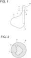
FIG. 1 is a schematic side view of a workpiece. -
FIG. 2 is a cross-sectional view taken along line A-A inFIG. 1 . -
FIG. 3 is a schematic side view of a cutting apparatus according to an embodiment. -
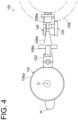
FIG. 4 is a top view seen from direction B inFIG. 3 . -
FIG. 5 is an enlarged view of the vicinity of a contact surface of a holding member. - Embodiments will now be described in detail with reference to the accompanying drawings. It is intended, however, that unless particularly identified, dimensions, materials, shapes, relative positions, and the like of components described in the embodiments shall be interpreted as illustrative only and not intended to limit the scope of the present invention.
- First, a workpiece W to be cut by a
cutting apparatus 100 will be described with reference toFIGs. 1 and 2. FIG. 1 is a schematic side view of the workpiece W.FIG. 2 is a cross-sectional view taken along line A-A inFIG. 1 . - The workpiece W is so-called bone-in meat with a
meat portion 2 around abone portion 1. In this embodiment, the bone-in meat, specifically a leg of turkey, is treated as the workpiece W, but there are no restrictions on the type or part of the meat, such as beef, pork, chicken, etc. As shown inFIG. 1 , the workpiece W has abody part 4 with a large amount of themeat portion 2 relative to thebone portion 1, and anankle part 6 that is relatively smaller in thickness and haslittle meat portion 2 than thebody part 4. Further, as shown inFIG. 2 , thebone portion 1 has a non-perfect circular cross-section, and atendon 5 is on a portion of the outer surface of thebone portion 1. Thetendon 5 is a tissue that extends along the outer surface of thebone portion 1 and is harder than themeat portion 2. - Next, a
cutting apparatus 100 for cutting the workpiece W having the above configuration will be described.FIG. 3 is a schematic side view of thecutting apparatus 100 according to an embodiment.FIG. 4 is a top view seen from direction B inFIG. 3 . - The
cutting apparatus 100 is an apparatus for performing the so-called ankle cutting process, in which a cut is made in theankle part 6 along the circumference of thebone portion 1 as pre-processing for separating themeat portion 2 from thebone portion 1 in the workpiece W. In the ankle cutting process, a cut is made in theankle part 6 along the circumferential direction, which serves as the starting point for the subsequent separation of themeat portion 2 from thebone portion 1. In this process, thecutting apparatus 100 must properly cut themeat portion 2 around thebone portion 1 and thetendon 5, a relatively hard portion which hinders the separation. Further, in the slitting process using thecutting apparatus 100, if thebone portion 1 is also cut, themeat portion 2 may not be properly separated from thebone portion 1 in the subsequent process for separation of themeat portion 2, or a part of thebone portion 1 may be separated together with themeat portion 2 and thus may be mixed in as a foreign substance with the processed meat after processing. Therefore, thecutting apparatus 100 is required to properly cut themeat portion 2 and thetendon 5 in theankle part 6, while avoiding cutting to thebone portion 1. - The
cutting apparatus 100 is equipped with aclamper 102 for rotatably supporting the workpiece W. Theclamper 102 is configured to grip one end of the workpiece W close to theankle part 6. Although the detailed structure of theclamper 102 will not be described, in this embodiment, theclamper 102 supports the workpiece W so that theankle part 6, which is the portion to be cut by thecutting apparatus 100, is exposed below while one end of the workpiece W is inserted in theclamper 102. - Further, the
cutting apparatus 100 is incorporated as part of each step in a series of meat processing process to separate themeat portion 2 from thebone portion 1. Theclamper 102 can move along a rail (not shown) to sequentially convey the workpiece W to each step. Specifically, theclamper 102 can move along the rail (not shown) to carry in the workpiece W before cutting to thecutting apparatus 100 and carry out the workpiece W cut by thecutting apparatus 100 to the next step. - The
cutting apparatus 100 is equipped with acutter 104 for cutting theankle part 6 of the workpiece W. Thecutter 104 is a disk-shaped cutter with an arc-shapedtooth surface 104a, supported around a central axis C along a substantially vertical direction (the central axis C is fixed to an unshown peripheral structure). Thecutter 104 is installed so that thetooth surface 104a is substantially horizontal with respect to the central axis C and facing one side of theankle part 6, which is the portion of the workpiece W gripped by theclamper 102 to be cut. - The
tooth surface 104a of thecutter 104 may be straight. - The
cutting apparatus 100 is equipped with a holdingmember 106 for restraining the workpiece W supported by theclamper 102 from the opposite side from thecutter 104. The holdingmember 106 is placed on the opposite side of the workpiece W from thecutter 104. Thus, the workpiece W is restrained by the holdingmember 106, and thecutter 104 is brought into contact with theankle part 6 from the opposite side from the holdingmember 106. When theclamper 102 is rotated in this state by driving force from an external source, the workpiece W supported by theclamper 102 rotates while being restrained by the holdingmember 106 between the holdingmember 106 and thecutter 104, so that theankle part 6 is cut along the circumferential direction. - It is preferable that the position where the
tooth surface 104a of thecutter 104 is in contact with the workpiece W and the position where the holdingmember 106 is in contact with the workpiece W are of substantially equal height, but as shown inFIG. 3 , there may be some difference in height between the two positions. - The holding
member 106 has anarm part 106a and acontact part 106b. Thearm part 106a has a shape that allows thecontact part 106b at its tip to be in contact with a predetermined portion of the workpiece W. As described above, thecontact part 106b is configured to come into contact with the workpiece W at a height approximately equal to the position where thetooth surface 104a of thecutter 104 is in contact with the workpiece W. In this embodiment, as described below, the holdingmember 106 is capable of switching between the first position P1 and the second position P2 (inFIG. 3 , the first position P1 is shown by the double-dotted dashed line and the second position P2 by the solid line). In the first position P1, the holdingmember 106 takes a posture in which thecontact part 106b is in contact with the workpiece W. In the second position P2, the holdingmember 106 takes a posture in which thecontact part 106b is retracted from the workpiece W. - The
contact part 106b is the portion in contact with the workpiece W when the holdingmember 106 is in the first position P1. In this embodiment, thecontact part 106b is formed to increase in width toward the side that contacts the workpiece W. As a result, even if the size of the workpiece W varies, the workpiece W can be caught by thecontact part 106b accurately, and thecontact part 106b can be securely brought into contact with the workpiece W. -
FIG. 5 is an enlarged view of the vicinity of thecontact surface 106c of the holdingmember 106. As shown inFIG. 5 , thecontact surface 106c of thecontact part 106b which contacts the workpiece W may have a recess 106d corresponding to the shape of the outer surface of the workpiece W. Thus, when thecontact part 106b comes into contact with the workpiece W, a part of the workpiece W engages the recess 106d, so that the workpiece W can be caught by thecontact part 106b more accurately. - The
contact part 106b may be detachable from thearm part 106a. In this case, by replacing thecontact part 106b, it can be used for a wider range of sizes and types of workpieces W. - The
cutting apparatus 100 is equipped with asupport part 108 for elastically supporting the holdingmember 106. Thesupport part 108 elastically supports the holdingmember 106 with respect to aperipheral structure 109 of thecutting apparatus 100. As a result, the holdingmember 106 supported by thesupport part 108 restrains the workpiece W with a predetermined elastic force. Thus, even if the size of the workpiece W varies, the holdingmember 106 can adjust the degree of contact of thecutter 104, which is located on the opposite side of the workpiece W, by rocking the holdingmember 106 according to the size of the workpiece W. For example, if the workpiece W is small, the depth of cut of thecutter 104 into the workpiece W is adjusted to the extent that there is no uncut portion of themeat portion 2 or thetendon 5 of the workpiece W. On the other hand, if the workpiece W is large, the depth of cut of thecutter 104 into the workpiece W is adjusted so that themeat portion 2 and thetendon 5 can be accurately cut without cutting thebone portion 1 in the workpiece W. Thus, by elastically supporting the holdingmember 106 with thesupport part 108, the degree of contact of thecutter 104 with the workpiece W restrained by the holdingmember 106 is adjusted according to the size of the workpiece W, and a required portion of the workpiece W can be cut properly. - The
support part 108 is capable of switching between the first position P1 where the holdingmember 106 is in contact with the workpiece W supported by theclamper 102 and the second position P2 where the holdingmember 106 is separated from the workpiece W supported by theclamper 102. In the case where the holdingmember 106 is switched to the first position P1, as described above, the workpiece W is elastically restrained by the holding member 106 (the holdingmember 106 is elastically pressed against the workpiece W), so that a required portion of the workpiece W can be cut properly. On the other hand, in the case where the holdingmember 106 is switched to the second position P2, for example, the holdingmember 106 can be retracted when the workpiece W supported by theclamper 102 is conveyed along a predetermined track to prevent interference between the conveyed workpiece W and the holdingmember 106. - The
support part 108 for elastically supporting the holdingmember 106 includes, for example, anair cylinder 110. In this case, by adjusting the air pressure of theair cylinder 110, the magnitude of elastic force of thesupport part 108 to support the holdingmember 106 can be easily changed. This allows adjustment of the magnitude of elastic force to restrain the workpiece W by the holding member 106 (in other words, elastic force with which the workpiece W is held by the holding member 106) when the holdingmember 106 is switched to the first position P1. For example, if the amount of cut into the workpiece W is small (e.g., if uncut portions are prone to remain in themeat portion 2 or the tendon 5), the air pressure of theair cylinder 110 may be adjusted so that the elastic force increases to appropriately improve the amount of cut into the workpiece W. On the other hand, if the amount of cut into the workpiece W is too much (e.g., if the cut extends to thebone portion 1 as well as themeat portion 2 and the tendon 5), the air pressure of theair cylinder 110 may be adjusted so that the elastic force decreases to reduce the amount of cutting with thecutter 104 into the workpiece W and appropriately improve the amount of cut into the workpiece W. For example, the user may change the setting of theair cylinder 110 for such adjustment of elastic force to suitably control the cutting quality of the workpiece W. - As another aspect of the
support part 108, for example, a member capable of providing the elastic force, such as a spring member, may be used. - In the above-described embodiment, the case in which the
cutter 104 is fixed to the peripheral structure (not shown) is illustrated, but thecutter 104 may also be elastically supported by the peripheral structure. In this case, the workpiece W gripped by theclamper 102 is rotated while being elastically restrained from both sides by thecutter 104 and the holdingmember 106, which allows finer adjustment of the cutting quality along the circumference of theankle part 6. - As described above, according to the above-described embodiment, the holding
member 106 for restraining the workpiece W is elastically supported by thesupport part 108 when the workpiece W is rotated and cut with thecutter 104. Thus, even if the size of the workpiece W varies, the holdingmember 106 can be rocked by the elastic force received according to the size of the workpiece W. Therefore, the degree of contact of thecutter 104 with the workpiece W restrained by the holdingmember 106 is adjusted according to the size of the workpiece W, and a required portion of the workpiece W can be cut properly. Thus, it is possible to provide thecutting apparatus 100 capable of cutting a required portion properly regardless of the size of bone-in meat. -
- 1
- Bone portion
- 2
- Meat portion
- 4
- Body part
- 5
- Tendon
- 6
- Ankle part
- 100
- Cutting apparatus
- 102
- Clamper
- 104
- Cutter
- 104a
- Tooth surface
- 106
- Holding member
- 106a
- Arm part
- 106b
- Contact part
- 106c
- Contact surface
- 106d
- Recess
- 108
- Support part
- 109
- Peripheral structure
- 110
- Air cylinder
- C
- Central axis
- P1
- First position
- P2
- Second position
- W
- Workpiece
Claims (7)
- A cutting apparatus, comprising:a clamper for rotatably supporting a workpiece which is a bone-in meat;a cutter for cutting a string in the workpiece by bringing the cutter into contact with the workpiece while rotating the workpiece supported by the clamper;a holding member for restraining the workpiece supported by the clamper from an opposite side from the cutter; anda support part elastically supporting the holding member.
- The cutting apparatus according to claim 1,
wherein the support part is capable of switching between a first position where the holding member is in contact with the workpiece supported by the clamper and a second position where the holding member is separated from the workpiece supported by the clamper. - The cutting apparatus according to claim 1 or 2,
wherein magnitude of elastic force of the support part to support the holding member is variable. - The cutting apparatus according to claim 1 or 2,
wherein the support part includes an air cylinder for providing elastic force to support the holding member. - The cutting apparatus according to claim 1 or 2,wherein the holding member has a contact surface capable of contacting the workpiece, andwherein the contact surface has a recess corresponding to a surface shape of the workpiece.
- The cutting apparatus according to claim 1 or 2,
wherein the cutter is elastically supported. - The cutting apparatus according to claim 1 or 2,
wherein the workpiece has a non-perfect circular cross-section at a position where the workpiece is cut by the cutter.
Applications Claiming Priority (2)
| Application Number | Priority Date | Filing Date | Title |
|---|---|---|---|
| JP2022126570A JP2024023033A (en) | 2022-08-08 | 2022-08-08 | cutting device |
| PCT/JP2023/021551 WO2024034249A1 (en) | 2022-08-08 | 2023-06-09 | Cutting device |
Publications (3)
| Publication Number | Publication Date |
|---|---|
| EP4374702A1 true EP4374702A1 (en) | 2024-05-29 |
| EP4374702A4 EP4374702A4 (en) | 2025-01-08 |
| EP4374702B1 EP4374702B1 (en) | 2026-05-20 |
Family
ID=89851294
Family Applications (1)
| Application Number | Title | Priority Date | Filing Date |
|---|---|---|---|
| EP23852233.8A Active EP4374702B1 (en) | 2022-08-08 | 2023-06-09 | CUTTING DEVICE |
Country Status (4)
| Country | Link |
|---|---|
| US (1) | US12279624B2 (en) |
| EP (1) | EP4374702B1 (en) |
| JP (1) | JP2024023033A (en) |
| WO (1) | WO2024034249A1 (en) |
Family Cites Families (13)
| Publication number | Priority date | Publication date | Assignee | Title |
|---|---|---|---|---|
| US3766604A (en) * | 1972-12-26 | 1973-10-23 | Hormel & Co Geo A | Hinged suspension device |
| US4843682A (en) * | 1986-12-05 | 1989-07-04 | Bowen David G | Poultry deboner |
| NL1006286C2 (en) * | 1997-06-11 | 1998-12-14 | Tieleman Food Equipment B V | Suspended transport system for slaughtered chickens or other poultry. |
| NL1012703C2 (en) * | 1999-04-06 | 2000-10-09 | Stork Pmt | Method and device for processing a poultry leg. |
| ES2432181T3 (en) * | 2008-05-12 | 2013-12-02 | Mayekawa Mfg. Co., Ltd. | Boning procedure and boning device for front or rear leg |
| US8882571B2 (en) * | 2011-01-26 | 2014-11-11 | Foodmate Bv | Method of deboning animal thighs for separating and collecting meat therefrom and apparatus for performing the method |
| NL2011361C2 (en) * | 2013-08-30 | 2014-11-03 | Marel Stork Poultry Proc Bv | METHOD FOR CUTTING AN ANIMAL SUSPENDED WITH THE LEGS ON A CARRIER OF A TRANSPORTER |
| AU2015251705B2 (en) | 2014-04-23 | 2018-01-04 | Mayekawa Mfg. Co., Ltd. | Device and method for deboning meat with bone |
| CN205794678U (en) * | 2016-06-17 | 2016-12-14 | 赣县田村镇富强农业专业合作社 | A kind of efficient slaughter device of pressed salted duck |
| KR101915019B1 (en) * | 2016-10-06 | 2018-11-06 | 주식회사 태진 | Boning Apparatus for Thigh of Chicken |
| WO2019131357A1 (en) * | 2017-12-25 | 2019-07-04 | 株式会社前川製作所 | Device for measuring entire length of bone-in meat and method for measuring entire length of bone-in meat |
| DK3603404T3 (en) * | 2017-12-25 | 2022-04-04 | Maekawa Seisakusho Kk | NON-BONE MEAT PROCESSING SYSTEM AND SEPARATED MEAT MANUFACTURING METHOD |
| AU2022418710B2 (en) * | 2021-12-20 | 2025-01-02 | Mayekawa Mfg. Co., Ltd. | Poultry leg meat deboning device and poultry leg meat deboning method |
-
2022
- 2022-08-08 JP JP2022126570A patent/JP2024023033A/en active Pending
-
2023
- 2023-06-09 US US18/575,902 patent/US12279624B2/en active Active
- 2023-06-09 WO PCT/JP2023/021551 patent/WO2024034249A1/en not_active Ceased
- 2023-06-09 EP EP23852233.8A patent/EP4374702B1/en active Active
Also Published As
| Publication number | Publication date |
|---|---|
| US12279624B2 (en) | 2025-04-22 |
| US20250000105A1 (en) | 2025-01-02 |
| JP2024023033A (en) | 2024-02-21 |
| EP4374702B1 (en) | 2026-05-20 |
| EP4374702A4 (en) | 2025-01-08 |
| WO2024034249A1 (en) | 2024-02-15 |
Similar Documents
| Publication | Publication Date | Title |
|---|---|---|
| US8801508B2 (en) | Apparatus and method for separating the wishbone from eviscerated poultry carcasses | |
| EP3603405B1 (en) | Bone-meat separation apparatus for bone-including limb meat and bone-meat separation method for bone-including limb meat | |
| EP0159077B1 (en) | Method and device for severing a body part of slaughtered poultry | |
| CN105120673B (en) | Device and method for mechanical processing of headless and at least eviscerated fish conveyed with the tail facing forward in the conveying direction T of the conveying path | |
| EP2356908A3 (en) | Method and device for processing a carcass part of slaughtered poultry | |
| JP2001149001A (en) | Method of automatically making cut for removing bone from chicken dark meat and unit for making the same | |
| US12279624B2 (en) | Cutting apparatus | |
| US20190291188A1 (en) | Vibration cutting insert | |
| JP2002010732A (en) | Method for separating thigh and device therefor | |
| CA2263288A1 (en) | Apparatus, tool and method for mechanical removal of a spinal column part from a part carcass | |
| WO2019131362A1 (en) | Device for forming slit in bone-in meat and method for forming slit in bone-in meat | |
| EP3099179B1 (en) | Method and apparatus for measuring meat products moving sequentially along a meat processing line | |
| CN111432642B (en) | Carrier for holding poultry carcasses | |
| CN117177671B (en) | Poultry leg meat cutting device and poultry leg meat automatic cutting method | |
| JP7125536B2 (en) | Cross-cut device and method for stabilizing squeeze cut edges | |
| JP7619932B2 (en) | Meat separator and device for removing meat from bones | |
| AU2023268862B2 (en) | Slicing device, and method for slicing workpiece | |
| EP3515194B1 (en) | A fish decapitating apparatus and a method for decapitating fish | |
| AU2023268138B2 (en) | Round blade for slicing, slicing device, and slicing method for workpiece | |
| EP4277469B1 (en) | A fish filleting machine with a pelvic fin splitter and a method of filleting fish with two pelvic fins | |
| US11717002B2 (en) | Device and method for separating at least one tendon that connects a breast fillet of a gutted poultry body, or a part thereof, to a carcass of the poultry body, or a part thereof, and a tool unit therefor | |
| US20240389608A1 (en) | Poultry processing apparatus | |
| US12382968B2 (en) | Poultry processing apparatus | |
| JP2024092453A (en) | Meat Processing Equipment | |
| JPH0573370B2 (en) |
Legal Events
| Date | Code | Title | Description |
|---|---|---|---|
| STAA | Information on the status of an ep patent application or granted ep patent |
Free format text: STATUS: THE INTERNATIONAL PUBLICATION HAS BEEN MADE |
|
| PUAI | Public reference made under article 153(3) epc to a published international application that has entered the european phase |
Free format text: ORIGINAL CODE: 0009012 |
|
| STAA | Information on the status of an ep patent application or granted ep patent |
Free format text: STATUS: REQUEST FOR EXAMINATION WAS MADE |
|
| 17P | Request for examination filed |
Effective date: 20240223 |
|
| AK | Designated contracting states |
Kind code of ref document: A1 Designated state(s): AL AT BE BG CH CY CZ DE DK EE ES FI FR GB GR HR HU IE IS IT LI LT LU LV MC ME MK MT NL NO PL PT RO RS SE SI SK SM TR |
|
| A4 | Supplementary search report drawn up and despatched |
Effective date: 20241210 |
|
| RIC1 | Information provided on ipc code assigned before grant |
Ipc: A22C 17/02 20060101ALI20241204BHEP Ipc: A22C 17/00 20060101ALI20241204BHEP Ipc: A22C 21/00 20060101AFI20241204BHEP |
|
| STAA | Information on the status of an ep patent application or granted ep patent |
Free format text: STATUS: EXAMINATION IS IN PROGRESS |
|
| 17Q | First examination report despatched |
Effective date: 20250807 |
|
| DAV | Request for validation of the european patent (deleted) | ||
| DAX | Request for extension of the european patent (deleted) | ||
| GRAP | Despatch of communication of intention to grant a patent |
Free format text: ORIGINAL CODE: EPIDOSNIGR1 |
|
| STAA | Information on the status of an ep patent application or granted ep patent |
Free format text: STATUS: GRANT OF PATENT IS INTENDED |
|
| INTG | Intention to grant announced |
Effective date: 20260219 |
|
| GRAS | Grant fee paid |
Free format text: ORIGINAL CODE: EPIDOSNIGR3 |
|
| GRAA | (expected) grant |
Free format text: ORIGINAL CODE: 0009210 |
|
| STAA | Information on the status of an ep patent application or granted ep patent |
Free format text: STATUS: THE PATENT HAS BEEN GRANTED |