EP4374200B1 - Illumination optical device comprising a collimator having low intrinsic noise - Google Patents
Illumination optical device comprising a collimator having low intrinsic noise Download PDFInfo
- Publication number
- EP4374200B1 EP4374200B1 EP22768937.9A EP22768937A EP4374200B1 EP 4374200 B1 EP4374200 B1 EP 4374200B1 EP 22768937 A EP22768937 A EP 22768937A EP 4374200 B1 EP4374200 B1 EP 4374200B1
- Authority
- EP
- European Patent Office
- Prior art keywords
- mirror
- collimator
- quaternary
- light beam
- tertiary
- Prior art date
- Legal status (The legal status is an assumption and is not a legal conclusion. Google has not performed a legal analysis and makes no representation as to the accuracy of the status listed.)
- Active
Links
Images



Classifications
-
- G—PHYSICS
- G02—OPTICS
- G02B—OPTICAL ELEMENTS, SYSTEMS OR APPARATUS
- G02B17/00—Systems with reflecting surfaces, with or without refracting elements
- G02B17/02—Catoptric systems, e.g. image erecting and reversing system
- G02B17/06—Catoptric systems, e.g. image erecting and reversing system using mirrors only, i.e. having only one curved mirror
- G02B17/0647—Catoptric systems, e.g. image erecting and reversing system using mirrors only, i.e. having only one curved mirror using more than three curved mirrors
- G02B17/0663—Catoptric systems, e.g. image erecting and reversing system using mirrors only, i.e. having only one curved mirror using more than three curved mirrors off-axis or unobscured systems in which not all of the mirrors share a common axis of rotational symmetry, e.g. at least one of the mirrors is warped, tilted or decentered with respect to the other elements
-
- G—PHYSICS
- G02—OPTICS
- G02B—OPTICAL ELEMENTS, SYSTEMS OR APPARATUS
- G02B19/00—Condensers, e.g. light collectors or similar non-imaging optics
- G02B19/0004—Condensers, e.g. light collectors or similar non-imaging optics characterised by the optical means employed
- G02B19/0019—Condensers, e.g. light collectors or similar non-imaging optics characterised by the optical means employed having reflective surfaces only (e.g. louvre systems, systems with multiple planar reflectors)
-
- G—PHYSICS
- G02—OPTICS
- G02B—OPTICAL ELEMENTS, SYSTEMS OR APPARATUS
- G02B19/00—Condensers, e.g. light collectors or similar non-imaging optics
- G02B19/0033—Condensers, e.g. light collectors or similar non-imaging optics characterised by the use
- G02B19/0047—Condensers, e.g. light collectors or similar non-imaging optics characterised by the use for use with a light source
-
- G—PHYSICS
- G02—OPTICS
- G02B—OPTICAL ELEMENTS, SYSTEMS OR APPARATUS
- G02B27/00—Optical systems or apparatus not provided for by any of the groups G02B1/00 - G02B26/00, G02B30/00
- G02B27/0018—Optical systems or apparatus not provided for by any of the groups G02B1/00 - G02B26/00, G02B30/00 with means for preventing ghost images
-
- G—PHYSICS
- G02—OPTICS
- G02B—OPTICAL ELEMENTS, SYSTEMS OR APPARATUS
- G02B5/00—Optical elements other than lenses
- G02B5/003—Light absorbing elements
Definitions
- the present invention relates to an illumination optical device comprising a collimator.
- the invention refers to an illumination device or projector that can be used to obtain an Optical Ground Support Equipment (OGSE) capable of testing, calibrating and/or verifying the optical characteristics of an electro-optical device.
- OGSE Optical Ground Support Equipment
- the present invention finds advantageous but not exclusive application in the aerospace field.
- an electro-optical device may be subjected to one or more test and verification steps before the actual use on field of the electro-optical device itself, especially in applications where high reliability of the electro-optical device is required.
- Optical Ground Support Equipment is known to be used to verify the optical performance of various electro-optical devices during specific Assembly Integration and Test (AIT) or Assembly and Integration Test (AIT) activities.
- the stray light is generally defined as a light noise component that is generated by an optical device, e.g. formed by light that is propagated following an optical path different from a desired optical path.
- Analysing the stray light generated by a unit under test thus allows to verify the optical performance of the unit under test.
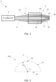
- Figure 1 shows a system 1 comprising a known illumination device or illuminator 3 and a unit under test 5 having an optical architecture 5A and an optical detector 5B.
- the illuminator 3 comprises one or more light sources and a collimator (not shown here) and is configured to generate a light beam 7 that propagates towards the unit under test 5.
- the light beam 7 comprises a collimated portion 9, which constitutes a desired collimated optical stimulus for the unit under test 5, and a stray portion 10, which constitutes a non-collimated noise light radiation.
- the stray portion 10 constitutes a signature of the illuminator 3 and is generated by imperfections inside the illuminator 3 itself, in particular of the respective collimator.
- the optical architecture 5A receives the optical beam 7 and generates a device light beam 13, focused on the detector 5B.
- the optical architecture 5A receives and propagates both the collimated component 9 and the stray component 10 of the optical beam 7.
- the device light beam 13 comprises both a primary portion 14 and an illuminator stray portion 15.
- the primary portion 14 forms the desired optical signal output by the optical architecture 5A, i.e. the optical signal generated starting from the collimated portion 10 of the optical beam 7.
- the illuminator stray portion 15 forms a noise signal generated starting from the stray portion 10 of the optical beam 7, and thus dependent on the optical properties of the illuminator 3.
- the optical architecture 5A may generate a device stray light component 16, starting from the collimated portion 9 of the optical beam 7, due to imperfections of the optical elements, e.g. mirrors, lenses, etc. that form the optical architecture 5A. Consequently, the device optical beam 13 also comprises a device stray portion 17, generated starting from the device stray light component 16.
- the optical detector 5B receives the device optical beam 13, it detects the primary portion 14 thereof, the illuminator stray portion 15 and the device stray portion 17.
- the presence of the illuminator stray portion 15 in the device optical beam 13 makes it difficult, if not impossible, to isolate the device stray portion 17, or to isolate the noise contribution introduced by the unit under test 5.
- the fact that the illuminator 3 generates a stray portion of light does not allow to isolate the noise contribution introduced by the unit under test 5, i.e. it does not allow to reliably verify the performance of the optical unit under test 5, during the testing steps.
- Relevant prior art can be found in ROLT, STEPHEN ET AL: "A four mirror anastigmat collimator design for optical payload calibration",PROCEEDINGS OF SPIE; [PROCEEDINGS OF SPIE ISSN 0277-786X VOLUME 10524], SPIE, US, vol.
- Aim of the present invention is to overcome the disadvantages of the prior art.
- an illumination optical device comprising a collimator, as defined in the appended claims.
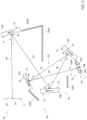
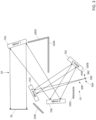
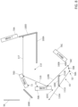
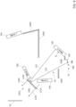
- FIGS 2-4 show an illumination device, hereinafter referred to as an illuminator 50, comprising an extended light source 52, a collimator 54 having an input focal plane F 1 and an output focal plane F 2 and defining a collimator optical path 80, and an aperture or pupil 56, mutually optically coupled.
- an illumination device hereinafter referred to as an illuminator 50
- an extended light source 52 comprising an extended light source 52, a collimator 54 having an input focal plane F 1 and an output focal plane F 2 and defining a collimator optical path 80, and an aperture or pupil 56, mutually optically coupled.
- the extended light source 52 is of a known type, e.g. an LED source or any other type of known source, of monochromatic or polychromatic type, configured to generate a light radiation 60, schematically represented by arrows in Figure 2 , propagating from the extended light source 52.
- the light radiation 60 comprises electromagnetic radiation in the frequency range between infrared and ultraviolet.
- the light radiation 60 is formed by a primary light beam 63 ( Figure 4 ), propagating along directions intercepting the quaternary mirror 70D so as to follow the collimator optical path 80, and a secondary light beam 65 ( Figures 6-9 ), propagating along directions not intercepting the quaternary mirror 70D.
- the extended light source 52 is arranged in the input focal plane F 1 of the collimator 54 and the aperture 56 is arranged in the output focal plane F 2 , so that the primary light beam 63 is collimated, by the collimator 54, in an output beam 64 having a flat wavefront on the aperture 56, as schematically shown in Figure 4 .
- the extended light source 52 is represented in Figures 2-4 by three mutually distinct point sources and hereinafter referred to as first point source 58A, second point source 58B and third point source 58C.
- the point sources 58A-58C each emit a respective optical beam 66A-66C having a spherical wavefront, the propagation of which along the collimator optical path 80 is schematically shown in Figure 4 .
- Figure 3 shows in detail the propagation of the optical beam 66B of the second point source 58B along the collimator optical path 80.
- the three point sources 58A-58C may be sources equal to or different from one another, for example each having a respective frequency or they may each represent a respective pixel of the extended light source 52.
- first and third point source 58A, 58C are arranged at two end points of the extended light source 52.
- the second point source 58B is arranged at a midpoint of the extended light source 52.
- the collimator 54 is a collimator of the Schiefspiegler type, i.e. comprising a plurality of mirrors 70 arranged off-axis and mutually tilted so as to form an unobstructed optical path.
- the collimator 54 comprises four mirrors: a primary mirror 70A, a secondary mirror 70B, a tertiary mirror 70C, and a quaternary mirror 70D, each having a respective reflective surface 72 and a respective support surface 74.
- the mirrors 70A-70D are preferably spherical mirrors, each concave or convex.
- the mirrors 70A-70D each have a respective focal ratio, which may be chosen depending on the specific design of the collimator 54.
- Figure 5 shows by way of example a cross-section of the primary mirror 70A, here of concave type, whose reflective surface 72 has a radius of curvature R 1 with respect to a centre O defined on the support surface 74.
- the primary mirror 70A has a vertex 76, on the reflective surface 72, formed by the intersection between the reflective surface 72 and a mirror axis S passing through the centre O and perpendicular to the support surface 74.
- the secondary mirror 70B, the tertiary mirror 70C and the quaternary mirror 70D also have a respective radius of curvature R 2 , R 3 , R 4 and a respective vertex 76 defined by a respective mirror axis S.
- the collimator optical path 80 of the collimator 54 comprises, in succession, the extended light source 52 (here arranged in the input focal plane F 1 ), the quaternary mirror 70D, the tertiary mirror 70C, the secondary mirror 70B, the primary mirror 70A and the aperture 56 (here arranged in the output focal plane F 2 ).
- the collimator optical path 80 has a collimator optical axis 82, indicated by a succession of arrows in Figure 2 , comprising a first stretch 84, a second stretch 85, a third stretch 86, a fourth stretch 87 and a fifth stretch 88.
- the first stretch 84 of the collimator optical axis 82 extends between the second point source 58B and the vertex 76 of the quaternary mirror 70D.
- the second stretch 85 of the collimator optical axis 82 extends between the vertex 76 of the quaternary mirror 70D and the vertex 76 of the tertiary mirror 70C.
- the third stretch 86 of the collimator optical axis 82 extends between the vertex 76 of the tertiary mirror 70C and the vertex 76 of the secondary mirror 70B.
- the fourth stretch 87 of the collimator optical axis 82 extends between the vertex 76 of the secondary mirror 70B and the vertex 76 of the primary mirror 70A.
- the fifth stretch 88 of the collimator optical axis 82 extends between the vertex 76 of the primary mirror 70A and a point of the aperture 56, in particular a midpoint M of the aperture 56.
- the first stretch 84 defines a distance e 4 between the extended light source 52 and the quaternary mirror 70D
- the second stretch 85 defines a distance e 3 between the quaternary mirror 70D and the tertiary mirror 70C
- the third stretch 86 defines a distance e 2 between the tertiary mirror 70C and the secondary mirror 70B
- the fourth stretch 87 defines a distance e 1 between the secondary mirror 70B and the primary mirror 70A.
- the mirror axis S of the primary mirror 70A forms a tilt angle ⁇ 1 with respect to the fifth stretch 88 of the collimator optical axis 82.
- the mirror axis S of the secondary mirror 70B forms a tilt angle ⁇ 2 with respect to the fourth stretch 87 of the collimator optical axis 82.
- the mirror axis S of the tertiary mirror 70C forms a tilt angle ⁇ 3 with respect to the third stretch 86 of the collimator optical axis 82.
- the mirror axis S of the quaternary mirror 70D forms a tilt angle ⁇ 4 with respect to the second stretch 85 of the collimator optical axis 82.
- the mirror axis S of the quaternary mirror 70D and the mirror axis S of the primary mirror 70A form between them an angle comprised between 89° and 91°, in particular approximately of 90°. In this way, in use, it is possible to avoid that the main light beam 63, after impinging on the quaternary mirror 70D, is reflected towards the primary mirror 70A.
- first stretch 84 of the collimator optical axis 82 forms a tilt angle ⁇ S with a source axis Ss perpendicular to the focal plane F of the collimator 54 and passing through the second point source 58B.
- the distance between the mirrors 70A-70D, the tilt angle and the radius of curvature of the mirrors 70A-70D may be determined, at the design stage, as a function of a desired effective focal length of the collimator 54 and/or of a frequency range of the light radiation 60 generated by the extended light source 52.
- the distance between the mirrors 70A-70D, the tilt angle and the radius of curvature of the mirrors 70A-70D may be chosen, at the design stage, so as to eliminate, in the first approximation, the aberrations of the collimator 54.
- the mirrors 70A-70D may be designed to reduce the aberrations of coma C and astigmatism A, as described in Patent Application US 5142417 A .
- the tilt angle ⁇ 3 of the tertiary mirror 70C is lower than 25°.
- the distance e 1 between the primary mirror 70A and the secondary mirror 70B is comprised between a factor 0.4 and 0.6 of the focal length of the primary mirror 70A.
- the primary mirror 70A may be a concave spherical mirror and the secondary mirror 70B a convex spherical mirror.
- the quaternary mirror 70D may be a flat mirror, i.e. mathematically representable as a spherical mirror having infinite radius of curvature R 4 .
- the specific three-dimensional arrangement of the mirrors 70A-70D may be chosen at the design stage depending on the specific application of the collimator 54.
- the mirrors 70A-70D may be mounted on a single optical working plane, so that the collimator optical axis 82 lies on a single plane.
- the mirrors 70A-70D may have a different three-dimensional arrangement.
- the collimator 54 further comprises a plurality of baffles 100A-100E, hereinafter individually referred to as first baffle 100A, second baffle 100B, third baffle 100C, fourth baffle 100D, and fifth baffle 100E, each configured to prevent a reflection of an incident light beam.
- baffles 100A-100E hereinafter individually referred to as first baffle 100A, second baffle 100B, third baffle 100C, fourth baffle 100D, and fifth baffle 100E, each configured to prevent a reflection of an incident light beam.
- the baffles 100A-100E may each be of an opaque material, e.g., a thin metal plate, configured to absorb an incident light radiation.
- first and the fourth baffle 100A, 100D are formed as one piece; the second, the third, and the fifth baffle 100B, 100C, 100E are distinct from each other.
- the baffles 100A-100E may form portions of a single absorbent body, as shown for example in Figure 12 .
- the first baffle 100A has a first end 103A and a second end 103B and is arranged between the extended light source 52 and the primary mirror 70A, so as to form a first shadow region 105A of the secondary light beam 65 of the extended light source 52.
- the first shadow region 105A is delimited by a first boundary ray 106A and a second boundary ray 106B, and is an umbra region of the extended light source 52.
- the first boundary ray 106A belongs to the secondary light beam 65 and is a ray generated by the first point source 58A and passing contiguous to the first end 103A of the first baffle 100A.
- the second boundary ray 106B belongs to the secondary light beam 65 and is a ray generated by the third point source 58C and passing contiguous to the second end 103B of the first baffle 100A.
- the primary mirror 70A in particular the respective reflective surface 72, is arranged in the first shadow region 105A.
- the first baffle 100A ensures that no portion of the secondary light beam 65 of the extended light source 52 directly impinges on the reflective surface 72 of the primary mirror 70A.
- the second baffle 100B extends between a first end 107A and a second end 107B and is arranged between the extended light source 52 and the tertiary mirror 70C, so as to form a second shadow region 105B of the secondary light beam 65 of the extended light source 52.
- the second shadow region 105B is delimited by a first boundary ray 108A and a second boundary ray 108B, and is an umbra region of the extended light source 52.
- the first boundary ray 108A belongs to the secondary light beam 65 and is a ray generated by the first point source 58A and passing contiguous to the first end 107A of the second baffle 100B.
- the second boundary ray 108B belongs to the secondary light beam 65 and is a ray generated by the third point source 58C and passing contiguous to the second end 107B of the second baffle 100B.
- the tertiary mirror 70C in particular the respective reflective surface 72, is arranged in the second shadow region 105B.
- the second baffle 100B ensures that no portion of the secondary light beam 65 directly impinges on the reflective surface 72 of the tertiary mirror 70C.
- the third baffle 100C extends between a first end 111A and a second end 111B and is arranged between the extended light source 52 and the secondary mirror 70B, so as to form a third shadow region 105C of the secondary light beam 65 of the extended light source 52.
- the third shadow region 105C is delimited by a first boundary ray 110A and a second boundary ray 110B, and is an umbra region of the extended light source 52.
- the first boundary ray 110A belongs to the secondary light beam 65 and is a ray generated by the first point source 58A and passing contiguous to the first end 111A of the third baffle 100C.
- the second boundary ray 110B belongs to the secondary light beam 65 and is a ray generated by the third point source 58C and passing contiguous to the second end 111B of the third baffle 100C.
- each ray of the secondary light beam 65 propagating between the first and the second boundary ray 110A, 110B impinges on the third baffle 100C and is absorbed by it.
- the secondary mirror 70B in particular the respective reflective surface 72, is partially arranged in the third shadow region 105C.
- the second boundary ray 110B of the third shadow region 105C impinges, in use, on the reflective surface 72 of the secondary mirror 70B.
- the secondary mirror 70B and the quaternary mirror 70D are mutually tilted of an angle comprised between 89° and 91°, in particular approximately of 90°.
- the secondary mirror 72, the quaternary mirror 70D, and the fourth baffle 100D form a trap optical path 115.
- the secondary mirror 70B reflects the second boundary ray 110B and forms a first reflected ray 116 incident on the reflective surface 72 of the quaternary mirror 70D.
- the quaternary mirror 70D reflects the first reflected ray 116 and forms a second reflected ray 117 incident on the fourth baffle 100D.
- the secondary mirror 70B is partially shaded with respect to the extended light source 52, so that part of the secondary light beam 65 incident directly on the reflective surface 72 of the secondary mirror 70B follows the trap optical path 115 and is then absorbed by the fourth baffle 100D.
- the fifth baffle 100E extends between a first end 121A and a second end 121B and is arranged between the secondary mirror 70B and the quaternary mirror 70D.
- the fifth baffle 100E forms a fourth shadow region 105D both with respect to the extended light source 52 and with respect to rays reflected by the tertiary mirror 70C that are external to the collimator optical path 80, i.e. with respect to rays reflected by the tertiary mirror 70C that are not directed towards the secondary mirror 70B.
- the fourth shadow region 105D is delimited by a first boundary ray 120A passing contiguous to the first end 121A of the fifth baffle 100E and by a second boundary ray 120B passing contiguous to the second end 121B of the fifth baffle 100E, and is an umbra region of the extended light source 52 and of the tertiary mirror 70C.
- the aperture 56 is arranged in the fourth shadow region 105D.
- each light ray, identified by way of example by an arrow 125 in Figure 9 which is reflected by the tertiary mirror 70C, passes between the quaternary mirror 70D and the secondary mirror 70B, and is directed toward the aperture 56 impinges on the fifth baffle 100E.
- the baffles 100A-100E and the mutual arrangement of the quaternary mirror 70D and of the primary mirror 70A ensure that only the light rays generated by the extended light source 52 and following the collimator optical path 80 (i.e., the primary light beam 63 of the light radiation 60 of Figure 4 ) reach the aperture 56.
- the collimator 80 has low intrinsic noise.
- the stray light that is, the light rays that do not follow the collimator optical path 80, generated inside the illuminator 50, does not reach the aperture 56.
- the illuminator 50 outputs, through the pupil 56, only the collimated output beam 64, which followed the collimator optical path 80.
- the illuminator 50 therefore has a low signature. In other words, the illuminator 50 has a low intrinsic noise.
- Figure 10 shows a different embodiment of the present illuminator, here indicated by 150.
- the illuminator 150 has a same structure as the one of the illuminator 50 of Figures 2-9 , except for the differences discussed below. Thus, common elements are indicated by the same reference numerals and the illuminator 150 will be described only with reference to the differences compared to the illuminator 50.
- the illuminator 150 comprises the extended light source 52, the aperture 56 and a collimator, here denoted by 154.
- the collimator 154 comprises, also in this embodiment, the mirrors 70A-70D, the first baffle 100A, the second baffle 100B, the third baffle 100C, the fourth baffle 100D, and an absorbent structure 200F including the fifth baffle 100E.
- the absorbent structure 200F further comprises two encapsulation portions 201A, 201B.
- the encapsulation portion 201A forms a single piece with the fifth baffle 100E.
- the encapsulation portions 201A, 201B laterally delimit the aperture 56 and the final stretch of the collimator optical path 80, i.e. the fifth stretch 88 of the collimator optical axis 82.
- the encapsulation portions 201A, 201B form further portions for absorbing the stray light of the illuminator 154; they thus contribute to further decreasing the signature of the collimator 154.
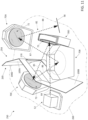
- Figure 11 shows a perspective view of a further embodiment of the present illuminator, here indicated by 250.
- the illuminator 250 has a same structure as the one of the illuminator 50 of Figures 2-9 , except for the differences discussed below. Thus, common elements are indicated by the same reference numerals and the illuminator 250 will be described only with reference to the differences compared to the illuminator 50.
- the illuminator 250 is formed by the extended light source 52, the aperture 56 (shown only schematically in Figure 12 ) and by a collimator, here indicated by 254 and comprising the mirrors 70A-70D.
- the mirrors 70A-70D and the extended light source 52 are mounted on a working optical plane 260 such that the collimator optical axis 82 lies in a single plane parallel to the working optical plane 260.
- the collimator 254 also comprises here the first baffle 100A, the second baffle 100B, and the fourth baffle 100D.
- the third baffle and the fifth baffle are shown in transparency in Figure 11 , for clarity's sake.
- first baffle 100A, the second baffle 100B and the fourth baffle 100D are mutually contiguous to portions forming a single absorbent body 265 having a through cavity 270.
- the first, the second, and the third stretch 84, 85, and 86 of the collimator optical axis 82 pass through the through cavity 270.
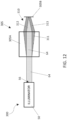
- the illuminators 50, 150, 250 may be used to obtain a system 300 for testing the stray light of a unit under test 305, as shown in Figure 12 .
- the illuminator 50 may be used to obtain an Optical Ground Support Equipment (OGSE) capable of testing, calibrating, and/or verifying the optical characteristics, in particular the optical characteristics of stray light, of the unit under test 305, during specific Assembly Integration and Test (AIT) activities or Assembly and Integration Test (AIT) activities.
- OGSE Optical Ground Support Equipment
- the unit under test 305 can be any electro-optical device, e.g. of the objective, telescope or afocal type, and is formed by an optical architecture 305A and an optical detector 305B.
- the optical architecture 305A is configured to receive the output beam 64 output from the aperture 56 of the illuminator 50, and generate a device light beam 310, focused on the optical detector 305B.
- the optical architecture 305A may generate stray light 311, starting from the propagation of the output beam 64 received by the illuminator 50.
- the device light beam 310 comprises both a primary portion 312, forming the desired optical signal in output from the optical architecture 305A, and a device stray portion 313, generated by the stray light 311.
- the optical detector 305B receives the device light beam 310 and generates a corresponding detection signal, e.g., an electrical signal.
- the illuminator 50 outputs only the desired optical stimulus for the unit under test 305, i.e. in this case a collimated beam without an uncollimated stray component, makes it possible to distinguish, in the detection signal, the stray portion 313 of the device light beam 310 generated by the unit under test 305 itself.
- the optical properties of the stray light of the unit under test 305 can be effectively tested.
- the extended light source 52 may be generically any non-point light source, for example a distributed light source.
- one or more of the mirrors 70A-70D may be aspherical.
- an eccentricity can be introduced to one or more of the spherical mirrors 70A-70D, in particular to the primary mirror 70A and the mirror 70B, in order to reduce the aberrations of the respective collimator.
- the present illuminator can be configured to shield only a portion of the secondary light beam propagating directly towards the aperture.
Landscapes
- Physics & Mathematics (AREA)
- General Physics & Mathematics (AREA)
- Optics & Photonics (AREA)
- Non-Portable Lighting Devices Or Systems Thereof (AREA)
- Lenses (AREA)
- Investigating Materials By The Use Of Optical Means Adapted For Particular Applications (AREA)
- Endoscopes (AREA)
Description
- This Patent Application claims priority from
European Patent Application No. 21425036.7 filed on July 23, 2021 Italian Patent Application No. 102022000000722 filed on January 18, 2022 - The present invention relates to an illumination optical device comprising a collimator. In particular, the invention refers to an illumination device or projector that can be used to obtain an Optical Ground Support Equipment (OGSE) capable of testing, calibrating and/or verifying the optical characteristics of an electro-optical device. The present invention finds advantageous but not exclusive application in the aerospace field.
- As is known, an electro-optical device may be subjected to one or more test and verification steps before the actual use on field of the electro-optical device itself, especially in applications where high reliability of the electro-optical device is required.
- For example, in the aerospace field, Optical Ground Support Equipment (OGSE) is known to be used to verify the optical performance of various electro-optical devices during specific Assembly Integration and Test (AIT) or Assembly and Integration Test (AIT) activities.
- One of the key parameters that is analysed during the testing activities of an electro-optical device, later identified as a Unity Under Test (UUT), is the stray light generated by the unit under test when subjected to an optical stimulus.
- The stray light is generally defined as a light noise component that is generated by an optical device, e.g. formed by light that is propagated following an optical path different from a desired optical path.
- Analysing the stray light generated by a unit under test thus allows to verify the optical performance of the unit under test.
-
Figure 1 shows asystem 1 comprising a known illumination device orilluminator 3 and a unit under test 5 having an optical architecture 5A and an optical detector 5B. - The
illuminator 3 comprises one or more light sources and a collimator (not shown here) and is configured to generate a light beam 7 that propagates towards the unit under test 5. - The light beam 7 comprises a
collimated portion 9, which constitutes a desired collimated optical stimulus for the unit under test 5, and astray portion 10, which constitutes a non-collimated noise light radiation. - The
stray portion 10 constitutes a signature of theilluminator 3 and is generated by imperfections inside theilluminator 3 itself, in particular of the respective collimator. - The optical architecture 5A receives the optical beam 7 and generates a
device light beam 13, focused on the detector 5B. - The optical architecture 5A receives and propagates both the collimated
component 9 and thestray component 10 of the optical beam 7. - Consequently, the
device light beam 13 comprises both aprimary portion 14 and anilluminator stray portion 15. - The
primary portion 14 forms the desired optical signal output by the optical architecture 5A, i.e. the optical signal generated starting from the collimatedportion 10 of the optical beam 7. Theilluminator stray portion 15 forms a noise signal generated starting from thestray portion 10 of the optical beam 7, and thus dependent on the optical properties of theilluminator 3. - In addition, the optical architecture 5A may generate a device
stray light component 16, starting from the collimatedportion 9 of the optical beam 7, due to imperfections of the optical elements, e.g. mirrors, lenses, etc. that form the optical architecture 5A. Consequently, the deviceoptical beam 13 also comprises adevice stray portion 17, generated starting from the devicestray light component 16. - In practice, when the optical detector 5B receives the device
optical beam 13, it detects theprimary portion 14 thereof, theilluminator stray portion 15 and thedevice stray portion 17. - The presence of the
illuminator stray portion 15 in the deviceoptical beam 13 makes it difficult, if not impossible, to isolate thedevice stray portion 17, or to isolate the noise contribution introduced by the unit under test 5. - Therefore, the fact that the
illuminator 3 generates a stray portion of light does not allow to isolate the noise contribution introduced by the unit under test 5, i.e. it does not allow to reliably verify the performance of the optical unit under test 5, during the testing steps. Relevant prior art can be found in ROLT, STEPHEN ET AL: "A four mirror anastigmat collimator design for optical payload calibration",PROCEEDINGS OF SPIE; [PROCEEDINGS OF SPIE ISSN 0277-786X VOLUME 10524], SPIE, US, vol. 9904, 29 July 2016 (2016-07-29), pages 99044U-99044U, , XP060071473,DOI: 10.1117/12.2232327ISBN: 978-1-5106-1533-5;US2009/091753A ; BARILLI M. ET AL: "An un-obscured four spherical mirrors based" collimator as a tradeoff solution for the Optical Ground Support Equipment (OGSE) of the High Resolution Camera (HRIC) of Simbio-Sys",SPIE SMART STRUCTURES AND MATERIALS + NONDESTRUCTIVE EVALUATION AND HEALTH MONITORING, 2005, SAN DIEGO, CALIFORNIA, UNITED STATES, vol. 8446, 24 September 2012 (2012-09-24), pages 84463Z-1, XP055975318,US ISSN: 0277-786X, DOI: 10.1117/12.925954ISBN: 978-1-5106-4548-6 - Aim of the present invention is to overcome the disadvantages of the prior art.
- According to the present invention there is thus provided an illumination optical device comprising a collimator, as defined in the appended claims.
- To better understand the present invention preferred embodiments thereof will be now described, for merely exemplary and non-limiting purposes, with reference to the appended drawings, wherein:
-
Figure 1 shows a block diagram of a test system of an electro-optical device comprising a known illuminator; -
Figures 2-4 show schematic top plan views of an illuminator comprising a collimator, according to an embodiment of the present invention; -
Figure 5 shows a schematic cross-section of a mirror of the collimator ofFigure 2 ; -
Figures 6-9 show top plan views of portions of the collimator ofFigure 2 , in use; -
Figure 10 shows a schematic top plan view of an illuminator comprising a collimator, according to a different embodiment of the present invention; -
Figure 11 shows a perspective view of an illuminator comprising a collimator according to a further embodiment of the present invention; and -
Figure 12 shows a block diagram of a test system of an electro-optical device comprising an illuminator according to the present invention. - The following description is provided to enable a person skilled in the art to use and realize the invention. Various modifications to the embodiments will be apparent to those skilled in the art, without departing from the scope of protection of the claimed invention. Consequently, the present invention is not intended to be limited to the embodiments shown, but the widest protection scope is to be accorded consistently with the principles and features described below and defined in the appended claims.
- Unless otherwise specified, all scientific and technical terms used below have the same meaning as commonly understood by a person skilled in the ordinary art. In the event of any conflict, this description, including the definitions provided, shall be binding. In addition, the examples are illustrative only and are not intended to be limiting.
- The terminology used below is intended to describe particular embodiments and is not to be construed as limiting the purpose of the present disclosure.
-
Figures 2-4 show an illumination device, hereinafter referred to as anilluminator 50, comprising an extendedlight source 52, acollimator 54 having an input focal plane F1 and an output focal plane F2 and defining a collimatoroptical path 80, and an aperture orpupil 56, mutually optically coupled. - The extended
light source 52 is of a known type, e.g. an LED source or any other type of known source, of monochromatic or polychromatic type, configured to generate alight radiation 60, schematically represented by arrows inFigure 2 , propagating from theextended light source 52. For example, thelight radiation 60 comprises electromagnetic radiation in the frequency range between infrared and ultraviolet. - The
light radiation 60 is formed by a primary light beam 63 (Figure 4 ), propagating along directions intercepting thequaternary mirror 70D so as to follow the collimatoroptical path 80, and a secondary light beam 65 (Figures 6-9 ), propagating along directions not intercepting thequaternary mirror 70D. - In detail, the
extended light source 52 is arranged in the input focal plane F1 of thecollimator 54 and theaperture 56 is arranged in the output focal plane F2, so that theprimary light beam 63 is collimated, by thecollimator 54, in anoutput beam 64 having a flat wavefront on theaperture 56, as schematically shown inFigure 4 . - The extended
light source 52 is represented inFigures 2-4 by three mutually distinct point sources and hereinafter referred to asfirst point source 58A,second point source 58B andthird point source 58C. - The
point sources 58A-58C each emit a respectiveoptical beam 66A-66C having a spherical wavefront, the propagation of which along the collimatoroptical path 80 is schematically shown inFigure 4 .Figure 3 shows in detail the propagation of theoptical beam 66B of thesecond point source 58B along the collimatoroptical path 80. - The three
point sources 58A-58C may be sources equal to or different from one another, for example each having a respective frequency or they may each represent a respective pixel of theextended light source 52. - In detail, the first and
third point source light source 52. Thesecond point source 58B is arranged at a midpoint of the extendedlight source 52. - The
collimator 54 is a collimator of the Schiefspiegler type, i.e. comprising a plurality ofmirrors 70 arranged off-axis and mutually tilted so as to form an unobstructed optical path. - In detail, as described in Patent Application
US 5142417 A , thecollimator 54 comprises four mirrors: aprimary mirror 70A, asecondary mirror 70B, atertiary mirror 70C, and aquaternary mirror 70D, each having a respectivereflective surface 72 and arespective support surface 74. - The
mirrors 70A-70D are preferably spherical mirrors, each concave or convex. - The
mirrors 70A-70D each have a respective focal ratio, which may be chosen depending on the specific design of thecollimator 54. -
Figure 5 shows by way of example a cross-section of theprimary mirror 70A, here of concave type, whosereflective surface 72 has a radius of curvature R1 with respect to a centre O defined on thesupport surface 74. - The
primary mirror 70A has avertex 76, on thereflective surface 72, formed by the intersection between thereflective surface 72 and a mirror axis S passing through the centre O and perpendicular to thesupport surface 74. - Similar to what has been described for the
primary mirror 70A, thesecondary mirror 70B, thetertiary mirror 70C and thequaternary mirror 70D also have a respective radius of curvature R2, R3, R4 and arespective vertex 76 defined by a respective mirror axis S. - Again with reference to
Figure 2 , the collimatoroptical path 80 of thecollimator 54 comprises, in succession, the extended light source 52 (here arranged in the input focal plane F1), thequaternary mirror 70D, thetertiary mirror 70C, thesecondary mirror 70B, theprimary mirror 70A and the aperture 56 (here arranged in the output focal plane F2). - In detail, the collimator
optical path 80 has a collimatoroptical axis 82, indicated by a succession of arrows inFigure 2 , comprising afirst stretch 84, asecond stretch 85, athird stretch 86, afourth stretch 87 and afifth stretch 88. - The
first stretch 84 of the collimatoroptical axis 82 extends between thesecond point source 58B and thevertex 76 of thequaternary mirror 70D. Thesecond stretch 85 of the collimatoroptical axis 82 extends between thevertex 76 of thequaternary mirror 70D and thevertex 76 of thetertiary mirror 70C. Thethird stretch 86 of the collimatoroptical axis 82 extends between thevertex 76 of thetertiary mirror 70C and thevertex 76 of thesecondary mirror 70B. Thefourth stretch 87 of the collimatoroptical axis 82 extends between thevertex 76 of thesecondary mirror 70B and thevertex 76 of theprimary mirror 70A. Thefifth stretch 88 of the collimatoroptical axis 82 extends between thevertex 76 of theprimary mirror 70A and a point of theaperture 56, in particular a midpoint M of theaperture 56. - In practice, with reference to the collimator
optical axis 82, thefirst stretch 84 defines a distance e4 between the extendedlight source 52 and thequaternary mirror 70D, thesecond stretch 85 defines a distance e3 between thequaternary mirror 70D and thetertiary mirror 70C, thethird stretch 86 defines a distance e2 between thetertiary mirror 70C and thesecondary mirror 70B, and thefourth stretch 87 defines a distance e1 between thesecondary mirror 70B and theprimary mirror 70A. - The
mirrors 70A-70D are each arranged rotated with respect to the collimatoroptical axis 82 by a respective tilt angle. - In detail, the mirror axis S of the
primary mirror 70A forms a tilt angle α1 with respect to thefifth stretch 88 of the collimatoroptical axis 82. The mirror axis S of thesecondary mirror 70B forms a tilt angle α2 with respect to thefourth stretch 87 of the collimatoroptical axis 82. The mirror axis S of thetertiary mirror 70C forms a tilt angle α3 with respect to thethird stretch 86 of the collimatoroptical axis 82. The mirror axis S of thequaternary mirror 70D forms a tilt angle α4 with respect to thesecond stretch 85 of the collimatoroptical axis 82. - The mirror axis S of the
quaternary mirror 70D and the mirror axis S of theprimary mirror 70A form between them an angle comprised between 89° and 91°, in particular approximately of 90°. In this way, in use, it is possible to avoid that themain light beam 63, after impinging on thequaternary mirror 70D, is reflected towards theprimary mirror 70A. - Further, the
first stretch 84 of the collimatoroptical axis 82 forms a tilt angle αS with a source axis Ss perpendicular to the focal plane F of thecollimator 54 and passing through thesecond point source 58B. - The distance between the
mirrors 70A-70D, the tilt angle and the radius of curvature of themirrors 70A-70D may be determined, at the design stage, as a function of a desired effective focal length of thecollimator 54 and/or of a frequency range of thelight radiation 60 generated by the extendedlight source 52. - Additionally or alternatively, the distance between the
mirrors 70A-70D, the tilt angle and the radius of curvature of themirrors 70A-70D may be chosen, at the design stage, so as to eliminate, in the first approximation, the aberrations of thecollimator 54. - For example, the
mirrors 70A-70D may be designed to reduce the aberrations of coma C and astigmatism A, as described in Patent ApplicationUS 5142417 A . - For example, the tilt angle α3 of the
tertiary mirror 70C is lower than 25°. - For example, the distance e1 between the
primary mirror 70A and thesecondary mirror 70B is comprised between a factor 0.4 and 0.6 of the focal length of theprimary mirror 70A. - For example, the
primary mirror 70A may be a concave spherical mirror and thesecondary mirror 70B a convex spherical mirror. - For example, the
quaternary mirror 70D may be a flat mirror, i.e. mathematically representable as a spherical mirror having infinite radius of curvature R4. - In addition, the specific three-dimensional arrangement of the
mirrors 70A-70D may be chosen at the design stage depending on the specific application of thecollimator 54. For example, as shown in the embodiment ofFigure 12 and described below, themirrors 70A-70D may be mounted on a single optical working plane, so that the collimatoroptical axis 82 lies on a single plane. - However, the
mirrors 70A-70D may have a different three-dimensional arrangement. - The
collimator 54 further comprises a plurality ofbaffles 100A-100E, hereinafter individually referred to asfirst baffle 100A,second baffle 100B,third baffle 100C,fourth baffle 100D, andfifth baffle 100E, each configured to prevent a reflection of an incident light beam. - The
baffles 100A-100E may each be of an opaque material, e.g., a thin metal plate, configured to absorb an incident light radiation. - In this embodiment, the first and the
fourth baffle fifth baffle baffles 100A-100E may form portions of a single absorbent body, as shown for example inFigure 12 . - With reference to
Figure 6 , thefirst baffle 100A has afirst end 103A and a second end 103B and is arranged between the extendedlight source 52 and theprimary mirror 70A, so as to form afirst shadow region 105A of thesecondary light beam 65 of the extendedlight source 52. - In the top view of
Figure 6 , thefirst shadow region 105A is delimited by afirst boundary ray 106A and asecond boundary ray 106B, and is an umbra region of the extendedlight source 52. - The
first boundary ray 106A belongs to thesecondary light beam 65 and is a ray generated by thefirst point source 58A and passing contiguous to thefirst end 103A of thefirst baffle 100A. Thesecond boundary ray 106B belongs to thesecondary light beam 65 and is a ray generated by thethird point source 58C and passing contiguous to the second end 103B of thefirst baffle 100A. - In practice, each ray of the
secondary light beam 65 propagating between the first and thesecond boundary ray first baffle 100A and is absorbed by it. - The
primary mirror 70A, in particular the respectivereflective surface 72, is arranged in thefirst shadow region 105A. - Consequently, in use, the
first baffle 100A ensures that no portion of thesecondary light beam 65 of the extendedlight source 52 directly impinges on thereflective surface 72 of theprimary mirror 70A. - With reference to the top view in
Figure 7 , thesecond baffle 100B extends between afirst end 107A and a second end 107B and is arranged between the extendedlight source 52 and thetertiary mirror 70C, so as to form a second shadow region 105B of thesecondary light beam 65 of the extendedlight source 52. - The second shadow region 105B is delimited by a
first boundary ray 108A and asecond boundary ray 108B, and is an umbra region of the extendedlight source 52. - The
first boundary ray 108A belongs to thesecondary light beam 65 and is a ray generated by thefirst point source 58A and passing contiguous to thefirst end 107A of thesecond baffle 100B. Thesecond boundary ray 108B belongs to thesecondary light beam 65 and is a ray generated by thethird point source 58C and passing contiguous to the second end 107B of thesecond baffle 100B. - In practice, each ray of the
secondary light beam 65 propagating between the first and thesecond boundary ray 107A, 107B impinges on thesecond baffle 100B and is absorbed by it. - The
tertiary mirror 70C, in particular the respectivereflective surface 72, is arranged in the second shadow region 105B. - Consequently, in use, the
second baffle 100B ensures that no portion of thesecondary light beam 65 directly impinges on thereflective surface 72 of thetertiary mirror 70C. - With reference to the top view of
Figure 8 , thethird baffle 100C extends between afirst end 111A and a second end 111B and is arranged between the extendedlight source 52 and thesecondary mirror 70B, so as to form a third shadow region 105C of thesecondary light beam 65 of the extendedlight source 52. - The third shadow region 105C is delimited by a
first boundary ray 110A and a second boundary ray 110B, and is an umbra region of the extendedlight source 52. - The
first boundary ray 110A belongs to thesecondary light beam 65 and is a ray generated by thefirst point source 58A and passing contiguous to thefirst end 111A of thethird baffle 100C. The second boundary ray 110B belongs to thesecondary light beam 65 and is a ray generated by thethird point source 58C and passing contiguous to the second end 111B of thethird baffle 100C. - In practice, each ray of the
secondary light beam 65 propagating between the first and thesecond boundary ray 110A, 110B impinges on thethird baffle 100C and is absorbed by it. - The
secondary mirror 70B, in particular the respectivereflective surface 72, is partially arranged in the third shadow region 105C. - In detail, the second boundary ray 110B of the third shadow region 105C impinges, in use, on the
reflective surface 72 of thesecondary mirror 70B. - The
secondary mirror 70B and thequaternary mirror 70D, in particular the respective mirror axes, are mutually tilted of an angle comprised between 89° and 91°, in particular approximately of 90°. - The
secondary mirror 72, thequaternary mirror 70D, and thefourth baffle 100D form a trapoptical path 115. - The
secondary mirror 70B reflects the second boundary ray 110B and forms a firstreflected ray 116 incident on thereflective surface 72 of thequaternary mirror 70D. Thequaternary mirror 70D reflects the firstreflected ray 116 and forms a secondreflected ray 117 incident on thefourth baffle 100D. - In practice, the
secondary mirror 70B is partially shaded with respect to the extendedlight source 52, so that part of thesecondary light beam 65 incident directly on thereflective surface 72 of thesecondary mirror 70B follows the trapoptical path 115 and is then absorbed by thefourth baffle 100D. - With reference to the top view of
Figure 9 , thefifth baffle 100E extends between afirst end 121A and a second end 121B and is arranged between thesecondary mirror 70B and thequaternary mirror 70D. - The
fifth baffle 100E forms afourth shadow region 105D both with respect to the extendedlight source 52 and with respect to rays reflected by thetertiary mirror 70C that are external to the collimatoroptical path 80, i.e. with respect to rays reflected by thetertiary mirror 70C that are not directed towards thesecondary mirror 70B. - In detail, the
fourth shadow region 105D is delimited by afirst boundary ray 120A passing contiguous to thefirst end 121A of thefifth baffle 100E and by asecond boundary ray 120B passing contiguous to the second end 121B of thefifth baffle 100E, and is an umbra region of the extendedlight source 52 and of thetertiary mirror 70C. - The
aperture 56 is arranged in thefourth shadow region 105D. - In practice, each light ray, identified by way of example by an
arrow 124 inFigure 9 , of thesecondary light beam 65 that is generated by the extendedlight source 52, passes between thequaternary mirror 70D and thesecondary mirror 70B, and is directed towards theaperture 56, impinges on thefifth baffle 100E. Similarly, each light ray, identified by way of example by anarrow 125 inFigure 9 , which is reflected by thetertiary mirror 70C, passes between thequaternary mirror 70D and thesecondary mirror 70B, and is directed toward theaperture 56 impinges on thefifth baffle 100E. - In practice, the
baffles 100A-100E and the mutual arrangement of thequaternary mirror 70D and of theprimary mirror 70A ensure that only the light rays generated by the extendedlight source 52 and following the collimator optical path 80 (i.e., theprimary light beam 63 of thelight radiation 60 ofFigure 4 ) reach theaperture 56. In practice, thecollimator 80 has low intrinsic noise. - In other words, the stray light, that is, the light rays that do not follow the collimator
optical path 80, generated inside theilluminator 50, does not reach theaperture 56. - Consequently, the
illuminator 50 outputs, through thepupil 56, only the collimatedoutput beam 64, which followed the collimatoroptical path 80. - The
illuminator 50 therefore has a low signature. In other words, theilluminator 50 has a low intrinsic noise. -
Figure 10 shows a different embodiment of the present illuminator, here indicated by 150. - In particular, the
illuminator 150 has a same structure as the one of theilluminator 50 ofFigures 2-9 , except for the differences discussed below. Thus, common elements are indicated by the same reference numerals and theilluminator 150 will be described only with reference to the differences compared to theilluminator 50. - In detail, the
illuminator 150 comprises the extendedlight source 52, theaperture 56 and a collimator, here denoted by 154. - The
collimator 154 comprises, also in this embodiment, themirrors 70A-70D, thefirst baffle 100A, thesecond baffle 100B, thethird baffle 100C, thefourth baffle 100D, and anabsorbent structure 200F including thefifth baffle 100E. - The
absorbent structure 200F further comprises two encapsulation portions 201A, 201B. - The encapsulation portion 201A forms a single piece with the
fifth baffle 100E. - The encapsulation portions 201A, 201B laterally delimit the
aperture 56 and the final stretch of the collimatoroptical path 80, i.e. thefifth stretch 88 of the collimatoroptical axis 82. - In practice, the encapsulation portions 201A, 201B form further portions for absorbing the stray light of the
illuminator 154; they thus contribute to further decreasing the signature of thecollimator 154. -
Figure 11 shows a perspective view of a further embodiment of the present illuminator, here indicated by 250. - In particular, the
illuminator 250 has a same structure as the one of theilluminator 50 ofFigures 2-9 , except for the differences discussed below. Thus, common elements are indicated by the same reference numerals and theilluminator 250 will be described only with reference to the differences compared to theilluminator 50. - In detail, the
illuminator 250 is formed by the extendedlight source 52, the aperture 56 (shown only schematically inFigure 12 ) and by a collimator, here indicated by 254 and comprising themirrors 70A-70D. - The
mirrors 70A-70D and the extendedlight source 52 are mounted on a workingoptical plane 260 such that the collimatoroptical axis 82 lies in a single plane parallel to the workingoptical plane 260. - The
collimator 254 also comprises here thefirst baffle 100A, thesecond baffle 100B, and thefourth baffle 100D. - The third baffle and the fifth baffle are shown in transparency in
Figure 11 , for clarity's sake. - In this embodiment, the
first baffle 100A, thesecond baffle 100B and thefourth baffle 100D are mutually contiguous to portions forming a singleabsorbent body 265 having a throughcavity 270. - The first, the second, and the
third stretch optical axis 82 pass through the throughcavity 270. - The
illuminators system 300 for testing the stray light of a unit undertest 305, as shown inFigure 12 . - For simplicity's sake, in the following, reference will be made only to the
illuminator 50. However, the same considerations also apply to theilluminators - For example, the
illuminator 50 may be used to obtain an Optical Ground Support Equipment (OGSE) capable of testing, calibrating, and/or verifying the optical characteristics, in particular the optical characteristics of stray light, of the unit undertest 305, during specific Assembly Integration and Test (AIT) activities or Assembly and Integration Test (AIT) activities. - The unit under
test 305 can be any electro-optical device, e.g. of the objective, telescope or afocal type, and is formed by anoptical architecture 305A and an optical detector 305B. - The
optical architecture 305A is configured to receive theoutput beam 64 output from theaperture 56 of theilluminator 50, and generate adevice light beam 310, focused on the optical detector 305B. - In use, the
optical architecture 305A may generatestray light 311, starting from the propagation of theoutput beam 64 received by theilluminator 50. - Consequently, the
device light beam 310 comprises both aprimary portion 312, forming the desired optical signal in output from theoptical architecture 305A, and a devicestray portion 313, generated by thestray light 311. - The optical detector 305B receives the
device light beam 310 and generates a corresponding detection signal, e.g., an electrical signal. - The fact that the
illuminator 50 outputs only the desired optical stimulus for the unit undertest 305, i.e. in this case a collimated beam without an uncollimated stray component, makes it possible to distinguish, in the detection signal, thestray portion 313 of thedevice light beam 310 generated by the unit undertest 305 itself. - Consequently, thanks to the
illuminator 50, the optical properties of the stray light of the unit undertest 305 can be effectively tested. - Finally, it is evident that modifications and variations can be made to the collimator and to the illuminator described and shown herein, without departing from the scope of the present invention.
- The extended
light source 52 may be generically any non-point light source, for example a distributed light source. - For example, one or more of the
mirrors 70A-70D may be aspherical. For example, as described in patent applicationUS 5142417 A , an eccentricity can be introduced to one or more of thespherical mirrors 70A-70D, in particular to theprimary mirror 70A and themirror 70B, in order to reduce the aberrations of the respective collimator. - For example, the present illuminator can be configured to shield only a portion of the secondary light beam propagating directly towards the aperture.
Claims (9)
- An illumination optical device (50; 150; 250) comprising:- a collimator (54; 154; 254);- a light source (52); and- an aperture (56),wherein the collimator comprises a primary mirror (70A), a secondary mirror (70B), a tertiary mirror (70C) and a quaternary mirror (70D) mutually tilted so as to form a collimator optical path (80) extending between the light source and the aperture and formed, in succession, by the light source, the quaternary mirror, the tertiary mirror, the secondary mirror, the primary mirror and the aperture,wherein the light source (52) is configured to emit light rays along respective directions, said light rays forming:- a main light beam (63) including light rays (66A, 66B, 66C) propagating along directions intercepting the quaternary mirror (70D) so as to follow the collimator optical path (80); and- a secondary light beam (65) including light rays (106A, 106B, 108A, 108B, 110A, 110B, 124) propagating along directions not intercepting the quaternary mirror (70D);the illumination optical device being characterised in that the collimator comprises a shielding structure (100A-100E; 200F; 265) configured to prevent illumination of the aperture by the secondary light beam,wherein the primary mirror (70A) and the quaternary mirror (70D) are mutually tilted of an angle comprised between 89° and 91°.
- The illumination optical device according to the preceding claim, wherein the shielding structure (100A) forms, in the absence of the primary mirror, the secondary mirror, the tertiary mirror and the quaternary mirror, a first shadow region (105A) and a second shadow region (105B) with respect to the secondary light beam, the primary mirror (70A) being arranged in the first shadow region, the tertiary mirror (70C) being arranged in the second shadow region.
- The illumination optical device according to claim 1 or 2, wherein the shielding structure (100C) forms, in the absence of the primary mirror, the secondary mirror, the tertiary mirror and the quaternary mirror, a third shadow region (105C) with respect to the secondary light beam and comprises a first optically absorbent portion (100D), the secondary mirror (70B) being partially arranged in the fourth shadow region (105C), so as to be illuminated by a part (110B) of the light rays of the secondary light beam; and wherein the secondary mirror (70B), the quaternary mirror (70D) and the first optically absorbent portion (100D) are configured to form, in succession, a trap optical path (115), so that said part (110B) of the light rays of the secondary light beam follows the trap optical path and is absorbed by the first optically absorbent portion.
- The illumination optical device according to any one of the preceding claims, wherein the shielding structure (100E) forms, in the absence of the primary mirror, the secondary mirror, the tertiary mirror and the quaternary mirror, a fourth shadow region (105D) with respect to light rays (124) of the secondary light beam and with respect to light rays (125) of the main light beam (63) reflected by the tertiary mirror (70C) along directions intercepting the aperture (56), the aperture being arranged in the fourth shadow region.
- The illumination optical device according to any one of the preceding claims, wherein the secondary mirror (70B) and the quaternary mirror (70D) are mutually tilted of an angle comprised between 89° and 91°.
- The illumination optical device according to any one of the preceding claims, wherein the shielding structure forms a single optically absorbent body (265).
- The device according to any one of the preceding claims, wherein the shielding structure comprises a second optically absorbent portion (200F, 201A, 201B) defining the aperture (56).
- The illumination optical device according to any one of the preceding claims, wherein the primary mirror, the secondary mirror, the tertiary mirror and the quaternary mirror are spherical mirrors.
- The illumination optical device according to any one of the preceding claims, wherein the collimator optical path (80) has an optical axis (82) formed, in succession, by a first stretch (84) extending between the light source and the quaternary mirror, a second stretch (85) extending between the quaternary mirror and the tertiary mirror, a third stretch (86) extending between the tertiary mirror and the secondary mirror, a fourth stretch (87) extending between the secondary mirror and the primary mirror, and a fifth stretch (88) extending between the primary mirror and the aperture, wherein the first, the second, the third, the fourth and the fifth stretches are coplanar.
Applications Claiming Priority (3)
| Application Number | Priority Date | Filing Date | Title |
|---|---|---|---|
| EP21425036 | 2021-07-23 | ||
| IT202200000722 | 2022-01-18 | ||
| PCT/IB2022/056783 WO2023002444A1 (en) | 2021-07-23 | 2022-07-22 | Illumination optical device comprising a collimator having low intrinsic noise |
Publications (2)
| Publication Number | Publication Date |
|---|---|
| EP4374200A1 EP4374200A1 (en) | 2024-05-29 |
| EP4374200B1 true EP4374200B1 (en) | 2024-10-16 |
Family
ID=84978854
Family Applications (1)
| Application Number | Title | Priority Date | Filing Date |
|---|---|---|---|
| EP22768937.9A Active EP4374200B1 (en) | 2021-07-23 | 2022-07-22 | Illumination optical device comprising a collimator having low intrinsic noise |
Country Status (5)
| Country | Link |
|---|---|
| EP (1) | EP4374200B1 (en) |
| JP (1) | JP2024526951A (en) |
| CA (1) | CA3226653A1 (en) |
| IL (1) | IL310195A (en) |
| WO (1) | WO2023002444A1 (en) |
Families Citing this family (1)
| Publication number | Priority date | Publication date | Assignee | Title |
|---|---|---|---|---|
| KR102662401B1 (en) * | 2023-09-26 | 2024-05-03 | 메디컬아이피 주식회사 | Medical image segmentation method and apparatus |
Family Cites Families (1)
| Publication number | Priority date | Publication date | Assignee | Title |
|---|---|---|---|---|
| US7936455B2 (en) * | 2007-10-05 | 2011-05-03 | Burt Jay Beardsley | Three mirror anastigmat spectrograph |
-
2022
- 2022-07-22 IL IL310195A patent/IL310195A/en unknown
- 2022-07-22 EP EP22768937.9A patent/EP4374200B1/en active Active
- 2022-07-22 CA CA3226653A patent/CA3226653A1/en active Pending
- 2022-07-22 WO PCT/IB2022/056783 patent/WO2023002444A1/en not_active Ceased
- 2022-07-22 JP JP2024503922A patent/JP2024526951A/en active Pending
Also Published As
| Publication number | Publication date |
|---|---|
| US20240329374A1 (en) | 2024-10-03 |
| JP2024526951A (en) | 2024-07-19 |
| IL310195A (en) | 2024-03-01 |
| EP4374200A1 (en) | 2024-05-29 |
| CA3226653A1 (en) | 2023-01-26 |
| WO2023002444A1 (en) | 2023-01-26 |
Similar Documents
| Publication | Publication Date | Title |
|---|---|---|
| Kuchner et al. | A coronagraph with a band-limited mask for finding terrestrial planets | |
| CN102089616B (en) | Interferometric defect detection and classification | |
| US9110225B2 (en) | Illumination optics for a metrology system for examining an object using EUV illumination light and metrology system comprising an illumination optics of this type | |
| US9030657B2 (en) | Device and method for subaperture stray light detection and diagnosis | |
| CA1312741C (en) | Mirror arrangement for a path of rays in a multiple reflection measuring unit | |
| CN103234734B (en) | Large aperture stray light test device and test method | |
| US3905675A (en) | Optical systems having stop means for preventing passage of boundary wave radiation | |
| US9377612B2 (en) | IR microscope with image field curvature compensation, in particular with additional illumination optimization | |
| CN119269534A (en) | Sensitive particle detection using spatially varying polarization rotators and polarizers | |
| IL294418A (en) | A device and method for reducing interference in an optical spectroscopy test with a unified sample beam | |
| CN108051083A (en) | A kind of optical spectrum imaging device | |
| Breckinridge et al. | Terrestrial exoplanet coronagraph image quality polarization aberrations in Habex | |
| RU98801U1 (en) | CORNER INSTRUMENT | |
| KR20140119719A (en) | Optical system intended to measure brdf, bsdf and btdf | |
| EP4374200A1 (en) | Illumination optical device comprising a collimator having low intrinsic noise | |
| Green et al. | Optimizing coronagraph designs to minimize their contrast sensitivity to low-order optical aberrations | |
| CN112747904A (en) | Method for assembling and adjusting infrared transfer function measuring instrument | |
| US12631859B2 (en) | Illumination optical device comprising a collimator having low intrinsic noise | |
| CN212364710U (en) | Large-view-field off-axis three-reflection type collimator optical system | |
| US20220342042A1 (en) | Apparatus for Optically Measuring the Distance to a Target Object | |
| KR100453710B1 (en) | Surface measurement apparatus and method thereof | |
| CN114812396A (en) | Spectrum confocal measuring system | |
| RU2442109C1 (en) | Celestial angle measurement device | |
| US12174122B2 (en) | Intensity calibration of multipass raman systems using standard reference materials | |
| JP2007170888A (en) | Optical element inspection equipment |
Legal Events
| Date | Code | Title | Description |
|---|---|---|---|
| STAA | Information on the status of an ep patent application or granted ep patent |
Free format text: STATUS: UNKNOWN |
|
| STAA | Information on the status of an ep patent application or granted ep patent |
Free format text: STATUS: THE INTERNATIONAL PUBLICATION HAS BEEN MADE |
|
| PUAI | Public reference made under article 153(3) epc to a published international application that has entered the european phase |
Free format text: ORIGINAL CODE: 0009012 |
|
| STAA | Information on the status of an ep patent application or granted ep patent |
Free format text: STATUS: REQUEST FOR EXAMINATION WAS MADE |
|
| GRAP | Despatch of communication of intention to grant a patent |
Free format text: ORIGINAL CODE: EPIDOSNIGR1 |
|
| STAA | Information on the status of an ep patent application or granted ep patent |
Free format text: STATUS: GRANT OF PATENT IS INTENDED |
|
| 17P | Request for examination filed |
Effective date: 20240126 |
|
| AK | Designated contracting states |
Kind code of ref document: A1 Designated state(s): AL AT BE BG CH CY CZ DE DK EE ES FI FR GB GR HR HU IE IS IT LI LT LU LV MC MK MT NL NO PL PT RO RS SE SI SK SM TR |
|
| DAV | Request for validation of the european patent (deleted) | ||
| DAX | Request for extension of the european patent (deleted) | ||
| INTG | Intention to grant announced |
Effective date: 20240522 |
|
| P01 | Opt-out of the competence of the unified patent court (upc) registered |
Free format text: CASE NUMBER: APP_33152/2024 Effective date: 20240603 |
|
| RIN1 | Information on inventor provided before grant (corrected) |
Inventor name: POMPEI, CARLO Inventor name: GRIFONI, FULVIO Inventor name: DAMI, MICHELE Inventor name: BARILLI, MARCO |
|
| GRAS | Grant fee paid |
Free format text: ORIGINAL CODE: EPIDOSNIGR3 |
|
| GRAA | (expected) grant |
Free format text: ORIGINAL CODE: 0009210 |
|
| STAA | Information on the status of an ep patent application or granted ep patent |
Free format text: STATUS: THE PATENT HAS BEEN GRANTED |
|
| AK | Designated contracting states |
Kind code of ref document: B1 Designated state(s): AL AT BE BG CH CY CZ DE DK EE ES FI FR GB GR HR HU IE IS IT LI LT LU LV MC MK MT NL NO PL PT RO RS SE SI SK SM TR |
|
| REG | Reference to a national code |
Ref country code: GB Ref legal event code: FG4D |
|
| REG | Reference to a national code |
Ref country code: CH Ref legal event code: EP Ref country code: DE Ref legal event code: R096 Ref document number: 602022006914 Country of ref document: DE |
|
| REG | Reference to a national code |
Ref country code: IE Ref legal event code: FG4D |
|
| REG | Reference to a national code |
Ref country code: SE Ref legal event code: TRGR |
|
| REG | Reference to a national code |
Ref country code: LT Ref legal event code: MG9D |
|
| REG | Reference to a national code |
Ref country code: NL Ref legal event code: MP Effective date: 20241016 |
|
| REG | Reference to a national code |
Ref country code: AT Ref legal event code: MK05 Ref document number: 1733354 Country of ref document: AT Kind code of ref document: T Effective date: 20241016 |
|
| PG25 | Lapsed in a contracting state [announced via postgrant information from national office to epo] |
Ref country code: NL Free format text: LAPSE BECAUSE OF FAILURE TO SUBMIT A TRANSLATION OF THE DESCRIPTION OR TO PAY THE FEE WITHIN THE PRESCRIBED TIME-LIMIT Effective date: 20241016 |
|
| PG25 | Lapsed in a contracting state [announced via postgrant information from national office to epo] |
Ref country code: NL Free format text: LAPSE BECAUSE OF FAILURE TO SUBMIT A TRANSLATION OF THE DESCRIPTION OR TO PAY THE FEE WITHIN THE PRESCRIBED TIME-LIMIT Effective date: 20241016 |
|
| PG25 | Lapsed in a contracting state [announced via postgrant information from national office to epo] |
Ref country code: IS Free format text: LAPSE BECAUSE OF FAILURE TO SUBMIT A TRANSLATION OF THE DESCRIPTION OR TO PAY THE FEE WITHIN THE PRESCRIBED TIME-LIMIT Effective date: 20250216 Ref country code: PT Free format text: LAPSE BECAUSE OF FAILURE TO SUBMIT A TRANSLATION OF THE DESCRIPTION OR TO PAY THE FEE WITHIN THE PRESCRIBED TIME-LIMIT Effective date: 20250217 Ref country code: HR Free format text: LAPSE BECAUSE OF FAILURE TO SUBMIT A TRANSLATION OF THE DESCRIPTION OR TO PAY THE FEE WITHIN THE PRESCRIBED TIME-LIMIT Effective date: 20241016 |
|
| PG25 | Lapsed in a contracting state [announced via postgrant information from national office to epo] |
Ref country code: FI Free format text: LAPSE BECAUSE OF FAILURE TO SUBMIT A TRANSLATION OF THE DESCRIPTION OR TO PAY THE FEE WITHIN THE PRESCRIBED TIME-LIMIT Effective date: 20241016 |
|
| PG25 | Lapsed in a contracting state [announced via postgrant information from national office to epo] |
Ref country code: BG Free format text: LAPSE BECAUSE OF FAILURE TO SUBMIT A TRANSLATION OF THE DESCRIPTION OR TO PAY THE FEE WITHIN THE PRESCRIBED TIME-LIMIT Effective date: 20241016 |
|
| PG25 | Lapsed in a contracting state [announced via postgrant information from national office to epo] |
Ref country code: ES Free format text: LAPSE BECAUSE OF FAILURE TO SUBMIT A TRANSLATION OF THE DESCRIPTION OR TO PAY THE FEE WITHIN THE PRESCRIBED TIME-LIMIT Effective date: 20241016 |
|
| PG25 | Lapsed in a contracting state [announced via postgrant information from national office to epo] |
Ref country code: NO Free format text: LAPSE BECAUSE OF FAILURE TO SUBMIT A TRANSLATION OF THE DESCRIPTION OR TO PAY THE FEE WITHIN THE PRESCRIBED TIME-LIMIT Effective date: 20250116 |
|
| PG25 | Lapsed in a contracting state [announced via postgrant information from national office to epo] |
Ref country code: LV Free format text: LAPSE BECAUSE OF FAILURE TO SUBMIT A TRANSLATION OF THE DESCRIPTION OR TO PAY THE FEE WITHIN THE PRESCRIBED TIME-LIMIT Effective date: 20241016 Ref country code: AT Free format text: LAPSE BECAUSE OF FAILURE TO SUBMIT A TRANSLATION OF THE DESCRIPTION OR TO PAY THE FEE WITHIN THE PRESCRIBED TIME-LIMIT Effective date: 20241016 Ref country code: GR Free format text: LAPSE BECAUSE OF FAILURE TO SUBMIT A TRANSLATION OF THE DESCRIPTION OR TO PAY THE FEE WITHIN THE PRESCRIBED TIME-LIMIT Effective date: 20250117 |
|
| PG25 | Lapsed in a contracting state [announced via postgrant information from national office to epo] |
Ref country code: PL Free format text: LAPSE BECAUSE OF FAILURE TO SUBMIT A TRANSLATION OF THE DESCRIPTION OR TO PAY THE FEE WITHIN THE PRESCRIBED TIME-LIMIT Effective date: 20241016 |
|
| PG25 | Lapsed in a contracting state [announced via postgrant information from national office to epo] |
Ref country code: RS Free format text: LAPSE BECAUSE OF FAILURE TO SUBMIT A TRANSLATION OF THE DESCRIPTION OR TO PAY THE FEE WITHIN THE PRESCRIBED TIME-LIMIT Effective date: 20250116 |
|
| PG25 | Lapsed in a contracting state [announced via postgrant information from national office to epo] |
Ref country code: SM Free format text: LAPSE BECAUSE OF FAILURE TO SUBMIT A TRANSLATION OF THE DESCRIPTION OR TO PAY THE FEE WITHIN THE PRESCRIBED TIME-LIMIT Effective date: 20241016 |
|
| PG25 | Lapsed in a contracting state [announced via postgrant information from national office to epo] |
Ref country code: DK Free format text: LAPSE BECAUSE OF FAILURE TO SUBMIT A TRANSLATION OF THE DESCRIPTION OR TO PAY THE FEE WITHIN THE PRESCRIBED TIME-LIMIT Effective date: 20241016 |
|
| REG | Reference to a national code |
Ref country code: DE Ref legal event code: R097 Ref document number: 602022006914 Country of ref document: DE |
|
| PG25 | Lapsed in a contracting state [announced via postgrant information from national office to epo] |
Ref country code: EE Free format text: LAPSE BECAUSE OF FAILURE TO SUBMIT A TRANSLATION OF THE DESCRIPTION OR TO PAY THE FEE WITHIN THE PRESCRIBED TIME-LIMIT Effective date: 20241016 |
|
| PG25 | Lapsed in a contracting state [announced via postgrant information from national office to epo] |
Ref country code: RO Free format text: LAPSE BECAUSE OF FAILURE TO SUBMIT A TRANSLATION OF THE DESCRIPTION OR TO PAY THE FEE WITHIN THE PRESCRIBED TIME-LIMIT Effective date: 20241016 |
|
| PG25 | Lapsed in a contracting state [announced via postgrant information from national office to epo] |
Ref country code: SK Free format text: LAPSE BECAUSE OF FAILURE TO SUBMIT A TRANSLATION OF THE DESCRIPTION OR TO PAY THE FEE WITHIN THE PRESCRIBED TIME-LIMIT Effective date: 20241016 |
|
| PG25 | Lapsed in a contracting state [announced via postgrant information from national office to epo] |
Ref country code: CZ Free format text: LAPSE BECAUSE OF FAILURE TO SUBMIT A TRANSLATION OF THE DESCRIPTION OR TO PAY THE FEE WITHIN THE PRESCRIBED TIME-LIMIT Effective date: 20241016 |
|
| PLBE | No opposition filed within time limit |
Free format text: ORIGINAL CODE: 0009261 |
|
| STAA | Information on the status of an ep patent application or granted ep patent |
Free format text: STATUS: NO OPPOSITION FILED WITHIN TIME LIMIT |
|
| 26N | No opposition filed |
Effective date: 20250717 |
|
| PGFP | Annual fee paid to national office [announced via postgrant information from national office to epo] |
Ref country code: DE Payment date: 20250728 Year of fee payment: 4 |
|
| PGFP | Annual fee paid to national office [announced via postgrant information from national office to epo] |
Ref country code: IT Payment date: 20250731 Year of fee payment: 4 |
|
| PGFP | Annual fee paid to national office [announced via postgrant information from national office to epo] |
Ref country code: FR Payment date: 20250725 Year of fee payment: 4 |
|
| PGFP | Annual fee paid to national office [announced via postgrant information from national office to epo] |
Ref country code: SE Payment date: 20250725 Year of fee payment: 4 |
|
| REG | Reference to a national code |
Ref country code: CH Ref legal event code: H13 Free format text: ST27 STATUS EVENT CODE: U-0-0-H10-H13 (AS PROVIDED BY THE NATIONAL OFFICE) Effective date: 20260224 |
|
| PG25 | Lapsed in a contracting state [announced via postgrant information from national office to epo] |
Ref country code: LU Free format text: LAPSE BECAUSE OF NON-PAYMENT OF DUE FEES Effective date: 20250722 |
|
| REG | Reference to a national code |
Ref country code: BE Ref legal event code: MM Effective date: 20250731 |
|
| PG25 | Lapsed in a contracting state [announced via postgrant information from national office to epo] |
Ref country code: BE Free format text: LAPSE BECAUSE OF NON-PAYMENT OF DUE FEES Effective date: 20250731 |
|
| PG25 | Lapsed in a contracting state [announced via postgrant information from national office to epo] |
Ref country code: CH Free format text: LAPSE BECAUSE OF NON-PAYMENT OF DUE FEES Effective date: 20250731 |