EP4373701B1 - Ladestation für einen elektroroller und elektroroller - Google Patents
Ladestation für einen elektroroller und elektroroller Download PDFInfo
- Publication number
- EP4373701B1 EP4373701B1 EP21748834.5A EP21748834A EP4373701B1 EP 4373701 B1 EP4373701 B1 EP 4373701B1 EP 21748834 A EP21748834 A EP 21748834A EP 4373701 B1 EP4373701 B1 EP 4373701B1
- Authority
- EP
- European Patent Office
- Prior art keywords
- charging
- electric vehicle
- light electric
- adapter
- headtube
- Prior art date
- Legal status (The legal status is an assumption and is not a legal conclusion. Google has not performed a legal analysis and makes no representation as to the accuracy of the status listed.)
- Active
Links
Images

Classifications
-
- B—PERFORMING OPERATIONS; TRANSPORTING
- B60—VEHICLES IN GENERAL
- B60L—PROPULSION OF ELECTRICALLY-PROPELLED VEHICLES; SUPPLYING ELECTRIC POWER FOR AUXILIARY EQUIPMENT OF ELECTRICALLY-PROPELLED VEHICLES; ELECTRODYNAMIC BRAKE SYSTEMS FOR VEHICLES IN GENERAL; MAGNETIC SUSPENSION OR LEVITATION FOR VEHICLES; MONITORING OPERATING VARIABLES OF ELECTRICALLY-PROPELLED VEHICLES; ELECTRIC SAFETY DEVICES FOR ELECTRICALLY-PROPELLED VEHICLES
- B60L53/00—Methods of charging batteries, specially adapted for electric vehicles; Charging stations or on-board charging equipment therefor; Exchange of energy storage elements in electric vehicles
- B60L53/10—Methods of charging batteries, specially adapted for electric vehicles; Charging stations or on-board charging equipment therefor; Exchange of energy storage elements in electric vehicles characterised by the energy transfer between the charging station and the vehicle
- B60L53/14—Conductive energy transfer
- B60L53/16—Connectors, e.g. plugs or sockets, specially adapted for charging electric vehicles
-
- B—PERFORMING OPERATIONS; TRANSPORTING
- B60—VEHICLES IN GENERAL
- B60L—PROPULSION OF ELECTRICALLY-PROPELLED VEHICLES; SUPPLYING ELECTRIC POWER FOR AUXILIARY EQUIPMENT OF ELECTRICALLY-PROPELLED VEHICLES; ELECTRODYNAMIC BRAKE SYSTEMS FOR VEHICLES IN GENERAL; MAGNETIC SUSPENSION OR LEVITATION FOR VEHICLES; MONITORING OPERATING VARIABLES OF ELECTRICALLY-PROPELLED VEHICLES; ELECTRIC SAFETY DEVICES FOR ELECTRICALLY-PROPELLED VEHICLES
- B60L53/00—Methods of charging batteries, specially adapted for electric vehicles; Charging stations or on-board charging equipment therefor; Exchange of energy storage elements in electric vehicles
- B60L53/30—Constructional details of charging stations
- B60L53/31—Charging columns specially adapted for electric vehicles
-
- B—PERFORMING OPERATIONS; TRANSPORTING
- B60—VEHICLES IN GENERAL
- B60L—PROPULSION OF ELECTRICALLY-PROPELLED VEHICLES; SUPPLYING ELECTRIC POWER FOR AUXILIARY EQUIPMENT OF ELECTRICALLY-PROPELLED VEHICLES; ELECTRODYNAMIC BRAKE SYSTEMS FOR VEHICLES IN GENERAL; MAGNETIC SUSPENSION OR LEVITATION FOR VEHICLES; MONITORING OPERATING VARIABLES OF ELECTRICALLY-PROPELLED VEHICLES; ELECTRIC SAFETY DEVICES FOR ELECTRICALLY-PROPELLED VEHICLES
- B60L53/00—Methods of charging batteries, specially adapted for electric vehicles; Charging stations or on-board charging equipment therefor; Exchange of energy storage elements in electric vehicles
- B60L53/60—Monitoring or controlling charging stations
- B60L53/65—Monitoring or controlling charging stations involving identification of vehicles or their battery types
-
- B—PERFORMING OPERATIONS; TRANSPORTING
- B60—VEHICLES IN GENERAL
- B60L—PROPULSION OF ELECTRICALLY-PROPELLED VEHICLES; SUPPLYING ELECTRIC POWER FOR AUXILIARY EQUIPMENT OF ELECTRICALLY-PROPELLED VEHICLES; ELECTRODYNAMIC BRAKE SYSTEMS FOR VEHICLES IN GENERAL; MAGNETIC SUSPENSION OR LEVITATION FOR VEHICLES; MONITORING OPERATING VARIABLES OF ELECTRICALLY-PROPELLED VEHICLES; ELECTRIC SAFETY DEVICES FOR ELECTRICALLY-PROPELLED VEHICLES
- B60L2200/00—Type of vehicles
- B60L2200/12—Bikes
-
- B—PERFORMING OPERATIONS; TRANSPORTING
- B60—VEHICLES IN GENERAL
- B60L—PROPULSION OF ELECTRICALLY-PROPELLED VEHICLES; SUPPLYING ELECTRIC POWER FOR AUXILIARY EQUIPMENT OF ELECTRICALLY-PROPELLED VEHICLES; ELECTRODYNAMIC BRAKE SYSTEMS FOR VEHICLES IN GENERAL; MAGNETIC SUSPENSION OR LEVITATION FOR VEHICLES; MONITORING OPERATING VARIABLES OF ELECTRICALLY-PROPELLED VEHICLES; ELECTRIC SAFETY DEVICES FOR ELECTRICALLY-PROPELLED VEHICLES
- B60L2200/00—Type of vehicles
- B60L2200/20—Vehicles specially adapted for children, e.g. toy vehicles
-
- B—PERFORMING OPERATIONS; TRANSPORTING
- B62—LAND VEHICLES FOR TRAVELLING OTHERWISE THAN ON RAILS
- B62H—CYCLE STANDS; SUPPORTS OR HOLDERS FOR PARKING OR STORING CYCLES; APPLIANCES PREVENTING OR INDICATING UNAUTHORIZED USE OR THEFT OF CYCLES; LOCKS INTEGRAL WITH CYCLES; DEVICES FOR LEARNING TO RIDE CYCLES
- B62H3/00—Separate supports or holders for parking or storing cycles
- B62H2003/005—Supports or holders associated with means for bike rental
-
- B—PERFORMING OPERATIONS; TRANSPORTING
- B62—LAND VEHICLES FOR TRAVELLING OTHERWISE THAN ON RAILS
- B62J—CYCLE SADDLES OR SEATS; AUXILIARY DEVICES OR ACCESSORIES SPECIALLY ADAPTED TO CYCLES AND NOT OTHERWISE PROVIDED FOR, e.g. ARTICLE CARRIERS OR CYCLE PROTECTORS
- B62J50/00—Arrangements specially adapted for use on cycles not provided for in main groups B62J1/00 - B62J45/00
- B62J50/20—Information-providing devices
-
- B—PERFORMING OPERATIONS; TRANSPORTING
- B62—LAND VEHICLES FOR TRAVELLING OTHERWISE THAN ON RAILS
- B62K—CYCLES; CYCLE FRAMES; CYCLE STEERING DEVICES; RIDER-OPERATED TERMINAL CONTROLS SPECIALLY ADAPTED FOR CYCLES; CYCLE AXLE SUSPENSIONS; CYCLE SIDE-CARS, FORECARS, OR THE LIKE
- B62K3/00—Bicycles
- B62K3/002—Bicycles without a seat, i.e. the rider operating the vehicle in a standing position, e.g. non-motorized scooters; non-motorized scooters with skis or runners
-
- Y—GENERAL TAGGING OF NEW TECHNOLOGICAL DEVELOPMENTS; GENERAL TAGGING OF CROSS-SECTIONAL TECHNOLOGIES SPANNING OVER SEVERAL SECTIONS OF THE IPC; TECHNICAL SUBJECTS COVERED BY FORMER USPC CROSS-REFERENCE ART COLLECTIONS [XRACs] AND DIGESTS
- Y02—TECHNOLOGIES OR APPLICATIONS FOR MITIGATION OR ADAPTATION AGAINST CLIMATE CHANGE
- Y02T—CLIMATE CHANGE MITIGATION TECHNOLOGIES RELATED TO TRANSPORTATION
- Y02T10/00—Road transport of goods or passengers
- Y02T10/60—Other road transportation technologies with climate change mitigation effect
- Y02T10/70—Energy storage systems for electromobility, e.g. batteries
-
- Y—GENERAL TAGGING OF NEW TECHNOLOGICAL DEVELOPMENTS; GENERAL TAGGING OF CROSS-SECTIONAL TECHNOLOGIES SPANNING OVER SEVERAL SECTIONS OF THE IPC; TECHNICAL SUBJECTS COVERED BY FORMER USPC CROSS-REFERENCE ART COLLECTIONS [XRACs] AND DIGESTS
- Y02—TECHNOLOGIES OR APPLICATIONS FOR MITIGATION OR ADAPTATION AGAINST CLIMATE CHANGE
- Y02T—CLIMATE CHANGE MITIGATION TECHNOLOGIES RELATED TO TRANSPORTATION
- Y02T10/00—Road transport of goods or passengers
- Y02T10/60—Other road transportation technologies with climate change mitigation effect
- Y02T10/7072—Electromobility specific charging systems or methods for batteries, ultracapacitors, supercapacitors or double-layer capacitors
-
- Y—GENERAL TAGGING OF NEW TECHNOLOGICAL DEVELOPMENTS; GENERAL TAGGING OF CROSS-SECTIONAL TECHNOLOGIES SPANNING OVER SEVERAL SECTIONS OF THE IPC; TECHNICAL SUBJECTS COVERED BY FORMER USPC CROSS-REFERENCE ART COLLECTIONS [XRACs] AND DIGESTS
- Y02—TECHNOLOGIES OR APPLICATIONS FOR MITIGATION OR ADAPTATION AGAINST CLIMATE CHANGE
- Y02T—CLIMATE CHANGE MITIGATION TECHNOLOGIES RELATED TO TRANSPORTATION
- Y02T90/00—Enabling technologies or technologies with a potential or indirect contribution to GHG emissions mitigation
- Y02T90/10—Technologies relating to charging of electric vehicles
- Y02T90/12—Electric charging stations
-
- Y—GENERAL TAGGING OF NEW TECHNOLOGICAL DEVELOPMENTS; GENERAL TAGGING OF CROSS-SECTIONAL TECHNOLOGIES SPANNING OVER SEVERAL SECTIONS OF THE IPC; TECHNICAL SUBJECTS COVERED BY FORMER USPC CROSS-REFERENCE ART COLLECTIONS [XRACs] AND DIGESTS
- Y02—TECHNOLOGIES OR APPLICATIONS FOR MITIGATION OR ADAPTATION AGAINST CLIMATE CHANGE
- Y02T—CLIMATE CHANGE MITIGATION TECHNOLOGIES RELATED TO TRANSPORTATION
- Y02T90/00—Enabling technologies or technologies with a potential or indirect contribution to GHG emissions mitigation
- Y02T90/10—Technologies relating to charging of electric vehicles
- Y02T90/14—Plug-in electric vehicles
Definitions
- the present invention relates in general to charging of light electrical vehicles such as electric scooters and similar two or three-wheel electric vehicles.
- the present invention concerns a charging station of light electrical vehicles, a charging interface socket, a charging adapter and a light electrical vehicle comprising the charging adapter.
- scooters also referred to as electric motorized scooters and e-scooters
- bikes are commonly used especially in city environments.
- Light electrical vehicles being fast, convenient, eco-friendly way of transport in a city and free-floating rental model, for example, a scooter-sharing system is comfortable and quick solution for scooter riders.
- the scooter-sharing system can be described by being a service in which electric scooters are made available to use for short-term rental. Similar services are also known for electric bikes.
- scooter-sharing systems There however exist several accompanying problems with scooter-sharing systems, one of them being scooter clutter on the streets in the city. As people have a freedom to leave the scooters however they like, it is common that a scooter ends up being parked so that they block the paths of pedestrians, cyclists, and other scooter users.
- Electric scooters are operated by utilizing electrical power stored into a battery thereof and batteries need to be changed or charged regularly.
- Battery-related operations are one of the biggest costs for scooter operators. Either scooters need to be taken to warehouses for battery charging or batteries being swapped on the street, the battery-related operations are workforce heavy.
- US 2020361328 discloses a charging system including a charging adapter configured to be mounted on a light electric vehicle (LEV), a charging station, and a processor configured to control charging of the LEV.
- the charging adapter has electrical contacts for docking with a charging station and a charging interface for supplying power from the charging station to a battery of the LEV.
- a charging adapter configured to be mounted on a headtube of a light electric vehicle, the charging adapter comprises an RFID tag and two electrical contacts for receiving electric power from an electric scooter charging station. Those two electrical contacts are arranged on sides of the headtube and both sides of the RFID tag, which is configured to face the travelling direction of the light electric vehicle, when the charging adapter is mounted on the headtube.
- the RFID tag and two electrical contacts are arranged at outer surface of the charging adapter.
- the inner surface of the charging adapter is configured to be mounted against the headtube.
- the charging adapter has a shape corresponding a letter U in the horizontal plane.
- the RFID tag is arranged to the tip of the letter u-shaped charging adapter.
- the charging adapter has a shape of a cross-section of the headtube.
- the light electric vehicle is an electric scooter. According to an example embodiment, the light electric vehicle further comprise a GPS tracker chip.
- a charging interface socket for a charging station.
- the charging interface socket comprises a notch for receiving a headtube of a light electric vehicle, and an RFID reader for an RFID tag of the light electric vehicle, a fixing mechanism for holding the light electric vehicle in place in the notch, and two electrical contacts for supplying electrical power to a battery of the light electric vehicle on the inner surface of the notch.
- the RFID reader is arranged at the end of notch of the socket, the fixing mechanism is arranged at or in the vicinity of the mouth of the notch, and the electric contacts are arranged between the RFID reader and the fixing mechanism.
- the fixing mechanism comprises two spring-tensioned contact rollers arranged on both sides at or in the vicinity of the mouth of the notch of the charging interface socket.
- the electrical contacts are spring-loaded contacts.
- a charging station for charging a light electric vehicle wherein the charging station (300) comprises at least one charger (302) and at least one charging interface socket (200) according to the third aspect and any one of its example embodiment.
- a plurality of may refer to any positive integer starting from two (2), that is, being at least two.
- An “electric scooter” is used herein only as an example of a light electric vehicle (LEV). Instead of electric scooters, the present invention is also suitable for electric bikes etc.
- the idea of the present invention is to provide a safe, low-cost, user-friendly, and low-maintenance light electric vehicle (LEV) charging system requiring minimal or no input from the user so that riders find it easy to bring LEVs for charging .
- LEVs When LEVs end up to the charging stations it means that LEVs could be charged for the next users and less LEVs end up cluttering the streets in the city.
- a rider when finishing a LEV ride, for example an electric scooter ride and being close to a charging station can just push the LEV into the charging station, which charging interface socket is configured to receive a charging adapter mounted on a headtube of the LEV, for example, of the electric scooter.
- the outer surface of the charging adapter configured to face the charging interface socket comprises an RFID tag for identification of the LEV and two electrical contacts for receiving electric power for a battery of the LEV.
- the outer surface of the charging adapter is opposite to the inner surface of the adapter configured to be positioned against the headtube.
- the charging adapter may, for example, have a shape substantially corresponding the letter U or horizontal cross-section of the headtube.
- the charging adapter has such a size and shape that it is suitable to be mounted on or around a headtube of a LEV. It is however possible that the charging adapter is an additional separate piece having, for example, a rectangular or circular shape or any other suitable shape for a charging adapter, which charging adapter is arranged to be mounted i.e. fixed to the front part of a headtube of a LEV by a fixing element.
- the fixing element may be, for example, a cable tie, a metal cable tie, or any other fixing means suitable for fixing a charging adapter around a headtube of a LEV.
- mounting of an adapter on a headtube covers situations when the adapter is arranged partially or completely around the headtube or on the headtube.
- the RFID tag is embedded inside the adapter i.e. it is not on the outer surface of the adapter, or it is on the outer surface of the adapter.
- the adapter may, for example, be made of plastic or other suitable material.
- a charging interface socket of a charging station may comprise a notch or corresponding into which a headtube of a LEV is configured to be inserted.
- the form of the charging interface socket may, for example, substantially correspond the letter U in the horizontal plane.
- the charging interface socket comprises on its inner surface i.e. in the notch a RFID reader for reading an RFID tag of a charging adapter of a LEV and a fixing mechanism for the LEV, and two electrical contacts for supplying electrical power to a battery of the LEV.
- the fixing mechanism may comprise, for example, two spring-tensioned contact rollers arranged on the inner surface of ends of the U-shaped socket i.e. at or near i.e. in the vicinity the mouth of the notch.
- the decision to initiate charging or not may further require that a GPS location of a LEV corresponds a location of a charging station in question.
- the decision of this correspondence may be made, for example, in an external computing device, for example, in a server or cloud, which receives the information from the charging station and GPS tracking software tracking the LEV.
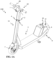
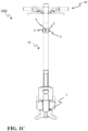
- FIGS 1A-1C illustrate schematically an electric scooter 100 with a charging adapter 2 according to an example embodiment from different viewing angles.
- Fig. 1A illustrates a perspective view of the electric scooter 100
- Fig. 1B illustrates the electric scooter 100 from a side
- Fig. 1C from the front.
- the electric scooter 100 comprises a frame 5, a front wheel support portion 7 for supporting at least one front wheel, and a rear wheel support portion 8 for supporting at least one rear wheel, wherein the front wheel support portion 7 and the rear wheel support portion 8 are coupled to the frame 5, an electric motor (not shown in Figs. 1A-1C ), and a controlling unit 21.
- the controlling unit is, preferably, configured to control the operation of the electric scooter 100, especially at least of the electric motor thereof.
- the controlling unit may comprise one or more processing units, such as processor(s), and memory, such as non-transitory or non-volatile memory storage medium, for storing instructions executable by the processing unit(s) for operating the scooter 100.
- controlling unit may comprise electrical power converter for converting and/or controlling the current being injected to the electric motor.
- the controlling unit 21 may be substantially a single unit or being distributed in more than one positions. In overall, the position of the controlling unit is not limited to any specific position, but it may reside basically anywhere in the scooter 100.
- the electric motor(s) may be arranged for rotating at least a front wheel coupled a front wheel support portion 7 and/or at least a rear wheel coupled to the rear wheel support portion 8.
- the electric motor may be a hub motor in the front and/or rear wheel.
- the electric scooter 100 comprises a chargeable battery 6 and a charging adapter 2 mounted on a headtube 10 of the electric scooter 100.
- the charging adapter 2 comprises two electrical contacts 3 (only one electrical contact is shown in Figs. 1A-1B ) on the sides of the charging adapter 2 and on the sides of the headtube, and an RFID tag 4 in front of the charging adapter 2 facing the riding direction of the scooter 100.
- the mounting height of the charging adapter 2 depends on the height of a charging interface socket of a charging station, wherein the scooter 100 is configured to be charged.
- the charging adapter 2 may be mounted on the headtube 10, for example, by glue, by fixing means, for example, by screws, or by a collar or corresponding (not shown).
- the electric scooter 100 further comprises required electronics and circuitry (not shown) needed for charging the battery 6 through the charging adapter 2.
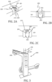
- FIGS 2A-2C illustrate schematically a charging interface socket 200 of a charging station 300 according to an example embodiment from different viewing angles.
- Fig. 2A illustrates a perspective view of the charging interface socket 200
- Fig. 2B illustrates the charging interface socket 200 from the front i.e. a direction wherefrom a light electric vehicle, for example, a scooter is configured to be pushed to the charging station
- Fig. 2C from above.
- the charging interface socket 200 is arranged in connection with the charging station, for example, to a horizontal support plate of the charging station 301 or some other suitable part of the charging station.
- the charging interface socket 200 comprises a notch 210 for receiving a headtube of a light electric vehicle and a charging adapter mounted on the headtube. It may say that the charging interface socket 200 could, for example, have a shape that substantially corresponds the letter U.
- the charging interface socket 200 further comprises, on the inner surface of the notch 210, an RFID reader 203 for a RFID tag of the light electric vehicle, a fixing mechanism 202 for holding the light electric vehicle in place in the notch 210 and in the charging station 300, and two electrical contacts 201 to be connected with electric contacts of the adapter.
- the fixing mechanism 202 comprises, in this example embodiment, two spring-tensioned contact rollers arranged at or near the mouth of the notch 210 of the socket 200.
- the electrical contacts 201 are in this example embodiment spring contacts so that the contact with the contacts of the charging adapter is easier, more reliable, and ensures electric contact in a wide range of tolerances.
- the socket 200 may comprise inside it a rubber cushion for making the insertion of the LEV to the socket 200 smoother.
- the charging interface socket 200 maybe made of plastic.
- a charging station 300 for charging light electric vehicles 100 for example, electric scooters 100 comprising a charging adapter 2 shown in FIGs 1A-1C .
- the charging station 300 comprises two chargers 302 and a plurality of charging interface sockets 200 for receiving a light electric vehicle.
Landscapes
- Engineering & Computer Science (AREA)
- Power Engineering (AREA)
- Transportation (AREA)
- Mechanical Engineering (AREA)
- Charge And Discharge Circuits For Batteries Or The Like (AREA)
- Electric Propulsion And Braking For Vehicles (AREA)
Claims (13)
- Ladeadapter, wobei der Ladeadapter (2) an einem Steuerrohr (10) eines leichten Elektrofahrzeugs (100) montierbar ist, der Ladeadapter (2) einen RFID-Tag (4), der von einem RFID-Lesegerät einer Ladestation für Elektroroller des leichten Elektrofahrzeugs (100) gelesen und erkannt werden kann, und zwei elektrische Kontakte (3) zum Empfangen von elektrischer Energie von der Ladestation für Elektroroller umfasst, dadurch gekennzeichnet, dass die beiden elektrischen Kontakte (3) an den Seiten des Steuerrohrs (10) und des RFID-Tags (4) angeordnet sind, wobei der RFID-Tag (4) so konfiguriert ist, dass er in Fahrtrichtung des leichten Elektrofahrzeugs (100) zeigt, wenn der Ladeadapter (2) am Steuerrohr (10) montiert ist.
- Ladeadapter nach Anspruch 1, wobei der RFID-Tag (4) und zwei elektrische Kontakte (3) an der Außenfläche des Ladeadapters (2) angeordnet sind.
- Ladeadapter nach Anspruch 1 oder 2, wobei die Innenfläche des Ladeadapters (2) zur Montage am Steuerrohr (10) ausgebildet ist.
- Ladeadapter nach einem der Ansprüche 1 bis 3, wobei der Ladeadapter (2) eine Form aufweist, die in der horizontalen Ebene einem Buchstaben U entspricht.
- Ladeadapter nach Anspruch 4, wobei der RFID-Tag (4) an der Spitze des u-förmigen Ladeadapters (2) angeordnet ist.
- Ladeadapter nach einem der Ansprüche 1 bis 3, wobei der Ladeadapter (2) die Form eines Querschnitts des Steuerrohrs (10) aufweist.
- Leichtes Elektrofahrzeug (100), dadurch gekennzeichnet, dass das leichte Elektrofahrzeug (100) einen Ladeadapter (2) nach einem der Ansprüche 1 bis 6 umfasst.
- Leichtes Elektrofahrzeug (100) nach Anspruch 7, wobei das leichte Elektrofahrzeug (100) ein Elektroroller ist.
- Leichtes Elektrofahrzeug (100) nach Anspruch 7 oder 8, wobei das leichte Elektrofahrzeug (100) ferner einen GPS-Tracker-Chip (21) umfasst.
- Ladeschnittstellenbuchse für eine Ladestation, wobei die Ladeschnittstellenbuchse (200) eine Aussparung (210) zur Aufnahme eines Steuerrohrs eines leichten Elektrofahrzeugs und einen RFID-Lesegerät (203), der zum Lesen und Erkennen eines RFID-Tags des leichten Elektrofahrzeugs konfiguriert ist, einen Befestigungsmechanismus (202) zum Festhalten des leichten Elektrofahrzeugs in der Aussparung (210) und zwei elektrische Kontakte (201) zum Zuführen elektrischer Energie zu einer Batterie des leichten Elektrofahrzeugs an der Innenfläche der Aussparung (210) umfasst, dadurch gekennzeichnet, dass der RFID-Lesegerät (203) am Ende der Aussparung (210) der Buchse (200) angeordnet ist, der Befestigungsmechanismus (202) an oder in der Nähe der Mündung der Aussparung (210) angeordnet ist und die elektrischen Kontakte zwischen dem RFID-Lesegerät (203) und dem Befestigungsmechanismus (202) angeordnet sind.
- Ladeschnittstellenbuchse nach Anspruch 10, wobei der Fixiermechanismus (202) zwei federgespannte Kontaktrollen umfasst, die beidseitig an oder in der Nähe der Mündung der Aussparung (210) der Ladeschnittstellenbuchse (200) angeordnet sind.
- Ladeschnittstellenbuchse nach Anspruch 10 oder 11, wobei die elektrischen Kontakte (201) federbelastete Kontakte sind.
- Ladestation zum Laden eines leichten Elektrofahrzeugs, wobei die Ladestation (300) mindestens ein Ladegerät (302) und mindestens eine Ladeschnittstellenbuchse (200) nach Anspruch 10 bis 12 für ein leichtes Elektrofahrzeug umfasst.
Priority Applications (1)
| Application Number | Priority Date | Filing Date | Title |
|---|---|---|---|
| PL21748834.5T PL4373701T3 (pl) | 2021-07-22 | 2021-07-22 | Stacja ładowania hulajnogi elektrycznej i hulajnoga elektryczna |
Applications Claiming Priority (1)
| Application Number | Priority Date | Filing Date | Title |
|---|---|---|---|
| PCT/EP2021/070496 WO2023001376A1 (en) | 2021-07-22 | 2021-07-22 | Charging station for an electric scooter and electric scooter |
Publications (3)
| Publication Number | Publication Date |
|---|---|
| EP4373701A1 EP4373701A1 (de) | 2024-05-29 |
| EP4373701B1 true EP4373701B1 (de) | 2025-07-02 |
| EP4373701C0 EP4373701C0 (de) | 2025-07-02 |
Family
ID=77155761
Family Applications (1)
| Application Number | Title | Priority Date | Filing Date |
|---|---|---|---|
| EP21748834.5A Active EP4373701B1 (de) | 2021-07-22 | 2021-07-22 | Ladestation für einen elektroroller und elektroroller |
Country Status (6)
| Country | Link |
|---|---|
| US (1) | US20250001881A1 (de) |
| EP (1) | EP4373701B1 (de) |
| CN (1) | CN118043220A (de) |
| ES (1) | ES3037381T3 (de) |
| PL (1) | PL4373701T3 (de) |
| WO (1) | WO2023001376A1 (de) |
Families Citing this family (4)
| Publication number | Priority date | Publication date | Assignee | Title |
|---|---|---|---|---|
| US11279250B2 (en) * | 2019-08-16 | 2022-03-22 | Neptune Scooters | Electric scooter docking stations |
| US20230278443A1 (en) * | 2021-12-23 | 2023-09-07 | Kuhmute Inc. | System for use in docking and charging micro-mobility electric vehicles |
| SE2351158A1 (en) * | 2023-10-09 | 2025-02-18 | Standab Ab | Light electric vehicle parking and charging system |
| USD1114680S1 (en) * | 2023-10-25 | 2026-02-24 | Shanghai Magic Wheels Sporting Goods Co., Ltd. | Battery part for scooter |
Family Cites Families (3)
| Publication number | Priority date | Publication date | Assignee | Title |
|---|---|---|---|---|
| WO2017217929A1 (en) * | 2016-06-16 | 2017-12-21 | Neuron Mobility Pte Ltd. | Docking station for motorised vehicles |
| WO2020023933A2 (en) * | 2018-07-26 | 2020-01-30 | Swiftmile, Inc. | Light electric vehicle parking and charging stations and smart charging systems for the vehicle batteries |
| US12508926B2 (en) * | 2019-10-23 | 2025-12-30 | Acton, Inc. | Docking and recharging system for battery powered personal mobility vehicles |
-
2021
- 2021-07-22 ES ES21748834T patent/ES3037381T3/es active Active
- 2021-07-22 CN CN202180102195.9A patent/CN118043220A/zh active Pending
- 2021-07-22 PL PL21748834.5T patent/PL4373701T3/pl unknown
- 2021-07-22 EP EP21748834.5A patent/EP4373701B1/de active Active
- 2021-07-22 WO PCT/EP2021/070496 patent/WO2023001376A1/en not_active Ceased
- 2021-07-22 US US18/580,369 patent/US20250001881A1/en active Pending
Also Published As
| Publication number | Publication date |
|---|---|
| US20250001881A1 (en) | 2025-01-02 |
| PL4373701T3 (pl) | 2026-03-09 |
| CN118043220A (zh) | 2024-05-14 |
| EP4373701C0 (de) | 2025-07-02 |
| EP4373701A1 (de) | 2024-05-29 |
| ES3037381T3 (en) | 2025-10-01 |
| WO2023001376A1 (en) | 2023-01-26 |
Similar Documents
| Publication | Publication Date | Title |
|---|---|---|
| EP4373701B1 (de) | Ladestation für einen elektroroller und elektroroller | |
| JP3786392B2 (ja) | 電動車両用充電装置 | |
| EP3489867A1 (de) | System, server und verfahren zum entsendung eines selbstfahrenden fahrzeugs | |
| US9676263B2 (en) | Electrically powered cycles and automatic storage system for such cycles | |
| JP2008537520A (ja) | 自転車自動保管システムおよびこのシステムのための自転車 | |
| JP7149297B2 (ja) | 充電装置の作動方法 | |
| EP3793060B1 (de) | System zur drahtlosen stromversorgung und vorrichtung zur drahtlosen stromversorgung | |
| KR20210155039A (ko) | 이동식 전기차 충전소 운용 시스템 및 방법과 이를 위한 컴퓨터 프로그램 | |
| US11413977B2 (en) | Charging assembly for electric vehicle | |
| US20190118666A1 (en) | Method for operating a motor vehicle and motor vehicle | |
| KR20110001362U (ko) | 전기 자전거 거치장치 | |
| KR102006327B1 (ko) | 전기 자전거 충전시스템 | |
| US20230256838A1 (en) | Method for performing an electrical charging process | |
| KR20190108753A (ko) | 전기자동차의 배터리 교체방법 및 전기자동차 | |
| CN113904065A (zh) | 可堆叠电池总成和使用方法 | |
| US11828609B2 (en) | Control device of vehicle and vehicle control system | |
| KR102569286B1 (ko) | 전기차 충전용 커넥터 및 전기차 충전 시스템 | |
| EP3305580A1 (de) | Primäres fahrzeug mit einer traktionsbatterie und verfahren zur steuerung eines ladevorgangs einer traktionsbatterie eines sekundären fahrzeugs | |
| KR20220026731A (ko) | 주행 중 전기차 충전 장치 및 이의 연결 방법 | |
| EP4170858A1 (de) | Vorrichtung zur übertragung von elektrischer ladung | |
| NL2030621B1 (nl) | Laadsysteem voor elektrisch aangedreven voertuigen | |
| US20220379983A1 (en) | Connection System for Connecting a Small Vehicle to a Base Station | |
| US10960780B2 (en) | Charging device for supplying electrical charging energy | |
| US20210155106A1 (en) | Method for recharging an electrical energy storage device storing electrical energy of a plurality of vehicles | |
| US20250023371A1 (en) | Pushable transport cart and pushable transport cart system |
Legal Events
| Date | Code | Title | Description |
|---|---|---|---|
| STAA | Information on the status of an ep patent application or granted ep patent |
Free format text: STATUS: UNKNOWN |
|
| STAA | Information on the status of an ep patent application or granted ep patent |
Free format text: STATUS: THE INTERNATIONAL PUBLICATION HAS BEEN MADE |
|
| PUAI | Public reference made under article 153(3) epc to a published international application that has entered the european phase |
Free format text: ORIGINAL CODE: 0009012 |
|
| STAA | Information on the status of an ep patent application or granted ep patent |
Free format text: STATUS: REQUEST FOR EXAMINATION WAS MADE |
|
| 17P | Request for examination filed |
Effective date: 20240205 |
|
| AK | Designated contracting states |
Kind code of ref document: A1 Designated state(s): AL AT BE BG CH CY CZ DE DK EE ES FI FR GB GR HR HU IE IS IT LI LT LU LV MC MK MT NL NO PL PT RO RS SE SI SK SM TR |
|
| DAV | Request for validation of the european patent (deleted) | ||
| DAX | Request for extension of the european patent (deleted) | ||
| GRAP | Despatch of communication of intention to grant a patent |
Free format text: ORIGINAL CODE: EPIDOSNIGR1 |
|
| STAA | Information on the status of an ep patent application or granted ep patent |
Free format text: STATUS: GRANT OF PATENT IS INTENDED |
|
| RIC1 | Information provided on ipc code assigned before grant |
Ipc: B62K 3/00 20060101ALI20250204BHEP Ipc: B60L 53/31 20190101ALI20250204BHEP Ipc: B60L 53/65 20190101ALI20250204BHEP Ipc: B60L 53/16 20190101AFI20250204BHEP Ipc: B62H 3/00 20060101ALI20250204BHEP |
|
| INTG | Intention to grant announced |
Effective date: 20250217 |
|
| GRAS | Grant fee paid |
Free format text: ORIGINAL CODE: EPIDOSNIGR3 |
|
| GRAA | (expected) grant |
Free format text: ORIGINAL CODE: 0009210 |
|
| STAA | Information on the status of an ep patent application or granted ep patent |
Free format text: STATUS: THE PATENT HAS BEEN GRANTED |
|
| AK | Designated contracting states |
Kind code of ref document: B1 Designated state(s): AL AT BE BG CH CY CZ DE DK EE ES FI FR GB GR HR HU IE IS IT LI LT LU LV MC MK MT NL NO PL PT RO RS SE SI SK SM TR |
|
| REG | Reference to a national code |
Ref country code: GB Ref legal event code: FG4D |
|
| REG | Reference to a national code |
Ref country code: CH Ref legal event code: EP |
|
| REG | Reference to a national code |
Ref country code: DE Ref legal event code: R096 Ref document number: 602021033400 Country of ref document: DE |
|
| REG | Reference to a national code |
Ref country code: IE Ref legal event code: FG4D |
|
| U01 | Request for unitary effect filed |
Effective date: 20250730 |
|
| U07 | Unitary effect registered |
Designated state(s): AT BE BG DE DK EE FI FR IT LT LU LV MT NL PT RO SE SI Effective date: 20250807 |
|
| REG | Reference to a national code |
Ref country code: ES Ref legal event code: FG2A Ref document number: 3037381 Country of ref document: ES Kind code of ref document: T3 Effective date: 20251001 |
|
| U20 | Renewal fee for the european patent with unitary effect paid |
Year of fee payment: 5 Effective date: 20250904 |
|
| REG | Reference to a national code |
Ref country code: CH Ref legal event code: U11 Free format text: ST27 STATUS EVENT CODE: U-0-0-U10-U11 (AS PROVIDED BY THE NATIONAL OFFICE) Effective date: 20251021 |
|
| PG25 | Lapsed in a contracting state [announced via postgrant information from national office to epo] |
Ref country code: IS Free format text: LAPSE BECAUSE OF FAILURE TO SUBMIT A TRANSLATION OF THE DESCRIPTION OR TO PAY THE FEE WITHIN THE PRESCRIBED TIME-LIMIT Effective date: 20251102 |
|
| PGFP | Annual fee paid to national office [announced via postgrant information from national office to epo] |
Ref country code: GB Payment date: 20251020 Year of fee payment: 5 |
|
| PGFP | Annual fee paid to national office [announced via postgrant information from national office to epo] |
Ref country code: NO Payment date: 20250922 Year of fee payment: 5 |
|
| PG25 | Lapsed in a contracting state [announced via postgrant information from national office to epo] |
Ref country code: HR Free format text: LAPSE BECAUSE OF FAILURE TO SUBMIT A TRANSLATION OF THE DESCRIPTION OR TO PAY THE FEE WITHIN THE PRESCRIBED TIME-LIMIT Effective date: 20250702 |
|
| PG25 | Lapsed in a contracting state [announced via postgrant information from national office to epo] |
Ref country code: GR Free format text: LAPSE BECAUSE OF FAILURE TO SUBMIT A TRANSLATION OF THE DESCRIPTION OR TO PAY THE FEE WITHIN THE PRESCRIBED TIME-LIMIT Effective date: 20251003 |
|
| PGFP | Annual fee paid to national office [announced via postgrant information from national office to epo] |
Ref country code: CH Payment date: 20251021 Year of fee payment: 5 |
|
| PG25 | Lapsed in a contracting state [announced via postgrant information from national office to epo] |
Ref country code: CZ Free format text: LAPSE BECAUSE OF FAILURE TO SUBMIT A TRANSLATION OF THE DESCRIPTION OR TO PAY THE FEE WITHIN THE PRESCRIBED TIME-LIMIT Effective date: 20250702 |
|
| PG25 | Lapsed in a contracting state [announced via postgrant information from national office to epo] |
Ref country code: RS Free format text: LAPSE BECAUSE OF FAILURE TO SUBMIT A TRANSLATION OF THE DESCRIPTION OR TO PAY THE FEE WITHIN THE PRESCRIBED TIME-LIMIT Effective date: 20251002 |
|
| PGFP | Annual fee paid to national office [announced via postgrant information from national office to epo] |
Ref country code: ES Payment date: 20251028 Year of fee payment: 5 |
|
| PG25 | Lapsed in a contracting state [announced via postgrant information from national office to epo] |
Ref country code: SM Free format text: LAPSE BECAUSE OF FAILURE TO SUBMIT A TRANSLATION OF THE DESCRIPTION OR TO PAY THE FEE WITHIN THE PRESCRIBED TIME-LIMIT Effective date: 20250702 |