EP4373374B1 - Handgeführte bodenbehandlungsmaschine - Google Patents
Handgeführte bodenbehandlungsmaschine Download PDFInfo
- Publication number
- EP4373374B1 EP4373374B1 EP22748060.5A EP22748060A EP4373374B1 EP 4373374 B1 EP4373374 B1 EP 4373374B1 EP 22748060 A EP22748060 A EP 22748060A EP 4373374 B1 EP4373374 B1 EP 4373374B1
- Authority
- EP
- European Patent Office
- Prior art keywords
- machine
- base portion
- guide wheel
- drive
- wheel means
- Prior art date
- Legal status (The legal status is an assumption and is not a legal conclusion. Google has not performed a legal analysis and makes no representation as to the accuracy of the status listed.)
- Active
Links
Images


Classifications
-
- A—HUMAN NECESSITIES
- A47—FURNITURE; DOMESTIC ARTICLES OR APPLIANCES; COFFEE MILLS; SPICE MILLS; SUCTION CLEANERS IN GENERAL
- A47L—DOMESTIC WASHING OR CLEANING; SUCTION CLEANERS IN GENERAL
- A47L11/00—Machines for cleaning floors, carpets, furniture, walls, or wall coverings
- A47L11/02—Floor surfacing or polishing machines
- A47L11/10—Floor surfacing or polishing machines motor-driven
- A47L11/14—Floor surfacing or polishing machines motor-driven with rotating tools
- A47L11/16—Floor surfacing or polishing machines motor-driven with rotating tools the tools being disc brushes
-
- A—HUMAN NECESSITIES
- A47—FURNITURE; DOMESTIC ARTICLES OR APPLIANCES; COFFEE MILLS; SPICE MILLS; SUCTION CLEANERS IN GENERAL
- A47L—DOMESTIC WASHING OR CLEANING; SUCTION CLEANERS IN GENERAL
- A47L11/00—Machines for cleaning floors, carpets, furniture, walls, or wall coverings
- A47L11/40—Parts or details of machines not provided for in groups A47L11/02 - A47L11/38, or not restricted to one of these groups, e.g. handles, arrangements of switches, skirts, buffers, levers
- A47L11/4036—Parts or details of the surface treating tools
- A47L11/4038—Disk shaped surface treating tools
-
- A—HUMAN NECESSITIES
- A47—FURNITURE; DOMESTIC ARTICLES OR APPLIANCES; COFFEE MILLS; SPICE MILLS; SUCTION CLEANERS IN GENERAL
- A47L—DOMESTIC WASHING OR CLEANING; SUCTION CLEANERS IN GENERAL
- A47L11/00—Machines for cleaning floors, carpets, furniture, walls, or wall coverings
- A47L11/28—Floor-scrubbing machines, motor-driven
- A47L11/282—Floor-scrubbing machines, motor-driven having rotary tools
- A47L11/283—Floor-scrubbing machines, motor-driven having rotary tools the tools being disc brushes
-
- A—HUMAN NECESSITIES
- A47—FURNITURE; DOMESTIC ARTICLES OR APPLIANCES; COFFEE MILLS; SPICE MILLS; SUCTION CLEANERS IN GENERAL
- A47L—DOMESTIC WASHING OR CLEANING; SUCTION CLEANERS IN GENERAL
- A47L11/00—Machines for cleaning floors, carpets, furniture, walls, or wall coverings
- A47L11/29—Floor-scrubbing machines characterised by means for taking-up dirty liquid
- A47L11/292—Floor-scrubbing machines characterised by means for taking-up dirty liquid having rotary tools
- A47L11/293—Floor-scrubbing machines characterised by means for taking-up dirty liquid having rotary tools the tools being disc brushes
-
- A—HUMAN NECESSITIES
- A47—FURNITURE; DOMESTIC ARTICLES OR APPLIANCES; COFFEE MILLS; SPICE MILLS; SUCTION CLEANERS IN GENERAL
- A47L—DOMESTIC WASHING OR CLEANING; SUCTION CLEANERS IN GENERAL
- A47L11/00—Machines for cleaning floors, carpets, furniture, walls, or wall coverings
- A47L11/29—Floor-scrubbing machines characterised by means for taking-up dirty liquid
- A47L11/30—Floor-scrubbing machines characterised by means for taking-up dirty liquid by suction
- A47L11/302—Floor-scrubbing machines characterised by means for taking-up dirty liquid by suction having rotary tools
-
- A—HUMAN NECESSITIES
- A47—FURNITURE; DOMESTIC ARTICLES OR APPLIANCES; COFFEE MILLS; SPICE MILLS; SUCTION CLEANERS IN GENERAL
- A47L—DOMESTIC WASHING OR CLEANING; SUCTION CLEANERS IN GENERAL
- A47L11/00—Machines for cleaning floors, carpets, furniture, walls, or wall coverings
- A47L11/40—Parts or details of machines not provided for in groups A47L11/02 - A47L11/38, or not restricted to one of these groups, e.g. handles, arrangements of switches, skirts, buffers, levers
- A47L11/4013—Contaminants collecting devices, i.e. hoppers, tanks or the like
- A47L11/4016—Contaminants collecting devices, i.e. hoppers, tanks or the like specially adapted for collecting fluids
-
- A—HUMAN NECESSITIES
- A47—FURNITURE; DOMESTIC ARTICLES OR APPLIANCES; COFFEE MILLS; SPICE MILLS; SUCTION CLEANERS IN GENERAL
- A47L—DOMESTIC WASHING OR CLEANING; SUCTION CLEANERS IN GENERAL
- A47L11/00—Machines for cleaning floors, carpets, furniture, walls, or wall coverings
- A47L11/40—Parts or details of machines not provided for in groups A47L11/02 - A47L11/38, or not restricted to one of these groups, e.g. handles, arrangements of switches, skirts, buffers, levers
- A47L11/4063—Driving means; Transmission means therefor
-
- A—HUMAN NECESSITIES
- A47—FURNITURE; DOMESTIC ARTICLES OR APPLIANCES; COFFEE MILLS; SPICE MILLS; SUCTION CLEANERS IN GENERAL
- A47L—DOMESTIC WASHING OR CLEANING; SUCTION CLEANERS IN GENERAL
- A47L11/00—Machines for cleaning floors, carpets, furniture, walls, or wall coverings
- A47L11/40—Parts or details of machines not provided for in groups A47L11/02 - A47L11/38, or not restricted to one of these groups, e.g. handles, arrangements of switches, skirts, buffers, levers
- A47L11/4072—Arrangement of castors or wheels
Definitions
- the present invention relates to the field of floor treatment machines for scrubbing, polishing, sanding or burnishing floors.
- floor treatment machines for scrubbing, polishing, sanding or burnishing floors.
- one or more driven rotatable work heads (such as scrubbing brushes) are provided for agitating the floor surface.
- the invention relates to a walk-behind machine provided with a handle for steering and guiding the machine as it travels over a floor surface.
- EP-A-3031378 discloses a walk-behind wet floor scrubber having two side-by-side work heads, each comprising disc-shaped floor brushes. There is a trailing squeegee and associated suction drive and reservoir for collecting liquid from the floor surface.
- the suction drive is disposed on a handle portion of the machine, along with a clean water reservoir for feeding a cleaning-liquid dispenser.
- the handle has dual pivot axes permitting up/down handle movement as well as side-to-side, which aids in making the machine highly manoeuvrable on the floor surface.
- the brushes support the entire weight of the machine and contra-rotate with respect to one another. By angling the axes of rotation of the brushes slightly away from the vertical (to provide a brush anhedral or dihedral tilt), the bushes can be induced to provide forward propulsion whenever the machine is operational.
- the wheel takes some weight of the machine and may be directly steered by the handle portion acting on a wheel fork.
- the guide wheel prevents lateral or directional drift of the machine under propulsion and provides wheels steering of the machine. This provides excellent direction stability as well as the ability to turn in tight arcs by yawing of the machine around the guide wheel.
- a hand guided, walk-behind floor treatment machine is also already known from US-A-2021076894 .
- a problem with machines which rely upon propulsion by counter-rotating discs is that the amount of propulsive force is coupled to the rotational speed of the brushes, and thus is felt whenever the scrubbing action takes place.
- the machine can seem to runaway from the operator, and the user may need to drag the machine back to re-treat persistent dirty floor areas, which can be inconvenient and tiresome.
- the motor traction drive may be provided with a motor controller which permits the drive to be activated or de-activated.
- the motor controller is preferably configured to permit motor traction drive control independent of the operation of the work head drive means.
- the motor controller may be configured to provide traction drive speed control.
- the motor controller speed may be adapted to permit continuously variable speed control, or stepped speed control, or the adoption of discrete single speed settings.
- a predetermined preferred speed may be provided as a setting.
- Several such pre-determined settings may be provided. These may be selected as suitable for particular floor types (wood, tile, concrete etc), or for treatment types (such as for polishing, light scrubbing, or heavy scrubbing), or to adapt for different brush stiffnesses.
- the motor controller may be configured to provide a reverse drive of the guide wheel means so that the machine may be propelled backwards.
- the guide wheel means may comprise one or more wheels.
- the wheel means may comprise one or more rollers, one or more balls, or caterpillar tracks. In a preferred arrangement there may be a single guide wheel.
- the guide wheel means may have a fixed transverse axis of rotation with respect to the base portion, so that the base portion turns correspondingly left or right as the wheel means is yaw steered.
- the motor traction drive may be carried by the handle portion, or the base portion, or may be associated with and carried by the guide wheel. In a preferred arrangement there is a wheel hub drive incorporated into at least one wheel of the guide wheel means.
- the motor traction drive will typically be an electric device, with power supplied by batteries or cells, or from electrical mains power supply.
- a user interface may be provided which includes controls for actuation and operation of the motor traction drive.
- the interface is preferably disposed at an upper end region of the handle portion.
- the interface may be in the form of a panel.
- the user interface may be provided with user-operable controls adapted to permit user-selective on/off actuation of the motor traction drive, and optionally user selective speed control of the motor traction drive.
- the controls may be adapted to permit selective operation so as to provide forward drive in the working direction or reverse drive in the opposite direction.
- the lower region of the handle portion may be attached to the wheel means via the articulated joint and which permits up/down pivoting of the handle about the joint.
- the articulated joint arrangement may also permit side-to-side pivoting of the handle about the joint.
- the up/down pivot of the articulated joint may be provided at a pivot coaxial with the wheel means axis of rotation.
- the side-to-side pivot of the articulated joint may be provided at a location vertically spaced apart from the up/down pivot.
- the articulated joint may comprise a yoke or fork which accommodates a wheel, roller or ball of the guide wheel means, which yoke pivots about the wheel rotation axis.
- the side-to-side pivot may be disposed on an upper bridging portion of the yoke.
- the handle portion's articulated joint arrangement may be configured to permit fore/aft and side to side pivoting of the handle portion with respect to the base portion or guide wheel means.
- the joint arrangement may be configured to permit the transfer of steering torque applied by a user to the handle portion to the guide wheel means or base portion, thereby to permit yaw steering of the guide wheel means with the base portion left or right to vary the direction of travel.
- a suitable joint arrangement is a universal joint (or cardan joint).
- the cardan joint may be configured to act on the guide wheels means to yaw steer the guide wheel means along with the base portion.
- the cardan joint may comprise a side-to-side pivot which comprises a U-section bracket rotated 90 degrees with respect to a yoke which receives a lower end of the handle portion.
- a flexible strut member via which the handle portion is connected to the base portion or guide wheel means.
- the strut as a generally vertical disposition until the handle if pivoted away from the vertical by bending of the strut member. This permits the handle portion to pivot about the strut member forwards or backwards and left or right (from side to side).
- the strut member also permits transmission of torque from the handle portion to the guide wheel means or base portion, so as to steer the base portion and/or guide wheel means.
- the flexible strut member may comprise an elongate tubular member.
- the flexible tubular member may be as described in WO2020234904A1 (Moro & Moro ).
- the weight of the machine is typically supported partially by the guide wheel means and partially by the work head(s), and any other ancillary supports such as secondary rollers or wheels.
- the base unit is substantially entirely supported by the work head(s), and the guide wheels means supports the handle portion (and any associated attachments, such as control panel, cleaning liquid reservoir and dirty water tank).
- Any squeegee suction unit is usually self-supporting on rollers or wheels, but trails behind the work heads.
- the handle portion may support a reservoir for floor cleaning liquid.
- the machine may be provided with a suction drive and an associated squeegee collection apparatus. This will usually be arranged to be trailed behind the work head(s) to collect and store used cleaning fluid lifted from the floor in a dirty water tank.
- the dirty water tank is supported by the handle portion.
- the guide wheel When the handle portion is connected to the guide wheel, the guide wheel will take the weight of the handle portion and any supported items such as the cleaning liquid reservoir or the dirty water tank. This can prevent overloading of the work heads, whilst also ensuring that a good contact is made between the guide wheel and the floor.
- the handle portion is preferably lockable in a substantially vertical parked orientation in which the pivoting of the handle portion with respect to the base portion is disabled.
- the articulated joint arrangement can be selectively immobilised in the vertical parked orientation, such as by engagement of a tooth and detent feature.
- the guide wheel means may be coupled to the base portion by a linkage arrangement which permits vertical travel of the base portion and associated work head or heads with respect to the guide wheel means.
- the linkage arrangement provides may provide transverse constraint to limit or prevent yawing of the base portion with respect to the guide wheel means, so that when the guide wheel means is yawed the base portion yaws with it, and vice versa.
- the linkage arrangement may comprise a pitch pivotal connection between the base portion and the guide wheel means.
- the pitch pivotal connection is coaxial with the transverse axis of rotation of the guide wheel means. Said pitch pivotal connection permits the vertical travel of the base portion with respect to the wheel means.
- Said one or more rotatable work head may support the base portion on the floor surface with the linkage arrangement permitting limited floating vertical travel of the work head(s) with respect to the guide wheel means.
- the floor treatment machine may be configured so that the base portion and associated work head or heads are provided at a front region of the machine.
- the guide wheel means may be disposed aft of the work head or heads and base portion.
- the linkage arrangement may act between the guide wheel means and base portion, and is preferably disposed generally centrally with respect to the work head or heads.
- the drive means preferably comprises one or more electric motors carried by the base portion and coupled to the work head or heads.
- a single motor can drive multiple work heads (via a suitable transmission of belts, gears or chains), or each motor can directly drive an associated work head.
- the motors or transmission may be configured and/or controlled to cause the work heads to counter rotate with respect to one another, which provides a balanced cleaning effect.
- a distal end of the handle portion may conveniently be provided with a transversely oriented handlebar for the user to grip with a hand on each side of the bar.
- the machine is a wet scrubbing machine. It may be provided with a cleaning fluid reservoir and cleaning fluid delivery outlet.
- a squeegee liquid collector is preferably provided which is coupled to the machine by a trailing linkage.
- the linkage may permit up/down travel of the squeegee collector with respect to the wheels means.
- the trailing linkage is preferably pivotably coupled to the wheel means co-axially with the transverse axis of the wheel means.
- the machine may be provided with a squeegee suction drive and dirty liquid collection reservoir.
- the handlebar may be provided with a speed control lever or twist grip and cleaning fluid dispensing actuator.
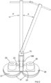
- a floor scrubber dryer machine in accordance with the present invention is shown generally as 10.
- the machine comprises an elongate rectangular section handle portion 12.
- the handle portion 12 comprises a top end region and a bottom end region.
- a handlebar 13 is transversely mounted via a bore at the top end region of the handle portion 12.
- a control unit (not shown) is also provided at the top end region which includes an off/on toggle switch, lever or trigger for the machine. During use the user walks behind the machine and guides it over the floor surface to be cleaned using the handlebar 13.
- the bottom end region of the handle portion 12 is pivotally attached between upstanding ear portions of a U-section mounting bracket 14.
- the pivot is oriented fore-aft to enable side-to-side rotation of the handle portion relative to the bracket 14 about a pivot axis 15, as shown in the arrows A, A' of Figure 3 .
- the axis 15 is substantially perpendicular to the length of the handle portion 12 and permits the handle to be swung transversely from side to side about the bottom end region.
- the bracket 14 has a lower region which is configured as a fork or yoke 17 formed by two spaced apart downwardly extending cheek plates.
- a guide wheel 18 is located between the cheek plates and mounted for rotation about an axle 19, as shown in Figure 2 .
- the axle provides a pivot which permits the top end region of the handle portion to be pivoted forward/backwards, up/down through an arc V around the transverse axis 19A provided by the axle 19.
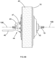
- FIG. 5A the wheel is shown generally as 18.
- a cylindrical solid rubber tyre 40 extending around the periphery of the wheel.
- the tyre may be provided with a moulded tread pattern which assists gripping of floor surfaces when the machine is in use.
- a central region of the wheel is provided with a generally dish shaped housing 41 for an electric hub motor (not visible).
- the dish periphery is provided with a series of circumferentially spaced mounting rivets 42
- a central bushing 43 is provided around the axle 19, so as to permit rotation of the wheel and hub around the fixed axle 19.
- the hub motor is of conventional construction so is not described in detail herein. A wide range of hub motors are commercially available.
- the hub On the opposite side of the guide wheel (see figure 5B ) is another hub arrangement 44 which includes a bushing 45.
- the hub receives a wiring harness 46.
- the harness includes power cables which are connected to a rechargeable battery (not shown) carried by the machine.
- the hub also includes a sensor 47 which communicates with a speed controller (located in the upper handle portion (not visible) near the cross bar 13). The sensor detects rotation of the hub and wheel relative to the axle.
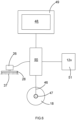
- a schematic diagram shows a user interface panel 49 with a touch screen 48.
- the panel communicates with a motor controller 50 which includes a programmable data processing unit (not shown).
- the controller receives and communicates with the wiring harness 46 of the hub drive wheel, which along with power lines also includes a signal from the hub sensor 47.
- a battery 51 for powering the hub motor is connected to the controller.
- the controller also controls the work head motor(s) 26 which drive the scrubbing brushes 37.
- the primary controls are on/off and speed control. These can in accordance with the present invention be carried out independently of the traction drive or drive speed.
- Various functions are accessible to the user via the interface touch screen and are effected by transmission of appropriate signals to the data processing unit.
- the hub motor can be activated by pressing a start tab (so as to rotate the wheel 18).
- a stop tab kills the motor.
- the sensor 47 provides rate of rotation information and is used to provide feedback so as to maintain a desired rate of rotation.
- the user interface panel would be carried at an upper region of the handle portion 12.
- the motor controller would be physically integrated into the interface panel housing so as to protect it from moisture and dirt released by the cleaning or scrubbing process.
- Various touch tabs may be provided to permit selection of modes corresponding to various combinations of the floor properties (wood, carpet, vinyl, tiles, paving slabs, concrete and corresponding work head brush attachments).
- the motor traction speed may be adjusted to preferred settings associated with the floor and brush responses.
- the panel and the controller can be configured to provide integrated control of the work head drive motors (one 26 indicated in figure 6 ), so as to adjust work head rotation speed in each mode, as well as the desired traction drive speeds. For example, a slow traction drive speed with high work head rotation speeds can be used for tough scrubbing jobs.
- the work head rotation is not tied to an associated propulsive speed when using a wheeled traction drive.
- Speed increase and decrease tabs on the panel allow fine tuning of the traction speed by the user (if required). The incremental speed increase/decrease can be gradual or stepped.
- the wheel 18 is mounted to enable rotation about a single transverse axis and is otherwise fixed in position relative to the base of the machine.
- the wheel 18 may be configured to lean either left or right into a turn as a user manoeuvres the machine 18 around the floor surface. This can improve the handling of the machine 10.
- the same leaning could apply to other wheel means such as rollers or balls.
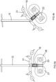
- a pair of elongate, forwardly extending, spaced apart mounting struts 21 are pivotally attached at rear end regions thereof to opposite respective sides the wheel axle 19 projecting from either side of the wheel 18. Front end regions of each strut are attached to a pair of upstanding, spaced apart generally triangular brackets 22 formed on a rectangular work base plate 23. The attachment is made via a pivot connection 24 having a transverse axis of rotation.
- the base portion supports thereon two electric motors side by side which are a left scrubber electric motor 25 and a right scrubber electric motor 26.
- a left scrubber brush 27 and a right scrubber brush 28 are attached under the base portion 23 to depending respective rotors (not shown) of the electric motors.
- the left scrubber and right scrubber are mounted to the rotors using conventional means such as a hub or chuck (not shown).
- Each scrubber brush 27, 28 comprises a disc shaped base portion 29, and an annular array of fibre brushes 30, fixed an underside of the base portion.
- the scrubber brushes are arranged to enable rotation in opposite directions and about parallel vertical axes as shown in Figure 1 , which can provide forward or rearward propulsion
- the collector 30 comprises an elongate lenticular form collector arm 31.
- a forward collector blade 32 and a rear collector blade 33 are mounted below the collector arm 31 such that both the forward blade 32 and rear blade 33 are able to be in contact with a floor when the machine 10 is in normal use.
- the collector blades 32, 33 are made of an elastomeric material, as is conventional.
- the squeegee interior (chamber 34) defined between the forward and rear blades is in fluid communication with a suction drive (not shown) which may be mounted on the handle 12 or the base portion 23 so as to entrain and draw-up wastewater that has passed through the scrubber brushes. Waste water drawn-up from the suction chamber 34 is stored in a tank (not shown).
- the suction drive and tank may be positioned above the scrubber mount 11, or on the handle portion 12, or at another convenient location on the machine 10.
- a left rear wheel assembly 35 and a right rear wheel assembly 36 are both mounted to the collector arm 31 and projecting rearwardly and co-terminously.
- Each rear wheel assembly comprises a rear castor wheel.
- the squeegee collector is attached to the wheel axis 19 by a pair of transversely spaced apart rearwardly extending struts 38, so that the collector can pivot up/down around the wheel's axis.
- the squeegee collector can thus be folded up or down for storage. Furthermore, the collector can, when in use, follow floor undulations without losing suction as the machine move forwards.
- Figures 4a-4d show various configurations of the handle portion 12, the base portion 23 and the wheel yoke 17.
- Figure 4a shows a configuration in which the handle portion 12 in the left-to-right position and at an angle with the floor surface.
- the configuration of Figure 4a is similar to that shown in Figure 1 .
- Figure 4b shows a configuration in which the handle portion 12 has been rotated such that the handlebar 13 has moved to the left.
- Figure 4b represents a configuration where a user is turning the machine 10 to the left.
- Figure 4c shows a configuration in which the handle portion 12 is upright such that the handlebar 13 is parallel with the floor surface. The handle portion 12 has then been rotated such that the handlebar 13 has moved the left.
- Figure 4d shows a configuration in which the handle portion 2 has been rotated such that the handlebar 13 is now positioned forwards of the scrubbers 27, 28.
- Machines in accordance with the present invention relate to the field of floor treatment machines for scrubbing, polishing, sanding or burnishing floors, and in particular machines in which one or more driven rotatable work heads (such as scrubbing brushes) are provided for agitating the floor surface.
- driven rotatable work heads such as scrubbing brushes
- the disclosure provides a hand guided, walk-behind floor treatment machine comprising: a base portion provided with and supported by at least one rotatable work head for treating the floor, drive means for rotating the work head with respect to the base portion, guide wheel means for supporting the handle portion and/or base portion on the floor, the guide wheel means having a substantially transverse axis of rotation with respect to the base portion so as to permit machine travel over the floor in a working direction, a handle portion for steering or guiding the machine in the working direction of travel, a lower region of which handle portion is provided with an articulated joint arrangement which permits pivoting of the handle portion with respect to the base portion during machine operation, the handle portion lower region being connected to the guide wheel means or base portion so as to permit steering by manipulation of an upper region of the handle, wherein a motor traction drive is provided for driving the guide wheel means so as to permit self-propulsion of the machine over the floor and a motor controller for controlling the operation of the motor traction drive.
- the motor controller permits the traction drive to be activated or de-activated.
- the motor controller may be configured to permit motor traction drive control independent of the operation of the work head drive means.
- the motor controller is configured to provide traction drive speed control.
- the motor controller is adapted to permit continuously variable speed control, and/or stepped incremental speed control, and/or the adoption of one of a plurality of discrete single speed settings.
- the motor controller may be configured to provide a user-selectable reverse drive mode of the guide wheel means so that the machine may be propelled backwards.
Landscapes
- Handcart (AREA)
- Harvester Elements (AREA)
- Soil Working Implements (AREA)
Claims (21)
- Handgeführte Bodenbehandlungsmaschine, die Folgendes umfasst:einen Sockelteil (23), der mit mindestens einem drehbaren Arbeitskopf (37) zum Behandeln des Bodens versehen ist und davon getragen wird,ein Antriebsmittel (26) zum Drehen des Arbeitskopfes in Bezug auf den Sockelteil,ein Führungsradmittel (18) zum Tragen des Griffteils und/oder des Sockelteils am Boden, wobei das Führungsradmittel eine in Bezug auf den Sockelteil im Wesentlichen quer verlaufende Rotationsachse aufweist, so dass eine Bewegung der Maschine über den Boden in einer Arbeitsrichtung möglich ist,einen Griffteil (12) zum Steuern oder Führen der Maschine in der Arbeitsfahrtrichtung,wobei ein unterer Bereich des Griffteils mit einer Drehgelenkanordnung versehen ist,die bei Betrieb der Maschine ein Schwenken des Griffteils in Bezug auf den Sockelteil ermöglicht, wobei der untere Bereich des Griffteils mit dem Führungsradmittel oder dem Sockelteil verbunden ist, so dass ein Steuern durch Betätigen eines oberen Bereichs des Griffs möglich ist,wobei zum Antreiben des Führungsradmittels ein motorisierter Fahrantrieb vorgesehen ist, so dass ein Eigenantrieb der Maschine auf dem Boden möglich ist, und zum Steuern des Betriebs des motorisierten Fahrantriebs eine Motorsteuerung vorgesehen ist,wobei die Drehgelenkanordnung so ausgelegt ist, dass sie in Bezug auf den Sockelteil ein Schwenken des Griffteils nach vorn/hinten und von Seite zu Seite ermöglicht, undwobei die Gelenkanordnung auch die Übertragung eines von einem Benutzer auf den oberen Griffteil ausgeübten Steuermoments auf das Führungsradmittel oder den Sockelteil ermöglicht, wodurch eine Giersteuerung des Führungsradmittels nach links oder rechts möglich ist.
- Maschine nach Anspruch 1, wobei die Gelenkanordnung ein Kardangelenk umfasst, das so konfiguriert ist, dass es so auf das Führungsradmittel einwirkt, dass dieses zusammen mit dem Sockelteil, mit dem es verbunden ist, giergesteuert wird.
- Maschine nach Anspruch 1 oder 2, wobei die Motorsteuerung ein Aktivieren oder Deaktivieren des Fahrantriebs ermöglicht.
- Maschine nach einem der Ansprüche 1 bis 3, wobei die Motorsteuerung so konfiguriert ist, dass sie eine vom Betrieb der Arbeitskopfantriebsmittel unabhängige Steuerung des motorisierten Fahrantriebs ermöglicht.
- Maschine nach einem der vorhergehenden Ansprüche, wobei die Motorsteuerung so konfiguriert ist, dass sie für eine Drehzahlregelung des Fahrantriebs sorgt.
- Maschine nach einem der vorhergehenden Ansprüche, wobei die Motorsteuerung so ausgelegt ist, dass sie eine kontinuierlich stufenlose Drehzahlregelung und/oder eine stufenweise inkrementelle Drehzahlregelung und/oder die Übernahme einer von mehreren diskreten einzelnen Drehzahleinstellungen ermöglicht.
- Maschine nach einem der vorhergehenden Ansprüche, wobei das Führungsradmittel ein oder mehrere Räder oder zwei nebeneinander angeordnete Räder umfasst.
- Maschine nach einem der vorhergehenden Ansprüche, wobei das Führungsradmittel eine in Bezug auf den Sockelteil der Maschine feste, quer verlaufende Rotationsachse aufweist, so dass der Sockelteil entsprechend nach links oder rechts abschwenkt, wenn das Radmittel giergesteuert wird.
- Maschine nach Anspruch 8, wobei die Räder über einen Differentialgetriebemechanismus, der ein Drehen eines Rads mit einer von dem anderen abweichenden Geschwindigkeit oder Richtung ermöglicht, mechanisch miteinander verbunden sind.
- Maschine nach einem der vorhergehenden Ansprüche, wobei der motorisierte Fahrantrieb mindestens einen Elektromotor in Kombination mit einem Getriebe umfasst, das eine Kette, ein Zahnradgetriebe, einen Transmissionsriemen oder einen Zahnriemen oder Kombinationen davon umfasst.
- Maschine nach einem der vorhergehenden Ansprüche, wobei der motorisierte Fahrantrieb in Form eines Radnabenantriebs an oder in dem Führungsrad angeordnet ist.
- Maschine nach einem der vorhergehenden Ansprüche, wobei eine Benutzerschnittstelle für die Motorsteuerung vorgesehen ist, die Bedienelemente für den Betrieb des motorisierten Fahrantriebs aufweist, und die Benutzerschnittstelle mit vom Benutzer bedienbaren Bedienelementen versehen ist, die so ausgelegt sind, dass sie Folgendes ermöglichen: vom Benutzer wählbares Ein-/Ausschalten des motorisierten Fahrantriebs und wahlweise vom Benutzer wählbare Drehzahlregelung des motorisierten Fahrantriebs und wahlweise selektive Betätigung zum Bereitstellen eines Vorwärtsantriebs in Arbeitsrichtung oder eines Rückwärtsantriebs in die entgegengesetzte Richtung.
- Maschine nach einem der vorhergehenden Ansprüche, wobei das Gewicht der Maschine im Gebrauch teilweise von dem Führungsradmittel und teilweise von dem Arbeitskopf/den Arbeitsköpfen getragen wird.
- Maschine nach einem der vorhergehenden Ansprüche, wobei der Griffteil einen Behälter für Bodenreinigungsflüssigkeit trägt.
- Maschine nach einem der vorhergehenden Ansprüche, wobei die Maschine mit einem Saugantrieb und einer zugehörigen Wischer-Auffangvorrichtung versehen ist, die so angeordnet ist, dass sie hinter dem Arbeitskopf/den Arbeitsköpfen her gezogen wird und so vom Boden abgezogenes, benutztes Reinigungsfluid in einem Schmutzwassertank auffängt und aufbewahrt.
- Maschine nach einem der vorhergehenden Ansprüche, wobei der Griffteil in einer im Wesentlichen vertikalen Parkausrichtung arretierbar ist, in der kein Schwenken des Griffteils in Bezug auf den Sockelteil möglich ist.
- Maschine nach einem der vorhergehenden Ansprüche, wobei der Sockelteil und der zugehörige Arbeitskopf oder die zugehörigen Arbeitsköpfe in einem vorderen Bereich der Maschine vorgesehen sind, wobei das Führungsradmittel zwischen oder hinter dem Arbeitskopf oder den Arbeitsköpfen angeordnet ist.
- Maschine nach einem der vorhergehenden Ansprüche, wobei das Drehen des Arbeitskopfs auf dem Boden im Wesentlichen keine Antriebswirkung auf die Maschine hat.
- Maschine nach einer der vorhergehenden Ansprüche, wobei das Antriebsmittel einen oder mehrere Elektromotoren umfasst, die von dem Sockelteil mitgeführt werden und mit dem Arbeitskopf oder den Arbeitsköpfen gekoppelt sind.
- Maschine nach Anspruch 19, wobei zwei allgemein scheibenförmige Arbeitsköpfe vorhanden sind, die nebeneinander angeordnet und so ausgerichtet sind, dass sie sich um jeweilige parallele vertikale Rotationsachsen drehen.
- Maschine nach Anspruch 20, wobei der Motor oder die Motoren so konfiguriert sind und/oder gesteuert werden, dass sie bewirken, dass sich die Arbeitsköpfe gegenläufig zueinander drehen.
Applications Claiming Priority (2)
| Application Number | Priority Date | Filing Date | Title |
|---|---|---|---|
| GB2110602.6A GB2609221A (en) | 2021-07-23 | 2021-07-23 | Hand guided floor treatment machine |
| PCT/GB2022/051889 WO2023002189A1 (en) | 2021-07-23 | 2022-07-21 | Hand guided floor treatment machine |
Publications (3)
| Publication Number | Publication Date |
|---|---|
| EP4373374A1 EP4373374A1 (de) | 2024-05-29 |
| EP4373374B1 true EP4373374B1 (de) | 2025-04-30 |
| EP4373374C0 EP4373374C0 (de) | 2025-04-30 |
Family
ID=77541015
Family Applications (1)
| Application Number | Title | Priority Date | Filing Date |
|---|---|---|---|
| EP22748060.5A Active EP4373374B1 (de) | 2021-07-23 | 2022-07-21 | Handgeführte bodenbehandlungsmaschine |
Country Status (5)
| Country | Link |
|---|---|
| US (1) | US20240341555A1 (de) |
| EP (1) | EP4373374B1 (de) |
| ES (1) | ES3031444T3 (de) |
| GB (1) | GB2609221A (de) |
| WO (1) | WO2023002189A1 (de) |
Family Cites Families (5)
| Publication number | Priority date | Publication date | Assignee | Title |
|---|---|---|---|---|
| US20070294854A1 (en) * | 2005-01-06 | 2007-12-27 | Klucznik John H | Walk behind cleaning apparatus |
| DE202013012528U1 (de) | 2013-08-02 | 2017-04-20 | I-Mop Gmbh | Handgeführtes Bodenbearbeitungsgerät |
| GB2573161B (en) * | 2018-04-27 | 2022-08-24 | Numatic Int Ltd | Floor treatment machine |
| CN113573621B (zh) * | 2018-12-21 | 2023-09-01 | 坦南特公司 | 能够处理大碎屑的清扫器/擦洗器系统 |
| HUE068707T2 (hu) | 2019-05-21 | 2025-01-28 | Tech Systems By Moro S R L | Eszköz járófelületek tisztítására |
-
2021
- 2021-07-23 GB GB2110602.6A patent/GB2609221A/en active Pending
-
2022
- 2022-07-21 WO PCT/GB2022/051889 patent/WO2023002189A1/en not_active Ceased
- 2022-07-21 ES ES22748060T patent/ES3031444T3/es active Active
- 2022-07-21 EP EP22748060.5A patent/EP4373374B1/de active Active
- 2022-07-21 US US18/291,503 patent/US20240341555A1/en active Pending
Also Published As
| Publication number | Publication date |
|---|---|
| WO2023002189A1 (en) | 2023-01-26 |
| GB2609221A (en) | 2023-02-01 |
| ES3031444T3 (en) | 2025-07-08 |
| EP4373374A1 (de) | 2024-05-29 |
| GB202110602D0 (en) | 2021-09-08 |
| EP4373374C0 (de) | 2025-04-30 |
| US20240341555A1 (en) | 2024-10-17 |
Similar Documents
| Publication | Publication Date | Title |
|---|---|---|
| EP3784103B1 (de) | Bodenbehandlungsmaschine | |
| EP3784102B1 (de) | Bodenbehandlungsmaschine | |
| EP2844120B1 (de) | Bodenreiniger mit doppelantrieb | |
| EP3123915B1 (de) | Bodenreinigungsvorrichtung und verfahren zur reinigung eines bodens | |
| US5890558A (en) | All-wheel steering mechanism for a cleaning vehicle | |
| EP0463035B1 (de) | Vorrichtung zur behandlung von fussböden | |
| EP4373374B1 (de) | Handgeführte bodenbehandlungsmaschine | |
| EP4009846B1 (de) | Bodenbearbeitungsmaschine | |
| US4881361A (en) | Wheeled vehicles for ground work | |
| CA2135980A1 (en) | Self-Propelled Turf Sweeper | |
| EP4338649A1 (de) | Bodenbearbeitungsmaschine | |
| US20070294854A1 (en) | Walk behind cleaning apparatus | |
| WO2023079253A1 (en) | Floor treatment machine | |
| EP4218525B1 (de) | Bodenbearbeitungsmaschine | |
| US20060143844A1 (en) | Walk behind cleaning apparatus | |
| GB2632611A (en) | Floor Treatment Machine | |
| CA2196849A1 (en) | Cleaning apparatus |
Legal Events
| Date | Code | Title | Description |
|---|---|---|---|
| STAA | Information on the status of an ep patent application or granted ep patent |
Free format text: STATUS: UNKNOWN |
|
| STAA | Information on the status of an ep patent application or granted ep patent |
Free format text: STATUS: THE INTERNATIONAL PUBLICATION HAS BEEN MADE |
|
| PUAI | Public reference made under article 153(3) epc to a published international application that has entered the european phase |
Free format text: ORIGINAL CODE: 0009012 |
|
| STAA | Information on the status of an ep patent application or granted ep patent |
Free format text: STATUS: REQUEST FOR EXAMINATION WAS MADE |
|
| 17P | Request for examination filed |
Effective date: 20240207 |
|
| AK | Designated contracting states |
Kind code of ref document: A1 Designated state(s): AL AT BE BG CH CY CZ DE DK EE ES FI FR GB GR HR HU IE IS IT LI LT LU LV MC MK MT NL NO PL PT RO RS SE SI SK SM TR |
|
| DAV | Request for validation of the european patent (deleted) | ||
| DAX | Request for extension of the european patent (deleted) | ||
| GRAP | Despatch of communication of intention to grant a patent |
Free format text: ORIGINAL CODE: EPIDOSNIGR1 |
|
| STAA | Information on the status of an ep patent application or granted ep patent |
Free format text: STATUS: GRANT OF PATENT IS INTENDED |
|
| INTG | Intention to grant announced |
Effective date: 20241122 |
|
| GRAS | Grant fee paid |
Free format text: ORIGINAL CODE: EPIDOSNIGR3 |
|
| GRAA | (expected) grant |
Free format text: ORIGINAL CODE: 0009210 |
|
| STAA | Information on the status of an ep patent application or granted ep patent |
Free format text: STATUS: THE PATENT HAS BEEN GRANTED |
|
| AK | Designated contracting states |
Kind code of ref document: B1 Designated state(s): AL AT BE BG CH CY CZ DE DK EE ES FI FR GB GR HR HU IE IS IT LI LT LU LV MC MK MT NL NO PL PT RO RS SE SI SK SM TR |
|
| REG | Reference to a national code |
Ref country code: CH Ref legal event code: EP Ref country code: GB Ref legal event code: FG4D |
|
| REG | Reference to a national code |
Ref country code: IE Ref legal event code: FG4D |
|
| REG | Reference to a national code |
Ref country code: DE Ref legal event code: R096 Ref document number: 602022013971 Country of ref document: DE |
|
| U01 | Request for unitary effect filed |
Effective date: 20250513 |
|
| U07 | Unitary effect registered |
Designated state(s): AT BE BG DE DK EE FI FR IT LT LU LV MT NL PT RO SE SI Effective date: 20250521 |
|
| REG | Reference to a national code |
Ref country code: ES Ref legal event code: FG2A Ref document number: 3031444 Country of ref document: ES Kind code of ref document: T3 Effective date: 20250708 |
|
| U20 | Renewal fee for the european patent with unitary effect paid |
Year of fee payment: 4 Effective date: 20250730 |
|
| PGFP | Annual fee paid to national office [announced via postgrant information from national office to epo] |
Ref country code: ES Payment date: 20250805 Year of fee payment: 4 |
|
| PG25 | Lapsed in a contracting state [announced via postgrant information from national office to epo] |
Ref country code: NO Free format text: LAPSE BECAUSE OF FAILURE TO SUBMIT A TRANSLATION OF THE DESCRIPTION OR TO PAY THE FEE WITHIN THE PRESCRIBED TIME-LIMIT Effective date: 20250730 Ref country code: GR Free format text: LAPSE BECAUSE OF FAILURE TO SUBMIT A TRANSLATION OF THE DESCRIPTION OR TO PAY THE FEE WITHIN THE PRESCRIBED TIME-LIMIT Effective date: 20250731 |
|
| PG25 | Lapsed in a contracting state [announced via postgrant information from national office to epo] |
Ref country code: HR Free format text: LAPSE BECAUSE OF FAILURE TO SUBMIT A TRANSLATION OF THE DESCRIPTION OR TO PAY THE FEE WITHIN THE PRESCRIBED TIME-LIMIT Effective date: 20250430 |
|
| PGFP | Annual fee paid to national office [announced via postgrant information from national office to epo] |
Ref country code: CH Payment date: 20250801 Year of fee payment: 4 |
|
| PG25 | Lapsed in a contracting state [announced via postgrant information from national office to epo] |
Ref country code: RS Free format text: LAPSE BECAUSE OF FAILURE TO SUBMIT A TRANSLATION OF THE DESCRIPTION OR TO PAY THE FEE WITHIN THE PRESCRIBED TIME-LIMIT Effective date: 20250731 |
|
| PG25 | Lapsed in a contracting state [announced via postgrant information from national office to epo] |
Ref country code: IS Free format text: LAPSE BECAUSE OF FAILURE TO SUBMIT A TRANSLATION OF THE DESCRIPTION OR TO PAY THE FEE WITHIN THE PRESCRIBED TIME-LIMIT Effective date: 20250830 |