EP4373210A1 - Induction heating device, and heating method for stabilizer - Google Patents
Induction heating device, and heating method for stabilizer Download PDFInfo
- Publication number
- EP4373210A1 EP4373210A1 EP22842171.5A EP22842171A EP4373210A1 EP 4373210 A1 EP4373210 A1 EP 4373210A1 EP 22842171 A EP22842171 A EP 22842171A EP 4373210 A1 EP4373210 A1 EP 4373210A1
- Authority
- EP
- European Patent Office
- Prior art keywords
- portions
- coil
- pitch
- coil portion
- narrow pitch
- Prior art date
- Legal status (The legal status is an assumption and is not a legal conclusion. Google has not performed a legal analysis and makes no representation as to the accuracy of the status listed.)
- Pending
Links
Images




Classifications
-
- H—ELECTRICITY
- H05—ELECTRIC TECHNIQUES NOT OTHERWISE PROVIDED FOR
- H05B—ELECTRIC HEATING; ELECTRIC LIGHT SOURCES NOT OTHERWISE PROVIDED FOR; CIRCUIT ARRANGEMENTS FOR ELECTRIC LIGHT SOURCES, IN GENERAL
- H05B6/00—Heating by electric, magnetic or electromagnetic fields
- H05B6/02—Induction heating
- H05B6/36—Coil arrangements
- H05B6/44—Coil arrangements having more than one coil or coil segment
-
- C—CHEMISTRY; METALLURGY
- C21—METALLURGY OF IRON
- C21D—MODIFYING THE PHYSICAL STRUCTURE OF FERROUS METALS; GENERAL DEVICES FOR HEAT TREATMENT OF FERROUS OR NON-FERROUS METALS OR ALLOYS; MAKING METAL MALLEABLE, e.g. BY DECARBURISATION OR TEMPERING
- C21D1/00—General methods or devices for heat treatment, e.g. annealing, hardening, quenching or tempering
- C21D1/34—Methods of heating
- C21D1/42—Induction heating
-
- H—ELECTRICITY
- H05—ELECTRIC TECHNIQUES NOT OTHERWISE PROVIDED FOR
- H05B—ELECTRIC HEATING; ELECTRIC LIGHT SOURCES NOT OTHERWISE PROVIDED FOR; CIRCUIT ARRANGEMENTS FOR ELECTRIC LIGHT SOURCES, IN GENERAL
- H05B6/00—Heating by electric, magnetic or electromagnetic fields
- H05B6/02—Induction heating
- H05B6/10—Induction heating apparatus, other than furnaces, for specific applications
- H05B6/101—Induction heating apparatus, other than furnaces, for specific applications for local heating of metal pieces
-
- H—ELECTRICITY
- H05—ELECTRIC TECHNIQUES NOT OTHERWISE PROVIDED FOR
- H05B—ELECTRIC HEATING; ELECTRIC LIGHT SOURCES NOT OTHERWISE PROVIDED FOR; CIRCUIT ARRANGEMENTS FOR ELECTRIC LIGHT SOURCES, IN GENERAL
- H05B6/00—Heating by electric, magnetic or electromagnetic fields
- H05B6/02—Induction heating
- H05B6/10—Induction heating apparatus, other than furnaces, for specific applications
- H05B6/101—Induction heating apparatus, other than furnaces, for specific applications for local heating of metal pieces
- H05B6/103—Induction heating apparatus, other than furnaces, for specific applications for local heating of metal pieces multiple metal pieces successively being moved close to the inductor
- H05B6/104—Induction heating apparatus, other than furnaces, for specific applications for local heating of metal pieces multiple metal pieces successively being moved close to the inductor metal pieces being elongated like wires or bands
-
- H—ELECTRICITY
- H05—ELECTRIC TECHNIQUES NOT OTHERWISE PROVIDED FOR
- H05B—ELECTRIC HEATING; ELECTRIC LIGHT SOURCES NOT OTHERWISE PROVIDED FOR; CIRCUIT ARRANGEMENTS FOR ELECTRIC LIGHT SOURCES, IN GENERAL
- H05B6/00—Heating by electric, magnetic or electromagnetic fields
- H05B6/02—Induction heating
- H05B6/36—Coil arrangements
- H05B6/40—Establishing desired heat distribution, e.g. to heat particular parts of workpieces
-
- B—PERFORMING OPERATIONS; TRANSPORTING
- B60—VEHICLES IN GENERAL
- B60G—VEHICLE SUSPENSION ARRANGEMENTS
- B60G21/00—Interconnection systems for two or more resiliently-suspended wheels, e.g. for stabilising a vehicle body with respect to acceleration, deceleration or centrifugal forces
- B60G21/005—Interconnection systems for two or more resiliently-suspended wheels, e.g. for stabilising a vehicle body with respect to acceleration, deceleration or centrifugal forces transversally
-
- B—PERFORMING OPERATIONS; TRANSPORTING
- B60—VEHICLES IN GENERAL
- B60G—VEHICLE SUSPENSION ARRANGEMENTS
- B60G2204/00—Indexing codes related to suspensions per se or to auxiliary parts
- B60G2204/40—Auxiliary suspension parts; Adjustment of suspensions
- B60G2204/41—Elastic mounts, e.g. bushings
-
- B—PERFORMING OPERATIONS; TRANSPORTING
- B60—VEHICLES IN GENERAL
- B60G—VEHICLE SUSPENSION ARRANGEMENTS
- B60G2206/00—Indexing codes related to the manufacturing of suspensions: constructional features, the materials used, procedures or tools
- B60G2206/01—Constructional features of suspension elements, e.g. arms, dampers, springs
- B60G2206/70—Materials used in suspensions
- B60G2206/73—Rubber; Elastomers
-
- B—PERFORMING OPERATIONS; TRANSPORTING
- B60—VEHICLES IN GENERAL
- B60G—VEHICLE SUSPENSION ARRANGEMENTS
- B60G2206/00—Indexing codes related to the manufacturing of suspensions: constructional features, the materials used, procedures or tools
- B60G2206/01—Constructional features of suspension elements, e.g. arms, dampers, springs
- B60G2206/80—Manufacturing procedures
- B60G2206/82—Joining
- B60G2206/821—Joining by gluing
-
- Y—GENERAL TAGGING OF NEW TECHNOLOGICAL DEVELOPMENTS; GENERAL TAGGING OF CROSS-SECTIONAL TECHNOLOGIES SPANNING OVER SEVERAL SECTIONS OF THE IPC; TECHNICAL SUBJECTS COVERED BY FORMER USPC CROSS-REFERENCE ART COLLECTIONS [XRACs] AND DIGESTS
- Y02—TECHNOLOGIES OR APPLICATIONS FOR MITIGATION OR ADAPTATION AGAINST CLIMATE CHANGE
- Y02P—CLIMATE CHANGE MITIGATION TECHNOLOGIES IN THE PRODUCTION OR PROCESSING OF GOODS
- Y02P10/00—Technologies related to metal processing
- Y02P10/25—Process efficiency
Definitions
- the present invention relates generally to an induction heating device which heats bar-shaped workpieces such as metal rods and steel pipes by means of a high-frequency induction coil, and to a method for heating stabilizers.
- Stabilizer devices to be installed in the suspension mechanism of a vehicle includes a stabilizer made from a steel-made rod or a hollow material and a support for supporting the stabilizer to the vehicle body.
- the stabilizer includes a torsion unit which extends in a width direction of the vehicle and a pair of arm units connected to respective ends of the torsion unit via bend portions.
- An example of the support unit is a pair of bush units with a rubber bush. Via the bush units, the stabilizer is supported onto the vehicle body. Distal end portions of the arms are connected to a suspension member or the like via a connecting member.
- thermosetting adhesive may be used.
- a longitudinal part of the stabilizer(, which is a bush attachment portion) is heated.
- the rubber bush to which the adhesive is applied is placed over the heated stabilizer. Then, the adhesive cures while the rubber bush is being pressurized.
- a high-frequency induction heating device In order to heat a longitudinal part of a bar-shaped workpiece, a high-frequency induction heating device may be used.
- the high-frequency induction heating device discussed in Patent Literature 1 has a pair of induction heating coils.
- induction heating coils are constituted by conductors wound at the same pitch.
- Patent Literature 1 JP 6832312 B
- the to-be-heated part of a bar-shaped workpiece is heated by a conventional induction heating coil (a coil with a constant pitch)
- the to-be-heated part is heated with an approximately uniform heat generation density within the width of the coil.
- part of the heat escapes to the surroundings of the to-be-heated part due to the heat transfer effect.
- the temperatures near both ends of the to-be-heated part to becomes lower than that near the central portion of the to-be-heated part.
- the stabilizer To attach a rubber bush to the heated stabilizer, the stabilizer needs to be transported to the rubber bush attachment stage. Here, it is inevitable that the temperature of the bush attachment area (the to-be-heated part) drops during the transfer. In particular, the temperature near both ends of the bush attachment part drops. Therefore, it is necessary to control the temperature during heating so that the temperature of the bush attachment part is maintained at the curing temperature of the adhesive.
- Stabilizers are subjected to shot peening to impart compressive residual stress thereto to increase their durability.
- the above-described compressive residual stress will dissipate. Therefore, it is necessary to control the temperature so that the temperature of the to-be-heated part does not exceed the permissive value.
- the to-be-heated part need to be kept at a temperature at which the adhesive cures. Under these circumstances, it is conventionally difficult to carry out temperature control, and there has been room for improvement.
- An object of this invention is to provide an induction heating device which can heat the to-be-heated part of a bar-shaped workpiece, such as a stabilizer, to a nearly uniform temperature.
- One of embodiments is an induction heating device for heating a to-be-heated part of a bar-shaped workpiece such as a stabilizer, which includes a first coil and a second coil.
- the first coil includes a first coil portion comprising a plurality of turn portions and a first axis passing through the center of the first coil portion.
- the second coil includes a second coil portion comprising a plurality of turn portions and a second axis passing through the center of the second coil portion.
- the first coil portion and the second coil portion may each have an even number of turns or an odd number of turns.
- a workpiece placement section is formed between the first coil portion and the second coil portion.
- the first coil includes a pair of first narrow pitch portions formed in respective end portions of the first coil portion and a first wide pitch portion formed between the pair of first narrow pitch portions and having a pitch is wider than that of the first narrow pitch portion.
- the second coil includes a pair of second narrow pitch portions formed in respective end portions of the second coil portion and a second wide pitch portion formed between the pair of second narrow pitch portions and having a pitch wider than that of the second narrow pitch portion.
- the induction heating device of this embodiment may include a first medium pitch portion formed in the center of the first coil portion and a second medium pitch portion formed in the center of the second coil portion.
- the pitch of the first medium pitch portion is wider than that of the first narrow pitch portion and narrower than that of the first wide pitch portion.
- the pitch of the second medium pitch portion is wider than that of the second narrow pitch portion and narrower than that of the second wide pitch portion.
- Each of the turn portions of the first coil portion may include a first side portion opposing the workpiece placement section, a second side portion on a side opposite to the workpiece placement section, an upper third side portion, and a lower fourth side portion.
- the first side portions may be parallel to each other and the first side portions may each extend in a direction perpendicular to the first axis.
- the first coil portion may be inclined with respect to the workpiece placement section.
- Each of the turn portions of the second coil portion may include a fifth side portion opposing the workpiece placement section, a sixth side portion opposing the workpiece placement section, an upper seventh side portion and a lower eighth side portion.
- the fifth side portions may be parallel to each other and the fifth side portions may each extend in a direction perpendicular to the second axis.
- the second coil portion may be inclined with respect to the workpiece placement section.
- the third side portions may be parallel to each other and the third side portions each may extend in a direction perpendicular to the first axis as the first coil portion is viewed from above.
- the fourth side portions may be parallel to each other and the fourth side portions may each extend in a direction perpendicular to the first axis.
- the second side portion has a first pitch angle in accordance with the first narrow pitch portion and the first wide pitch portion. Note that the third side portion or the fourth side portion may have the first pitch angle.
- the seventh side portions may be parallel to each other and the seventh side portions may each extend in a direction perpendicular to the second axis when the second coil portion is viewed from above.
- the eighth side portions may be parallel to each other and the eighth side portions may each extend in a direction perpendicular to the second axis.
- the sixth side portion has a second pitch angle in accordance with the second narrow pitch portion and the second wide pitch portion. Note that the seventh side portion or the eighth side portion may have the second pitch angle.
- an induction heating device may include a frame structure made of an electrically insulating material, a first positioning member provided on each of the turn portions of the first coil portion and a second positioning member provided on each of the turn portions of the second coil portion. The first positioning member and the second positioning member are fixed to the frame structure.
- the induction heating device may include a feeder conductor that is electrically connected with the first coil portion, a connecting conductor that electrically connects the first coil portion and the second coil portion to each other, and a conductor adjacent portion in which the feeder conductor and the connecting conductor are adjacent to each other and extend in the same direction.
- the feeder conductor and the connecting conductor are arranged so that the direction of the current flowing through the feeder conductor and the direction of the current flowing through the connecting conductor are opposite to each other.
- the induction heating device of this embodiment it is possible to heat a longitudinal part of a bar-shaped workpiece, such as a stabilizer for a vehicle, for example, to a nearly uniform temperature range.
- FIG. 1 shows a part of a vehicle 2 equipped with a stabilizer device 1.
- the stabilizer device 1 comprises a solid or hollow stabilizer 4 made of steel and a support unit 5 that supports the stabilizer 4 to a vehicle body 3.
- the stabilizer 4 extends in the width direction (the direction indicated by an arrow Y) of the vehicle body 3.
- One example of the support unit 5 comprises a pair of rubber bushes 6 and 7.
- the stabilizer 4 is an example of a bar-shaped workpiece.
- the stabilizer 4 includes a torsion unit 10 extending in the width direction of the vehicle body 3 and a pair of arm units 11 and 12.
- the torsion unit 10 is supported on a part of the vehicle body 3, for example, via the rubber bushes 6 and 7.
- the arm units 11 and 12 are connected to a suspension mechanism via connecting members 13 and 14.
- the stabilizer 4 are subjected to shot peening to impart a compressive residual stress thereto.
- a resin-based coating film is applied on the surface of stabilizer 4.
- the pair of rubber bushes 6 and 7 have structures common to each other.
- One rubber bush 6 is shown as a representative example in FIG. 2 .
- the rubber bush 6 is adhered to a longitudinal part (a bush attachment portion) of the stabilizer 4 by means of a thermosetting adhesive 15.
- One example of the rubber bush 6 shown in FIG. 2 is constituted by a pair of two divided parts, namely, a first bush piece 6a and a second bush piece 6b.
- the bush attachment portion of the stabilizer 4 is heated by an induction heating device 20 (shown in FIGS. 3 to 8 ).
- the inner surfaces of the first bush piece 6a and the second bush piece 6b are coated with a thermosetting adhesive in advance.
- the first bush piece 6a and the second bush piece 6b are overlaid on the bush attachment portion heated to a predetermined temperature, and the adhesive 15 cures while being pressurized.
- FIGS. 3 to 8 show the induction heating device 20 according to the first embodiment.
- FIG. 3 is a perspective view showing a part of the induction heating device 20
- FIG. 4 is a plan view of the induction heating device 20
- FIG. 5 is a front view of the induction heating device 20.
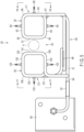
- the induction heating device 20 comprises a first coil C1 and a second coil C2.
- the first coil C1 contains a first coil portion 30 including a plurality (for example, six) of turn portions 31, 32, 33, 34, 35 and 36.
- the first coil portion 30 includes a first axis X1 (shown in FIGS. 3 and 4 ) passing through the centers of the turn portions 31, 32, 33, 34, 35 and 36.
- first axis X1 shown in FIGS. 3 and 4
- the turn portions 31 to 36 have shapes equivalent to each other (rounded regular squares).
- the second coil C2 contains a second coil portion 40 including a plurality (for example, six) of turn portions 41, 42, 43, 44, 45 and 46.
- the second coil portion 40 includes a second axis X2 (shown in FIGS. 3 and 4 ) passing through the centers of the turn portions 41, 42, 43, 44, 45 and 46.
- the turn portions 41 to 46 have shapes equivalent to each other (rounded regular squares).
- FIG. 6 is a side view of the first coil C1 as seen from the direction of an arrow F6 in FIG. 5 .
- FIG. 7 is a side view of the second coil C2 as seen from the direction of an arrow F7 in FIG. 5 .
- FIG. 8 is a perspective view of the induction heating device 20 assembled in the frame structure 50.
- the frame structure 50 is made, for example, of an electrically insulating material such as fiber-reinforced plastic (FRP) .
- FRP fiber-reinforced plastic
- the first coil C1 and the second coil C2 are each constituted by a conductor 51 made of a solid or hollow copper material whose cross section is circular.
- the first coil C1 and the second coil C2 are each formed by winding the conductor 51 in a left-handed (counterclockwise) direction, for example.
- the cross-section of the conductor 51 is constant in the length direction of the conductor 51.
- the cross-section of the conductor 51 may as well be other than circular (for example, quadrangular).
- the surface of the conductor 51 is covered by an insulating coating member 52 (a part of which is shown in FIGS. 5 and 8 ) made of an electrical insulating material such as glass fiber or the like.
- the first coil portion 30 and the second coil portion 40 are 180° rotationally symmetrical with each other about a virtual point Z1 when viewed from above. That is, the shape of the first coil portion 30 rotated by 180° around the virtual point Z1 is substantially equal to that of the second coil portion 40.
- the first coil portion 30 and the second coil portion 40 may as well have respective shapes which are line symmetrical with each other about the central axis of the workpiece (the stabilizer 4) as the axis of symmetry.
- the first coil portion 30 and the second coil portion 40 are arranged so that their respective axes X1 and X2 (shown in FIGS. 3 and 4 ) are parallel to each other.
- a workpiece placement section 55 is formed between the first coil portion 30 and the second coil portion 40.
- the stabilizer 4 as an example of a bar-shaped workpiece, is inserted.
- a part (a bush attachment portion) of the stabilizer 4 is placed in the work placement section 55 along the axes X1 and X2.
- the first coil portion 30, which is a main component of the first coil C1 includes a plurality (for example, six) of turn portions 31, 32, 33, 34, 35 and 36. These turn portions 31 to 36 have a common shape when the first coil portion 30 is viewed from the front side, as shown in FIG. 5 .
- Each of the turn portions 31-36 includes a first side portion 61 opposing the work placement section 55, a second side portion 62 opposing the work placement section 55, an upper third side portion 63, a lower fourth side portion 64, a first corner portion 65, a second corner portion 66, a third corner portion 67 and a fourth corner portion 68.
- the first side portion 61, the second side portion 62, the third side portion 63 and the fourth side portion 64 all have substantially straight or nearly straight shapes.
- the lengths of these side portions 61, 62, 63 and 64 are approximately the same as each other.
- the first coil portion 30 have a shape resembling a rounded regular rectangle when viewed from the front side as shown in FIG. 5 .
- the first coil portion 30 may as well be of a cylindrical shape.
- the first corner portion 65 is formed between the first side portion 61 and the third side portion 63.
- the second corner portion 66 is formed between the second side portion 62 and the third side portion 63.
- the third corner portion 67 is formed between the second side portion 62 and the fourth side portion 64.
- the fourth corner portion 68 is formed between the first side portion 61 and the fourth side portion 64.
- the corner portions 65 to 68 all have circular arc shapes.
- the corner portions 65 to 68 may have a shape other than a circular arc (for example, a shape including bending angles close to a right angle).
- the turn portions 31 to 36 of the first coil portion 30 are formed to have a predetermined pitch P1 to P5 (shown in FIG. 4 ) in the direction along the first axis X1. More specifically, a narrow pitch P1 is set by the first turn portion 31 and the second turn portion 32 in one axial end portion of the first coil portion 30. In the other axial end of the first coil portion 30, a narrow pitch P5 is set by the fifth turn portion 35 and the sixth turn portion 36.
- the pitch P1 and the pitch P5 are equivalent to each other.
- a medium pitch P3 is set by the third turn portion 33 and the fourth turn portion 34.
- the central pitch P3 is greater than or equal to the pitches P1 and P5 in the respective end portions. Note that, preferably, the pitch P3 in the center is greater than the pitches P1 and P5 of the respective end portions.
- a wide pitch P2 is set by the second turn portion 32 and the third turn portion 33. Further, by the fourth turn portion 34 and the fifth turn portion 35, a wide pitch P4 is set. The pitch P2 and the pitch P4 are equivalent to each other. Further, the pitches P2 and P4 are greater than the medium pitch P3.
- first narrow pitch portions 71 and 72 having the smallest pitches P1 and P5, respectively, are formed in the respective end portions of the first coil portion 30. Further, in the center of the first coil portion 30, a first medium pitch portion 75 having the medium pitch P3 is formed. A first wide pitch portion 73 having the pitch P2 is formed between one narrow pitch portion 71 and the medium pitch portion 75. A first wide pitch portion 74 having pitch P4 is formed between the other narrow pitch portion 72 and the medium pitch portion 75.
- the first side portions 61 of the respective turn portions 31 to 36 of the first coil portion 30 are substantially parallel to each other.
- the third side portions 63 of the respective turn portions 31 to 36 as well are substantially parallel to each other.
- the fourth side portions 64 of the respective turn portions 31 to 36 are also substantially parallel to each other.
- such an expression as "substantially parallel” covers a concept that includes parallelism in the strict sense of geometry, but also includes errors within a tolerable range, which may occur during the manufacturing process and assembly of the coils C1 and C2.
- the first side portion 61 extends in a direction approximately perpendicular to the first axis X1. Therefore, the pitch angle of the first side portion 61 is substantially zero. Further, as the first coil portion 30 is viewed from above as shown in FIG. 4 , the third side portion 63 and the fourth side portion 64 each extend in a direction substantially perpendicular to the first axis X1. Therefore, the pitch angles of the third side portion 63 and the fourth side portion 64 as well are substantially zero.
- the second side portion 62 which is located on a side opposite to the work placement section 55, has a shape in which a first pitch angle ⁇ 1 (shown in part in FIG. 6 ) varies according to the pitches P1 to P5 of the turn portions 31 to 36.
- the first pitch angle ⁇ 1 is given to the second side portion 62.
- the pitch angles of the sections which form the wide pitch portions 73 and 74 are greater than those of the portions forming the narrow pitch portions 71 and 72.
- a first positioning member 80 is attached to each of the turn portions 31 to 36 of the first coil portion 30 .
- the first positioning member 80 is formed, for example, by brazing a bolt to the conductor 51.
- a fixing means such as a nut
- One end 30a of the first coil portion 30 is connected to a first electrode member 82 (shown in FIG. 4 ) via a first feeder conductor 81.
- the other end 30b of the first coil portion 30 is connected to one end 40a of the second coil portion 40 via a connecting conductor 83.
- the other end 40b of the second coil portion 40 is connected to a second electrode member 85 (shown in FIGS. 4 and 5 ) via the second feeder conductor 84.
- the first electrode member 82 and the second electrode member 85 are connected to an AC power supply 86 for applying high frequency voltage to the first coil C1 and the second coil C2.
- the second coil C2 will now be described.
- the second coil portion 40 which is a main component of the second coil C2 includes a plurality (for example, six) of turn portions 41, 42, 43, 44, 45 and 46. These turn portions 41 to 46 have a common shape when the second coil portion 40 is viewed from the front side, as shown in FIG. 5 . As shown in FIG. 4 , the turn portions 41 to 46 of the second coil portion 40 oppose the turn portions 31 to 36 of the first coil portion 30, respectively.
- Each of the turn portions 41 to 46 includes a fifth side portion 101 opposing the work placement section 55, a sixth side portion 102 located on a side opposite to the work placement section 55, an upper seventh side portion 103, a lower eighth side portion 104, a fifth corner portion 105, a sixth corner portion 106, a seventh corner portion 107 and an eighth corner portion 108.
- the fifth side portion 101, the sixth side portion 102, the seventh side portion 103 and the eighth side portion 104 all have substantially straight or nearly straight shapes.
- the lengths of these side portions 101, 102, 103, and 104 are approximately the same as each other.
- the second coil portion 40 has a shape resembling a rounded square when viewed from the front side, as shown in FIG. 5 .
- the second coil portion 40 may as well be of a cylindrical shape.
- the fifth corner portion 105 is formed between the fifth side portion 101 and the seventh side portion 103.
- the sixth corner portion 106 is formed between the sixth side portion 102 and the seventh side portion 103.
- the seventh corner portion 107 is formed between the sixth side portion 102 and the eighth side portion 104.
- the eighth corner portion 108 is formed between the fifth side portion 101 and the eighth side portion 104.
- the corner portions 105 to 108 all have circular arc shapes. Note that the corner portions 105 to 108 may have a shape other than a circular arc (for example, a shape including bending angles close to a right angle).
- the turn portions 41 to 46 of the second coil portion 40 are formed to have predetermined pitches P6 to P10 (shown in FIG. 4 ) in the direction along the second axis X2. More specifically, a narrow pitch P6 is set by the first turn portion 41 and the second turn portion 42 in one axial end portion of the second coil portion 40. In the other axial end of the second coil portion 40, a narrow pitch P10 is set by the fifth turn portion 45 and the sixth turn portion 46. The pitch P6 and the pitch P10 are equivalent to each other.
- a medium pitch P8 is set by the third turn portions and the fourth turn portion4.
- the central pitch P8 is greater than the pitches P6 and P10 in the respective end portions.
- the central pitch P8 is greater than the pitches P6 and P10 of the respective end portions.
- the central pitch P8 should be greater than the pitches P6 and P10 at the respective end portions.
- a wide pitch P7 is set by the second turn portion 42 and the third turn portion 43.
- a larger pitch P9 is set by the fourth turn portion 44 and the fifth turn portion 45.
- the pitch P7 and the pitch P9 are equivalent to each other.
- the pitches P7 and P9 are wider than the medium pitch P8.
- second narrow pitch portions 111 and 112 having the smallest pitches P6 and P10 are formed in the respective end portions of the second coil portion 40.
- a second medium pitch portion 115 having the medium pitch P8 is formed in the center of the second coil portion 40.
- a second wide pitch portion 113 having the pitch P7 is formed between one narrow pitch portion 111 and the medium pitch portion 115.
- a second wide pitch portion 114 having the pitch P9 is formed between the other narrow pitch portion 112 and the medium pitch portion 115.
- the fifth side portions 101 of the respective turn portions 41 to 46 of the second coil portion 40 are substantially parallel to each other.
- the seventh side portions 103 of the respective turn portions 41 to 46 as well are substantially parallel to each other.
- the eighth side portions 104 of the respective turn portions 41 to 46 are also substantially parallel to each other.
- the fifth side portion 101 extends in a direction approximately perpendicular to the second axis X2. Therefore, the pitch angle of the fifth side portion 101 is substantially zero. Further, when the second coil portion 40 is viewed from above as shown in FIG. 4 , the seventh side portion 103 and the eighth side portion 104 each extend in a direction substantially perpendicular to the second axis X2. With this structure, the pitch angles of the seventh side portion 103 and the eighth side portion 104 are substantially zero.
- the sixth side portion 102 which is located on a side opposite to the work placement section 55, has a shape in which a second pitch angle ⁇ 2 (shown in part in FIG. 7 ) varies according to the pitches P6 to P10 of the turn portions 41 to 46.
- the second pitch angle ⁇ 2 is given to the sixth side portion 102.
- the pitch angles of the sections which form the wide pitch portions 113 and 114 are greater than the pitch angles of the sections forming the narrow pitch portions 111 and 112.
- a second positioning member 120 is attached to each of the turn portions 41 to 46 of the second coil portion 40.
- the second positioning member 120 is formed, for example, by brazing a bolt to the conductor 51.
- the end portion of the first coil C1 and the end portion of the second coil C2 may be electrically and mechanically connected to each other by a connecting portion 88.
- the first coil C1 and the second coil C2 can be formed separately and then connected to each other by brazing or the like at the connecting portion 88.
- FIGS. 3 and 8 show a conductor adjacent portion 90.
- the feeder conductor 81 and the connecting conductor 83 are arranged substantially parallel to each other.
- the feeder conductor 81 is electrically connected with the first coil portion 30.
- the connecting conductor 83 is electrically connected with the second coil portion 40.
- substantially parallel covers a concept that includes parallelism in the strict sense of geometry, but also includes variations in shape which may inevitably occur during the manufacturing process of the coil portions 30 and 40 and errors tolerable in terms of the specification of the product.
- currents indicated by arrows A1 and A2 in FIG.
- a solid line L1 shown in FIG. 9 indicates the relationship between the longitudinal location of the to-be-heated part and the heat generation density when the to-be-heated part of a bar-shaped workpiece was heated using the induction heating device 20 of this embodiment.
- the induction heating device 20 of this embodiment includes narrow pitch portions 71 and 72 formed on respective ends of the first coil portion 30, a medium pitch portion 75 formed in the center and wide pitch portions 73 and 74 formed on respective sides of the medium pitch portion 75.
- the induction heating device 20 further includes narrow pitch portions 111 and 112 formed on respective ends of the second coil portion 40, a medium pitch portion 115 formed in the center and wide pitch portions 113 and 114 formed on respective sides of the medium pitch portion 115.
- a dashed line L2 shown in FIG. 9 indicates the temperature distribution of the to-be-heated part when a bar-shaped workpiece was heated by a conventional induction heating device (having a constant coil pitch). When a coil having a constant pitch is used for heating, the entire width of the coil is substantially evenly heated.
- a solid line L3 shown in FIG. 10 indicates the temperature distribution at the moment when the heating by the induction heating device 20 of this embodiment was stopped. When the heating was stopped, some of the heat near both ends of the to-be-heated part escapes therefrom. Note here that, as shown in FIG. 9 , during the heating, the heat generation density near both ends of the coil width W1 was at maximum, and the temperature in the center was also high to some extent. With this configuration, as shown by the solid line L3 in FIG. 10 , the temperature of the to-be-heated part after the heating was stopped was equalized and the to-be-heated part was maintained in a predetermined temperature range T1.
- a dashed line L4 shown in FIG. 10 indicates the temperature distribution at the moment when the heating by the conventional coil was stopped. As indicated by the dashed line L4, the temperature near both ends of the to-be-heated part escapes to the surroundings and becomes considerably lower than that in the center of the to-be-heated part. Thus, it was difficult to maintain the entire to-be-heated part within the predetermined temperature range T1.
- FIG. 11 is a plan view of an induction heating device 20A according to the second embodiment.
- pitches P11 and P12 in one end portion are narrower than a pitch P13 in the center.
- Pitches P14 and P15 in the other end portion are narrower than the pitch P13 in the center. That is, first narrow pitch portions 71A and 72A are formed in respective end portions of the first coil portion 30A.
- a first wide pitch portion 73A is formed between the narrow pitch portions 71A and 72A.
- pitches P16 and P17 in one end portion are narrower than a pitch P18 in the center.
- pitches P19 and P20 in the other end portion are narrower than the pitch P18 in the center.
- second narrow pitches portions 111A and 112A are formed in respective end portions of the second coil portion 40A.
- a second wide pitch portion 113A is formed between the narrow pitch portions 111A and 112A.
- the induction heating device 20A of the second embodiment has a configuration and effect similar to those of the induction heating device 20 of the first embodiment ( FIGS. 3 to 8 ), common reference symbols to those of the first embodiment will be designated and the explanations thereof will be omitted.
- FIG. 12 shows the relationship between the longitudinal location and the heat generation density in the to-be-heated part subjected to heating by the induction heating device 20A. As shown in FIG. 12 , when heated by the induction heating device 20A, the heat generation density in both ends of the coil width W2 (shown in FIGS. 11 and 12 ) is greater than the heat generation density in the center.
- FIG. 13 shows the temperature distribution of the to-be-heated part when tens of seconds elapsed after the heating by the induction heating device 20A was stopped.
- the heating is stopped, some of the heat near both ends of the to-be-heated part escapes from the to-be-heated part.
- the heat generation density near both ends of the coil width W2 is high during the heating. Therefore, as shown in FIG. 13 , the temperature of the to-be-heated part after heating was stopped was maintained within a predetermined temperature range T2.
- the number of turn portions of the first coil portion and the second coil portion may be other than six. Further, if necessary, there may be a plurality of medium pitch portions provided.
- the bar-shaped workpiece is not limited to stabilizers for vehicles, and in short, the induction heating device of the present invention can be applied to any bar-shaped workpiece that needs to be heated in part of its length direction.
Landscapes
- Physics & Mathematics (AREA)
- Electromagnetism (AREA)
- Chemical & Material Sciences (AREA)
- Engineering & Computer Science (AREA)
- Thermal Sciences (AREA)
- Crystallography & Structural Chemistry (AREA)
- Mechanical Engineering (AREA)
- Materials Engineering (AREA)
- Metallurgy (AREA)
- Organic Chemistry (AREA)
- Power Engineering (AREA)
- General Induction Heating (AREA)
Abstract
Description
- The present invention relates generally to an induction heating device which heats bar-shaped workpieces such as metal rods and steel pipes by means of a high-frequency induction coil, and to a method for heating stabilizers.
- Stabilizer devices to be installed in the suspension mechanism of a vehicle includes a stabilizer made from a steel-made rod or a hollow material and a support for supporting the stabilizer to the vehicle body. The stabilizer includes a torsion unit which extends in a width direction of the vehicle and a pair of arm units connected to respective ends of the torsion unit via bend portions. An example of the support unit is a pair of bush units with a rubber bush. Via the bush units, the stabilizer is supported onto the vehicle body. Distal end portions of the arms are connected to a suspension member or the like via a connecting member.
- In order to fix the rubber bush to the stabilizer, for example, a thermosetting adhesive may be used. In such cases, a longitudinal part of the stabilizer(, which is a bush attachment portion) is heated. The rubber bush to which the adhesive is applied is placed over the heated stabilizer. Then, the adhesive cures while the rubber bush is being pressurized.
- In order to heat a longitudinal part of a bar-shaped workpiece, a high-frequency induction heating device may be used. For example, the high-frequency induction heating device discussed in Patent Literature 1 has a pair of induction heating coils. Generally, induction heating coils are constituted by conductors wound at the same pitch.
- Patent Literature 1:
JP 6832312 B - It has been found that the following problems occur when a longitudinal part of a bar-shaped workpiece is heated evenly by a conventional induction heating coil.
- That is, when the to-be-heated part of a bar-shaped workpiece is heated by a conventional induction heating coil (a coil with a constant pitch), the to-be-heated part is heated with an approximately uniform heat generation density within the width of the coil. However, from immediately after the start of heating, part of the heat escapes to the surroundings of the to-be-heated part due to the heat transfer effect. As a result, the temperatures near both ends of the to-be-heated part to becomes lower than that near the central portion of the to-be-heated part.
- To attach a rubber bush to the heated stabilizer, the stabilizer needs to be transported to the rubber bush attachment stage. Here, it is inevitable that the temperature of the bush attachment area (the to-be-heated part) drops during the transfer. In particular, the temperature near both ends of the bush attachment part drops. Therefore, it is necessary to control the temperature during heating so that the temperature of the bush attachment part is maintained at the curing temperature of the adhesive.
- Stabilizers are subjected to shot peening to impart compressive residual stress thereto to increase their durability. When stabilizers are heated to the permissive temperature or the higher, the above-described compressive residual stress will dissipate. Therefore, it is necessary to control the temperature so that the temperature of the to-be-heated part does not exceed the permissive value. Further, when adhering the rubber bush, the to-be-heated part need to be kept at a temperature at which the adhesive cures. Under these circumstances, it is conventionally difficult to carry out temperature control, and there has been room for improvement.
- An object of this invention is to provide an induction heating device which can heat the to-be-heated part of a bar-shaped workpiece, such as a stabilizer, to a nearly uniform temperature.
- One of embodiments is an induction heating device for heating a to-be-heated part of a bar-shaped workpiece such as a stabilizer, which includes a first coil and a second coil. The first coil includes a first coil portion comprising a plurality of turn portions and a first axis passing through the center of the first coil portion. The second coil includes a second coil portion comprising a plurality of turn portions and a second axis passing through the center of the second coil portion. The first coil portion and the second coil portion may each have an even number of turns or an odd number of turns. Between the first coil portion and the second coil portion, a workpiece placement section is formed.
- The first coil includes a pair of first narrow pitch portions formed in respective end portions of the first coil portion and a first wide pitch portion formed between the pair of first narrow pitch portions and having a pitch is wider than that of the first narrow pitch portion. Further, the second coil includes a pair of second narrow pitch portions formed in respective end portions of the second coil portion and a second wide pitch portion formed between the pair of second narrow pitch portions and having a pitch wider than that of the second narrow pitch portion.
- The induction heating device of this embodiment may include a first medium pitch portion formed in the center of the first coil portion and a second medium pitch portion formed in the center of the second coil portion. The pitch of the first medium pitch portion is wider than that of the first narrow pitch portion and narrower than that of the first wide pitch portion. The pitch of the second medium pitch portion is wider than that of the second narrow pitch portion and narrower than that of the second wide pitch portion.
- Each of the turn portions of the first coil portion may include a first side portion opposing the workpiece placement section, a second side portion on a side opposite to the workpiece placement section, an upper third side portion, and a lower fourth side portion. As viewing the first coil portion from a direction of a side, the first side portions may be parallel to each other and the first side portions may each extend in a direction perpendicular to the first axis. The first coil portion may be inclined with respect to the workpiece placement section. Each of the turn portions of the second coil portion may include a fifth side portion opposing the workpiece placement section, a sixth side portion opposing the workpiece placement section, an upper seventh side portion and a lower eighth side portion. As viewing the second coil portion from a direction from a side, the fifth side portions may be parallel to each other and the fifth side portions may each extend in a direction perpendicular to the second axis. The second coil portion may be inclined with respect to the workpiece placement section.
- In one example of the first coil portion, the third side portions may be parallel to each other and the third side portions each may extend in a direction perpendicular to the first axis as the first coil portion is viewed from above. The fourth side portions may be parallel to each other and the fourth side portions may each extend in a direction perpendicular to the first axis. When the first coil portion is viewed from a direction of a side, the second side portion has a first pitch angle in accordance with the first narrow pitch portion and the first wide pitch portion. Note that the third side portion or the fourth side portion may have the first pitch angle. In one example of the second coil portion, the seventh side portions may be parallel to each other and the seventh side portions may each extend in a direction perpendicular to the second axis when the second coil portion is viewed from above. Further, the eighth side portions may be parallel to each other and the eighth side portions may each extend in a direction perpendicular to the second axis. When the second coil portion is viewed from a direction of a side, the sixth side portion has a second pitch angle in accordance with the second narrow pitch portion and the second wide pitch portion. Note that the seventh side portion or the eighth side portion may have the second pitch angle.
- One embodiment of an induction heating device may include a frame structure made of an electrically insulating material, a first positioning member provided on each of the turn portions of the first coil portion and a second positioning member provided on each of the turn portions of the second coil portion. The first positioning member and the second positioning member are fixed to the frame structure.
- The induction heating device may include a feeder conductor that is electrically connected with the first coil portion, a connecting conductor that electrically connects the first coil portion and the second coil portion to each other, and a conductor adjacent portion in which the feeder conductor and the connecting conductor are adjacent to each other and extend in the same direction. In the conductor adjacent portion, the feeder conductor and the connecting conductor are arranged so that the direction of the current flowing through the feeder conductor and the direction of the current flowing through the connecting conductor are opposite to each other.
- According to the induction heating device of this embodiment, it is possible to heat a longitudinal part of a bar-shaped workpiece, such as a stabilizer for a vehicle, for example, to a nearly uniform temperature range.
-
-
FIG. 1 is a perspective view schematically showing a part of a vehicle and a stabilizer. -
FIG. 2 is a perspective view showing a part of the stabilizer shown inFIG. 1 and a rubber bush. -
FIG. 3 is a perspective view showing a part of the induction heating device according to the first embodiment. -
FIG. 4 is a plan view of the induction heating device shown inFIG. 3 . -
FIG. 5 is a front view of the induction heating device shown inFIG. 3 . -
FIG. 6 is a side view of a first coil taken along line F6-F6 inFIG. 5 . -
FIG. 7 is a side view of a second coil taken along line F7-F7 inFIG. 5 . -
FIG. 8 is a perspective view showing the induction heating device shown inFIG. 3 when assembled to a frame structure. -
FIG. 9 is a diagram showing a relationship between a location of a to-be-heated part heated by the induction heating device and a heat generation density. -
FIG. 10 is a diagram showing the relationship between the location and temperature of the to-be-heated part after stopping of heating by the induction heating device. -
FIG. 11 is a plan view of a part of an induction heating device according to the second embodiment. -
FIG. 12 is a diagram showing the relationship between the location of the to-be-heated part heated by the induction heating device shown inFIG. 11 and the heat generation density. -
FIG. 13 is a diagram showing the relationship between the location and temperature of the to-be-heated part after stopping the heating by the induction heating device shown inFIG. 11 . - An induction heating device of the first embodiment will be described below with reference to
FIGS. 1 to 10 . -
FIG. 1 shows a part of avehicle 2 equipped with a stabilizer device 1. The stabilizer device 1 comprises a solid orhollow stabilizer 4 made of steel and asupport unit 5 that supports thestabilizer 4 to a vehicle body 3. Thestabilizer 4 extends in the width direction (the direction indicated by an arrow Y) of the vehicle body 3. One example of thesupport unit 5 comprises a pair ofrubber bushes stabilizer 4 is an example of a bar-shaped workpiece. - The
stabilizer 4 includes atorsion unit 10 extending in the width direction of the vehicle body 3 and a pair ofarm units torsion unit 10 is supported on a part of the vehicle body 3, for example, via therubber bushes arm units members stabilizer 4 are subjected to shot peening to impart a compressive residual stress thereto. A resin-based coating film is applied on the surface ofstabilizer 4. - The pair of
rubber bushes rubber bush 6 is shown as a representative example inFIG. 2 . Therubber bush 6 is adhered to a longitudinal part (a bush attachment portion) of thestabilizer 4 by means of athermosetting adhesive 15. One example of therubber bush 6 shown inFIG. 2 is constituted by a pair of two divided parts, namely, afirst bush piece 6a and asecond bush piece 6b. - When attaching the
rubber bush 6 onto thestabilizer 4, the bush attachment portion of thestabilizer 4 is heated by an induction heating device 20 (shown inFIGS. 3 to 8 ). The inner surfaces of thefirst bush piece 6a and thesecond bush piece 6b are coated with a thermosetting adhesive in advance. Thefirst bush piece 6a and thesecond bush piece 6b are overlaid on the bush attachment portion heated to a predetermined temperature, and the adhesive 15 cures while being pressurized. -
FIGS. 3 to 8 show theinduction heating device 20 according to the first embodiment.FIG. 3 is a perspective view showing a part of theinduction heating device 20,FIG. 4 is a plan view of theinduction heating device 20, andFIG. 5 is a front view of theinduction heating device 20. - The
induction heating device 20 comprises a first coil C1 and a second coil C2. The first coil C1 contains afirst coil portion 30 including a plurality (for example, six) ofturn portions first coil portion 30 includes a first axis X1 (shown inFIGS. 3 and4 ) passing through the centers of theturn portions first coil portion 30 is viewed from the front side as shown inFIG. 5 , theturn portions 31 to 36 have shapes equivalent to each other (rounded regular squares). - The second coil C2 contains a
second coil portion 40 including a plurality (for example, six) ofturn portions second coil portion 40 includes a second axis X2 (shown inFIGS. 3 and4 ) passing through the centers of theturn portions second coil portion 40 is viewed from the front side as shown inFIG. 5 , theturn portions 41 to 46 have shapes equivalent to each other (rounded regular squares). -
FIG. 6 is a side view of the first coil C1 as seen from the direction of an arrow F6 inFIG. 5 .FIG. 7 is a side view of the second coil C2 as seen from the direction of an arrow F7 inFIG. 5 .FIG. 8 is a perspective view of theinduction heating device 20 assembled in theframe structure 50. Theframe structure 50 is made, for example, of an electrically insulating material such as fiber-reinforced plastic (FRP) . - The first coil C1 and the second coil C2 are each constituted by a
conductor 51 made of a solid or hollow copper material whose cross section is circular. The first coil C1 and the second coil C2 are each formed by winding theconductor 51 in a left-handed (counterclockwise) direction, for example. The cross-section of theconductor 51 is constant in the length direction of theconductor 51. The cross-section of theconductor 51 may as well be other than circular (for example, quadrangular). The surface of theconductor 51 is covered by an insulating coating member 52 (a part of which is shown inFIGS. 5 and8 ) made of an electrical insulating material such as glass fiber or the like. - As shown in
FIG. 4 , thefirst coil portion 30 and thesecond coil portion 40 are 180° rotationally symmetrical with each other about a virtual point Z1 when viewed from above. That is, the shape of thefirst coil portion 30 rotated by 180° around the virtual point Z1 is substantially equal to that of thesecond coil portion 40. Note that thefirst coil portion 30 and thesecond coil portion 40 may as well have respective shapes which are line symmetrical with each other about the central axis of the workpiece (the stabilizer 4) as the axis of symmetry. Thefirst coil portion 30 and thesecond coil portion 40 are arranged so that their respective axes X1 and X2 (shown inFIGS. 3 and4 ) are parallel to each other. Between thefirst coil portion 30 and thesecond coil portion 40, aworkpiece placement section 55 is formed. In theworkpiece placement section 55, thestabilizer 4, as an example of a bar-shaped workpiece, is inserted. A part (a bush attachment portion) of thestabilizer 4 is placed in thework placement section 55 along the axes X1 and X2. - An example of the specific structure the first coil C1 will now be described with reference to
FIGS. 3 to 6 . - As shown in
FIGS. 3 and4 , thefirst coil portion 30, which is a main component of the first coil C1, includes a plurality (for example, six) ofturn portions portions 31 to 36 have a common shape when thefirst coil portion 30 is viewed from the front side, as shown inFIG. 5 . - Each of the turn portions 31-36 includes a
first side portion 61 opposing thework placement section 55, asecond side portion 62 opposing thework placement section 55, an upperthird side portion 63, a lowerfourth side portion 64, afirst corner portion 65, asecond corner portion 66, athird corner portion 67 and afourth corner portion 68. - The
first side portion 61, thesecond side portion 62, thethird side portion 63 and thefourth side portion 64 all have substantially straight or nearly straight shapes. The lengths of theseside portions first coil portion 30 have a shape resembling a rounded regular rectangle when viewed from the front side as shown inFIG. 5 . Note here that thefirst coil portion 30 may as well be of a cylindrical shape. - The
first corner portion 65 is formed between thefirst side portion 61 and thethird side portion 63. Thesecond corner portion 66 is formed between thesecond side portion 62 and thethird side portion 63. Thethird corner portion 67 is formed between thesecond side portion 62 and thefourth side portion 64. Thefourth corner portion 68 is formed between thefirst side portion 61 and thefourth side portion 64. Thecorner portions 65 to 68 all have circular arc shapes. Thecorner portions 65 to 68 may have a shape other than a circular arc (for example, a shape including bending angles close to a right angle). - The
turn portions 31 to 36 of thefirst coil portion 30 are formed to have a predetermined pitch P1 to P5 (shown inFIG. 4 ) in the direction along the first axis X1. More specifically, a narrow pitch P1 is set by thefirst turn portion 31 and thesecond turn portion 32 in one axial end portion of thefirst coil portion 30. In the other axial end of thefirst coil portion 30, a narrow pitch P5 is set by thefifth turn portion 35 and thesixth turn portion 36. The pitch P1 and the pitch P5 are equivalent to each other. - In the axial center of the
first coil portion 30, a medium pitch P3 is set by thethird turn portion 33 and thefourth turn portion 34. The central pitch P3 is greater than or equal to the pitches P1 and P5 in the respective end portions. Note that, preferably, the pitch P3 in the center is greater than the pitches P1 and P5 of the respective end portions. - A wide pitch P2 is set by the
second turn portion 32 and thethird turn portion 33. Further, by thefourth turn portion 34 and thefifth turn portion 35, a wide pitch P4 is set. The pitch P2 and the pitch P4 are equivalent to each other. Further, the pitches P2 and P4 are greater than the medium pitch P3. - In the above-described manner, first
narrow pitch portions first coil portion 30. Further, in the center of thefirst coil portion 30, a firstmedium pitch portion 75 having the medium pitch P3 is formed. A firstwide pitch portion 73 having the pitch P2 is formed between onenarrow pitch portion 71 and themedium pitch portion 75. A firstwide pitch portion 74 having pitch P4 is formed between the othernarrow pitch portion 72 and themedium pitch portion 75. - As shown in
FIGS. 3 and4 , thefirst side portions 61 of therespective turn portions 31 to 36 of thefirst coil portion 30 are substantially parallel to each other. Thethird side portions 63 of therespective turn portions 31 to 36 as well are substantially parallel to each other. Thefourth side portions 64 of therespective turn portions 31 to 36 are also substantially parallel to each other. In this specification, such an expression as "substantially parallel" covers a concept that includes parallelism in the strict sense of geometry, but also includes errors within a tolerable range, which may occur during the manufacturing process and assembly of the coils C1 and C2. - As the
first coil portion 30 is viewed from a direction of a side surface, thefirst side portion 61 extends in a direction approximately perpendicular to the first axis X1. Therefore, the pitch angle of thefirst side portion 61 is substantially zero. Further, as thefirst coil portion 30 is viewed from above as shown inFIG. 4 , thethird side portion 63 and thefourth side portion 64 each extend in a direction substantially perpendicular to the first axis X1. Therefore, the pitch angles of thethird side portion 63 and thefourth side portion 64 as well are substantially zero. - On the other hand, the
second side portion 62, which is located on a side opposite to thework placement section 55, has a shape in which a first pitch angle θ1 (shown in part inFIG. 6 ) varies according to the pitches P1 to P5 of theturn portions 31 to 36. In other words, the first pitch angle θ1 is given to thesecond side portion 62. Moreover, the pitch angles of the sections which form thewide pitch portions narrow pitch portions - To each of the
turn portions 31 to 36 of thefirst coil portion 30, afirst positioning member 80 is attached. Thefirst positioning member 80 is formed, for example, by brazing a bolt to theconductor 51. By inserting thefirst positioning member 80 into a hole formed in the frame structure 50 (shown inFIG. 8 ) and fixing it to theframe structure 50 by means of a fixing means such as a nut, the pitches P1 to P5 of thefirst coil portion 30 can be accurately maintained. - One
end 30a of thefirst coil portion 30 is connected to a first electrode member 82 (shown inFIG. 4 ) via afirst feeder conductor 81. Theother end 30b of thefirst coil portion 30 is connected to oneend 40a of thesecond coil portion 40 via a connectingconductor 83. Theother end 40b of thesecond coil portion 40 is connected to a second electrode member 85 (shown inFIGS. 4 and5 ) via thesecond feeder conductor 84. Thefirst electrode member 82 and thesecond electrode member 85 are connected to anAC power supply 86 for applying high frequency voltage to the first coil C1 and the second coil C2. - The second coil C2 will now be described.
- As shown in
FIGS. 3 and4 , thesecond coil portion 40, which is a main component of the second coil C2, includes a plurality (for example, six) ofturn portions portions 41 to 46 have a common shape when thesecond coil portion 40 is viewed from the front side, as shown inFIG. 5 . As shown inFIG. 4 , theturn portions 41 to 46 of thesecond coil portion 40 oppose theturn portions 31 to 36 of thefirst coil portion 30, respectively. - Each of the
turn portions 41 to 46 includes afifth side portion 101 opposing thework placement section 55, asixth side portion 102 located on a side opposite to thework placement section 55, an upperseventh side portion 103, a lowereighth side portion 104, afifth corner portion 105, asixth corner portion 106, aseventh corner portion 107 and aneighth corner portion 108. - The
fifth side portion 101, thesixth side portion 102, theseventh side portion 103 and theeighth side portion 104 all have substantially straight or nearly straight shapes. The lengths of theseside portions second coil portion 40 has a shape resembling a rounded square when viewed from the front side, as shown inFIG. 5 . Note that thesecond coil portion 40 may as well be of a cylindrical shape. - The
fifth corner portion 105 is formed between thefifth side portion 101 and theseventh side portion 103. Thesixth corner portion 106 is formed between thesixth side portion 102 and theseventh side portion 103. Theseventh corner portion 107 is formed between thesixth side portion 102 and theeighth side portion 104. Theeighth corner portion 108 is formed between thefifth side portion 101 and theeighth side portion 104. Thecorner portions 105 to 108 all have circular arc shapes. Note that thecorner portions 105 to 108 may have a shape other than a circular arc (for example, a shape including bending angles close to a right angle). - The
turn portions 41 to 46 of thesecond coil portion 40 are formed to have predetermined pitches P6 to P10 (shown inFIG. 4 ) in the direction along the second axis X2. More specifically, a narrow pitch P6 is set by thefirst turn portion 41 and thesecond turn portion 42 in one axial end portion of thesecond coil portion 40. In the other axial end of thesecond coil portion 40, a narrow pitch P10 is set by thefifth turn portion 45 and thesixth turn portion 46. The pitch P6 and the pitch P10 are equivalent to each other. - Further, in the axial center of the
second coil portion 40, a medium pitch P8 is set by the third turn portions and the fourth turn portion4. The central pitch P8 is greater than the pitches P6 and P10 in the respective end portions. The central pitch P8 is greater than the pitches P6 and P10 of the respective end portions. Preferably, the central pitch P8 should be greater than the pitches P6 and P10 at the respective end portions. - A wide pitch P7 is set by the
second turn portion 42 and thethird turn portion 43. A larger pitch P9 is set by thefourth turn portion 44 and thefifth turn portion 45. The pitch P7 and the pitch P9 are equivalent to each other. Moreover, the pitches P7 and P9 are wider than the medium pitch P8. - In the manner described above, second
narrow pitch portions second coil portion 40. A secondmedium pitch portion 115 having the medium pitch P8 is formed in the center of thesecond coil portion 40. Between onenarrow pitch portion 111 and themedium pitch portion 115, a secondwide pitch portion 113 having the pitch P7 is formed. A secondwide pitch portion 114 having the pitch P9 is formed between the othernarrow pitch portion 112 and themedium pitch portion 115. - As shown in
FIGS. 3 and4 , thefifth side portions 101 of therespective turn portions 41 to 46 of thesecond coil portion 40 are substantially parallel to each other. Theseventh side portions 103 of therespective turn portions 41 to 46 as well are substantially parallel to each other. Theeighth side portions 104 of therespective turn portions 41 to 46 are also substantially parallel to each other. - When the
second coil portion 40 is viewed from the direction of the side surface, thefifth side portion 101 extends in a direction approximately perpendicular to the second axis X2. Therefore, the pitch angle of thefifth side portion 101 is substantially zero. Further, when thesecond coil portion 40 is viewed from above as shown inFIG. 4 , theseventh side portion 103 and theeighth side portion 104 each extend in a direction substantially perpendicular to the second axis X2. With this structure, the pitch angles of theseventh side portion 103 and theeighth side portion 104 are substantially zero. - On the other hand, the
sixth side portion 102, which is located on a side opposite to thework placement section 55, has a shape in which a second pitch angle θ2 (shown in part inFIG. 7 ) varies according to the pitches P6 to P10 of theturn portions 41 to 46. In other words, the second pitch angle θ2 is given to thesixth side portion 102. Moreover, the pitch angles of the sections which form thewide pitch portions narrow pitch portions - A
second positioning member 120 is attached to each of theturn portions 41 to 46 of thesecond coil portion 40. Thesecond positioning member 120 is formed, for example, by brazing a bolt to theconductor 51. By inserting thesecond positioning member 120 into a hole formed in the frame structure 50 (shown inFIG. 8 ) and fixing it to theframe structure 50 by means of a fixing means such as a nut, the pitches P6 to P10 of thesecond coil portion 40 can be accurately maintained. - As shown in
FIG. 5 , the end portion of the first coil C1 and the end portion of the second coil C2 may be electrically and mechanically connected to each other by a connectingportion 88. In this manner, the first coil C1 and the second coil C2 can be formed separately and then connected to each other by brazing or the like at the connectingportion 88. -
FIGS. 3 and8 show a conductoradjacent portion 90. In the conductoradjacent portion 90, thefeeder conductor 81 and the connectingconductor 83 are arranged substantially parallel to each other. Thefeeder conductor 81 is electrically connected with thefirst coil portion 30. The connectingconductor 83 is electrically connected with thesecond coil portion 40. In this specification, such an expression as "substantially parallel" covers a concept that includes parallelism in the strict sense of geometry, but also includes variations in shape which may inevitably occur during the manufacturing process of thecoil portions adjacent portion 90, currents (indicated by arrows A1 and A2 inFIG. 3 ) flow the feedingconductor 81 and the connectingconductor 83 in opposite directions therebetween. With this configuration, the magnetic flux generated in thefeeder conductor 81 and the magnetic flux generated in the connectingconductor 83 cancel each other. Thus, it is possible to avoid the magnetic fluxes generated in thefeeder conductor 81 and the connectingconductor 83 from adversely affecting the magnetic fields of thecoil portions - A solid line L1 shown in
FIG. 9 indicates the relationship between the longitudinal location of the to-be-heated part and the heat generation density when the to-be-heated part of a bar-shaped workpiece was heated using theinduction heating device 20 of this embodiment. Theinduction heating device 20 of this embodiment includesnarrow pitch portions first coil portion 30, amedium pitch portion 75 formed in the center andwide pitch portions medium pitch portion 75. Theinduction heating device 20 further includesnarrow pitch portions second coil portion 40, amedium pitch portion 115 formed in the center andwide pitch portions medium pitch portion 115. With this structure, the heat generation density by thecoil portions FIGS. 4 and9 ), and the heat generation density in the center of the coil width W1 was the second highest. - A dashed line L2 shown in
FIG. 9 indicates the temperature distribution of the to-be-heated part when a bar-shaped workpiece was heated by a conventional induction heating device (having a constant coil pitch). When a coil having a constant pitch is used for heating, the entire width of the coil is substantially evenly heated. - A solid line L3 shown in
FIG. 10 indicates the temperature distribution at the moment when the heating by theinduction heating device 20 of this embodiment was stopped. When the heating was stopped, some of the heat near both ends of the to-be-heated part escapes therefrom. Note here that, as shown inFIG. 9 , during the heating, the heat generation density near both ends of the coil width W1 was at maximum, and the temperature in the center was also high to some extent. With this configuration, as shown by the solid line L3 inFIG. 10 , the temperature of the to-be-heated part after the heating was stopped was equalized and the to-be-heated part was maintained in a predetermined temperature range T1. - A dashed line L4 shown in
FIG. 10 indicates the temperature distribution at the moment when the heating by the conventional coil was stopped. As indicated by the dashed line L4, the temperature near both ends of the to-be-heated part escapes to the surroundings and becomes considerably lower than that in the center of the to-be-heated part. Thus, it was difficult to maintain the entire to-be-heated part within the predetermined temperature range T1. -
FIG. 11 is a plan view of aninduction heating device 20A according to the second embodiment. In afirst coil portion 30A of thisinduction heating device 20A, pitches P11 and P12 in one end portion are narrower than a pitch P13 in the center. Pitches P14 and P15 in the other end portion are narrower than the pitch P13 in the center. That is, firstnarrow pitch portions first coil portion 30A. A firstwide pitch portion 73A is formed between thenarrow pitch portions - Similarly, in a
second coil portion 40A, pitches P16 and P17 in one end portion are narrower than a pitch P18 in the center. Further, pitches P19 and P20 in the other end portion are narrower than the pitch P18 in the center. That is, secondnarrow pitches portions second coil portion 40A. A secondwide pitch portion 113A is formed between thenarrow pitch portions induction heating device 20A of the second embodiment has a configuration and effect similar to those of theinduction heating device 20 of the first embodiment (FIGS. 3 to 8 ), common reference symbols to those of the first embodiment will be designated and the explanations thereof will be omitted. -
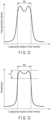
FIG. 12 shows the relationship between the longitudinal location and the heat generation density in the to-be-heated part subjected to heating by theinduction heating device 20A. As shown inFIG. 12 , when heated by theinduction heating device 20A, the heat generation density in both ends of the coil width W2 (shown inFIGS. 11 and12 ) is greater than the heat generation density in the center. -
FIG. 13 shows the temperature distribution of the to-be-heated part when tens of seconds elapsed after the heating by theinduction heating device 20A was stopped. When the heating is stopped, some of the heat near both ends of the to-be-heated part escapes from the to-be-heated part. Note here that, as shown inFIG. 12 , the heat generation density near both ends of the coil width W2 is high during the heating. Therefore, as shown inFIG. 13 , the temperature of the to-be-heated part after heating was stopped was maintained within a predetermined temperature range T2. - In implementing the present invention, the number of turn portions of the first coil portion and the second coil portion may be other than six. Further, if necessary, there may be a plurality of medium pitch portions provided. The bar-shaped workpiece is not limited to stabilizers for vehicles, and in short, the induction heating device of the present invention can be applied to any bar-shaped workpiece that needs to be heated in part of its length direction.
- 4 ... Stabilizer (bar-shaped workpiece), 20, 20A ... Induction heating device, C1 ... First coil, C2 ... Second coil, 30, 30A ... First coil portion, X1 ... First axis, 31 to 36 ... turn portion, 40, 40A ... Second coil portion, X2 ... Second axis, 41 to 46 ... turn portion, 50 ...
Frame structure 51 ... Conductor, 55 ... Work placement section, 61 ... First side portion, 62 ... Second side portion, 63 ... Third side portion, 64 ... Fourth side portion, 71, 71A, 72, 72A ... Narrow pitch portion, 73, 73A, 74 ... Wide pitch portion, 75 ... Medium pitch portion, 80 ... First positioning member, 81 ... Feeder conductor, 82 ... First electrode member, 83 ... Connecting conductor, 84 ... Feeder conductor, 85 ... Second electrode member, 90 ... Conductor adjacent portion, 101 ... Fifth side portion, 102 ... Sixth side portion, 103 ... Seventh side portion, 104 ... Eighth side portion, 111, 111A, 112, 112A ... Small pitch portion, 113, 113A, 114 ... Wide pitch portion, 115 ... Medium pitch portion, 120 ... Second positioning member.
Claims (7)
- An induction heating device for heating a to-be-heated part of a bar-shaped workpiece, comprising:a first coil (C1) including a first coil portion (30)(30A) comprising a plurality of turn portions and having a first axis (X1) passing through a center of the first coil portion (30)(30A);a second coil (C2) disposed to oppose the first coil (C1), including a second coil portion (40)(40A) comprising a plurality of turn portions, and having a second axis (X2) passing through a center of the second coil portion (40)(40A);a workpiece placement section (55) formed between the first coil portion (30)(30A) and the second coil portion (40)(40A), into which a bar-shaped workpiece is inserted;a pair of first narrow pitch portions (71,72)(71A,72A) formed in respective end portions of the first coil portion (30)(30A);at least one first wide pitch portion (73,74) (73A) formed between the pair of first narrow pitch portions (71,72) (71A,72A) and having a pitch greater than that of the first narrow pitch portions (71,72) (71A,72A);a pair of second narrow pitch portions (111,112) (111A,112A) formed in respective end portions of the second coil portion (40)(40A); andat least one second wide pitch portion (113,114)(113A) formed between the pair of second narrow pitch portions (111,112)(111A,112A) and having a pitch wider than that of the second narrow pitch portions (111,112)(111A,112A).
- The induction heating device according to claim 1, comprising:a first medium pitch portion (75) formed in a center of the first coil portion (30)(30A) and having a pitch wider than that of the first narrow pitch portion (71,72)(71A,72A) and narrower than that of the first wide pitch portion (73,74)(73A); anda second medium pitch portion (115) formed in a center of the second coil portion (40)(40A) and having a pitch wider than that of the second narrow pitch portions (111,112)(111A,112A) and narrower than that of the second wide pitch portions (113,114)(113A).
- The induction heating device according to claim 1, whereineach of the turn portions of the first coil portion (30)(30A) includes a first side portion (61) opposing the workpiece placement section (55), a second side portion (62) on a side opposite to the workpiece placement section (55), an upper third side (63), and a lower fourth side portion (64),the first side portions (61) are parallel to each other and the first side portions (61) extend in a direction perpendicular to the first axis (X1) as the first coil portion (30)(30A) is viewed from a side,each of the turn portions of the second coil portion (40)(40A) includes a fifth side portion (101) opposing the workpiece placement section (55), a sixth side (102) on a side opposite to the workpiece placement section (55), an upper seventh side (103), and a lower eighth side (104), andthe fifth side portions (101) are parallel to each other and the fifth side portions (101) extend in a direction perpendicular to the second axis (X2) as the second coil portion (40)(40A) is viewed from a side.
- The induction heating device according to claim 3, whereinthe third side portions (63) are parallel to each other and the third side portions (63) extend in a direction perpendicular to the first axis (X1), and the fourth side portions (64) are parallel to each other and the fourth side portions (64) extend in a direction perpendicular to the first axis (X1), as the first coil portion (30)(30A) is viewed from above,the second side portion (62) has a first pitch angle (θ1) according to the first narrow pitch portions (71,72)(71A,72A) and the first wide pitch portions (73,74)(73A) as the first coil portion (30)(30A) is viewed from the side,the seventh side portions (103) are parallel to each other and the seventh side portions (103) extend perpendicular to the second axis (X2) and the eighth side portions (104) are parallel to each other and the eighth side portions (104) extend perpendicular to the second axis (X2), as the second coil portion (40)(40A) is viewed from above, andthe sixth side portion (102) has a second pitch angle (θ2) according to the second narrow pitch portions (111,112) and the second wide pitch portions (113,114)(113A), as the second coil portion (40)(40A) is viewed from the side.
- The induction heating device according to claim 1, comprising:a frame structure (50) made of an electrically insulating material;a first positioning member (80) provided on each of the turn portions of the first coil portion (30)(30A) and fixed to the frame structure (50); anda second positioning member (120) provided on each of the turn portions of the second coil portion (40)(40A) and fixed to the frame structure (50).
- The induction heating device according to claim 1, comprising:a feeder conductor (81) electrically connected with the first coil portion (30)(30A);a connecting conductor (83) electrically connecting the first coil portion (30)(30A) and the second coil portion (40)(40A) to each other; anda conductor adjacent portion (90) in which the feeder conductor (81) and the connecting conductor (83) are arranged adjacent to each other and extend in a same direction and a direction of current flowing through the feeder conductor (81) and a direction of current flowing through the connecting conductor (83) are opposite to each other.
- A heating method for inductively heating a to-be-heated part of a stabilizer by placing the to-be-heated part between a first coil (C1) and a second coil (C2) and applying a high frequency voltage to the first coil (C1) and the second coil (C2),the first coil (C1) including a pair of first narrow pitch portions (71,72)(71A,72A) and a first wide pitch portion (73,74)(73A) formed between the first narrow pitch portions (71,72)(71A,72A), andthe second coil (C2) including a pair of second narrow pitch portions (111,112)(111A,112A) and a second wide pitch portion (113,114)(113A) formed between the second narrow pitch portions (111,112)(111A,112A),the method comprising:applying the high frequency voltage to the first coil (C1) and the second coil (C2);inductively heating both end portions of the to-be-heated part by the first narrow pitch portions (71,72)(71A,72A) and the second narrow pitch portions (111,112)(111A,112A) and inductively heating a middle portion of the to-be-heated part by the first wide pitch portion (73,74)(73A) and the second wide pitch portion (113,114)(113A), thereby increasing a heat generation density of both end portions of the to-be-heated part to be higher than a heat generation density of the middle portion; andstopping the inductively heating while the heat generation density of both end portions is higher than that of the middle portion.
Applications Claiming Priority (2)
| Application Number | Priority Date | Filing Date | Title |
|---|---|---|---|
| JP2021118035A JP7851698B2 (en) | 2021-07-16 | 2021-07-16 | Induction heating device and method for heating a stabilizer |
| PCT/JP2022/027686 WO2023286829A1 (en) | 2021-07-16 | 2022-07-14 | Induction heating device, and heating method for stabilizer |
Publications (2)
| Publication Number | Publication Date |
|---|---|
| EP4373210A1 true EP4373210A1 (en) | 2024-05-22 |
| EP4373210A4 EP4373210A4 (en) | 2024-11-20 |
Family
ID=84920325
Family Applications (1)
| Application Number | Title | Priority Date | Filing Date |
|---|---|---|---|
| EP22842171.5A Pending EP4373210A4 (en) | 2021-07-16 | 2022-07-14 | Induction heating device, and heating method for stabilizer |
Country Status (6)
| Country | Link |
|---|---|
| US (1) | US20240237158A9 (en) |
| EP (1) | EP4373210A4 (en) |
| JP (1) | JP7851698B2 (en) |
| CN (1) | CN117769890A (en) |
| MX (1) | MX2024000565A (en) |
| WO (1) | WO2023286829A1 (en) |
Family Cites Families (11)
| Publication number | Priority date | Publication date | Assignee | Title |
|---|---|---|---|---|
| US5352871A (en) * | 1991-02-20 | 1994-10-04 | Metcal Inc | System and method for joining plastic materials |
| JP3621534B2 (en) * | 1996-12-03 | 2005-02-16 | 第一高周波工業株式会社 | Strip material heating device |
| JPH11309587A (en) * | 1998-04-23 | 1999-11-09 | Nippon Steel Corp | Butt joining method and apparatus for metal tubes |
| JP2000029332A (en) * | 1998-07-13 | 2000-01-28 | Matsushita Electric Ind Co Ltd | Heat roller device |
| JP2005325421A (en) * | 2004-05-17 | 2005-11-24 | Denki Kogyo Co Ltd | High frequency induction heating device |
| EP3183076A4 (en) * | 2014-08-18 | 2018-04-04 | Valmet Aktiebolag | Welding head for magnetic pulse welding of tubular profiles to a cylindrical inner member |
| JP2016110759A (en) * | 2014-12-03 | 2016-06-20 | パナソニックIpマネジメント株式会社 | Induction heating device |
| JP2017004694A (en) * | 2015-06-08 | 2017-01-05 | パナソニックIpマネジメント株式会社 | Induction heating coil for soldering |
| JP6746304B2 (en) * | 2015-12-02 | 2020-08-26 | 日本発條株式会社 | Vehicle stabilizer device |
| US11408043B2 (en) * | 2016-03-02 | 2022-08-09 | Ntn Corporation | Heat-processing device and heat-processing method |
| JP6832312B2 (en) * | 2018-06-06 | 2021-02-24 | 島田理化工業株式会社 | Induction heating coil |
-
2021
- 2021-07-16 JP JP2021118035A patent/JP7851698B2/en active Active
-
2022
- 2022-07-14 MX MX2024000565A patent/MX2024000565A/en unknown
- 2022-07-14 WO PCT/JP2022/027686 patent/WO2023286829A1/en not_active Ceased
- 2022-07-14 EP EP22842171.5A patent/EP4373210A4/en active Pending
- 2022-07-14 CN CN202280048910.XA patent/CN117769890A/en active Pending
-
2024
- 2024-01-04 US US18/404,599 patent/US20240237158A9/en active Pending
Also Published As
| Publication number | Publication date |
|---|---|
| JP7851698B2 (en) | 2026-04-27 |
| WO2023286829A1 (en) | 2023-01-19 |
| US20240138034A1 (en) | 2024-04-25 |
| EP4373210A4 (en) | 2024-11-20 |
| MX2024000565A (en) | 2024-02-06 |
| CN117769890A (en) | 2024-03-26 |
| JP2023013679A (en) | 2023-01-26 |
| US20240237158A9 (en) | 2024-07-11 |
Similar Documents
| Publication | Publication Date | Title |
|---|---|---|
| CN105873710A (en) | Induction heating head for melting and supplying metal material | |
| US20190198214A1 (en) | Reactor | |
| KR101644601B1 (en) | Induction heating head for melting and supplying material | |
| JP6065743B2 (en) | Heating coil, heating apparatus and method for high frequency induction heating brazing | |
| JP2014168815A (en) | Method and apparatus for forming vehicle window assembly | |
| US20240237158A9 (en) | Induction heating device and method for heating stabilizers | |
| US20170094728A1 (en) | Transverse Flux Electric Induction Heat Treatment of a Discrete Workpiece in a Gap of a Magnetic Circuit | |
| CN104185325B (en) | Induction heating equipment | |
| CN111788020B (en) | electromagnetic forming method | |
| US10582575B2 (en) | Heating coil | |
| JP7226539B2 (en) | SECONDARY COIL MODULE, MOVEMENT HARDENING APPARATUS, AND MOVEMENT HARDENING METHOD | |
| US20070029103A1 (en) | Electromagnetic welding method and conductor module | |
| CN111642077A (en) | System for applying conductive tape traces to a substrate and method of using same | |
| KR101884559B1 (en) | Manufacturing method for solenoid | |
| JP6623113B2 (en) | Electronic equipment manufacturing equipment | |
| US20120019422A1 (en) | Damage Resistant Antenna | |
| JP7326598B2 (en) | Support structure for superconducting coils | |
| EP4692380A1 (en) | Method for manufacturing stabilizer, and stabilizer | |
| US20170099703A1 (en) | Heating coil | |
| JP2002050017A (en) | Magnetic head device, and method and device for manufacturing the same | |
| US10189232B1 (en) | Electronic device manufacturing apparatus | |
| CN105788801A (en) | Coil assembly for performance test of magnetic resonance imaging (MRI) gradient amplifier | |
| CA3287582A1 (en) | Method for manufacturing stabilizer, and stabilizer | |
| CN115360509B (en) | Balanced feed reinforcing structure and log-periodic antenna | |
| JP2005325421A (en) | High frequency induction heating device |
Legal Events
| Date | Code | Title | Description |
|---|---|---|---|
| STAA | Information on the status of an ep patent application or granted ep patent |
Free format text: STATUS: THE INTERNATIONAL PUBLICATION HAS BEEN MADE |
|
| PUAI | Public reference made under article 153(3) epc to a published international application that has entered the european phase |
Free format text: ORIGINAL CODE: 0009012 |
|
| STAA | Information on the status of an ep patent application or granted ep patent |
Free format text: STATUS: REQUEST FOR EXAMINATION WAS MADE |
|
| 17P | Request for examination filed |
Effective date: 20231221 |
|
| AK | Designated contracting states |
Kind code of ref document: A1 Designated state(s): AL AT BE BG CH CY CZ DE DK EE ES FI FR GB GR HR HU IE IS IT LI LT LU LV MC MK MT NL NO PL PT RO RS SE SI SK SM TR |
|
| DAV | Request for validation of the european patent (deleted) | ||
| DAX | Request for extension of the european patent (deleted) | ||
| A4 | Supplementary search report drawn up and despatched |
Effective date: 20241017 |
|
| RIC1 | Information provided on ipc code assigned before grant |
Ipc: C21D 1/42 20060101ALI20241011BHEP Ipc: H05B 6/44 20060101ALI20241011BHEP Ipc: H05B 6/40 20060101ALI20241011BHEP Ipc: H05B 6/10 20060101AFI20241011BHEP |