EP4373011A1 - Testinstrument für ein optisches netzwerk mit test für eine optische netzwerkeinheit und zuweisung eines optischen leitungsendgeräts - Google Patents
Testinstrument für ein optisches netzwerk mit test für eine optische netzwerkeinheit und zuweisung eines optischen leitungsendgeräts Download PDFInfo
- Publication number
- EP4373011A1 EP4373011A1 EP22306700.0A EP22306700A EP4373011A1 EP 4373011 A1 EP4373011 A1 EP 4373011A1 EP 22306700 A EP22306700 A EP 22306700A EP 4373011 A1 EP4373011 A1 EP 4373011A1
- Authority
- EP
- European Patent Office
- Prior art keywords
- onu
- test instrument
- optical
- olt
- test
- Prior art date
- Legal status (The legal status is an assumption and is not a legal conclusion. Google has not performed a legal analysis and makes no representation as to the accuracy of the status listed.)
- Pending
Links
- 238000012360 testing method Methods 0.000 title claims abstract description 225
- 230000003287 optical effect Effects 0.000 title claims abstract description 133
- 238000001994 activation Methods 0.000 claims abstract description 36
- 238000011144 upstream manufacturing Methods 0.000 claims description 29
- 238000000034 method Methods 0.000 claims description 14
- 230000008878 coupling Effects 0.000 claims description 2
- 238000010168 coupling process Methods 0.000 claims description 2
- 238000005859 coupling reaction Methods 0.000 claims description 2
- 238000004891 communication Methods 0.000 description 14
- 238000013500 data storage Methods 0.000 description 8
- 239000013307 optical fiber Substances 0.000 description 6
- 230000005540 biological transmission Effects 0.000 description 5
- 238000005259 measurement Methods 0.000 description 5
- 239000000835 fiber Substances 0.000 description 4
- 230000006870 function Effects 0.000 description 3
- 238000012423 maintenance Methods 0.000 description 3
- 238000013024 troubleshooting Methods 0.000 description 3
- 230000002457 bidirectional effect Effects 0.000 description 2
- 239000000284 extract Substances 0.000 description 2
- 230000008569 process Effects 0.000 description 2
- 230000008901 benefit Effects 0.000 description 1
- 230000015556 catabolic process Effects 0.000 description 1
- 230000008859 change Effects 0.000 description 1
- 238000006731 degradation reaction Methods 0.000 description 1
- 238000010586 diagram Methods 0.000 description 1
- 238000009434 installation Methods 0.000 description 1
- 238000012545 processing Methods 0.000 description 1
- 238000011084 recovery Methods 0.000 description 1
Images


Classifications
-
- H—ELECTRICITY
- H04—ELECTRIC COMMUNICATION TECHNIQUE
- H04B—TRANSMISSION
- H04B10/00—Transmission systems employing electromagnetic waves other than radio-waves, e.g. infrared, visible or ultraviolet light, or employing corpuscular radiation, e.g. quantum communication
- H04B10/07—Arrangements for monitoring or testing transmission systems; Arrangements for fault measurement of transmission systems
- H04B10/075—Arrangements for monitoring or testing transmission systems; Arrangements for fault measurement of transmission systems using an in-service signal
- H04B10/079—Arrangements for monitoring or testing transmission systems; Arrangements for fault measurement of transmission systems using an in-service signal using measurements of the data signal
- H04B10/0795—Performance monitoring; Measurement of transmission parameters
- H04B10/07955—Monitoring or measuring power
-
- H—ELECTRICITY
- H04—ELECTRIC COMMUNICATION TECHNIQUE
- H04B—TRANSMISSION
- H04B10/00—Transmission systems employing electromagnetic waves other than radio-waves, e.g. infrared, visible or ultraviolet light, or employing corpuscular radiation, e.g. quantum communication
- H04B10/07—Arrangements for monitoring or testing transmission systems; Arrangements for fault measurement of transmission systems
- H04B10/075—Arrangements for monitoring or testing transmission systems; Arrangements for fault measurement of transmission systems using an in-service signal
- H04B10/079—Arrangements for monitoring or testing transmission systems; Arrangements for fault measurement of transmission systems using an in-service signal using measurements of the data signal
- H04B10/0793—Network aspects, e.g. central monitoring of transmission parameters
-
- H—ELECTRICITY
- H04—ELECTRIC COMMUNICATION TECHNIQUE
- H04Q—SELECTING
- H04Q11/00—Selecting arrangements for multiplex systems
- H04Q11/0001—Selecting arrangements for multiplex systems using optical switching
- H04Q11/0062—Network aspects
- H04Q11/0067—Provisions for optical access or distribution networks, e.g. Gigabit Ethernet Passive Optical Network (GE-PON), ATM-based Passive Optical Network (A-PON), PON-Ring
-
- H—ELECTRICITY
- H04—ELECTRIC COMMUNICATION TECHNIQUE
- H04Q—SELECTING
- H04Q11/00—Selecting arrangements for multiplex systems
- H04Q11/04—Selecting arrangements for multiplex systems for time-division multiplexing
- H04Q11/0428—Integrated services digital network, i.e. systems for transmission of different types of digitised signals, e.g. speech, data, telecentral, television signals
- H04Q11/0435—Details
- H04Q11/045—Selection or connection testing arrangements
-
- H—ELECTRICITY
- H04—ELECTRIC COMMUNICATION TECHNIQUE
- H04Q—SELECTING
- H04Q11/00—Selecting arrangements for multiplex systems
- H04Q11/0001—Selecting arrangements for multiplex systems using optical switching
- H04Q11/0062—Network aspects
- H04Q2011/0079—Operation or maintenance aspects
- H04Q2011/0083—Testing; Monitoring
Definitions
- Optical networks encode signals to light to transmit information to its destination via fiber optic cables.
- Optical networks have become extremely popular because of their high bandwidth capabilities, and are often used by service providers for delivering services, such as cable television, high-speed Internet, telephone, etc., to customers.
- service providers for delivering services, such as cable television, high-speed Internet, telephone, etc., to customers.
- fiber optic networks were used in a portion of the network, and other communication mediums were used to connect the customer premises to the network.
- Recently, network service providers have been installing fiber optic cables all the way to the customer premises, allowing for better quality of service.
- a passive optical network uses optical splitters and couplers to separate signals and deliver the signals to their proper destinations.
- a passive optical network includes a central optical line terminal (OLT) that is connected with a plurality of optical network units (ONUs) via an optical distribution network (ODN) including optical fibers connected by optical splitters and couplers.
- OLT optical line terminal
- ODN optical distribution network
- a single OLT may communicate with multiple ONUs in a point-to-multipoint configuration.
- the OLT may broadcast downstream signals to the ONUs, and organize upstream communication from the ONUs to the OLT using time-domain multiple access (TDMA).
- TDMA time-domain multiple access
- Technicians servicing passive optical networks may travel to various locations of the ODN, such as when installing new ONUs, or when trouble shooting service degradation or outages experienced by the customer, or when changing a customer to a new service provider. This may entail running tests at various test points in the ODN between an OLT and an ONU.
- a test instrument for optical networks may be connected to the optical network to measure parameters of optical signals transmitted in the optical network.
- the test instrument may also capture parameters of devices connected to the optical network, including device identifiers, from optical signals received by the test instrument.
- the optical signals include downstream signals transmitted from a service provider end point towards customer premises in the optical network.
- a test instrument is an apparatus that can connect to an optical network and can determine information about devices connected to the optical network and/or information about optical signals transmitted in the optical network.
- the test instrument may be connected to a passive optical network (PON).
- PON passive optical network
- the test instrument may be connected to a test point in an optical distribution network (ODN) of the PON.
- the test point may be between an optical line terminal (OLT) and one or more optical network units (ONUs).
- OLT optical line terminal
- the OLT may be a service provider endpoint in the PON that sends downstream optical signals to the ONUs which may be connected to customer premises.
- the test instrument can take measurements of the downstream optical signals.
- the test instrument can run a test to determine ONU information from downstream signals which can be used for trouble shooting and verifying customers are connected to the desired OLT.
- the test instrument can also take power level measurements. Both average optical power levels and peak optical power levels may be measured and recorded and compared against thresholds to determine whether the power levels of the optical signals are within acceptable tolerances.
- the test instrument may include a processor, display, and data storage to store and display measurements and ONU information determined from bytes captured from the downstream signals.
- the test instrument may include a network interface, such as WiFi, Bluetooth, Ethernet, etc., to connect the test instrument to other devices via a network, and to transmit the stored data to other devices or computers and/or receive information which may be used for running tests.
- the test instrument is a portable, hand-held device. In other examples, the test instrument may be part of a larger system.
- the test instrument may include a capture circuit to capture the ONU information from downstream signals.
- the test instrument to run an ONU assignment determination test, the test instrument generates and displays instructions to prompt disconnecting and reconnecting an ONT to invoke an activation process while the test instrument is connected to a test point in the ODU between an OLT and an ONU.
- the activation process refers to a set of distributed procedures set forth in a standard allowing an inactive ONU to join or resume operations on the PON.
- the ONU information is captured from a downstream signal during a serial number acquisition phase of the activation process.
- the ONU information determined from captured downstream signals transmitted from an OLT to an ONU includes an ONU serial number and a corresponding OLT ID.
- the ONU serial number may be a unique identifier assigned by a manufacturer or another entity and typically does not change.
- the OLT ID uniquely identifies the OLT.
- the ODN may have multiple OLTs simultaneously operating different types of GPONs on the ODN, and each OLT has a unique OLT ID.
- the ONU serial number and the corresponding OLT ID determined from captured downstream signals provides a one-to-one assignment of ONU serial number to OLT ID, which can be used for debugging as is further discussed below.
- Other ONU information determined from the downstream signal includes an ONU ID assigned by the OLT and a PON type.
- the test instrument can be used to verify a connection between a particular OLT and a particular ONU in a PON.
- a connection between a particular OLT and a particular ONU in a PON For example, assume a customer is changing service providers. Accordingly, the ONU at the customer premises needs to be connected to a different OLT corresponding to the new service provider. A technician may be dispatched to a splitter cabinet located at a last mile between the OLT and the ONU to connect the customer to the OLT of the new service provider. In many instances, there can be a "spaghetti" of hundreds of optical fibers in the splitter cabinet. It can be very difficult for the technician to determine which optical connection corresponds to the customer and the correct OLT.
- the test instrument can run the ONU assignment determination test on an optical connection between an OLT and an ONU to determine the one-to-one assignment of the ONU serial number and the OLT ID. Based on this information, the technician can determine which optical connection in the splitter cabinet corresponds to the ONU of the customer, and can connect to the new OLT and verify through the test that the customer is connected to the correct OLT. In other words, the one-to-one assignment of OLT-ID and ONU serial number determined by the test allows a technician to determine with certainty which customer is connected to which OLT.
- the test instrument is a termination mode device with a single optical connection, e.g., optical port, to connect to a test point in the ODU to run the ONU assignment determination test to determine the one-to-one assignment of the ONU serial number and the OLT ID and to determine other ONU information.
- a termination mode device is an endpoint for signals received from the PON.
- optical signals from the PON that are received by the termination mode device terminate at the termination mode device.
- test instrument implemented as a termination mode device can have a single optical port for connection to a test point in the PON to run the ONU assignment determination test, rather than having two separate optical connections if it were a through mode device, which would require the technician to connect both optical ports to the proper optical connections at the test point to run the test.
- the test instrument may be used with any suitable type of optical network, including different types of Gigabit PONs, such as GPON, 10 Gigabit symmetrical PON (XGS-PON), next generation - passive optical network (NG-PON2), etc.
- the test instrument can run the ONU assignment determination test to invoke an active process to determine the one-to-one assignment of the ONU serial number and the OLT ID.
- the activation process is set forth by a standard. Protocol messages exchanged during an ONU activation process for GPON are described in the ITU-T G.984 communications standard.
- ITU-T G.987 is the standard for 10G-PON.
- ITU-T G.989 is the standard for NG-PON2.
- the test instrument may be used for these and other types of PONs employing other standards, including but not limited to Ethernet Passive Optical Network (EPON) (IEEE 802.3ah) and 10G EPON (IEEE 802.3.av).
- EPON Ethernet Pass
- the test instrument can detect ONU information for different types of PONs that simultaneously use the same ODU.
- optical signals transmitted over optical fibers may have different classifications in terms of attributes such as length, loss, speed, etc.
- GPON Gigabit-capable passive optical network
- X GS-PON 10 Gigabit symmetrical PON
- NG-PON2 next generation - passive optical network
- Each of these types of PONs utilizes a specific wavelength (or color) in the optical domain.
- a GPON system uses 1490 nm downstream, and 1310 nm upstream, and include speeds up to 2.5 GBps; an XGS-PON uses 1577 nm downstream, and 1270 nm upstream, and include speeds up to 10 GBps; and an NG-PON2 uses 1596-1603 nm downstream, and 1528-1540 nm upstream, with speeds up to 80 GBps.
- EPON wavelengths are 1490 nm downstream and 1310 nm upstream, leaving the 1550 nm wavelength for a cable television (CATV) overlay, with speeds up to 1.25 GBps.
- 10G EPON provides speeds up to 10 GBps.
- the 802.3av standard places significant emphasis on enabling simultaneous operation of 1 GBps and 10 GBps EPON systems on the same outside plant.
- the 1 GBps and 10 GBps channels are separated in the wavelength domain, with 1 GBps transmission limited to 1480-1500 nm band and 10 GBps transmission using 1575-1580 nm band.
- the 1 GBps and 10 GBps bands overlap.
- the test instrument can simultaneously detect ONU information for these and other types of PONs. For example, assume a GPON and an XGS-PON operate simultaneously on the same ODU PON infrastructure. The test instrument can run a single ONU assignment determination test, and the test results will provide the ONU serial number and the corresponding OLT ID and the PON type for both PONs.
- test instrument determines the ONU information from downstream signals, which are broadcasted from the OLT.
- Upstream optical signals may be sent from the ONUs to the OLT.
- capturing upstream signals sent from ONUs to the OLT is technically very challenging due to the bursty nature of the upstream signals.
- the OLT broadcasts optical signals to the ONUs in continuous mode.
- the ONUs typically transmit data in allocated time slots, e.g., an ONU may transmit an upstream signal in burst mode in an allocated time slot. Due to variations in phase and amplitude, information in the burst mode upstream signals can be difficult to capture. Examples described capture information, including the ONU information, from downstream signals, which are broadcasted from the OLT.
- Figure 1 illustrates a test instrument 100 connected to an ODN 101 that may provide the infrastructure for multiple different types of PONs operating simultaneously on the same ODN.
- the test instrument 100 may be connected between a service provider end point and a node in the network.
- the test instrument 100 is connected to test point 105 in the ODN 101 to run the ONU assignment determination test, power tests and other tests.
- the ODN 101 carries bidirectional traffic.
- the test point 105 is between OLTs 102, which may be located at a central office of a service provider, and ONUs 103, which may be located at or near multiple customer premises.
- OLTs 102 may include OLTs for different types of PONs, such as an OLT for a GPON, an OLT for an XGS-PON, an OLT for an NG-PON, an OLT for EPON, and an OLT for 10G EPON.
- Different ones of the ONUs 103 may be connected to different one of the OLTs 102 by splitters.
- different OLTs may be provided for different broadband service providers, and the ONUs for different customers are connected to the corresponding OLTs for the corresponding service provider of the customer.
- Figure 1 is a simplified block diagram and one of ordinary skill in the art would recognize that the system shown may include other components including multiple splitters and combiners and couplers in the ODN 101.
- the terms optical network unit or ONU and optical network terminal or ONT are used interchangeably herein, because they perform similar operations according to the examples described herein.
- an optical port of the test instrument 100 is connected to the test point 105.
- the optical port of the test instrument 100 may be connected to the test point 105 via an optical patch cord, and in some instances, an optical coupler may be used depending on the type of test point. Examples of the connecting the test instrument 100 to different test points in the ODN 101 are further described below.
- Downstream signals 110 are shown as optical signals transmitted from the OLTs 102 to the ONUs 103, and upstream signals 111 are shown as optical signals transmitted from the ONUs 103 to the OLTs 102.
- the downstream signals 110 are broadcasted and may include data for broadband services, e.g., data for internet service, data for cable television, data for voice-over internet protocol, etc., or administrative messages, e.g., physical layer operation and maintenance (PLOAM) messages.
- the downstream signals 110 may include signals broadcasted from an OLT to multiple ONTs connected to the OLT.
- An upstream signal which is an optical signal transmitted in the ODN 101, includes signals sent from ONUs to an OLT. Upstream signals are commonly organized using TDMA.
- the upstream signals 111 may be sent in time slots assigned by an OLT 102. Different frequencies may be used to transmit downstream and upstream signals. Also, the downstream signals 110 and the upstream signals 111 may include signals for different types of PON that use different frequencies but are operating simultaneously on the ODN 101.
- the test instrument 100 for example is a termination mode device that receives downstream optical signals via the test point and executes tests based on the received downstream optical signals. However, the received downstream optical signals are not passed through the test instrument 100 to a destination, such as one of the ON Us.
- the test instrument 100 may capture information from the downstream signals 110, including ONU information, and measure power and other parameters of the downstream signals 110.
- the test instrument 100 may be deployed in an optical network that includes one or more PONs.
- a PON may use unpowered optical splitters to enable a single optical fiber to serve multiple customer premises.
- the ODN 101 may include a point-to-multipoint configuration that includes optical power splitters/combiners (OSCs).
- the test instrument 100 may connect at different test points in the ODN 101 as is discussed below.
- the ODN 101 may include more than one OLT and may include more ONUs than shown.
- the ODN 101 carries bidirectional optical traffic between the OLTs and the ONUs. Downstream signals may be broadcasted by the OLTs to the ONUs and may carry data intended for all the ONUs or individual ONUs.
- the downstream signals may be power divided by OSCs.
- the OLTs may be connected to another network, e.g., an Ethernet network, which serves as an external source and recipient of communications.
- the ONUs may be connected to customer premises equipment located at multiple customer premises and/or may be connected to other networks.
- the ONUs may be connected to respective subscriber networks or subscriber devices, which may be a source of payload data transmitted from the subscriber/customer premises side.
- Upstream signals may be organized using TDMA.
- the OLT operates as a "master", which assigns a time slot to each of the ONUs during which an upstream transmission may be performed.
- OSCs may combine all signals arriving at downstream facing ports into combined upstream signals, in which all the upstream signal bursts from ONUs arrive properly separated in their time slots.
- Figures 2A-B show an example where a GPON and an XGS-PON operate simultaneously on the ODN 101 in an overlay scenario.
- the GPON includes a GPON OLT 102a communicating with GPON ONUs 103a-b via coupler 120 and splitter 121.
- the XGS-PON includes XGS-PON OLT 102b communicating with XGS-PON ONU 103c via coupler 120 and splitter 121.
- test point 105a is at an open port in splitter 121.
- splitter 121 may be a 1:4 splitter, and the test instrument 100 is connected to an open port in the splitter 121 that is not connected to an ONU.
- the splitter 121 may be located at a splitter cabinet in a last mile of the ODN.
- the last mile refers to the final connection in the PON to the customer premises, such as the final connection to an ONU at the customer premises.
- the last mile may include the connection in a downstream direction of the PON between the final splitter and the ODN.
- Technicians may be deployed to the splitter cabinet for installation and trouble-shooting instead of the customer premises to avoid bothering the customers.
- the test instrument 100 is connected to the open splitter port, and the technician starts the ONU assignment determination test by selecting the test via a user interface of the test instrument 100.
- the test instrument 100 generates a display on the user interface that instructs the technician to disconnect and reconnect another ONU, such as one of ONUs 103a-c.
- the activation process for example, includes a serial number state. In this state, the GPON OLT 102a broadcasts a serial number request to all connected ONUs, e.g., GPON ONUs 103a-b.
- GPON ONU 103a enables the GPON OLT 102a to examine and detect the ONU serial number of GPON ONU 103a.
- the GPON OLT 102a broadcasts an Assign ONU-ID message downstream, which includes the ONU-ID and the ONU serial number.
- the test instrument 100 captures and displays this information. Examples of the captured and displayed information is shown in figure 2B , which is labeled captured and displayed ONU information 130.
- the captured and displayed ONU information 130 includes the OLT ID, the ONU serial number, the PON type, and the ONU ID.
- the captured and displayed ONU information 130 may also include the ONU status, such as activated or deactivated.
- the captured and displayed ONU information 130 is displayed on a display of the test instrument 100.
- the captured and displayed ONU information 130 includes the information for GPON ONU 103a if the GPON ONU 103a is disconnected and reconnected.
- the captured and displayed ONU information 130 includes the information for GPON ONU 103b if the GPON ONU 103b is disconnected and reconnected.
- the captured and displayed ONU information 130 includes the information for XGS-PON ONU 103c if the XGS-PON ONU 103c is disconnected and reconnected, which is broadcasted from XGS-PON OLT 102b.
- the test instrument 100 can compare a received serial number with a known serial number of an ONU to verify that the disconnected and reconnected link is a link from an OLT to a desired customer and then perform tests as needed on the link, such as power tests.
- Figure 3 shows another example of a test point where the test instrument 100 is connected to a link between the splitter 121 and an ONU via coupler 300.
- test point 105b is between the splitter 121 and the GPON ONU 103b.
- coupler 300 may be a multiwavelength optical fiber coupler that allow bi-directional coupling and can be used to either split or combine signals, and can be used as a test access point.
- the coupler 300 may be a 1 x 2 coupler that can allow 60% of the light to pass to the test instrument and 40% of the light to pass to its destination in the ODN 101, which may be GPON ONU 103b for downstream signals.
- the technician starts the ONU assignment determination test by selecting the test via a user interface of the test instrument 100.
- the test instrument 100 is connected at test point 105b via coupler 300, which effectively disconnects and reconnects GPON ONU 103b to the GPON and invokes the activation process.
- the test instrument 100 may display instructions to prompt the technician to connect the test instrument 100 via the coupler 300.
- the test instrument 100 receives ONU information in downstream signals from the GPON OLT 102a.
- the captured and displayed ONU information 130 includes the information for GPON ONU 103b.
- Figure 4 shows yet another example of a test point where the test instrument 100 is connected to a link in the ODN 101 between an OLT and an ONU.
- test point 105c is between the coupler 120 and the splitter 121.
- the coupler 300 is used to connect the test instrument 100 to the test point 105c, like the example shown in figure 3 .
- the test point 105c is upstream from the splitter 121. Accordingly, when the link is connected and disconnected due to the connection of the coupler at the test point 105c, all the downstream ONUs, e.g., GPON ONUs 103a-b and XGS-PON ONU 103c, are connected and disconnected.
- the activation process is invoked on both the GPON and the XGS-PON.
- the test instrument 100 receives ONU information in downstream signals from the GPON OLT 102a and the XGS-PON OLT 102b.
- the captured and displayed ONU information 130 includes ONU information for GPON ONUs 103a-b and XGS-PON ONU 103c. Connecting the test instrument 100 at test point 105c can be more disruptive to customers then connecting the test instrument 100 at test point 105a or 105b, because all the downstream ONUs get disconnected and reconnected which temporarily stops and starts services for all the customers connected to the downstream ONUs.
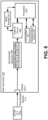
- Figure 5 shows the test instrument 100 according to an example.
- the test instrument 100 includes optical port 1 connected to fiber optic cables in an ODN.
- the test instrument 100 is connected to the test point 105a shown in figure 2 , which may include an open port in splitter 121.
- GPON ONU 103b is connected and disconnected, and the test instrument 100 receives, via the optical port 1, downstream signals 110 from GPON OLT 102a during the activation process to determine ONU information for GPON ONU 103b.
- the test instrument 100 is a termination mode device.
- Optical port 1 can receive upstream or downstream signals transmitted between GPON OLT 102a and GPON ONU 103b.
- downstream signals 110 are shown as being captured by the test instrument 100.
- the test instrument 100 may have more than one optical port.
- the downstream receiver 506 may include a filter 511 to pass desired wavelengths, a photodetector 512 to convert the received downstream optical signals 110 to electric signals, a power meter 515 to measure power levels and loss, a clock data recovery (CDR) circuit 514 to recover clock data from the electrical signal fed to the capture circuit 520, and other components to perform other functions.
- a filter 511 to pass desired wavelengths
- a photodetector 512 to convert the received downstream optical signals 110 to electric signals
- a power meter 515 to measure power levels and loss
- a clock data recovery (CDR) circuit 514 to recover clock data from the electrical signal fed to the capture circuit 520, and other components to perform other functions.
- CDR clock data recovery
- the power meter 515 may measure peak and/or an average optical power, and may include amplifiers connected to a peak/average signal detector. Many types of amplifiers may be used.
- the test instrument 100 may include a user interface 521 to receive user input and to display information, such as power levels, loss, ONU information discussed herein, etc. For example, optical power level of the downstream traffic may be displayed together with the ONU information of the GPON ONU 103b.
- the user interface 521 may include a display, which may include a touch screen display, a keyboard, or other type of known user interface.
- the decoupling and recoupling of GPON ONU 103b initiates the activation process between GPON OLT 102a and GPON ONU 103b.
- the activation process may correspond to a communication standard used by a particular PON.
- GPON ONU 103b may transmit its ONU serial number to GPON OLT 102a for example to announce its presence, and GPON OLT 102a may respond by transmitting a message that includes the ONU identifier, the ONU serial number, the OLT ID and the ONU ID and other information downstream.
- the test instrument 100 captures the ONU information in the message transmitted in the downstream signal.
- the output of the downstream receiver 506 may include a digital data stream (e.g., bit stream) of bytes in the downstream signals 110.
- the capture circuit 520 captures the bytes of the downstream signals 110 during the activation process.
- the captured bytes include the ONU identifier, the ONU serial number, the OLT ID and the ONU ID.
- the capture circuit 520 extracts this information, thereby identifying the link that was disconnected as the link between GPON OLT 102a and GPON ONU 103b, and stores this information in the data storage 551.
- the data storage 551 may store any information captured from the downstream signals 110.
- the data storage 551 may store power level measurements or any other measurements taken by the test instrument 100.
- the stored information may be displayed and/or communicated via communications interface 522, such as WiFi, Ethernet, Bluetooth, USB, etc., to another device or system.
- the capture circuit 520 starts and stops saving the bytes of the downstream signals 110 to the data storage 551.
- the conditions of when to start and stop saving the bytes may be derived from data patterns found in the data stream, e.g., bytes identifying an ONU-ID message, and may also utilize other signals provided from processor 550.
- the processor 550 controls the test process, including the execution of the ONU assignment determination test, and performs data processing on the captured data.
- the processor 550 may also display information via the user interface 521 and transmit/receive data via the communications interface 522.
- the hardware of the test instrument 100 including the processor 550, may include a hardware processor, microcontroller, a digital signal processor (DSP), an application specific integrated circuit (ASIC), a field programmable gate array (FPGA) or other programmable logic device, discrete gate or transistor logic, discrete hardware components, or any combination thereof designed to perform the functions and methods described herein.
- DSP digital signal processor
- ASIC application specific integrated circuit
- FPGA field programmable gate array
- one or more of the functions and steps of the methods may be performed by the processor 550 or other hardware executing machine readable instructions stored in a non-transitory computer readable medium, such as the data storage 551, which may comprise RAM (random access memory), ROM (read only memory), EPROM (erasable, programmable ROM), EEPROM (electrically erasable, programmable ROM), hard drives, flash memory, or other types of storage devices, which may be volatile and/or nonvolatile.
- a non-transitory computer readable medium such as the data storage 551, which may comprise RAM (random access memory), ROM (read only memory), EPROM (erasable, programmable ROM), EEPROM (electrically erasable, programmable ROM), hard drives, flash memory, or other types of storage devices, which may be volatile and/or nonvolatile.
- PON systems e.g., G-PON, XGS-PON, NG-PON2, EPON, 10G EPON, etc.
- the filter 511 in downstream receiver 506 may include multiple filters to capture wavelengths for the different PON systems.
- the downstream receiver 506 can capture downstream signals for OLTs of different PONs simultaneously.
- the test instrument 100 may include other components that are not shown but are known in the art.
- Figure 6 shows a method 600 that may be performed by the test instrument 100. Steps of the method 600 and other methods described herein may be performed in orders other than shown and described or at the same time.
- the test instrument 100 can determine ONU information from downstream messages broadcasted from an OLT during an activation process of an ONU.
- An ONU may communicate with the OLT according to a communication standard which sets forth the message exchange between the OLT and ONU during the activation process.
- the communication standard may include the ITU-T G.984.3 communication standard for a gigabit-capable passive optical network (G-PON): Transmission convergence layer specification.
- the message exchange between the OLT and OLU during the activation process according to the G.984.3 communication standard includes the exchange of physical layer operation and maintenance (PLOAM) messages.
- PLOAM physical layer operation and maintenance
- Figures 6 shows a method for determining ONU information, which may be performed by the test instrument 100. Also, the test instrument 100 can measure power levels and other signal parameters of received optical signals.
- the test instrument 100 starts execution of the ONU assignment determination test, which can determine a one-to-one assignment of an ONU to an OLT in a PON.
- Starting execution of the ONU assignment determination test may include a user selecting the ONU assignment determination test via the user interface 521 to cause the test to be started.
- the test instrument 100 may be operable to run multiple different tests on a PON, and the user, e.g., a technician, may select the ONU assignment determination test via the user interface 521 from among the different tests that the test instrument 100 can perform.
- the test instrument 100 displays instructions on a display of the user interface 521.
- the instructions include instructions that cause an activation process between an ONU and an OLT to be performed.
- the instructions may instruct a user to disconnect and reconnect an ONU, such as GPON ONU 103b, after connecting the test instrument 100 to a test point, such as test point 105a. This causes the activation process to be performed between GPON OLT 102a and GPON ONU 103b.
- the instructions may instruct a user to connect the test instrument 100 to a test point via an optical coupler, such as described with respect to figures 3 and 4 . This causes an ONU to be disconnected and reconnected which invokes the activation process.
- the test instrument 100 captures ONU information from a downstream signal received from an OLT during the activation process.
- the ONU information includes the OLT ID, the ONU serial number, and the ONU ID.
- the ONU information 130 may also include the ONU status, such as activated or deactivated.
- the PON type may be determined from the OLT ID.
- the ONU information may be captured during a serial number state of the activation process.
- the capture circuit 520 may capture the ONU information from the downstream signals from the OLT. For example, during the activation process, the ONU sends its serial number to the OLT, such as in a Serial_Number_ONU message. The OLT receives the Serial_Number_ONU message and extracts the ONU serial number. Then, the OLT assigns an ONU-ID to the ONU and sends an Assign_ONU-ID message to the ONU, including the serial number of the ONU and the ONU-ID assigned by the OLT. Also, the OLT ID is captured and other ONU information is captured. For example, the OLT ID is captured from a downstream frame transmitted from the OLT. According to the GPON protocol, a downstream frame includes a PCBd (physical control block downstream). The PCBd includes the PLOAMd (physical layer operation, administration and maintenance downstream), and the PLOAMd includes the PON ID (passive optical network identification). The PON-ID includes the OLT ID (optical line termination identification).
- PCBd physical control
- Bytes of the Assign_ONU-ID message are shown in figure 7 .
- Byte 2 includes a pattern of bits that indicates that the message is an Assign_ONU-ID message.
- Byte 3 includes the ONU-ID and bytes 4-11 include the serial number of the ONU 103. Captured ONU information and other information is stored in data storage 551.
- the test instrument 100 determines the ONU information captured by the capture circuit 520. This may include the processor 550 retrieving the captured ONU information from the data storage 551.
- the test instrument 100 displays ONU information determined from the captured information on a display of the user interface 521.
- the ONU information includes the one-to-one assignment of the ONU to the OLT.
- the processor 550 displays the ONU information including the OLT ID, the ONU serial number, and the ONU ID.
- the displayed information may also include ONU status, such as activated or deactivated.
- the displayed information may also include the PON type.
- the test instrument 100 may determine the PON type from the PON ID.
- the PON ID indicates the ODN architecture and its class, as well as the source of the reported power.
- the test instrument 100 may also compare at least one the ONU serial number and the OLT ID captured from downstream signals during the activation process to a known ONU serial number and OLT ID for a customer.
- the test instrument 100 can display an indication of whether a match has been found. For example, a service ticket may be generated for a customer to switch the customer to a new service provider connected to a different OLT.
- the serial number of an ONU at the customer premises is known and stored in the test instrument 100.
- the serial number of the customer premises ONU is compared to the ONU serial number determined from the ONU information captured during the test. If it is a match, the test instrument 100 displays an indication that a match is identified. Then, the technician knows that the link is the correct link of the customer and the technician can connect the ONU to the new OLT as needed.
- the ONU 103 may go through various states. In an initial state, the ONU 103 is powered up, and in a standby state, the ONU 103 is waiting for the PON parameters from the OLT 102. In a serial number state, the ONU 103 makes itself known to the OLT 102 by sending its serial number to the OLT 102 and the ONU 103 receives the Assign_ONU-ID message with the ONU identifiers. In a ranging state, the ONU 103 synchronizes its upstream frame clock based on its assigned equalization delay. The ONU information including the OLT ID and the ONU serial number may be captured from the downstream signals 110 from the OLT 102 in the serial number state.
- ONU information may be captured from downstream signals transmitted from an OLT when communications standards other than the GPON communications standards are implemented in the PON.
- the ONU information may be captured from downstream signals for any communications standard that includes transmission of downstream messages that include the ONU information during an activation process.
Landscapes
- Engineering & Computer Science (AREA)
- Computer Networks & Wireless Communication (AREA)
- Physics & Mathematics (AREA)
- Electromagnetism (AREA)
- Signal Processing (AREA)
- Small-Scale Networks (AREA)
- Optical Communication System (AREA)
Priority Applications (2)
| Application Number | Priority Date | Filing Date | Title |
|---|---|---|---|
| EP22306700.0A EP4373011A1 (de) | 2022-11-18 | 2022-11-18 | Testinstrument für ein optisches netzwerk mit test für eine optische netzwerkeinheit und zuweisung eines optischen leitungsendgeräts |
| US18/366,519 US20240171273A1 (en) | 2022-11-18 | 2023-08-07 | Optical network test instrument including testing for optical network unit and optical line terminal assignment |
Applications Claiming Priority (1)
| Application Number | Priority Date | Filing Date | Title |
|---|---|---|---|
| EP22306700.0A EP4373011A1 (de) | 2022-11-18 | 2022-11-18 | Testinstrument für ein optisches netzwerk mit test für eine optische netzwerkeinheit und zuweisung eines optischen leitungsendgeräts |
Publications (1)
| Publication Number | Publication Date |
|---|---|
| EP4373011A1 true EP4373011A1 (de) | 2024-05-22 |
Family
ID=84421648
Family Applications (1)
| Application Number | Title | Priority Date | Filing Date |
|---|---|---|---|
| EP22306700.0A Pending EP4373011A1 (de) | 2022-11-18 | 2022-11-18 | Testinstrument für ein optisches netzwerk mit test für eine optische netzwerkeinheit und zuweisung eines optischen leitungsendgeräts |
Country Status (2)
| Country | Link |
|---|---|
| US (1) | US20240171273A1 (de) |
| EP (1) | EP4373011A1 (de) |
Citations (2)
| Publication number | Priority date | Publication date | Assignee | Title |
|---|---|---|---|---|
| EP2846479A1 (de) * | 2013-08-07 | 2015-03-11 | JDSU Deutschland GmbH | Prüfung eines passiven optischen Netzwerks |
| EP3112838A1 (de) * | 2015-06-30 | 2017-01-04 | Viavi Solutions Deutschland GmbH | Optisches netzwerktestinstrument mit identifikatoraufnahmefähigkeit für optische netzwerkeinheit aus nachgeschalteten signalen |
-
2022
- 2022-11-18 EP EP22306700.0A patent/EP4373011A1/de active Pending
-
2023
- 2023-08-07 US US18/366,519 patent/US20240171273A1/en active Pending
Patent Citations (2)
| Publication number | Priority date | Publication date | Assignee | Title |
|---|---|---|---|---|
| EP2846479A1 (de) * | 2013-08-07 | 2015-03-11 | JDSU Deutschland GmbH | Prüfung eines passiven optischen Netzwerks |
| EP3112838A1 (de) * | 2015-06-30 | 2017-01-04 | Viavi Solutions Deutschland GmbH | Optisches netzwerktestinstrument mit identifikatoraufnahmefähigkeit für optische netzwerkeinheit aus nachgeschalteten signalen |
Also Published As
| Publication number | Publication date |
|---|---|
| US20240171273A1 (en) | 2024-05-23 |
Similar Documents
| Publication | Publication Date | Title |
|---|---|---|
| US10742317B2 (en) | Optical network test instrument including optical network unit identifier capture capability from downstream signals | |
| US9847832B2 (en) | Testing a passive optical network | |
| US10454574B2 (en) | System and method for performing in-service optical network certification | |
| US11742943B2 (en) | System and method for performing in-service optical network certification | |
| US8180223B2 (en) | System and method for extending reach in a passive optical network | |
| US8655166B2 (en) | System and method for performing in-service optical fiber network certification | |
| US20090263122A1 (en) | Method and apparatus for network diagnostics in a passive optical network | |
| KR100738559B1 (ko) | Epon 시스템의 대역폭 설정 방법 및 그 장치 | |
| US20160269115A1 (en) | Hybrid fiber/cu distribution point with external onu-to-dsl conversion unit | |
| US9002199B2 (en) | Apparatus and method for monitoring optical line | |
| US20050198272A1 (en) | System, method, and apparatus for connectivity testing | |
| US20170164076A1 (en) | Optical network with small-form-factor optical fiber cross-connect module | |
| US8565599B2 (en) | System and method for transmitting optical markers in a passive optical network system | |
| EP3975580B1 (de) | Verfahren zur bestimmung der verbindung optischer netzwerkendgeräte, vorrichtung und system | |
| EP4373011A1 (de) | Testinstrument für ein optisches netzwerk mit test für eine optische netzwerkeinheit und zuweisung eines optischen leitungsendgeräts | |
| Premadi et al. | Optical Managing Project--Effectively Survivability and Monitoring System | |
| Hajduczenia et al. | Fault discovery protocol (FDP) for passive optical networks (PONs) |
Legal Events
| Date | Code | Title | Description |
|---|---|---|---|
| PUAI | Public reference made under article 153(3) epc to a published international application that has entered the european phase |
Free format text: ORIGINAL CODE: 0009012 |
|
| STAA | Information on the status of an ep patent application or granted ep patent |
Free format text: STATUS: THE APPLICATION HAS BEEN PUBLISHED |
|
| AK | Designated contracting states |
Kind code of ref document: A1 Designated state(s): AL AT BE BG CH CY CZ DE DK EE ES FI FR GB GR HR HU IE IS IT LI LT LU LV MC ME MK MT NL NO PL PT RO RS SE SI SK SM TR |