EP4372948B1 - Computer-implemented method, computer-implemented tool and power plant control device for energy balancing solar power plants and a solar power plant system - Google Patents
Computer-implemented method, computer-implemented tool and power plant control device for energy balancing solar power plants and a solar power plant system Download PDFInfo
- Publication number
- EP4372948B1 EP4372948B1 EP22208077.2A EP22208077A EP4372948B1 EP 4372948 B1 EP4372948 B1 EP 4372948B1 EP 22208077 A EP22208077 A EP 22208077A EP 4372948 B1 EP4372948 B1 EP 4372948B1
- Authority
- EP
- European Patent Office
- Prior art keywords
- est
- measurement signal
- power production
- gmt
- irradiation
- Prior art date
- Legal status (The legal status is an assumption and is not a legal conclusion. Google has not performed a legal analysis and makes no representation as to the accuracy of the status listed.)
- Active
Links
Images


Classifications
-
- H—ELECTRICITY
- H02—GENERATION; CONVERSION OR DISTRIBUTION OF ELECTRIC POWER
- H02J—ELECTRIC POWER NETWORKS; CIRCUIT ARRANGEMENTS OR SYSTEMS FOR SUPPLYING OR DISTRIBUTING ELECTRIC POWER; SYSTEMS FOR STORING ELECTRIC ENERGY
- H02J3/00—Circuit arrangements for AC mains or AC distribution networks
- H02J3/38—Arrangements for feeding a single network from two or more generators or sources in parallel; Arrangements for feeding already energised networks from additional generators or sources in parallel
- H02J3/381—Dispersed generators
-
- H—ELECTRICITY
- H02—GENERATION; CONVERSION OR DISTRIBUTION OF ELECTRIC POWER
- H02J—ELECTRIC POWER NETWORKS; CIRCUIT ARRANGEMENTS OR SYSTEMS FOR SUPPLYING OR DISTRIBUTING ELECTRIC POWER; SYSTEMS FOR STORING ELECTRIC ENERGY
- H02J3/00—Circuit arrangements for AC mains or AC distribution networks
- H02J3/38—Arrangements for feeding a single network from two or more generators or sources in parallel; Arrangements for feeding already energised networks from additional generators or sources in parallel
- H02J3/46—Controlling the sharing of generated power between the generators, sources or networks
-
- H—ELECTRICITY
- H02—GENERATION; CONVERSION OR DISTRIBUTION OF ELECTRIC POWER
- H02J—ELECTRIC POWER NETWORKS; CIRCUIT ARRANGEMENTS OR SYSTEMS FOR SUPPLYING OR DISTRIBUTING ELECTRIC POWER; SYSTEMS FOR STORING ELECTRIC ENERGY
- H02J3/00—Circuit arrangements for AC mains or AC distribution networks
- H02J3/004—Generation forecast, e.g. methods or systems for forecasting future energy generation
-
- H—ELECTRICITY
- H02—GENERATION; CONVERSION OR DISTRIBUTION OF ELECTRIC POWER
- H02J—ELECTRIC POWER NETWORKS; CIRCUIT ARRANGEMENTS OR SYSTEMS FOR SUPPLYING OR DISTRIBUTING ELECTRIC POWER; SYSTEMS FOR STORING ELECTRIC ENERGY
- H02J2101/00—Supply or distribution of decentralised, dispersed or local electric power generation
- H02J2101/20—Dispersed power generation using renewable energy sources
- H02J2101/22—Solar energy
- H02J2101/24—Photovoltaics
-
- H—ELECTRICITY
- H02—GENERATION; CONVERSION OR DISTRIBUTION OF ELECTRIC POWER
- H02J—ELECTRIC POWER NETWORKS; CIRCUIT ARRANGEMENTS OR SYSTEMS FOR SUPPLYING OR DISTRIBUTING ELECTRIC POWER; SYSTEMS FOR STORING ELECTRIC ENERGY
- H02J2103/00—Details of circuit arrangements for mains or AC distribution networks
- H02J2103/30—Simulating, planning, modelling, reliability check or computer assisted design [CAD] of electric power networks
Definitions
- the invention refers to a computer-implemented method for energy balancing solar power plants according to the preamble of claim 1, a computer-implemented tool for energy balancing solar power plants according to the preamble of claim 6, a power plant control device for energy balancing solar power plants according to the preamble of claim 11 and a solar power plant system according to the preamble of claim 12.
- the objective is further solved based on a computer-implemented tool defined in the preamble of claim 6 by the features in the characterizing part of claim 6.
- the objective is solved furthermore based on a power plant control device defined in the preamble of claim 11 by the features in the characterizing part of claim 11.
- the objective is solved moreover based on a solar power plant system defined in the preamble of claim 12 by the features in the characterizing part of claim 12.
- a first primary step “S1 p " the power production measurement signal "P(t)” with the set of power production measurement values “P(t 0 )” to “P(t n )” and the irradiation measurement signal “I(t)” with the set of irradiation measurement values “I(t 0 )” to “I(t n )” are fed to the curve matching algorithm.
- a candidate set for good matching to the recording time "[t 0 to t n ]" are set.
- a scaling factor "s" by solving a first optimization problem to min s ⁇ t ⁇ candidate set P t ⁇ sI t 2 is calculated.
- a sixth primary step "S6 p " the at least one good matching time corresponding to the candidate set is outputted after the last iteration of the fifth primary step " S5 p ".
- FIGURE 4 The result of this iterative approach is depicted in FIGURE 4 .
- the fitting algorithm is preferably a robust least squares fit algorithm to generate the parameter set " K " with the at least one parameter "[k 0 , k 1 , ...]” is preferably also iterative based, in which following secondary steps “ S1 s “ to " S5 s " of the robust least squares fit algorithm are carried out, wherein the steps " S2 s " to "S4 s " are done iteratively.
- a further third secondary step “ S3 s " the further parameter set "K*” is used to calculate a set of quadratic deviations as [(P(t) - P est (t,K*)) 2 ... ] for all "t ⁇ good matching times". Then also in this third secondary step “S3 s " a percentage share of the times, e.g. 10%, from the good matching times corresponding to the highest values in the set of quadratic deviations are eliminated.
- FIGURE 5 The result of this iterative approach is depicted in FIGURE 5 .
- FIGURES 1 to 5 show:
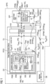
- FIGURE 1 shows a solar power plant system SPPS for energy balancing a solar power plant SPP including various components such as inverters INV, "Photo-Voltaic ⁇ PV>” generators preferably designed as PV strings PVS and measurement devices etc., as an “implementation-concept".
- inverters INV inverters
- Photo-Voltaic ⁇ PV> generators preferably designed as PV strings PVS and measurement devices etc., as an “implementation-concept”.
- the drop of performance corresponds when cumulated over a time frame in a loss of energy. As stated in the beginning of the present application there are more reasons for such energy losses, which are useful to be quantified in the course of energy balancing the solar power plant SPP.
- the depicted solar power plant system SPPS includes, besides the solar power plant SPP with the cited components INV, PVS, MDV as a central component for energy balancing the solar power plant SPP a power plant control device PPCD and moreover a database DB, which is preferably designed as a data cloud.
- the power plant control device PPCD includes a control unit CU and a power plant interface PPIF, wherein the corresponding control of the solar power plant SPP is carried out by the control unit CU via the power plant interface PPIF.
- the control unit CU includes a computer-implemented tool CIT which is implemented as a sub-unit in the control unit CU.
- the computer-implemented tool CIT is a computer-program-product which is preferably designed as an application software, called as APP, that allows, when it is implemented, to perform special tasks. So, in the present case of the control unit CU, where the computer-program-product respectively the APP is implemented, the computer-implemented tool CIT is used for energy balancing the solar power plant SPP.
- the computer-implemented tool CIT comprises a non-transitory, processor-readable storage medium STM, in which processor-readable program-instructions of a program module PGM are stored.
- This program module PGM is used for energy balancing the solar power plant SPP.
- the computer-implemented tool CIT comprises a processor PRC connected with the storage medium STM executing the processor-readable program-instructions of the program module PGM to energy balance the solar power plant SPP, wherein the program module PGM and the processor PRC form an energy balancing engine EBE for doing this energy balancing.
- FIGURE 2 shows a solar power plant system SPPS for energy balancing a solar power plant SPP including various components such as inverters INV, "Photo-Voltaic ⁇ PV>” generators preferably designed as PV strings PVS and measurement devices etc., as a “functional-unit-concept".
- inverters INV inverters
- Photo-Voltaic ⁇ PV> generators preferably designed as PV strings PVS and measurement devices etc., as a “functional-unit-concept”.
- the drop of performance corresponds again when cumulated over a time frame in a loss of energy. As stated in the beginning of the present application there are more reasons for such energy losses, which are useful to be quantified in the course of energy balancing the solar power plant SPP.
- the depicted solar power plant system SPPS includes again, besides the solar power plant SPP with the cited components INV, PVS, MDV as a central component for energy balancing the solar power plant SPP a power plant control device PPCD and moreover a database DB, which is preferably designed as a data cloud.
- the power plant control device PPCD includes a control unit CU and a power plant interface PPIF, wherein the corresponding control of the solar power plant SPP is carried out by the control unit CU via the power plant interface PPIF.
- the control unit CU does not include the computer-implemented tool CIT. Instead, the Computer-implemented tool CIT forms a functional unit FTU with the control unit CU.
- This functional unit FTU is preferably designed such that the Computer-implemented tool CIT is either loadable into the control unit CU according to the depiction in the FIGURE 2 or forms either (not depicted in the FIGURE 2 ) a cloud-based, centralized platform, e.g. a server, for the power plant control device PPCD or a decentralized platform, e.g. a server, for the power plant control device PPCD with a mutual access within the functional unit between the control unit CU and the Computer-implemented tool CIT.
- a cloud-based, centralized platform e.g. a server
- a decentralized platform e.g. a server
- the computer-implemented tool CIT is again a computer-program-product which in the case upload-functionality is again preferably designed as an application software, called as APP, that allows, when it is implemented, to perform special tasks. So, in the present case of the control unit CU, when the computer-program-product respectively the APP is uploaded, the power plant control device PPCD with uploaded computer-implemented tool CIT is used for detecting the power production degradation of the solar power plant SPP.
- the computer-implemented tool CIT comprises again a non-transitory, processor-readable storage medium STM, in which processor-readable program-instructions of a program module PGM are stored.
- This program module PGM is used for energy balancing the solar power plant SPP.
- the computer-implemented tool CIT comprises again a processor PRC connected with the storage medium STM executing the processor-readable program-instructions of the program module PGM to energy balance the solar power plant SPP, wherein the program module PGM and the processor PRC form again an energy balancing engine EBE for doing this energy balancing.
- the energy balancing for both concepts, the "implementation-concept” and the “functional-unit-concept” is generally based on various measurements MM (cf. FIGURE 3 ).
- EATP energy accounting time period
- the measurement signals IMS, PMS with the corresponding measured values SIMV, SPPMV are measured independently or time shifted from the energy balancing process itself, they can be stored meanwhile or intermediately in the database DB before they are inputted into, supplied to or retrieved from the processor PRC via the power plant interface PPIF and the control unit CU. Otherwise they are inputted directly into, supplied directly to or retrieved directly from the processor PRC via the power plant interface PPIF and the control unit CU.
- both parameter set "K” PMS and the estimated power production measurement signal "P est (t, K)" PPMS est can be stored preferably in the database DB.
- the energy balancing engine EBE formed by the processor PRC and the program module PGM is designed such that a control information CINF is generated and used to control reductions of impacts concerning the calculated energy loss E loss on the solar power plant SPP.
- the energy balancing engine EBE formed by the processor PRC and the program module PGM is designed advantageously such that the curve matching algorithm CMA (cf. FIGURE 3 ) to identify idf the at least one good matching time GMT is preferably iterative based, in which following primary steps "S1 p " to "S6 p " of the curve matching algorithm CMA (cf. FIGURE 3 ) are carried out, wherein the steps "S3 p " to "S5 p " are done iteratively.
- a first primary step “S1 p " the power production measurement signal "P(t)” PPMS with the set of power production measurement values “P(t 0 )” to “P(t n )” SPPMV and the irradiation measurement signal "I(t)” IMS with the set of irradiation measurement values "I(t 0 )” to "I(t n )” SIMV are fed to the curve matching algorithm CMA (cf. FIGURE 3 ).
- a candidate set CS GM for good matching to the recording time "[t 0 to t n ]" are set.
- a scaling factor "s" SF by solving a first optimization problem OPP1 to min s ⁇ t ⁇ candidate set P t ⁇ sI t 2 is calculated.
- time points from the candidate set for good matching CS GM are included, wherein all of the following criteria between a "P(t)"-value and a “sI(t)"-value for "t” in the recording time "[t 0 to t n ]" are satisfied
- a sixth primary step “S6 p” the at least one good matching time GMT corresponding to the candidate set CS GM is outputted after the last iteration of the fifth primary step " S5 p ".
- the energy balancing engine EBE formed by the processor PRC and the program module PGM is designed advantageously such that the robust least squares fit algorithm RLSFA (cf. FIGURE 3 ) as an advantageous form of the fitting algorithm FA to generate grt the parameter set "K” PMS with the at least one parameter "[k 0 , k 1 , ...]” PM is preferably also iterative based, in which following secondary steps “S1 s “ to "S5 s " of the robust least squares fit algorithm RLFSA (cf. FIGURE 3 ) are carried out, wherein the steps "S2 s " to "S4 s " are done iteratively.
- RLSFA robust least squares fit algorithm
- a further third secondary step “S3 s” the further parameter set "K*" PMS' is used to calculate a set of quadratic deviations SQD as [(P(t) - P est (t,K*)) 2 ... ] for all "t ⁇ good matching times". Then also in this third secondary step “S3 s " a percentage share of the times, e.g. 10%, from the good matching times corresponding to the highest values in the set of quadratic deviations SQD are eliminated.
- a historical parameter set "K” may be used to screen for partial failures of the component. If historical parameter set "K” jumped to lower values and remained at such low values until to the robust least squares fit algorithm evaluation, this means that a partial failure is present in the solar power plant during the robust least squares fit algorithm evaluation. In this case, the last parameter set "K" before the jump should be used to also estimate the energy losses due to constant partial failures, as well as intermittent failures.
Landscapes
- Engineering & Computer Science (AREA)
- Power Engineering (AREA)
- Management, Administration, Business Operations System, And Electronic Commerce (AREA)
- Supply And Distribution Of Alternating Current (AREA)
Description
- The invention refers to a computer-implemented method for energy balancing solar power plants according to the preamble of claim 1, a computer-implemented tool for energy balancing solar power plants according to the preamble of claim 6, a power plant control device for energy balancing solar power plants according to the preamble of claim 11 and a solar power plant system according to the preamble of claim 12.
- When operating solar power plants there are many reasons for power losses in the solar power plants by <i> "Photo-Voltaic <PV>" generators, such as failures of components such as inverters, PV strings, measurement devices etc., <ii> curtailment with a controlled reduction of solar power production, <iii> clipping when a "Direct Current <DC>" power output of the PV strings is higher than the inverter power rating) or <iv> shading etc.
- For this reason it is useful to quantify how much electrical energy, which means how much money, would be lost due to a reduced power output of a solar power plant. This enables an adjustment of a solar power plant control, an adaption of maintenance activity etc.
- Up to now, this quantification problem was solved by manual observation of solar power plant production values and comparison with production values in previous months and/or years.
- It is an objective of the invention to propose a computer-implemented method, a computer-implemented tool and a power plant control device for energy balancing solar power plants as well as a solar power plant system, by which energy losses of the solar power plants are determined and reliably quantified so that their impacts on energy outputs of the solar power plants could be reduced.
- This objective is solved based on a computer-implemented method defined in the preamble of claim 1 by the features in the characterizing part of claim 1.
- The objective is further solved based on a computer-implemented tool defined in the preamble of claim 6 by the features in the characterizing part of claim 6.
- The objective is solved furthermore based on a power plant control device defined in the preamble of claim 11 by the features in the characterizing part of claim 11.
- The objective is solved moreover based on a solar power plant system defined in the preamble of claim 12 by the features in the characterizing part of claim 12.
- The main idea of the invention according to the claims 1, 6, 11 and 12 in order to do an energy balancing of solar power plants, when for an energy accounting time period of a solar power plant, in which over a recording time "[t0 to tn]" with

- match for the recording time "[t0 to tn]" the power production measurement signal "P(t)" to the irradiation measurement signal "I(t)" by using a curve matching algorithm to identify based on the set of power production measurement values "P(t0)" to "P(tn)" and the set of irradiation measurement values "I(t0)" to "I(tn)" being collected at least one good matching time, in which the power production measurement signal "P(t)" and the irradiation measurement signal "I(t)" match optimally through a minimum signal distance,
- run a fitting algorithm, in particular a robust least squares fit algorithm, for the at least one good matching time and based <i> regarding a "good matching time"-related part of the power production measurement signal "PGMT(t)" (PPMSGMT) on a subset of the set of power production measurement values "Pi(to)" to "Pi(tn)" and <ii> regarding a "good matching time"-related part of the irradiation measurement signal "IGMT(t)" on a subset of the set of irradiation measurement values "I(t0)" to "I(tn)" (SIMVSS) to generate according to an estimated power production measurement signal "Pest (t, K)" defined as a function "f(I(t),K)" with "Pest (t, K)=f(I(t), K=[k0, k1, ...])" a parameter set "K" with at least one parameter "[k0, k1, ...]", in which when running the fitting algorithm a deviation between the power production measurement signal "P(t)" and the estimated power production measurement signal "Pest(t, K)" is minimized by tuning or changing the parameter set "K",
- calculate for the recording time "[t0 to tn]" based on <1> the set of power production measurement values "P(t0)" to "P(tn)", <2> the set of irradiation measurement values "I(t0)" to "I(tn)" (SIMV) and <3> the generated parameter set "K" with the at least one parameter "[k0, k1, ...]" the estimated power production measurement signal "Pest(t, K)" in order to determine a value for an energy loss by an integral calculation of a power difference

- Further advantages arise out of additional developments of the invention according to the independent claims.
- I. So, according to the claims 2 and 7 the curve matching algorithm to identify the at least one good matching time is preferably iterative based, in which following primary steps "S1p " to "S6p " of the curve matching algorithm are carried out, wherein the steps "S3p " to "S5p " are done iteratively.
- In a first primary step "S1p" the power production measurement signal "P(t)" with the set of power production measurement values "P(t0)" to "P(tn)" and the irradiation measurement signal "I(t)" with the set of irradiation measurement values "I(t0)" to "I(tn)" are fed to the curve matching algorithm.
- In a next second primary step "S2p " a candidate set for good matching to the recording time "[t0 to tn]" are set.
- In a further third primary step "S3p" a scaling factor "s" by solving a first optimization problem to

- Then, in a fourth primary step "S4p " time points from the candidate set for good matching are included, wherein all of the following criteria between a "P(t)"-value and a "sI(t)"-value for "t" in the recording time "[t0 to tn]" are satisfied
- A deviation between the values is smaller than a first threshold value
- A difference of variabilities of the values is smaller than a second threshold value.
- Moreover, in a fifth primary step "S5p" following the mentioned iteration it is going back to the third primary step "S3p" until the candidate set for good matching (CSGM) remains unchanged according to the fourth primary step "S4p ".
- Finally, in a sixth primary step "S6p" the at least one good matching time corresponding to the candidate set is outputted after the last iteration of the fifth primary step "S5p ".
- The result of this iterative approach is depicted in
FIGURE 4 . - II. So, according to the claims 3 and 8 the fitting algorithm is preferably a robust least squares fit algorithm to generate the parameter set "K" with the at least one parameter "[k0, k1, ...]" is preferably also iterative based, in which following secondary steps "S1s " to "S5s " of the robust least squares fit algorithm are carried out, wherein the steps "S2s " to "S4s" are done iteratively.
- In a first secondary step "S1s" the "good matching time"-related part of the power production measurement signal "PGMT(t)" with the subset of the set of power production measurement values "P(t0)" to "P(tn)" and the "good matching time"-related part of the irradiation measurement signal "IGMT(t)" on the subset of the set of irradiation measurement values "I(t0)" to "I(tn)" are fed into the robust least squares fit algorithm.
- In a next second secondary step "S2s" a further parameter set "K*" by solving a second optimization problem to

- In a further third secondary step "S3s " the further parameter set "K*" is used to calculate a set of quadratic deviations as [(P(t) - Pest(t,K*))2 ... ] for all "t∈ good matching times". Then also in this third secondary step "S3s" a percentage share of the times, e.g. 10%, from the good matching times corresponding to the highest values in the set of quadratic deviations are eliminated.
- Moreover, in a fourth secondary step "S4s" following the mentioned iteration it is going back to the second secondary step "S2s" until a specified number of iterations, e.g., 3 iterations, is achieved.
- Finally, in a fifth secondary step "S5s" the parameter set "K" corresponding to the further parameter set "K*" is outputted after the last iteration of the fourth secondary step "S4s ".
- The result of this iterative approach is depicted in
FIGURE 5 . - III. So, according to the claims 4 and 9 the function "f(I(t),K)" with K=[k0, k1, ...] the estimated power production measurement signal "Pest(t, K)" is calculated by is preferably a linear function "Pest(t, k0)= I(t)" or a quadratic function "Pest(t, k0, k1)= k0 I(t) + k1 I(t)2".
- IV. So, according to the claims 5 and 10 it is beneficial that a control information is generated and used to control reductions of impacts concerning the calculated energy loss on the solar power plant.
- Moreover, advantageous further developments of the invention arise out of the following description of a preferred embodiment of the invention according to
FIGURES 1 to 5 . They show: -
FIGURE 1 a solar power plant system for energy balancing solar power plants as an "implementation-concept", -
FIGURE 2 a solar power plant system for energy balancing solar power plants as a "functional-unit-concept", -
FIGURE 3 a flowchart of a process to determine an energy loss in the course of energy balancing solar power plants, -
FIGURE 4 a visualizing chart depicting an irradiation measurement signal "I(t)" and a power production measurement signal "P(t)", -
FIGURE 5 a visualizing chart depicting a power production measurement signal "P(t)" and an estimated power production measurement signal "Pest(t, K)". -
FIGURE 1 shows a solar power plant system SPPS for energy balancing a solar power plant SPP including various components such as inverters INV, "Photo-Voltaic <PV>" generators preferably designed as PV strings PVS and measurement devices etc., as an "implementation-concept". When operating the solar power plant SPP and at least one the these component fails during operation this is reflected in a drop of performance concerning a generated power P of the solar power plant SPP from an irradiation I which is hitting the solar power plant SPP and preferably at least one of a "Global Horizontal Irradiance <GHI>" and a "Plan Of Array Irradiance <POA Irradiance>". - The drop of performance corresponds when cumulated over a time frame in a loss of energy. As stated in the beginning of the present application there are more reasons for such energy losses, which are useful to be quantified in the course of energy balancing the solar power plant SPP.
- The depicted solar power plant system SPPS includes, besides the solar power plant SPP with the cited components INV, PVS, MDV as a central component for energy balancing the solar power plant SPP a power plant control device PPCD and moreover a database DB, which is preferably designed as a data cloud.
- One of the usual goals of the power plant control device PPCD is to enable a requested output, e.g. by an electrical consumer being connectable to the solar power plant SPP, of the generated power P. For this goal and the cited purposes the power plant control device PPCD includes a control unit CU and a power plant interface PPIF, wherein the corresponding control of the solar power plant SPP is carried out by the control unit CU via the power plant interface PPIF.
- Furthermore in the context of the balancing task of the solar power plant system SPPS the power plant control device PPCD with the cited two components, the control unit CU and the power plant interface PPIF, is also responsible for energy balancing the solar power plant SPP. Therefore, according to the "implementation-concept" depicted in the
FIGURE 1 the control unit CU includes a computer-implemented tool CIT which is implemented as a sub-unit in the control unit CU. The computer-implemented tool CIT is a computer-program-product which is preferably designed as an application software, called as APP, that allows, when it is implemented, to perform special tasks. So, in the present case of the control unit CU, where the computer-program-product respectively the APP is implemented, the computer-implemented tool CIT is used for energy balancing the solar power plant SPP. - To this end the computer-implemented tool CIT comprises a non-transitory, processor-readable storage medium STM, in which processor-readable program-instructions of a program module PGM are stored. This program module PGM is used for energy balancing the solar power plant SPP. Moreover the computer-implemented tool CIT comprises a processor PRC connected with the storage medium STM executing the processor-readable program-instructions of the program module PGM to energy balance the solar power plant SPP, wherein the program module PGM and the processor PRC form an energy balancing engine EBE for doing this energy balancing.
-
FIGURE 2 shows a solar power plant system SPPS for energy balancing a solar power plant SPP including various components such as inverters INV, "Photo-Voltaic <PV>" generators preferably designed as PV strings PVS and measurement devices etc., as a "functional-unit-concept". Again when operating the solar power plant SPP and at least one the these component fails during operation this is reflected in a drop of performance concerning a generated power P of the solar power plant SPP from an irradiation I which is hitting the solar power plant SPP and preferably at least one of a "Global Horizontal Irradiance <GHI>" and a "Plan Of Array Irradiance <POA Irradiance>". - The drop of performance corresponds again when cumulated over a time frame in a loss of energy. As stated in the beginning of the present application there are more reasons for such energy losses, which are useful to be quantified in the course of energy balancing the solar power plant SPP.
- The depicted solar power plant system SPPS includes again, besides the solar power plant SPP with the cited components INV, PVS, MDV as a central component for energy balancing the solar power plant SPP a power plant control device PPCD and moreover a database DB, which is preferably designed as a data cloud.
- Again one of the usual goals of the power plant control device PPCD is to enable a requested output, e.g. by an electrical consumer being connectable to the solar power plant SPP, of the generated power P. For this goal and the cited purposes the power plant control device PPCD includes a control unit CU and a power plant interface PPIF, wherein the corresponding control of the solar power plant SPP is carried out by the control unit CU via the power plant interface PPIF.
- Furthermore in the context of the balancing task of the solar power plant system SPPS the power plant control device PPCD with the cited two components, the control unit CU and the power plant interface PPIF, is again also responsible for energy balancing the solar power plant SPP. Therefore, according to the "functional-unit-concept" depicted in the
FIGURE 2 the control unit CU does not include the computer-implemented tool CIT. Instead, the Computer-implemented tool CIT forms a functional unit FTU with the control unit CU. This functional unit FTU is preferably designed such that the Computer-implemented tool CIT is either loadable into the control unit CU according to the depiction in theFIGURE 2 or forms either (not depicted in theFIGURE 2 ) a cloud-based, centralized platform, e.g. a server, for the power plant control device PPCD or a decentralized platform, e.g. a server, for the power plant control device PPCD with a mutual access within the functional unit between the control unit CU and the Computer-implemented tool CIT. - In each of cited variants of realization the computer-implemented tool CIT is again a computer-program-product which in the case upload-functionality is again preferably designed as an application software, called as APP, that allows, when it is implemented, to perform special tasks. So, in the present case of the control unit CU, when the computer-program-product respectively the APP is uploaded, the power plant control device PPCD with uploaded computer-implemented tool CIT is used for detecting the power production degradation of the solar power plant SPP.
- To this end the computer-implemented tool CIT comprises again a non-transitory, processor-readable storage medium STM, in which processor-readable program-instructions of a program module PGM are stored. This program module PGM is used for energy balancing the solar power plant SPP. Moreover the computer-implemented tool CIT comprises again a processor PRC connected with the storage medium STM executing the processor-readable program-instructions of the program module PGM to energy balance the solar power plant SPP, wherein the program module PGM and the processor PRC form again an energy balancing engine EBE for doing this energy balancing.
- The energy balancing for both concepts, the "implementation-concept" and the "functional-unit-concept" is generally based on various measurements MM (cf.
FIGURE 3 ). The measurements take place over a recording or measurement time "[t0 to tn]" with
- (i) - by measuring regarding the irradiation I, which is preferably based on a measured plane-of-array irradiation, an irradiation measurement signal "I(t)" IMS - a set of irradiation measurement values "I(t0)" to "I(tn)" SIMV and
- (ii) - by measuring regarding the generated power P, which is preferably based on a measured power of the complete solar power plant SPP, INV, PVS, MDV or at least one part of the cited solar power plant components such as the inverter INV, the "Photo-Voltaic <PV>"-string PVS or the measurement device MDV, a power production measurement signal "P(t)" PPMS - a set of power production measurement values "P(t0)" to "P(tn)" SPPMV.
- Remark: If according to (i) above the "Global Horizontal Irradiance <GHI>" or any other diffuse irradiation can be measured, the irradiation measurement values could be transformed with state-of-the-art methods to the plane-of-array measurements.
- When the measurement signals IMS, PMS with the corresponding measured values SIMV, SPPMV are measured independently or time shifted from the energy balancing process itself, they can be stored meanwhile or intermediately in the database DB before they are inputted into, supplied to or retrieved from the processor PRC via the power plant interface PPIF and the control unit CU. Otherwise they are inputted directly into, supplied directly to or retrieved directly from the processor PRC via the power plant interface PPIF and the control unit CU.
- For doing now based on the described measurements MM (cf.
FIGURE 3 ) the cited energy balancing of the solar power plant SPP - according to a flowchart of a process to determine an energy loss in the course of energy balancing solar power plants inFIGURE 3 - the energy balancing engine EBE formed by the processor PRC and the program module PGM are doing the following: - (1) Matching mtc for the recording time "[t0 to tn]" the power production measurement signal "P(t)" PPMS to the irradiation measurement signal "I(t)" IMS by using a curve matching algorithm CMA (cf.
FIGURE 3 ) to identify idf based on the set of power production measurement values "P(t0)" to "P(tn)" SPPMV and the set of irradiation measurement values "I(t0)" to "I(tn)" SIMV being collected clt at least one good matching time GMT, in which the power production measurement signal "P(t)" PPMS and the irradiation measurement signal "I(t)" IMS match optimally through a minimum signal distance MSD (cf.FIGUR 4 ). - (2) Running rn a fitting algorithm FA, e.g., preferably a robust least squares fit algorithm RLSFA, (cf.
FIGURE 3 ) for the at least one good matching time GMT and based <1> regarding a "good matching time"-related part of the power production measurement signal "PGMT(t)" PPMSGMT on a subset of the set of power production measurement values "Pi(t0)" to "Pi(tn)" SPPMVSS and <2> regarding a "good matching time"-related part of the irradiation measurement signal "IGMT(t)" IMSCMT on a subset of the set of irradiation measurement values "I(t0)" to "I(tn)" SIMVSS to generate grt according to an estimated power production measurement signal "Pest(t, K)" PPMSest defined as a function "f(I(t),K)" with "Pest (t, K)=f(I(t), K=[k0, k1, ...]) a parameter set "K" (PMS) with at least one parameter "[k0, k1, ...]" PM, in which when running rn the fitting algorithm FA a deviation between the power production measurement signal "P(t)" PPMS and the estimated power production measurement signal "Pest(t, K)" PPMSest is minimized by tuning or changing the parameter set "K" PMS. - (3) Calculating clc for the recording time "[t0 to tn]" based on <a> the set of power production measurement values "P(t0)" to "P(tn)" SPPMV, <b> the set of irradiation measurement values "I(t0)" to "I(tn)" SIMV and <c> the generated parameter set "K" PMS with the at least one parameter "[k0, k1, ...]" PM the estimated power production measurement signal "Pest(t, K)" PPMSest in order to determine dtm a value for an energy loss Eloss by an integral calculation ITC (cf.
FIGURE 3 ) of a power difference PD (cf.FIGURE 5 )
- According to
FIGURE 3 both parameter set "K" PMS and the estimated power production measurement signal "Pest(t, K)" PPMSest can be stored preferably in the database DB. - The cited function "f(I(t),K)" with K=[k0, k1, ...] the estimated power production measurement signal "Pest(t, K)" PPMSest is calculated by is preferably a linear function "Pest(t, k0)= I(t)" or a quadratic function "Pest(t, k0, k1)= k0 I(t) + k1 I(t)2".
- Besides that it is beneficial when the energy balancing engine EBE formed by the processor PRC and the program module PGM is designed such that a control information CINF is generated and used to control reductions of impacts concerning the calculated energy loss Eloss on the solar power plant SPP.
- Moreover - according to the flowchart of the process to determine the energy loss in the course of energy balancing solar power plants in the
FIGURE 3 - for extending the cited energy balancing of the solar power plant SPP the energy balancing engine EBE formed by the processor PRC and the program module PGM is designed advantageously such that the curve matching algorithm CMA (cf.FIGURE 3 ) to identify idf the at least one good matching time GMT is preferably iterative based, in which following primary steps "S1p" to "S6p" of the curve matching algorithm CMA (cf.FIGURE 3 ) are carried out, wherein the steps "S3p" to "S5p" are done iteratively. - In a first primary step "S1p" the power production measurement signal "P(t)" PPMS with the set of power production measurement values "P(t0)" to "P(tn)" SPPMV and the irradiation measurement signal "I(t)" IMS with the set of irradiation measurement values "I(t0)" to "I(tn)" SIMV are fed to the curve matching algorithm CMA (cf.
FIGURE 3 ). - In a next second primary step "S2p " a candidate set CSGM for good matching to the recording time "[t0 to tn]" are set.
- In a further third primary step "S3p" a scaling factor "s" SF by solving a first optimization problem OPP1 to

- Then, in a fourth primary step "S4p" time points from the candidate set for good matching CSGM are included, wherein all of the following criteria between a "P(t)"-value and a "sI(t)"-value for "t" in the recording time "[t0 to tn]" are satisfied
- A deviation between the values is smaller than a first threshold value THV1
- A difference of variabilities of the values is smaller than a second threshold value THV2.
- Moreover, in a fifth primary step "S5p" following the mentioned iteration it is going back to the third primary step "S3p" until the candidate set for good matching (CSGM) remains unchanged according to the fourth primary step "S4p ".
- Finally, in a sixth primary step "S6p" the at least one good matching time GMT corresponding to the candidate set CSGM is outputted after the last iteration of the fifth primary step "S5p ".
- The result of this iterative approach is depicted in
FIGUR 4 . - Furthermore - again according to the flowchart of the process to determine the energy loss in the course of energy balancing solar power plants in the
FIGURE 3 - for extending the cited energy balancing of the solar power plant SPP the energy balancing engine EBE formed by the processor PRC and the program module PGM is designed advantageously such that the robust least squares fit algorithm RLSFA (cf.FIGURE 3 ) as an advantageous form of the fitting algorithm FA to generate grt the parameter set "K" PMS with the at least one parameter "[k0, k1, ...]" PM is preferably also iterative based, in which following secondary steps "S1s" to "S5s" of the robust least squares fit algorithm RLFSA (cf.FIGURE 3 ) are carried out, wherein the steps "S2s" to "S4s" are done iteratively. - In a first secondary step "S1s" the "good matching time"-related part of the power production measurement signal "PGMT(t)" PPMSGMT with the subset of the set of power production measurement values "P(t0)" to "P(tn)" SPPMVSS and the "good matching time"-related part of the irradiation measurement signal "IGMT(t)" IMSGMT on the subset of the set of irradiation measurement values "I(t0)" to "I(tn)" SIMVSS are fed into the robust least squares fit algorithm RLSFA (cf.
FIGURE 3 ). - In a next second secondary step "S2s" a further parameter set "K*" PMS' by solving a second optimization problem OPP2 to

- In a further third secondary step "S3s" the further parameter set "K*" PMS' is used to calculate a set of quadratic deviations SQD as [(P(t) - Pest(t,K*))2 ... ] for all "t∈ good matching times". Then also in this third secondary step "S3s" a percentage share of the times, e.g. 10%, from the good matching times corresponding to the highest values in the set of quadratic deviations SQD are eliminated.
- Moreover, in a fourth secondary step "S4s" following the mentioned iteration it is going back to the second secondary step "S2s" until a specified number of iterations, e.g., 3 iterations, is achieved.
- Finally, in a fifth secondary step "S5s" the parameter set "K" PMS corresponding to the further parameter set "K*" PMS' is outputted after the last iteration of the fourth secondary step "S4s".
- The result of this iterative approach is depicted in
FIGUR 5 . - Alternatively, instead of using the latest parameter set "K" PMS from the fourth secondary step "S4s" a historical parameter set "K" may be used to screen for partial failures of the component. If historical parameter set "K" jumped to lower values and remained at such low values until to the robust least squares fit algorithm evaluation, this means that a partial failure is present in the solar power plant during the robust least squares fit algorithm evaluation. In this case, the last parameter set "K" before the jump should be used to also estimate the energy losses due to constant partial failures, as well as intermittent failures.
Claims (12)
- Computer-implemented method for energy balancing solar power plants, by collecting (clt) for an energy accounting time period (EATP) of a solar power plant (SPP, INV, PVS, MDV), in which in which over a recording time "[t0 to tn]" with

characterized by:a) matching (mtc) for the recording time "[t0 to tn]" the power production measurement signal "P(t)" (PPMS) to the irradiation measurement signal "I(t)" (IMS) by using a curve matching algorithm (CMA) to identify (idf) based on the set of power production measurement values "P(t0)" to "P(tn)" (SPPMV) and the set of irradiation measurement values "I(t0)" to "I(tn)" (SIMV) being collected (clt) at least one good matching time (GMT), in which the power production measurement signal "P(t)" (PPMS) and the irradiation measurement signal "I(t)" (IMS) match optimally through a minimum signal distance (MSD),b) running (rn) a fitting algorithm (FA) for the at least one good matching time (GMT) and based <i> regarding a "good matching time"-related part of the power production measurement signal "PGMT(t)" (PPMSGMT) on a subset of the set of power production measurement values "P(t0)" to "P(tn)" (SPPMVSS) and <ii> regarding a "good matching time"-related part of the irradiation measurement signal "IGMT(t)" (IMSGMT) on a subset of the set of irradiation measurement values "I(t0)" to "I(tn)" (SIMVSS to generate (grt) according to an estimated power production measurement signal "Pest (t, K)" (PPMSest) defined as a function "f(I(t),K)" with "Pest(t, K)=f(I(t), K=[k0, k1, ...]) a parameter set "K" (PMS) with at least one parameter "[k0, k1, ...] " (PM), in which when running (rn) the fitting algorithm (FA) a deviation between the power production measurement signal "P(t)" (PPMS) and the estimated power production measurement signal "Pest(t, K)" (PPMSest) is minimized by tuning or changing the parameter set "K" (PMS),c) calculating (clc) for the recording time "[t0 to tn]" based on <1> the set of power production measurement values "P(t0)" to "P(tn)" (SPPMV), <2> the set of irradiation measurement values "I(t0)" to "I(tn)" (SIMV) and <3> the generated parameter set "K" (PMS) with the at least one parameter "[k0, k1, ...]" (PM) the estimated power production measurement signal "Pest (t, K)" (PPMSest) in order to determine (dtm) a value for an energy loss (Eloss) by an integral calculation (ITC) of a power difference (PD)
- Computer-implemented method according to claim 1, characterized in thatthe curve matching algorithm (CMA) to identify (idf) the at least one good matching time (GMT) is iterative based, in which following primary steps "S1p" to "S6p" of the curve matching algorithm (CMA) are carried out, wherein the steps "S3p" to "S5p" are done iteratively"S1p ": Feeding to the curve matching algorithm (CMA) the power production measurement signal "P(t)" (PPMS) with the set of power production measurement values "P(t0)" to "P(tn)" (SPPMV) and the irradiation measurement signal "I(t)" (IMS) with the set of irradiation measurement values "I(t0)" to "I(tn)" (SIMV),"S2p ": Setting a candidate set for good matching (CSGM) to the recording time "[t0 to tn]""S3p ": Calculating a scaling factor "s" (SF) by solving a first optimization problem (OPP1) to
 "S4p ": Including time points into the candidate set for good matching (CSGM), wherein all of the following criteria between a "P(t)"-value and a "sI(t)"-value for "t" in the recording time "[t0 to tn]" are satisfied- A deviation between the values is smaller than a first threshold value (THV1)- A difference of variabilities of the values is smaller than a second threshold value (THV2),"S5p ": Going back to the primary step "S3p" until the candidate set for good matching (CSGM) remains unchanged according to the primary steps "S4p ","S6p ": Output of the at least one good matching time (GMT) corresponding to the candidate set (CSGM) after the last iteration of the primary step "S5p ".
 - Computer-implemented method according to claim 1 or 2,
characterized in thatthe fitting algorithm (FA) is a robust least squares fit algorithm (RLSFA) to generate (grt) the parameter set "K" (PMS) with the at least one parameter "[k0, k1, ...]" (PM) is iterative based, in which following secondary steps "S1s" to "S5s" of the robust least squares fit algorithm (RLSFA) are carried out, wherein the steps "S2s" to "S4s"are done iteratively "S1s ": Feeding to the robust least squares fit algorithm (RLSFA) the "good matching time"-related part of the power production measurement signal "PGMT(t)" (PPMSGMT) with the subset of the set of power production measurement values "P(t0)" to "P(tn)" (SPPMVSS) and the "good matching time"-related part of the irradiation measurement signal "IGMT(t)" (IMSGMT) on the subset of the set of irradiation measurement values "I(t0)" to "I(tn)" (SIMVSS),"S2s ": Calculating a further parameter set "K*" (PMS') by solving a second optimization problem (OPP2) to wherein Pest is a function of time "t" and the further parameter set "K*" (PMS') with Pest(t,K*)=f(I(t), K*)""S3s ": Using the further parameter set "K*" (PMS') to calculate a set of quadratic deviations (SQD) as [(P(t) - Pest(t,K*))2 ... ] for all "t∈ good matching times". Eliminate a percentage share of the times, e.g. 10%, from the good matching times corresponding to the highest values in the set of quadratic deviations (SQD),"S4s ": Going to the secondary step "S2s" until a specified number of iterations, e.g., 3 iterations, is achieved,"S5s ": Output of the parameter set "K" (PMS) corresponding to the further parameter set "K*" (PMS') after the last iteration of the secondary step "S4s ".
 - Computer-implemented method according to claim 1, 2 or 3, characterized in that
the function "f(I(t),K)" with K=[k0, k1, ...] the estimated power production measurement signal "Pest(t, K)" (PPMSest) is calculated by is a linear function "Pest (t, k0)= I(t)" or a quadratic function "Pest (t, k0, k1)= k0 I(t) + k1 I(t)2". - Computer-implemented method according to one of the claims 1 to 4, characterized in that
a control information (CINF) is generated and used to control reductions of impacts concerning the calculated energy loss (Eloss) on the solar power plant (SPP). - Computer-implemented tool (CIT), in particular an Application Software <App>, for energy balancing solar power plants, wherein for an energy accounting time period (EATP) of a solar power plant (SPP, INV, PVS, MDV), in which over a recording time "[t0 to tn]" with

characterized by:a non-transitory, processor-readable storage medium (STM) having processor-readable program-instructions of a program module (PGM) to energy balance solar power plants stored in the non-transitory, processor-readable storage medium (STM) and a processor (PRC) connected with the storage medium (STM) executing the processor-readable program-instructions of the program module (PGM) to energy balance solar power plants,wherein the program module (PGM) and the processor (PRC) form an energy balancing engine (EBE) to:a) match (mtc) for the recording time "[t0 to tn]" the power production measurement signal "P(t)" (PPMS) to the irradiation measurement signal "I(t)" (IMS) by using a curve matching algorithm (CMA) to identify (idf) based on the set of power production measurement values "P(t0)" to "P(tn)" (SPPMV) and the set of irradiation measurement values "I(t0)" to "I(tn)" (SIMV) being collected (clt) at least one good matching time (GMT), in which the power production measurement signal "P(t)" (PPMS) and the irradiation measurement signal "I(t)" (IMS) match optimally through a minimum signal distance (MSD),b) run (rn) a fitting algorithm (FA) for the at least one good matching time (GMT) and based <i> regarding a "good matching time"-related part of the power production measurement signal "PGMT(t)" (PPMSGMT) on a subset of the set of power production measurement values "Pi(t0)" to "Pi(tn)" (SPPMVSS) and <ii> regarding a "good matching time"-related part of the irradiation measurement signal "IGMT(t)" (IMSGMT) on a subset of the set of irradiation measurement values "I(t0)" to "I(tn)" (SIMVSS to generate (grt) according to an estimated power production measurement signal "Pest (t, K)" (PPMSest) defined as a function "f(I(t),K)" with "Pest(t, K)=f(I(t), K=[k0, k1, ...]) a parameter set "K" (PMS) with at least one parameter "[k0, k1, ...]" (PM), in which when running (rn) the fitting algorithm (FA) a deviation between the power production measurement signal "P(t)" (PPMS) and the estimated power production measurement signal "Pest(t, K)" (PPMSest) is minimized by tuning or changing the parameter set "K" (PMS),c) calculate (clc) for the recording time "[t0 to tn]" based on <1> the set of power production measurement values "P(t0)" to "P(tn)" (SPPMV), <2> the set of irradiation measurement values "I(t0)" to "I(tn)" (SIMV) and <3> the generated parameter set "K" (PMS) with the at least one parameter "[k0, k1, ...]" (PM) the estimated power production measurement signal "Pest (t, K)" (PPMSest) in order to determine (dtm) a value for an energy loss (Eloss) by an integral calculation (ITC) of a power difference (PD)
- Computer-implemented tool (CIT) according to claim 6, characterized in thatthe energy balancing engine (EBE) is designed such that the curve matching algorithm (CMA) to identify (idf) the at least one good matching time (GMT) is iterative based, in which following primary steps "S1p" to "S6p" of the curve matching algorithm (CMA) are carried out, wherein the steps "S3p" to "S5p" are done iteratively"S1p ": Feeding to the curve matching algorithm (CMA) the power production measurement signal "P(t)" (PPMS) with the set of power production measurement values "P(t0)" to "P(tn)" (SPPMV) and the irradiation measurement signal "I(t)" (IMS) with the set of irradiation measurement values "I(t0)" to "I(tn)" (SIMV),"S2p": Setting a candidate set for good matching (CSGM) to the recording time "[t0 to tn]","S3p": Calculating a scaling factor "s" (SF) by solving a first optimization problem (OPP1) to
 "S4p": Including time points into the candidate set for good matching (CSGM), wherein all of the following criteria between a "P(t)"-value and a "sI(t)"-value for "t" in the recording time "[t0 to tn]" are satisfied- A deviation between the values is smaller than a first threshold value (THV1)- A difference of variabilities of the values is smaller than a second threshold value (THV2),"S5p ": Going back to the primary step "S3p" until the candidate set for good matching (CSGM) remains unchanged according to the primary steps "S4p ","S6p ": Output of the at least one good matching time (GMT) corresponding to the candidate set (CSGM) after the last iteration of the primary step "S5p ".
 - Computer-implemented tool (CIT) according to claim 6 or 7, characterized in thatthe fitting algorithm (FA) is a robust least squares fit algorithm (RLSFA) and the energy balancing engine (EBE) is designed such that the robust least squares fit algorithm (RLSFA) to generate (grt) the parameter set "K" (PMS) with the at least one parameter "[k0, k1, ...]" (PM) is iterative based, in which following secondary steps "S1s" to "S5s" of the robust least squares fit algorithm (RLSFA) are carried out, wherein the steps "S2s" to "S4s" are done iteratively "S1s ": Feeding to the robust least squares fit algorithm (RLSFA) the "good matching time"-related part of the power production measurement signal "PGMT(t)" (PPMSGMT) with the subset of the set of power production measurement values "P(t0)" to "P(tn)" (SPPMVSS) and the "good matching time"-related part of the irradiation measurement signal "IGMT(t)" (IMSGMT) on the subset of the set of irradiation measurement values "I(t0)" to "I(tn)" (SIMVSS),"S2s": Calculating a further parameter set "K*" (PMS') by solving a second optimization problem (OPP2) to
 wherein Pest is a function of time "t" and the further parameter set "K*" (PMS') with Pest(t, K*)=f(I(t), K*)""S3s": Using the further parameter set "K*" (PMS') to calculate a set of quadratic deviations (SQD) as [(P(t) - Pest(t,K*))2...] for all "t∈ good matching times". Eliminate a percentage share of the times, e.g. 10%, from the good matching times corresponding to highest values in the set of quadratic deviations (SQD),"S4s": Going to the secondary step "S2s" until a specified number of iterations, e.g., 3 iterations, is achieved,"S5s ": Output of the parameter set "K" (PMS) corresponding to the further parameter set "K*" (PMS') after the last iteration of the secondary step "S4s ".
 - Computer-implemented tool (CIT) according to claim 6, 7 or 8, characterized in that
the function "f(I(t),K)" with K=[k0, k1, ...] the estimated power production measurement signal "Pest(t, K)" (PPMSest) is calculated by is a linear function "Pest (t, k0) = I(t)" or a quadratic function "Pest (t, k0, k1)= k0 I(t) + k1 I(t)2". - Computer- implemented tool (CIT) according to one of the claims 1 to 4, characterized in that
the energy balancing engine (EBE) is designed such that a control information (CINF) is generated and used to control reductions of impacts concerning the calculated energy loss (Eloss) on the solar power plant (SPP). - Power plant control device (PPCD) for energy balancing solar power plants with a control unit (CU) connected to a solar power plant (SPP, INV, PVS, MDV) for controlling the solar power plant (SPP), in particular to adapt setpoints of the plant or to optimize a maintenance schedule,
characterized by
a computer-implemented tool (CIT) according to one of the claims 6 to 10 either being implemented as a sub-unit in the control unit (CU) or forming a functional unit (FTU) with the control unit (CU), in particular such that the computer-implemented tool (CIT) is loadable into the control unit (CU) or forms either a cloud-based, centralized platform for the power plant control device (PPCD) or a decentralized platform for the power plant control device (PPCD), for carrying out the method according to one of the claims 1 to 5. - Solar power plant system (SPPS) including a solar power plant (SPP, INV, PVS, MDV), which is controlled, in particular to adapt setpoints of the plant or to optimize a maintenance schedule of the plant,
characterized by
a power plant control device (PPCD) for energy balancing solar power plants according to claim 11, which in the course to control the solar power plant (SPP, INV, PVS, MDV) is connected to the solar power plant (SPP, INV, PVS, MDV) and designed such that the computer-implemented method according to one of the claims 1 to 5 is carried out.
Priority Applications (2)
| Application Number | Priority Date | Filing Date | Title |
|---|---|---|---|
| EP22208077.2A EP4372948B1 (en) | 2022-11-17 | 2022-11-17 | Computer-implemented method, computer-implemented tool and power plant control device for energy balancing solar power plants and a solar power plant system |
| US18/387,575 US20240178672A1 (en) | 2022-11-17 | 2023-11-07 | Computer-implemented method, computer-implemented tool and power plant control device for energy balancing solar power plants and a solar power plant system |
Applications Claiming Priority (1)
| Application Number | Priority Date | Filing Date | Title |
|---|---|---|---|
| EP22208077.2A EP4372948B1 (en) | 2022-11-17 | 2022-11-17 | Computer-implemented method, computer-implemented tool and power plant control device for energy balancing solar power plants and a solar power plant system |
Publications (2)
| Publication Number | Publication Date |
|---|---|
| EP4372948A1 EP4372948A1 (en) | 2024-05-22 |
| EP4372948B1 true EP4372948B1 (en) | 2025-05-14 |
Family
ID=84359200
Family Applications (1)
| Application Number | Title | Priority Date | Filing Date |
|---|---|---|---|
| EP22208077.2A Active EP4372948B1 (en) | 2022-11-17 | 2022-11-17 | Computer-implemented method, computer-implemented tool and power plant control device for energy balancing solar power plants and a solar power plant system |
Country Status (2)
| Country | Link |
|---|---|
| US (1) | US20240178672A1 (en) |
| EP (1) | EP4372948B1 (en) |
Family Cites Families (4)
| Publication number | Priority date | Publication date | Assignee | Title |
|---|---|---|---|---|
| US10508987B2 (en) * | 2016-09-12 | 2019-12-17 | Also Energy, Inc. | System and method for remote calibration of irradiance sensors of a solar photovoltaic system |
| EP3669454B1 (en) * | 2017-08-17 | 2020-11-25 | SMA Solar Technology AG | Method and device for detecting a maximum system output of a photovoltaic system |
| CA3185577A1 (en) * | 2020-07-15 | 2022-01-20 | Linda IRISH | Power balancing solar charging system |
| CN112531694B (en) * | 2020-11-27 | 2022-05-20 | 国网重庆市电力公司电力科学研究院 | AC/DC hybrid power grid universe real-time simulation method based on digital twinning technology |
-
2022
- 2022-11-17 EP EP22208077.2A patent/EP4372948B1/en active Active
-
2023
- 2023-11-07 US US18/387,575 patent/US20240178672A1/en active Pending
Also Published As
| Publication number | Publication date |
|---|---|
| EP4372948A1 (en) | 2024-05-22 |
| US20240178672A1 (en) | 2024-05-30 |
Similar Documents
| Publication | Publication Date | Title |
|---|---|---|
| Williams et al. | Wind power costs expected to decrease due to technological progress | |
| JP6115764B2 (en) | Photovoltaic power generation system, abnormality determination processing device, abnormality determination processing method, and program | |
| US6188205B1 (en) | Power system control apparatus and power system control method | |
| EP2290779A1 (en) | Power supply/demand control device and power supply/demand control method | |
| EP3477404A1 (en) | Power system model parameter conditioning tool | |
| EP2527949A1 (en) | Mppt controller, solar battery control device, solar power generation system, mppt control program, and control method for mppt controller | |
| US20230258161A1 (en) | A method and an apparatus for computer-implemented prediction of power production of one or more wind turbines in a wind farm | |
| JP2012124188A (en) | Photovoltaic power generation prediction device, photovoltaic power generation prediction method, system voltage controller, system voltage control method | |
| US20210124854A1 (en) | Systems and methods for enhanced power system model parameter estimation | |
| JP2018007311A (en) | Photovoltaic power generation maintenance apparatus, photovoltaic power generation maintenance system, photovoltaic power generation maintenance method and computer program | |
| KR102002548B1 (en) | Farming type photovoltaic generation forecasting system and method for forecasting power generation amount and profitability using thereof | |
| JP2012095478A (en) | Output estimation method and output estimation device for photovoltaic power generation | |
| US20250175006A1 (en) | Network reconfiguration and effective load carrying capability quantification to enhance grid resilience | |
| JP2021114856A (en) | Wind power output prediction method and prediction device | |
| JP2019208350A (en) | Diagnostic device for photovoltaic power generation facility | |
| CN119398530A (en) | A multi-dimensional planning method and system for distribution network considering extreme natural disasters | |
| JP2016073155A (en) | Demand prediction device, demand prediction method, and program | |
| EP4372948B1 (en) | Computer-implemented method, computer-implemented tool and power plant control device for energy balancing solar power plants and a solar power plant system | |
| CN118539600A (en) | A method and system for controlling solar photovoltaic power generation on a highway | |
| EP4429070A1 (en) | Method and processing system for processing data related to a power grid, and system comprising a power grid | |
| JP5380119B2 (en) | Power supply capacity estimation apparatus for small-scale power system, power supply capacity estimation method and power capacity estimation program | |
| EP3889698A1 (en) | Method, computer-implemented tool and power plant control device for determining a performance of a hybrid power plant and hybrid power plant system | |
| EP3885860B1 (en) | Method, computer-implemented tool and power plant control device for detecting power production degradation of solar power plants | |
| EP4102059A1 (en) | Estimating an upgraded power curve | |
| JPH0922402A (en) | Daily power demand forecast method |
Legal Events
| Date | Code | Title | Description |
|---|---|---|---|
| PUAI | Public reference made under article 153(3) epc to a published international application that has entered the european phase |
Free format text: ORIGINAL CODE: 0009012 |
|
| STAA | Information on the status of an ep patent application or granted ep patent |
Free format text: STATUS: THE APPLICATION HAS BEEN PUBLISHED |
|
| AK | Designated contracting states |
Kind code of ref document: A1 Designated state(s): AL AT BE BG CH CY CZ DE DK EE ES FI FR GB GR HR HU IE IS IT LI LT LU LV MC ME MK MT NL NO PL PT RO RS SE SI SK SM TR |
|
| STAA | Information on the status of an ep patent application or granted ep patent |
Free format text: STATUS: REQUEST FOR EXAMINATION WAS MADE |
|
| 17P | Request for examination filed |
Effective date: 20240805 |
|
| RBV | Designated contracting states (corrected) |
Designated state(s): AL AT BE BG CH CY CZ DE DK EE ES FI FR GB GR HR HU IE IS IT LI LT LU LV MC ME MK MT NL NO PL PT RO RS SE SI SK SM TR |
|
| GRAP | Despatch of communication of intention to grant a patent |
Free format text: ORIGINAL CODE: EPIDOSNIGR1 |
|
| STAA | Information on the status of an ep patent application or granted ep patent |
Free format text: STATUS: GRANT OF PATENT IS INTENDED |
|
| INTG | Intention to grant announced |
Effective date: 20250110 |
|
| GRAS | Grant fee paid |
Free format text: ORIGINAL CODE: EPIDOSNIGR3 |
|
| GRAA | (expected) grant |
Free format text: ORIGINAL CODE: 0009210 |
|
| STAA | Information on the status of an ep patent application or granted ep patent |
Free format text: STATUS: THE PATENT HAS BEEN GRANTED |
|
| AK | Designated contracting states |
Kind code of ref document: B1 Designated state(s): AL AT BE BG CH CY CZ DE DK EE ES FI FR GB GR HR HU IE IS IT LI LT LU LV MC ME MK MT NL NO PL PT RO RS SE SI SK SM TR |
|
| REG | Reference to a national code |
Ref country code: GB Ref legal event code: FG4D |
|
| REG | Reference to a national code |
Ref country code: CH Ref legal event code: EP |
|
| REG | Reference to a national code |
Ref country code: DE Ref legal event code: R096 Ref document number: 602022014601 Country of ref document: DE |
|
| REG | Reference to a national code |
Ref country code: IE Ref legal event code: FG4D |
|
| REG | Reference to a national code |
Ref country code: NL Ref legal event code: MP Effective date: 20250514 |
|
| PG25 | Lapsed in a contracting state [announced via postgrant information from national office to epo] |
Ref country code: ES Free format text: LAPSE BECAUSE OF FAILURE TO SUBMIT A TRANSLATION OF THE DESCRIPTION OR TO PAY THE FEE WITHIN THE PRESCRIBED TIME-LIMIT Effective date: 20250514 Ref country code: PT Free format text: LAPSE BECAUSE OF FAILURE TO SUBMIT A TRANSLATION OF THE DESCRIPTION OR TO PAY THE FEE WITHIN THE PRESCRIBED TIME-LIMIT Effective date: 20250915 Ref country code: FI Free format text: LAPSE BECAUSE OF FAILURE TO SUBMIT A TRANSLATION OF THE DESCRIPTION OR TO PAY THE FEE WITHIN THE PRESCRIBED TIME-LIMIT Effective date: 20250514 |
|
| REG | Reference to a national code |
Ref country code: LT Ref legal event code: MG9D |
|
| PG25 | Lapsed in a contracting state [announced via postgrant information from national office to epo] |
Ref country code: NO Free format text: LAPSE BECAUSE OF FAILURE TO SUBMIT A TRANSLATION OF THE DESCRIPTION OR TO PAY THE FEE WITHIN THE PRESCRIBED TIME-LIMIT Effective date: 20250814 Ref country code: GR Free format text: LAPSE BECAUSE OF FAILURE TO SUBMIT A TRANSLATION OF THE DESCRIPTION OR TO PAY THE FEE WITHIN THE PRESCRIBED TIME-LIMIT Effective date: 20250815 |
|
| PG25 | Lapsed in a contracting state [announced via postgrant information from national office to epo] |
Ref country code: NL Free format text: LAPSE BECAUSE OF FAILURE TO SUBMIT A TRANSLATION OF THE DESCRIPTION OR TO PAY THE FEE WITHIN THE PRESCRIBED TIME-LIMIT Effective date: 20250514 Ref country code: PL Free format text: LAPSE BECAUSE OF FAILURE TO SUBMIT A TRANSLATION OF THE DESCRIPTION OR TO PAY THE FEE WITHIN THE PRESCRIBED TIME-LIMIT Effective date: 20250514 |
|
| REG | Reference to a national code |
Ref country code: AT Ref legal event code: MK05 Ref document number: 1795659 Country of ref document: AT Kind code of ref document: T Effective date: 20250514 |
|
| PG25 | Lapsed in a contracting state [announced via postgrant information from national office to epo] |
Ref country code: BG Free format text: LAPSE BECAUSE OF FAILURE TO SUBMIT A TRANSLATION OF THE DESCRIPTION OR TO PAY THE FEE WITHIN THE PRESCRIBED TIME-LIMIT Effective date: 20250514 |
|
| PG25 | Lapsed in a contracting state [announced via postgrant information from national office to epo] |
Ref country code: HR Free format text: LAPSE BECAUSE OF FAILURE TO SUBMIT A TRANSLATION OF THE DESCRIPTION OR TO PAY THE FEE WITHIN THE PRESCRIBED TIME-LIMIT Effective date: 20250514 |
|
| PG25 | Lapsed in a contracting state [announced via postgrant information from national office to epo] |
Ref country code: AT Free format text: LAPSE BECAUSE OF FAILURE TO SUBMIT A TRANSLATION OF THE DESCRIPTION OR TO PAY THE FEE WITHIN THE PRESCRIBED TIME-LIMIT Effective date: 20250514 |
|
| PG25 | Lapsed in a contracting state [announced via postgrant information from national office to epo] |
Ref country code: RS Free format text: LAPSE BECAUSE OF FAILURE TO SUBMIT A TRANSLATION OF THE DESCRIPTION OR TO PAY THE FEE WITHIN THE PRESCRIBED TIME-LIMIT Effective date: 20250814 |
|
| PG25 | Lapsed in a contracting state [announced via postgrant information from national office to epo] |
Ref country code: IS Free format text: LAPSE BECAUSE OF FAILURE TO SUBMIT A TRANSLATION OF THE DESCRIPTION OR TO PAY THE FEE WITHIN THE PRESCRIBED TIME-LIMIT Effective date: 20250914 |
|
| PG25 | Lapsed in a contracting state [announced via postgrant information from national office to epo] |
Ref country code: LV Free format text: LAPSE BECAUSE OF FAILURE TO SUBMIT A TRANSLATION OF THE DESCRIPTION OR TO PAY THE FEE WITHIN THE PRESCRIBED TIME-LIMIT Effective date: 20250514 |
|
| PG25 | Lapsed in a contracting state [announced via postgrant information from national office to epo] |
Ref country code: DK Free format text: LAPSE BECAUSE OF FAILURE TO SUBMIT A TRANSLATION OF THE DESCRIPTION OR TO PAY THE FEE WITHIN THE PRESCRIBED TIME-LIMIT Effective date: 20250514 Ref country code: SM Free format text: LAPSE BECAUSE OF FAILURE TO SUBMIT A TRANSLATION OF THE DESCRIPTION OR TO PAY THE FEE WITHIN THE PRESCRIBED TIME-LIMIT Effective date: 20250514 |
|
| PG25 | Lapsed in a contracting state [announced via postgrant information from national office to epo] |
Ref country code: CZ Free format text: LAPSE BECAUSE OF FAILURE TO SUBMIT A TRANSLATION OF THE DESCRIPTION OR TO PAY THE FEE WITHIN THE PRESCRIBED TIME-LIMIT Effective date: 20250514 |
|
| PG25 | Lapsed in a contracting state [announced via postgrant information from national office to epo] |
Ref country code: EE Free format text: LAPSE BECAUSE OF FAILURE TO SUBMIT A TRANSLATION OF THE DESCRIPTION OR TO PAY THE FEE WITHIN THE PRESCRIBED TIME-LIMIT Effective date: 20250514 |
|
| PG25 | Lapsed in a contracting state [announced via postgrant information from national office to epo] |
Ref country code: SK Free format text: LAPSE BECAUSE OF FAILURE TO SUBMIT A TRANSLATION OF THE DESCRIPTION OR TO PAY THE FEE WITHIN THE PRESCRIBED TIME-LIMIT Effective date: 20250514 |
|
| PG25 | Lapsed in a contracting state [announced via postgrant information from national office to epo] |
Ref country code: IT Free format text: LAPSE BECAUSE OF FAILURE TO SUBMIT A TRANSLATION OF THE DESCRIPTION OR TO PAY THE FEE WITHIN THE PRESCRIBED TIME-LIMIT Effective date: 20250514 |
|
| REG | Reference to a national code |
Ref country code: DE Ref legal event code: R097 Ref document number: 602022014601 Country of ref document: DE |
|
| PG25 | Lapsed in a contracting state [announced via postgrant information from national office to epo] |
Ref country code: RO Free format text: LAPSE BECAUSE OF FAILURE TO SUBMIT A TRANSLATION OF THE DESCRIPTION OR TO PAY THE FEE WITHIN THE PRESCRIBED TIME-LIMIT Effective date: 20250514 |
|
| PLBE | No opposition filed within time limit |
Free format text: ORIGINAL CODE: 0009261 |
|
| STAA | Information on the status of an ep patent application or granted ep patent |
Free format text: STATUS: NO OPPOSITION FILED WITHIN TIME LIMIT |
|
| REG | Reference to a national code |
Ref country code: CH Ref legal event code: L10 Free format text: ST27 STATUS EVENT CODE: U-0-0-L10-L00 (AS PROVIDED BY THE NATIONAL OFFICE) Effective date: 20260325 |
|
| PGFP | Annual fee paid to national office [announced via postgrant information from national office to epo] |
Ref country code: DE Payment date: 20260119 Year of fee payment: 4 |
|
| 26N | No opposition filed |
Effective date: 20260217 |