EP4372945A2 - Steuerungsverfahren für ein netzunabhängiges energiespeichersystem, steuerungsvorrichtung und energiespeichersystem - Google Patents
Steuerungsverfahren für ein netzunabhängiges energiespeichersystem, steuerungsvorrichtung und energiespeichersystem Download PDFInfo
- Publication number
- EP4372945A2 EP4372945A2 EP23207714.9A EP23207714A EP4372945A2 EP 4372945 A2 EP4372945 A2 EP 4372945A2 EP 23207714 A EP23207714 A EP 23207714A EP 4372945 A2 EP4372945 A2 EP 4372945A2
- Authority
- EP
- European Patent Office
- Prior art keywords
- axis
- positive sequence
- control amount
- given value
- current
- Prior art date
- Legal status (The legal status is an assumption and is not a legal conclusion. Google has not performed a legal analysis and makes no representation as to the accuracy of the status listed.)
- Granted
Links
Images


Classifications
-
- H—ELECTRICITY
- H02—GENERATION; CONVERSION OR DISTRIBUTION OF ELECTRIC POWER
- H02J—ELECTRIC POWER NETWORKS; CIRCUIT ARRANGEMENTS OR SYSTEMS FOR SUPPLYING OR DISTRIBUTING ELECTRIC POWER; SYSTEMS FOR STORING ELECTRIC ENERGY
- H02J4/00—Circuit arrangements for mains or distribution networks not specified as AC or DC; Circuit arrangements for mains or distribution networks combining AC and DC sections or sub-networks
- H02J4/20—Networks integrating separated AC and DC power sections
- H02J4/25—Networks integrating separated AC and DC power sections for transfer of electric power between AC and DC networks, e.g. for supplying the DC section within a load from an AC mains system
-
- H—ELECTRICITY
- H02—GENERATION; CONVERSION OR DISTRIBUTION OF ELECTRIC POWER
- H02J—ELECTRIC POWER NETWORKS; CIRCUIT ARRANGEMENTS OR SYSTEMS FOR SUPPLYING OR DISTRIBUTING ELECTRIC POWER; SYSTEMS FOR STORING ELECTRIC ENERGY
- H02J7/00—Circuit arrangements for charging or discharging batteries or for supplying loads from batteries
- H02J7/34—Parallel operation in networks using both storage and other DC sources, e.g. providing buffering
- H02J7/342—The other DC source being a battery actively interacting with the first one, i.e. battery to battery charging
-
- H—ELECTRICITY
- H02—GENERATION; CONVERSION OR DISTRIBUTION OF ELECTRIC POWER
- H02J—ELECTRIC POWER NETWORKS; CIRCUIT ARRANGEMENTS OR SYSTEMS FOR SUPPLYING OR DISTRIBUTING ELECTRIC POWER; SYSTEMS FOR STORING ELECTRIC ENERGY
- H02J7/00—Circuit arrangements for charging or discharging batteries or for supplying loads from batteries
- H02J7/855—Circuit arrangements for charging or discharging batteries or for supplying loads from batteries with circuits adapted for supplying loads from the battery
-
- H—ELECTRICITY
- H02—GENERATION; CONVERSION OR DISTRIBUTION OF ELECTRIC POWER
- H02M—APPARATUS FOR CONVERSION BETWEEN AC AND AC, BETWEEN AC AND DC, OR BETWEEN DC AND DC, AND FOR USE WITH MAINS OR SIMILAR POWER SUPPLY SYSTEMS; CONVERSION OF DC OR AC INPUT POWER INTO SURGE OUTPUT POWER; CONTROL OR REGULATION THEREOF
- H02M1/00—Details of apparatus for conversion
- H02M1/12—Arrangements for reducing harmonics from AC input or output
- H02M1/123—Suppression of common mode voltage or current
-
- H—ELECTRICITY
- H02—GENERATION; CONVERSION OR DISTRIBUTION OF ELECTRIC POWER
- H02M—APPARATUS FOR CONVERSION BETWEEN AC AND AC, BETWEEN AC AND DC, OR BETWEEN DC AND DC, AND FOR USE WITH MAINS OR SIMILAR POWER SUPPLY SYSTEMS; CONVERSION OF DC OR AC INPUT POWER INTO SURGE OUTPUT POWER; CONTROL OR REGULATION THEREOF
- H02M7/00—Conversion of AC power input into DC power output; Conversion of DC power input into AC power output
- H02M7/02—Conversion of AC power input into DC power output without possibility of reversal
- H02M7/04—Conversion of AC power input into DC power output without possibility of reversal by static converters
- H02M7/12—Conversion of AC power input into DC power output without possibility of reversal by static converters using discharge tubes with control electrode or semiconductor devices with control electrode
- H02M7/21—Conversion of AC power input into DC power output without possibility of reversal by static converters using discharge tubes with control electrode or semiconductor devices with control electrode using devices of a triode or transistor type requiring continuous application of a control signal
- H02M7/217—Conversion of AC power input into DC power output without possibility of reversal by static converters using discharge tubes with control electrode or semiconductor devices with control electrode using devices of a triode or transistor type requiring continuous application of a control signal using semiconductor devices only
- H02M7/23—Conversion of AC power input into DC power output without possibility of reversal by static converters using discharge tubes with control electrode or semiconductor devices with control electrode using devices of a triode or transistor type requiring continuous application of a control signal using semiconductor devices only arranged for operation in parallel
-
- H—ELECTRICITY
- H02—GENERATION; CONVERSION OR DISTRIBUTION OF ELECTRIC POWER
- H02J—ELECTRIC POWER NETWORKS; CIRCUIT ARRANGEMENTS OR SYSTEMS FOR SUPPLYING OR DISTRIBUTING ELECTRIC POWER; SYSTEMS FOR STORING ELECTRIC ENERGY
- H02J2105/00—Networks for supplying or distributing electric power characterised by their spatial reach or by the load
- H02J2105/10—Local stationary networks having a local or delimited stationary reach
Definitions
- the present disclosure relates to the technical field of off-grid controlling, and more specifically relates to control methods for an off-grid energy storage system, control devices and energy storage systems.
- Power conversion system can control the charging and discharging process of energy storage batteries and carry out alternating current (AC) and direct current (DC) conversion. In the absence of grid, PCS can directly power AC loads.
- An energy storage system may include at least two PCS. ESS can operate in multiple modes in off-grid state. When an ESS operates in AC/DC parallel off-grid mode, due to the parallel connection of the AC sides and DC sides of PCSs, there may be problem of current imbalance of each PCS and problem of zero-sequence circulating current, which may affect the performance of the ESS.
- the present disclosure provides control methods for an off-grid ESS, control devices and ESSs to at least solve the technical problems of current imbalance of each PCS and zero-sequence circulating current when a traditional ESS operates in AC/DC parallel off-grid mode.
- control methods for an off-grid ESS including at least two PCS may include:
- determining the first zero-axis target control amount based on the zero-sequence current loop may include:
- obtaining the first given value of positive sequence voltage amplitude of the present PCS, the first given value of positive sequence phase of the present PCS, the first given value of D-axis negative sequence voltage of the present PCS and a first given value of Q-axis negative sequence voltage of the present PCS based on the first current sharing control loop may include:
- determining the first D-axis target control amount and the first Q-axis target control amount according to the first given value of positive sequence voltage amplitude, the first given value of positive sequence phase, the first given value of D-axis negative sequence voltage, the first given value of Q-axis negative sequence voltage, the outer voltage loop and the inner current loop may include:
- the DC bus midpoints of the at least two PCSs of the ESS are connected to each other.
- the control method may further include: performing a carrier synchronization control on the at least two PCSs of the ESS through a Controller Area Network.
- control method may further include:
- control method may further include:
- control devices for an off-grid ESS.
- the control device includes a memory and one or more processors.
- the memory is used to store a computer executable program which can be invoked and executed by the processors.
- the computer executable program is executed by the processors, any one of the control methods provided in the above embodiments in the first aspect is performed.
- the present disclosure provides ESSs including at least two PCSs and a control device provide in the second aspect.
- the PCSs of the ESS are controlled by the control device.
- the control device is used to, when the ESS is in an off-grid state, make the ESS operate in the AC/ DC parallel off-grid mode through controlling the AC sides of all the PCSs of the ESS to be connected in parallel and the DC sides of all the PCSs of the ESS to be connected in parallel; make the ESS operate in the VSG parallel off-grid mode through controlling the AC sides of all the PCSs of the ESS to be connected in parallel and the DC sides of all the PCSs of the ESS to be separate from each other; and make the ESS operate in the stand-alone off-grid mode through controlling that only one PCS of all the PCSs of the ESS is in operation (i.e., in an operating state).
- the present disclosure provides computer-readable storage media.
- the computer-readable storage media stores a computer program.
- any one of the control methods provided in the above embodiments in the first aspect is performed.
- advantageous effects of the control method for an off-grid ESS are: when the ESS is operating in the AC/DC parallel off-grid mode, the first given value of positive sequence voltage amplitude of the present PCS, the first given value of positive sequence phase of the present PCS, the first given value of D-axis negative sequence voltage of the present PCS and the first given value of Q-axis negative sequence voltage of the present PCS are obtained through the first current sharing control loop.
- the present PCS can be controlled based on the first given value of positive sequence voltage amplitude, the first given value of positive sequence phase, the first given value of D-axis negative sequence voltage and the first given value of Q-axis negative sequence voltage, and then the current sharing control is realized.
- the slave PCSs can follow the control amount of the master PCS through the DC bus midpoint control loop and the zero-sequence circulating current can be suppressed through adding the zero-sequence current loop.
- the ESS may include at least two power conversion systems (PCS).
- the direct current (DC) side of each PCS may be connected with a battery and the alternating current (AC) side of each PCS may be connected with the grid or one or more loads through a transformer.
- the ESS may include multiple switches (e.g., switch tubes or relays) K1, K2, K3, K4, K5 and K6 (For the PCSs omitted in Figure 1 , there are also corresponding switches). Through controlling the switches, the ESS can operate in different modes.
- the ESS may operate in three modes including AC/DC parallel off-grid mode, virtual synchronous generator (VSG) parallel off-grid mode and stand-alone off-grid mode.
- VSG virtual synchronous generator
- the AC/DC parallel off-grid mode the AC sides of the PCSs of the ESS are connected in parallel and the DC sides of the PCSs of the ESS are connected in parallel.
- the DC sides of the PCSs of the ESS are separate from each other and the AC sides of the PCSs of the ESS are connected in parallel.
- communication among the PCSs is unnecessary and current sharing among the PCSs is realized through a VSG algorithm, and the communication bus is not required.
- the traditional control method of outer voltage loop + inner current loop may be adopted, and there is no need to consider the problems of parallel synchronization and current sharing.
- the ESS when switches K1, K2, K3, K5 and K6 are closed and switch K4 is open, the ESS operates in the AC/DC parallel off-grid mode, in which the AC sides of the PCSs of the ESS are connected in parallel, the DC sides of the PCSs of the ESS are connected in parallel and the DC bus midpoints of the PCSs are connected together.
- switches K2, K4, K5 and K6 are closed and switches K1 and K3 are open, the ESS operates in the VSG parallel off-grid mode, in which the AC sides of the PCSs of the ESS are connected in parallel, the DC sides of the PCSs of the ESS are separate from each other and each DC side is connected with a corresponding battery.
- the ESS When K2 and K5 are closed and K1, K3, K4 and K6 are open, or when K4 and K6 are closed and K1, K2, K3 and K5 are open, the ESS operates in the stand-alone off-grid mode, in which only one PCS of the PCSs of the ESS is in operation, and other PCSs are not connected to the system.
- FIG. 2 shows a flow chart of a control method for an off-grid ESS provided by an embodiment of the present disclosure.
- the control method may be executed by a control device.
- the ESS includes at least two PCSs.
- the control method is used to control each PCS of the ESS, that is, the control device can control each PCS of the ESS through the control method to achieve the purpose of current sharing and suppression of zero-sequence circulating current in the AC/DC parallel off-grid mode.
- the number of the PCS in the ESS may be set according to actual demand, and is not limited in the present disclosure.
- control method may include steps S101 to S105 which are described in detail below.
- a PCS in operation means the PCS is connected in the ESS in the present operating mode, that is, the PCS is connected to a battery and a transformer.
- the first given value of positive sequence voltage amplitude of the present PCS in the AC/DC parallel off-grid mode, the first given value of positive sequence phase of the present PCS in the AC/DC parallel off-grid mode, the first given value of D-axis negative sequence voltage of the present PCS in the AC/DC parallel off-grid mode and the first given value of Q-axis negative sequence voltage of the present PCS in the AC/DC parallel off-grid mode may be obtained through the first current sharing control loop.
- the purpose of current sharing may be achieved by performing outer voltage loop and inner current loop control based on the obtained first given value of positive sequence voltage amplitude, the obtained first given value of positive sequence phase, the obtained first given value of D-axis negative sequence voltage and the obtained first given value of Q-axis negative sequence voltage.
- Each PCS in operation among the PCSs of the ESS can be controlled through the control method provided by the present disclosure and the PCS to be controlled can be called a present PCS. That is, each PCS in operation, as a present PCS, can be controlled through the control method.
- S102 determining a first D-axis target control amount and a first Q-axis target control amount according to the first given value of positive sequence voltage amplitude, the first given value of positive sequence phase, the first given value of D-axis negative sequence voltage, the first given value of Q-axis negative sequence voltage, an outer voltage loop and an inner current loop.
- the ESS is a three-phase system without zero line.
- a double-loop control method of outer voltage loop + inner current loop is adopted in DQ coordinate system. Through the outer voltage loop and inner current loop control, the first D-axis target control amount and the first Q-axis target control amount can be obtained.
- S103 determining a first zero-axis target control amount based on a zero-sequence current loop.
- the added zero-sequence current loop can be used to suppress the zero-sequence circulating current.
- the first zero-axis target control amount in the AC/DC parallel off-grid mode can be obtained through the zero-sequence current loop.
- S104 determining a first midpoint target control amount of a master PCS based on a DC bus midpoint control loop, where the master PCS is a PCS in operation among all the PCSs of the ESS, leaving other PCSs in operation of all the PCSs of the ESS are slave PCSs.
- the ESS When the ESS operates in the AC/DC parallel off-grid mode, one of the PCSs in operation is a master PCS and the others are slave PCSs.
- the DC bus midpoint voltages of the slave PCSs need to be globally controlled by the master PCS, that is, the DC bus midpoint voltages of the master PCS and the slave PCSs are globally controlled through the first midpoint target control amount of the master PCS.
- the master PCS may be the present PCS to be controlled or not, that is, the present PCS and the master PCS may be the same PCS or not.
- the PCSs of the ESS may communicate with each other via Controller Area Network (CAN bus), and the master PCS may send the first midpoint target control amount to each slave PCS through the CAN bus.
- CAN bus Controller Area Network
- determining the first midpoint target control amount of the master PCS based on the DC bus midpoint control loop may include the following steps:
- the predetermined modulating voltage of the master PCS may be a modulating voltage determined according to a first D-axis target control amount of the master PCS, a first Q-axis target control amount of the master PCS and a first zero-axis target control amount of the master PCS.
- S105 generating a first target waveform according to the first D-axis target control amount, the first Q-axis target control amount, the first zero-axis target control amount and the first midpoint target control amount, and controlling the present PCS according to the first target waveform.
- the first D-axis target control amount, the first Q-axis target control amount and the first zero-axis target control amount are, in the AC/DC parallel off-grid mode, a D-axis control component, a Q-axis control component and a zero-axis control component, respectively, in DQ coordinate system.
- the first midpoint target control amount is, in the AC/DC parallel off-grid mode, a DC bus midpoint voltage control amount.
- the first D-axis target control amount, the first Q-axis target control amount and the first zero-axis target control amount can be transformed to abc coordinate system to obtain three-phase control amounts.
- the first midpoint target control amount can, as a zero- sequence component, be superimposed on each three-phase control amount to obtain final three-phase control amounts.
- a Space Vector Pulse Width Modulation (SVPWM) method may be adopted to obtain the first target waveform, according to which each PCS in operation can be controlled.
- an Insulated Gate Bipolar Transistor (IGBT) of each PCS in operation may be controlled.
- control method including steps S101 to S105 are: when the ESS is operating in the AC/DC parallel off-grid mode, the first given value of positive sequence voltage amplitude of the present PCS, the first given value of positive sequence phase of the present PCS, the first given value of D-axis negative sequence voltage of the present PCS and the first given value of Q-axis negative sequence voltage of the present PCS are obtained through the first current sharing control loop.
- the present PCS can be controlled based on the first given value of positive sequence voltage amplitude, the first given value of positive sequence phase, the first given value of D-axis negative sequence voltage and the first given value of Q-axis negative sequence voltage, and then the current sharing control is realized.
- the slave PCSs can follow the control amount of the master PCS through the DC bus midpoint control loop and the zero-sequence circulating current can be suppressed through adding the zero-sequence current loop.
- S103 mentioned above may include the following steps:
- the zero-sequence current is zero. Therefore, in the present embodiment, zero is compared with the sampling value of zero-sequence current of the present PCS, that is, zero subtracts the sampling value of zero-sequence current to obtain the first difference. Then, the zero-sequence control amount can be obtained through performing preset controlling to the first difference and the first zero-axis target control amount can be obtained based on the zero-sequence control amount.
- the relevant parameters in the first preset controller are pre-set.
- the type of the first preset controller can be selected according to actual demand.
- the first preset controller may be proportional integral (PI) controller or proportional (P) controller.
- the normalization that is, normalizing the zero-sequence control amount may be the zero-sequence control amount being divided by a given value of DC bus voltage of the PCS.
- the first zero-axis target control amount can be obtained through the normalization.
- S101 mentioned above may include the following steps:
- each PCS may broadcast its own positive sequence active current value, positive sequence reactive current value, negative sequence active current value and negative sequence reactive current value of the inverter current in DQ coordinate system through a CAN bus.
- Each PCS may collect the current information of the other PCSs and calculate the current average values according to the number of the PCSs to obtain the positive sequence active current average value, the positive sequence reactive current average value, the negative sequence active current average value and the negative sequence reactive current average value of the ESS.
- the difference between the current value of the present PCS and the current average value of the ESS are calculated.
- the difference can be input into a preset controller and the output of the preset controller can be superimposed on the given values and phases of the AC voltage loop to achieve the current sharing among the PCSs.
- the positive sequence active current value, positive sequence reactive current value, negative sequence active current value and negative sequence reactive current value are all actual sampling values.
- calculating the difference between the positive sequence active current value and the positive sequence active current average value as the second difference, and determining the first given value of positive sequence phase according to the second difference may include the following steps:
- Obtaining the first given value of positive sequence phase according to the phase difference may include: taking the phase difference from a preset phase value to obtain the first given value of positive sequence phase, where the preset phase value may be a given value of phase which can be set according to actual demand and is not limited in the present disclosure.
- calculating the difference between the positive sequence reactive current value and the positive sequence reactive current average value as the third difference, and determining the first given value of positive sequence voltage amplitude according to the third difference may include the following steps:
- Obtaining the first given value of positive sequence voltage amplitude according to the voltage difference may include: taking the voltage difference from a preset voltage amplitude value to obtain the first given value of positive sequence voltage amplitude, where the preset voltage amplitude value may be a given value of voltage amplitude which can be set according to actual demand and is not limited.
- calculating the difference between the negative sequence active current average value and the negative sequence active current value as the fourth difference, and determining the first given value of Q-axis negative sequence voltage according to the fourth difference may include the following steps:
- calculating the difference between the negative sequence reactive current average value and the negative sequence reactive current value as the fifth difference, and determining the first given value of D-axis negative sequence voltage according to the fifth difference may include the following steps:
- each preset controller may be proportional integral (PI) controller or proportional (P) controller.
- S102 mentioned above may include the following steps:
- the outer voltage loop may include the D-axis voltage loop and the Q-axis voltage loop
- the inner current loop may include the D-axis current loop and the Q-axis current loop
- generating the first given value of D-axis positive sequence voltage of the present PCS and the first given value of Q-axis positive sequence voltage of the present PCS according to the first given value of positive sequence voltage amplitude and the first given value of positive sequence phase may include the following steps:
- determining the control amount of DC component of D-axis of the present PCS and the control amount of DC component of Q-axis of the present PCS according to the loop of DC component of voltage and the loop of DC component of current may include the following steps:
- determining the control amount of DC component of D-axis and the control amount of DC component of Q-axis according to the given value of DC voltage, the sampling value of DC voltage, the loop of DC component of voltage, the given value of DC current, the sampling value of DC current and the loop of DC component of current may include the following steps:
- the relevant parameters in either of the sixth preset controller or the seventh preset controller are pre-set.
- the type of both preset controllers can be selected according to actual demand.
- either of the sixth preset controller or the seventh preset controller may be proportional integral (PI) controller or proportional (P) controller.
- obtaining the sampling value of D-axis positive sequence voltage of the present PCS and the sampling value of Q-axis positive sequence voltage of the present PCS may include the following steps:
- determining the first D-axis positive sequence current control amount according to the first given value of D-axis positive sequence voltage, the control amount of DC component of D-axis, the sampling value of D-axis positive sequence voltage and the D-axis voltage loop may include the following steps:
- determining the first Q-axis positive sequence current control amount according to the first given value of Q-axis positive sequence voltage, the control amount of DC component of Q-axis, the sampling value of Q-axis positive sequence voltage and the Q-axis voltage loop may include the following steps:
- the relevant parameters in either of the eighth preset controller or the ninth preset controller mentioned above are pre-set.
- the type of both preset controllers can be selected according to actual demand.
- either of the eighth preset controller or the ninth preset controller may be proportional integral (PI) controller or proportional (P) controller.
- determining the second D-axis positive sequence current control amount and the second Q-axis positive sequence current control amount according to the first given value of D-axis negative sequence voltage, the first given value of Q-axis negative sequence voltage and the negative sequence control loop may include the following steps:
- the relevant parameters in either of the tenth preset controller or the eleventh preset controller mentioned above are pre-set.
- the type of both preset controllers can be selected according to actual demand.
- either of the tenth preset controller or the eleventh preset controller may be proportional integral (PI) controller or proportional (P) controller.
- Three current sampling values corresponding to three phases of the present PCS are sampling values of inverter current of the present PCS.
- determining the sampling value of D-axis positive sequence current, the sampling value of Q-axis positive sequence current, the third D-axis positive sequence current control amount and the third Q-axis positive sequence current control amount according to the three current sampling values corresponding to three phases of the present PCS may include the following steps:
- Both the first preset coefficient and the second preset coefficient mentioned above can be set according to actual demand and are not limited.
- determining the first D-axis target control amount according to the first D-axis positive sequence current control amount, the second D-axis positive sequence current control amount, the third D-axis positive sequence current control amount, the sampling value of D-axis positive sequence current, the sampling value of D-axis positive sequence voltage and the D-axis current loop may include the following steps:
- determining the first Q-axis target control amount according to the first Q-axis positive sequence current control amount, the second Q-axis positive sequence current control amount, the third Q-axis positive sequence current control amount, the sampling value of Q-axis positive sequence current, the sampling value of Q-axis positive sequence voltage and the Q-axis current loop may include the following steps:
- the relevant parameters in either of the twelfth preset controller or the thirteenth preset controller mentioned above are pre-set.
- the type of both preset controllers can be selected according to actual demand.
- either of the twelfth preset controller or the thirteenth preset controller may be proportional integral (PI) controller or proportional (P) controller.
- DC bus midpoints of the at least two PCSs are connected to each other.
- the DC bus midpoints of the at least two PCSs are connected to each other and the control amounts of DC bus midpoint voltage of the slave PCSs follow the control amount of DC bus midpoint voltage of the master PCS, thus the zero-sequence circulating current is suppressed.
- control method provided by the present disclosure may further include the following step: performing a carrier synchronization control on the at least two PCSs through a CAN.
- a CAN bus for carrier synchronization is added among the PCSs.
- the carrier synchronization among the PCSs can be achieved.
- the carrier synchronization among the PCSs may be performed.
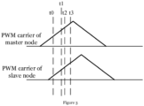
- carrier synchronization The basic idea of carrier synchronization is that a master node (e.g., the master PCS of the ESS) broadcasts its own carrier signal on a bus, meanwhile multiple slave nodes (e.g., the slave PCSs of the ESS) which are connected on the same bus with the master node receive the carrier signal broadcast by the master node, and, using this carrier signal as a reference, the multiple slave nodes adjust their own carrier signals to be consistent with the carrier signal of the master node. As shown in Figure 3 , within a cycle of the carrier synchronization, steps corresponding to four moments to-t3 which are described below may be performed.
- the master node sends a timing signal (e.g., clock synchronization signal) which may be any data.
- a timing signal e.g., clock synchronization signal
- the timing signal is sent successfully, and because the sending delay of CAN communication data is short, the moment when the master node sends the timing signal successfully can be considered as the same moment when the slave nodes receive the timing signal successfully.
- DSP Digital Signal Processor
- the CAN communication module can automatically record the moment of receiving and sending successfully and record the value of the CAN time base counter corresponding to this moment to the MOTSx register.
- the recording of the moments of receiving and sending successfully of the CAN communication needs to be done by software.
- the receiving and sending interrupt of CAN communication can be used to record the moments of receiving and sending successfully, and in order to ensure recording without delay, interrupt nesting is required and the priority of CAN interrupt should be the highest.
- the operations of the flags need to be understood after entering an interrupt.
- the interrupt enable register (IER) and the interrupt global mask bit (INTM) are automatically saved in the stack firstly. Then, the IER and the interrupt flag register (IFR) are automatically cleared, and the INTM is set to 1 to mask the interrupt. After leaving the interrupt, the IER and INTM are automatically recovered from the stack.
- ADC interrupt There are three interrupts in the program of an inverter of a PCS: ADC interrupt, CPUTIMERo interrupt and DCAN interrupt. In order to ensure that DCAN has the highest priority, the other two interrupts must be nested open, and DCAN interrupt is not nested open.
- the interrupt of DCAN is INT 9.5.
- the CAN receiving and sending functions of the interrupt service need to record the moment of receiving and sending successfully.
- the slave nodes receive the PWM_Count_Mt1 sent by the master node.
- the slave nodes calculate the difference between PWM_Count_St1 and PWM_Count_Mt1, and obtain the adjustment amount (+1 or -1) of the PWM cycle register (TBPRD) of the slave nodes according to the sign this difference.
- the at least two PCSs of the ESS communicate with each other through a CAN bus for current sharing and each PCS broadcasts its own current sharing information (positive sequence current, negative sequence current and the like) through the CAN bus.
- each PCS may share its own information through a CAN bus for information sharing to share other information except for the current sharing information.
- control method provided by the present disclosure may further include the following steps:
- a traditional droop control may be adopted. Assuming that the connection impedance between modules is inductive, there is a droop control relationship of P-f (active power-frequency) and Q-U (reactive power-voltage).
- both the second given value of D-axis negative sequence voltage and the second given value of Q-axis negative sequence voltage are zero.
- obtaining the second given value of positive sequence voltage amplitude of the present PCS and the second given value of positive sequence phase of the present PCS based on the second current sharing control loop may include the following steps:
- the preset angular frequency can be pre-set according to actual demand and is not limited in the present disclosure.
- the control method in the VSG parallel off-grid mode is similar to the control method in the AC/DC parallel off-grid mode, except that different current sharing control loops are used to output different given values of positive sequence voltage amplitude, given values of positive sequence phase, given values of D-axis negative sequence voltage and given values of Q-axis negative sequence voltage.
- the DC bus midpoint control loop may determine the second midpoint target control amount of the present PCS according to the relevant parameters of the present PCS, without the need to follow the control amount of the master PCS.
- Other aspects in the VSG parallel off-grid mode can refer to the description of the control method in the AC/DC parallel off-grid mode and will not be repeated.
- control method provided by the present disclosure may further include the following steps:
- both the third given value of D-axis negative sequence voltage and the third given value of Q-axis negative sequence voltage are zero.
- the third given value of positive sequence voltage amplitude may be the preset voltage amplitude mentioned above.
- the preset voltage amplitude may be the second given value of positive sequence voltage amplitude in the VSG parallel off-grid mode when the second droop coefficient n in the second current sharing control loop is zero.
- the third given value of positive sequence phase may be the preset phase value mentioned above.
- the preset phase value may be the second given value of positive sequence phase in the VSG parallel off-grid mode when the first droop coefficient m in the second current sharing control loop is zero.
- the repetitive control loop is added and the zero-sequence current loop is reduced.
- Other aspects in the stand-alone off-grid mode can refer to the description of the control method in the AC/DC parallel off-grid mode and will not be repeated.
- determining the fourth D-axis positive sequence current control amount and the fourth Q-axis positive sequence current control amount based on the repetitive control loop may include the following steps:
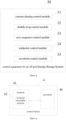
- Figure 4 is a schematic diagram of the structure of the control equipment for an off-grid ESS including at least two PCSs, which, for illustrative purposes, only shows the portions related to embodiments of the present disclosure.
- the control equipment shown in Figure 4 is described in detail below.
- Control equipment 30 for an off-grid ESS shown in Figure 4 includes a current sharing control module 31, a double-loop control module 32, a zero-sequence control module 33, a midpoint control module 34 and a waveform control module 35.
- Current sharing control module 31 is used to, when the ESS is operating in an AC/ DC parallel off-grid mode, obtain a first given value of positive sequence voltage amplitude of a present PCS to be controlled, a first given value of positive sequence phase of the present PCS, a first given value of D-axis negative sequence voltage of the present PCS and a first given value of Q-axis negative sequence voltage of the present PCS based on a first current sharing control loop, where the present PCS is any PCS in operation among the at least two PCSs (i.e., all the PCSs of the ESS), in the AC/DC parallel off-grid mode, the AC sides of all the PCSs of the ESS are connected in parallel and the DC sides of all the PCSs of the ESS are connected in parallel.
- Double-loop control module 32 is used to determine a first D-axis target control amount and a first Q-axis target control amount according to the first given value of positive sequence voltage amplitude, the first given value of positive sequence phase, the first given value of D-axis negative sequence voltage, the first given value of Q-axis negative sequence voltage, an outer voltage loop and an inner current loop.
- Zero-sequence control module 33 is used to determine a first zero-axis target control amount based on a zero-sequence current loop.
- Midpoint control module 34 is used to determine a first midpoint target control amount of a master PCS based on a DC bus midpoint control loop, where the master PCS is a PCS in operation among all the PCSs of the ESS, leaving other PCSs in operation of all the PCSs of the ESS are slave PCSs.
- Waveform control module 35 is used to generate a first target waveform according to the first D-axis target control amount, the first Q-axis target control amount, the first zero-axis target control amount and the first midpoint target control amount, and control the present PCS according to the first target waveform.
- zero-sequence control module 33 is further used to:
- current sharing control module 31 is further used to:
- double-loop control module 32 is further used to:
- the DC bus midpoints of the at least two PCSs are connected to each other.
- control equipment 30 for an off-grid ESS further includes a carrier synchronization module.
- the carrier synchronization module is used to, when the ESS is operating in the AC/DC parallel off-grid mode, perform a carrier synchronization control on the at least two PCSs through a Controller Area Network.
- control equipment 30 further includes a VSG parallel off-grid control module.
- the VSG parallel off-grid control module is used to:
- control equipment 30 further includes a stand-alone off-grid control module.
- the stand-alone off-grid control module is used to:
- FIG. 5 is a schematic diagram of a control device provided by an embodiment of the present disclosure.
- the control device 4 may include a processor 40 and a memory 41.
- Memory 41 is used to store a computer executable program 42.
- Processor 40 is used to invoke and execute program 42 stored in memory 41 to perform the steps in the embodiments of control method for an off-grid ESS, e.g., steps S101 to S105 shown in Figure 2 .
- Processor 40 is used to invoke and execute program 42 stored in memory 41 to implement the functions of the modules in the embodiments of control device, e.g., the functions of modules 31 to 35 shown in Figure 4 .
- program 42 may be divided into one or more modules/units, and the one or more modules/units are stored in memory 41 and executed by processor 40 to implement the present disclosure.
- the one or more modules/units may be a series of computer program instruction segments capable of performing specific functions, and the instruction segments are used to describe the execution process of program 42 in control device 4.
- program 42 may be divided into modules 31 to 35 shown in Figure 4 .
- the control device 4 may include, but is not limited to, processor 40 and memory 41. Those skilled in the art can understand that Figure 5 is only an example of control device 4, and does not constitute limitation to control device 4.
- the control device 4 may include more or less components than shown, some components combined, or different components, for example, the control device 4 may also include input and output devices, network access devices, buses and the like.
- Processor 40 may be Central Processing Units (CPU), other general-purpose processors, Digital Signal Processors (DSP), Application Specific Integrated Circuits (ASIC), Field-Programmable Gate Arrays (FPGA), other programmable logic devices, discrete gates, transistor logic devices, discrete hardware components or the like.
- the general-purpose processors may be microprocessors, any conventional processors or the like.
- Memory 41 may be internal storage units of the control device 4, such as hard disks or memories of the control device 4. Memory 41 may also be external storage devices of electronic device 4, such as plug-in hard disks, Smart Memory Cards (SMC), Secure Digital Cards (SD), flash cards and the like equipped on control device 4. Further, memory 41 may also include both internal storage units and external storage devices of the control device 4. Memory 41 is used to store program 42 and other programs and data required by control device 4. Memory 41 can also be used to temporarily store data that has been output or will be output.
- the present disclosure also provides an ESS.
- the ESS may include at least two PCSs and the control device mentioned above. The at least two PCSs are controlled by the control device.
- the control device is used to, when the ESS is in off-grid state, make the ESS operate in the AC/ DC parallel off-grid mode through controlling the AC sides of the at least two PCSs (all the PCSs of the ESS) to be connected in parallel and the DC sides of all the PCSs of the ESS to be connected in parallel, make the ESS operate in the VSG parallel off-grid mode through controlling the AC sides of all the PCSs of the ESS to be connected in parallel and the DC sides of all the a PCSs of the ESS to be separate from each other, and make the ESS operate in the stand-alone off-grid mode through controlling that only one PCS of all the PCSs of the ESS is in operating(i.e., in an operating state).
- the division of the above-mentioned functional modules is only an example for illustration.
- the above-mentioned function can be completed by different functional units and modules as required, that is, the internal structure of the control device can be divided into different functional units or modules to complete all or part of the functions described above.
- One or more functional modules in the embodiments may be integrated into one processing unit, or each module may exist physically alone, or two or more modules may be integrated into one unit.
- the above-mentioned integrated units may be implemented in the form of hardware or software functional units.
- the specific names of the functional modules are only for the convenience of distinguishing from each other, and are not used to limit the protection scope of the present disclosure.
- For the specific operation process of the modules in the above-mentioned control device and ESS reference may be made to the description of corresponding processes in the foregoing embodiments of control method, which will not be repeated.
- modules and algorithm steps in the embodiments of the present disclosure can be implemented in electronic hardware, or a combination of computer software and electronic hardware. Whether the functions of these modules and algorithm steps are performed in hardware or software depends on the specific application and design constraints of the technical solution. Those skilled in the art may implement the described functions using different methods for each particular application, which should not be considered beyond the scope of the present disclosure.
- control devices and methods may be implemented in other manners.
- the control device in the embodiment described above are merely illustrative.
- the division of the modules is only a logical function division, and there may be other division manners in actual implementations.
- multiple units or components may be combined, or may be integrated into another system, or some features may be omitted or not implemented.
- the shown or discussed mutual coupling, direct coupling or communication connection may be implemented through some interfaces, indirect coupling or communication connection of devices or units, and may be in electrical, mechanical or other forms.
- a component shown as a unit may or may not be a physical unit. It may be located in one place, or it may be distributed over a number of network elements. Some or all of the units may be selected according to actual needs to achieve the purpose of the solution of the embodiments of the present disclosure.
- each functional unit in each embodiment of the present disclosure may be integrated into one processing unit, or each unit may exist physically alone, or two or more units may be integrated into one unit.
- the above-mentioned integrated units may be implemented in the form of hardware or software functional units.
- the integrated modules/units if implemented in the form of software functional units and sold or used as independent products, may be stored in a computer-readable storage medium.
- all or part of the processes in the above embodiments of the control methods of the present disclosure can be implemented by instructing relevant hardware through a computer program.
- the computer program can be stored in a computer-readable storage medium, and when executed by the processor, the computer program can implement the steps in the above-mentioned embodiments of the control method for an off-grid ESS.
- the computer program may include computer program code which may be in the form of source code, object code, executable file, some intermediate form or the like.
- the computer-readable medium may be: any entity or device capable of carrying the computer program code, recording mediums, U disks, removable hard disks, magnetic disks, optical disks, computer memories, Read-Only Memories (ROM), Random Access Memories (RAM), electric carrier signals, telecommunication signals and software distribution mediums or the like. It should be noted that what the computer-readable media can be may be determined according to the requirements of legislation and patent practice in the jurisdiction, for example, in some jurisdictions, according to legislation and patent practice, the computer-readable media cannot be electrical carrier signals and telecommunication signals.
Landscapes
- Engineering & Computer Science (AREA)
- Power Engineering (AREA)
- Inverter Devices (AREA)
- Supply And Distribution Of Alternating Current (AREA)
Applications Claiming Priority (1)
| Application Number | Priority Date | Filing Date | Title |
|---|---|---|---|
| CN202211380798.8A CN115833222A (zh) | 2022-11-04 | 2022-11-04 | 储能系统的离网控制方法、控制设备及储能系统 |
Publications (3)
| Publication Number | Publication Date |
|---|---|
| EP4372945A2 true EP4372945A2 (de) | 2024-05-22 |
| EP4372945A3 EP4372945A3 (de) | 2024-06-26 |
| EP4372945B1 EP4372945B1 (de) | 2026-05-20 |
Family
ID=85526749
Family Applications (1)
| Application Number | Title | Priority Date | Filing Date |
|---|---|---|---|
| EP23207714.9A Active EP4372945B1 (de) | 2022-11-04 | 2023-11-03 | Steuerungsverfahren für ein netzunabhängiges energiespeichersystem, steuerungsvorrichtung und energiespeichersystem |
Country Status (2)
| Country | Link |
|---|---|
| EP (1) | EP4372945B1 (de) |
| CN (1) | CN115833222A (de) |
Families Citing this family (1)
| Publication number | Priority date | Publication date | Assignee | Title |
|---|---|---|---|---|
| CN119813279B (zh) * | 2024-11-29 | 2026-02-06 | 厦门科华数能科技有限公司 | 多机并联储能系统的群黑启动方法、装置及储能系统 |
Family Cites Families (3)
| Publication number | Priority date | Publication date | Assignee | Title |
|---|---|---|---|---|
| US10305286B2 (en) * | 2015-08-14 | 2019-05-28 | Solarcity Corporation | Multiple inverter power control systems in an energy generation system |
| JP6781637B2 (ja) * | 2017-01-27 | 2020-11-04 | 株式会社日立産機システム | 蓄電池と電力変換装置の連携システムの制御方法、およびパワーコンディショニングシステム |
| CN111244933A (zh) * | 2020-03-09 | 2020-06-05 | 台达电子企业管理(上海)有限公司 | 储能装置、电力系统及其控制方法 |
-
2022
- 2022-11-04 CN CN202211380798.8A patent/CN115833222A/zh active Pending
-
2023
- 2023-11-03 EP EP23207714.9A patent/EP4372945B1/de active Active
Also Published As
| Publication number | Publication date |
|---|---|
| EP4372945B1 (de) | 2026-05-20 |
| EP4372945A3 (de) | 2024-06-26 |
| CN115833222A (zh) | 2023-03-21 |
Similar Documents
| Publication | Publication Date | Title |
|---|---|---|
| CN110137984B (zh) | 电池储能系统的相间功率差异化控制电路及方法 | |
| CN107887928A (zh) | 一种储能系统的控制方法和装置 | |
| US11975619B2 (en) | Controllers, devices, and methods for performing power quality control using direct current fast charging devices | |
| CN107733215B (zh) | 一种三电平多模块逆变器均流控制方法及装置 | |
| CN115241904B (zh) | 一种大功率多功能高效充电系统功率补偿控制方法及装置 | |
| US20230067971A1 (en) | Permanent-magnet synchronous machine control method and device, and permanent-magnet synchronous machine control system | |
| CN115037182A (zh) | 一种储能变流器并联环流抑制方法及系统 | |
| CN120855552A (zh) | 自同步电压源组串式光伏逆变器系统及控制方法 | |
| CN115833222A (zh) | 储能系统的离网控制方法、控制设备及储能系统 | |
| Salimbeni et al. | Integration of active filter and energy storage system for power quality improvement in microgrids | |
| US12160165B2 (en) | Power conversion system and communication method thereof | |
| CN118589629A (zh) | 一种级联h桥储能系统全电池单元快速soc均衡控制方法 | |
| Stefanski et al. | A novel high dynamic six phase 120 kW Power Hardware in the Loop Emulation Test Bench for emulating AC/DC Grids and Electrical Machines | |
| de Oliveira et al. | Predictive control on multilevel back-to-back cascade h-bridge driving an induction motor | |
| CN118412903A (zh) | 一种压频等效的类同步发电机变流器及其控制方法 | |
| CN114614484A (zh) | 一种储能型柔性互联协同控制配电系统 | |
| CN110429852A (zh) | 一种抑制逆变器开关环流的方法、系统及终端设备 | |
| Ronghui et al. | Decentralized solution based on small-ac-signal injection for accurate power sharing in islanded microgrids with complex line impedances | |
| Chang et al. | A Voltage-Following Strategy Used in Programmable Electronic Loads with Shared DC Bus | |
| CN119813279B (zh) | 多机并联储能系统的群黑启动方法、装置及储能系统 | |
| CN112886805A (zh) | 并联逆变拓扑控制方法及系统 | |
| CN120566471A (zh) | 一种模块化柔性变压器的分层控制多机并联方法 | |
| CN116001626B (zh) | 一种充电站的控制方法及装置 | |
| CN114374234B (zh) | 一种基于虚拟同步机并联系统的无功均分控制系统和方法 | |
| CN116131349A (zh) | 储能系统的控制方法、pcs及储能系统 |
Legal Events
| Date | Code | Title | Description |
|---|---|---|---|
| PUAI | Public reference made under article 153(3) epc to a published international application that has entered the european phase |
Free format text: ORIGINAL CODE: 0009012 |
|
| STAA | Information on the status of an ep patent application or granted ep patent |
Free format text: STATUS: THE APPLICATION HAS BEEN PUBLISHED |
|
| AK | Designated contracting states |
Kind code of ref document: A2 Designated state(s): AL AT BE BG CH CY CZ DE DK EE ES FI FR GB GR HR HU IE IS IT LI LT LU LV MC ME MK MT NL NO PL PT RO RS SE SI SK SM TR |
|
| PUAL | Search report despatched |
Free format text: ORIGINAL CODE: 0009013 |
|
| AK | Designated contracting states |
Kind code of ref document: A3 Designated state(s): AL AT BE BG CH CY CZ DE DK EE ES FI FR GB GR HR HU IE IS IT LI LT LU LV MC ME MK MT NL NO PL PT RO RS SE SI SK SM TR |
|
| RIC1 | Information provided on ipc code assigned before grant |
Ipc: H02J 3/38 20060101ALI20240523BHEP Ipc: H02J 3/32 20060101AFI20240523BHEP |
|
| STAA | Information on the status of an ep patent application or granted ep patent |
Free format text: STATUS: REQUEST FOR EXAMINATION WAS MADE |
|
| 17P | Request for examination filed |
Effective date: 20241220 |
|
| GRAP | Despatch of communication of intention to grant a patent |
Free format text: ORIGINAL CODE: EPIDOSNIGR1 |
|
| STAA | Information on the status of an ep patent application or granted ep patent |
Free format text: STATUS: GRANT OF PATENT IS INTENDED |
|
| INTG | Intention to grant announced |
Effective date: 20260216 |
|
| GRAS | Grant fee paid |
Free format text: ORIGINAL CODE: EPIDOSNIGR3 |
|
| GRAA | (expected) grant |
Free format text: ORIGINAL CODE: 0009210 |
|
| STAA | Information on the status of an ep patent application or granted ep patent |
Free format text: STATUS: THE PATENT HAS BEEN GRANTED |