EP4372850A1 - Method and apparatus for analyzing fuel cell - Google Patents
Method and apparatus for analyzing fuel cell Download PDFInfo
- Publication number
- EP4372850A1 EP4372850A1 EP22215047.6A EP22215047A EP4372850A1 EP 4372850 A1 EP4372850 A1 EP 4372850A1 EP 22215047 A EP22215047 A EP 22215047A EP 4372850 A1 EP4372850 A1 EP 4372850A1
- Authority
- EP
- European Patent Office
- Prior art keywords
- fuel cell
- electrode
- analyzing
- pore size
- state
- Prior art date
- Legal status (The legal status is an assumption and is not a legal conclusion. Google has not performed a legal analysis and makes no representation as to the accuracy of the status listed.)
- Pending
Links
Images


Classifications
-
- H—ELECTRICITY
- H01—ELECTRIC ELEMENTS
- H01M—PROCESSES OR MEANS, e.g. BATTERIES, FOR THE DIRECT CONVERSION OF CHEMICAL ENERGY INTO ELECTRICAL ENERGY
- H01M8/00—Fuel cells; Manufacture thereof
- H01M8/04—Auxiliary arrangements, e.g. for control of pressure or for circulation of fluids
- H01M8/04298—Processes for controlling fuel cells or fuel cell systems
- H01M8/04313—Processes for controlling fuel cells or fuel cell systems characterised by the detection or assessment of variables; characterised by the detection or assessment of failure or abnormal function
- H01M8/04664—Failure or abnormal function
-
- H—ELECTRICITY
- H01—ELECTRIC ELEMENTS
- H01M—PROCESSES OR MEANS, e.g. BATTERIES, FOR THE DIRECT CONVERSION OF CHEMICAL ENERGY INTO ELECTRICAL ENERGY
- H01M4/00—Electrodes
- H01M4/86—Inert electrodes with catalytic activity, e.g. for fuel cells
- H01M4/8605—Porous electrodes
-
- G—PHYSICS
- G01—MEASURING; TESTING
- G01N—INVESTIGATING OR ANALYSING MATERIALS BY DETERMINING THEIR CHEMICAL OR PHYSICAL PROPERTIES
- G01N15/00—Investigating characteristics of particles; Investigating permeability, pore-volume or surface-area of porous materials
- G01N15/08—Investigating permeability, pore-volume, or surface area of porous materials
- G01N15/088—Investigating volume, surface area, size or distribution of pores; Porosimetry
-
- G—PHYSICS
- G01—MEASURING; TESTING
- G01R—MEASURING ELECTRIC VARIABLES; MEASURING MAGNETIC VARIABLES
- G01R31/00—Arrangements for testing electric properties; Arrangements for locating electric faults; Arrangements for electrical testing characterised by what is being tested not provided for elsewhere
- G01R31/36—Arrangements for testing, measuring or monitoring the electrical condition of accumulators or electric batteries, e.g. capacity or state of charge [SoC]
- G01R31/382—Arrangements for monitoring battery or accumulator variables, e.g. SoC
-
- G—PHYSICS
- G01—MEASURING; TESTING
- G01R—MEASURING ELECTRIC VARIABLES; MEASURING MAGNETIC VARIABLES
- G01R31/00—Arrangements for testing electric properties; Arrangements for locating electric faults; Arrangements for electrical testing characterised by what is being tested not provided for elsewhere
- G01R31/36—Arrangements for testing, measuring or monitoring the electrical condition of accumulators or electric batteries, e.g. capacity or state of charge [SoC]
- G01R31/378—Arrangements for testing, measuring or monitoring the electrical condition of accumulators or electric batteries, e.g. capacity or state of charge [SoC] specially adapted for the type of battery or accumulator
-
- H—ELECTRICITY
- H01—ELECTRIC ELEMENTS
- H01M—PROCESSES OR MEANS, e.g. BATTERIES, FOR THE DIRECT CONVERSION OF CHEMICAL ENERGY INTO ELECTRICAL ENERGY
- H01M4/00—Electrodes
- H01M4/86—Inert electrodes with catalytic activity, e.g. for fuel cells
-
- H—ELECTRICITY
- H01—ELECTRIC ELEMENTS
- H01M—PROCESSES OR MEANS, e.g. BATTERIES, FOR THE DIRECT CONVERSION OF CHEMICAL ENERGY INTO ELECTRICAL ENERGY
- H01M4/00—Electrodes
- H01M4/86—Inert electrodes with catalytic activity, e.g. for fuel cells
- H01M4/88—Processes of manufacture
-
- G—PHYSICS
- G01—MEASURING; TESTING
- G01N—INVESTIGATING OR ANALYSING MATERIALS BY DETERMINING THEIR CHEMICAL OR PHYSICAL PROPERTIES
- G01N15/00—Investigating characteristics of particles; Investigating permeability, pore-volume or surface-area of porous materials
- G01N15/08—Investigating permeability, pore-volume, or surface area of porous materials
- G01N2015/0833—Pore surface area
-
- Y—GENERAL TAGGING OF NEW TECHNOLOGICAL DEVELOPMENTS; GENERAL TAGGING OF CROSS-SECTIONAL TECHNOLOGIES SPANNING OVER SEVERAL SECTIONS OF THE IPC; TECHNICAL SUBJECTS COVERED BY FORMER USPC CROSS-REFERENCE ART COLLECTIONS [XRACs] AND DIGESTS
- Y02—TECHNOLOGIES OR APPLICATIONS FOR MITIGATION OR ADAPTATION AGAINST CLIMATE CHANGE
- Y02E—REDUCTION OF GREENHOUSE GAS [GHG] EMISSIONS, RELATED TO ENERGY GENERATION, TRANSMISSION OR DISTRIBUTION
- Y02E60/00—Enabling technologies; Technologies with a potential or indirect contribution to GHG emissions mitigation
- Y02E60/30—Hydrogen technology
- Y02E60/50—Fuel cells
Definitions
- the present invention relates to a method and apparatus for analyzing a fuel cell, and more particularly, to a degradation verification method and an air electrode pore size measurement method of a fuel cell membrane electrode assembly (MEA).
- MEA fuel cell membrane electrode assembly
- a membrane electrode assembly (MEA) of a fuel cell is divided into an air electrode/polymer electrolyte membrane/hydrogen electrode configuration.
- Hydrogen and air which are used as fuel, flow into the air electrode and the hydrogen electrode through a separator/gas diffusion layer (GDL), respectively.
- GDL separator/gas diffusion layer
- hydrogen is oxidized to generate electrons, and hydrogen ions pass through the polymer electrolyte membrane and react with oxygen to produce electricity and water at the air electrode.
- General components of the air electrode include a catalyst supported on carbon and a binder for maintaining ionic conduction and adhesion of components. Since an oxygen reduction reaction of the air electrode is slower than an oxidation reaction of the hydrogen electrode and water is continuously produced as a reactant, it is important that air used as fuel is uniformly supplied to the inside of an electrode having a microstructure during operation.
- the catalyst and the binder should be manufactured as an electrode after being prepared as a stably dispersed mixture using an appropriate solvent and environmental conditions.
- a method of fuel cell analysis includes measuring a portion of an electrode of a fuel cell to determine a measured result.
- the method also includes analyzing a state of the fuel cell according to the measured result.
- Measuring the portion of the electrode of the fuel cell may include measuring a pore size of the electrode of the fuel cell.
- the method may include forming a portion of the electrode of the fuel cell by at least some of a coating process, a bonding process, and an attaching process.
- Analyzing the state of the fuel cell may include analyzing the state of the fuel cell based on a measured pore size.
- Measuring the portion of the electrode of the fuel cell may further include removing at least one of impurities and moisture located at least one of inside and around the electrode of the fuel cell.
- Measuring the pore size of the electrode of the fuel cell may further include calculating the pore size based on a result of nitrogen supply to the electrode of the fuel cell.
- the apparatus includes an electrode measurer configured to measure at least a portion of an electrode of a fuel cell to determine a measured result, and a fuel cell state analyzer configured to analyze a state of the fuel cell according to the measured result.
- the electrode measurer may be further configured to measure a pore size of the electrode of the fuel cell.
- the electrode measurer may be further configured to measure at least a portion of an air electrode of the fuel cell.
- the portion of the electrode of the fuel cell may be formed by at least some of a coating process, a bonding process, and an attaching process.
- the fuel cell state analyzer may analyze the state of the fuel cell based on the measured pore size.
- the apparatus for analyzing a fuel cell may further include an impurity remover configured to remove at least one of impurities and moisture located at least one of inside and around the electrode of the fuel cell.
- the electrode measurer may be further configured to calculate the pore size based on a result of nitrogen supply to the electrode of the fuel cell.
- first, second, A, B, (a), (b) or the like may be used herein to describe components.
- Each of these terminologies is not used to define an essence, order or sequence of a corresponding component but used merely to distinguish the corresponding component from other component(s).
- a first component may be referred to as a second component, and similarly the second component may also be referred to as the first component.
- FIG. 1 is a flowchart illustrating a method of analyzing a fuel cell according to an embodiment.
- each operation of the method of analyzing a fuel cell may be performed by at least some of components of an apparatus for analyzing a fuel cell, which will be described below.
- the apparatus for analyzing a fuel cell may include at least some of a fuel cell system, a fuel cell analysis device, a fuel cell analyzer, fuel cell analysis instrument, a computing device, an electronic circuit, an electric circuit, and a semiconductor.
- the apparatus for analyzing a fuel cell may remove moisture or impurities inside or around an electrode of a fuel cell.
- At least a portion of an electrode of the fuel cell may be formed by at least some of a coating process, a bonding process, and an attaching process.
- the apparatus for analyzing a fuel cell may measure at least a portion of an electrode of the fuel cell.
- the apparatus for analyzing a fuel cell may measure a pore size of an electrode of the fuel cell.
- the apparatus for analyzing a fuel cell may measure at least a portion of an air electrode of the fuel cell. The apparatus may thereby determine a measured result.
- the apparatus for analyzing a fuel cell may compute/calculate the pore size on the basis of a result of nitrogen supply to an electrode of the fuel cell.
- the apparatus for analyzing a fuel cell may analyze a state of the fuel cell according to the measured result.
- the apparatus for analyzing a fuel cell may analyze the state of the fuel cell on the basis of the measured pore size.
- the apparatus for analyzing a fuel cell may be connected to or include a display/output device.
- the apparatus for analyzing a fuel cell may display or transmit at least a portion of the measured result or the analyzed result to the display.
- the apparatus for analyzing a fuel cell may generate a graph or the like using at least a portion of the measured result or the analyzed result or display/transmit/output the graph to the display/output device.
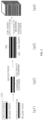
- FIG. 2 is a diagram illustrating an analysis target of the method of analyzing a fuel cell according to an embodiment.
- the fuel cell may include or use at least some of components shown in FIG. 2 . At least some of the components shown in FIG. 2 may be disposed close to each other.
- the fuel cell may include a gas diffusion layer (GDL), a sub gasket, an air electrode, an electrolyte membrane, and a hydrogen electrode as components.
- GDL gas diffusion layer
- a first component among the components of the fuel cell may be disposed on a second component different from the first component.
- an electrode coating of the fuel cell can be seen.
- a membrane electrode assembly which is an electrode of the fuel cell, may undergo a process of coating air/hydrogen electrodes with release papers and bonding the air/hydrogen electrodes to the electrolyte membrane, and then a process of attaching a sub-gasket/GDL for facilitating sealing and fuel supply may be performed. Then, when a separator is positioned between each MEA and then stacking is performed, a fuel cell stack is formed. Durability evaluation of the fuel cell MEA the may be performed after the fuel cell stack is formed.
- the apparatus for analyzing a fuel cell may provide a method of analyzing the pore size of the coated air electrode 201 and predicting degradation of the MEA.
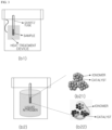
- FIG. 3 is a diagram illustrating processes in the method of analyzing a fuel cell according to an embodiment.
- the apparatus for analyzing a fuel cell may perform two processes that are a pretreatment process and an analysis process in an adsorption/desorption analysis method of used nitrogen.
- the apparatus for analyzing a fuel cell may perform at least some of the pretreatment process and the analysis process.
- a specimen or sample may include at least a portion of the fuel cell.
- the pretreatment process is an operation of removing moisture and impurities in the sample and may be performed at a temperature ranging around 80 to 110 °C for 12 to 24 hours.
- the analysis process is an operation of analyzing a surface area of the sample.
- a pretreated sample is put into a vessel containing liquid nitrogen, nitrogen gas is injected, and then the surface area may be measured by varying an amount of the nitrogen gas adsorbed on a sample surface while varying a relative pressure.
- the apparatus for analyzing a fuel cell may analyze an electrode of the fuel cell (an electrode for the fuel cell).
- the apparatus for analyzing a fuel cell may analyze/use a dispersion state/dispersity of a catalyst or ionomer with respect to an electrode of the fuel cell.
- An electrode may be coated with the catalyst and ionomer after the catalyst and ionomer are dispersed.
- a specific surface area of the catalyst, which is exposed varies according to the dispersion state of the ionomer.
- the ionomer uniformly surrounds the catalyst, otherwise, as shown in b22 of FIG. 3 , the ionomer aggregates and thus the specific surface area of the exposed catalyst is changed.
- a position where hydrogen/oxygen reacts in the fuel cell is a portion in which the catalyst and ionomer are dispersed well.
- an active area is decreased, and when continuous reactions occur in the aggregated portion of the ionomer, hydrogen/oxygen transfer is hindered by generated water so that the generated water may be a cause of long-term degradation.
- the apparatus for analyzing a fuel cell may analyze/calculate the degree of difference in the degree of degradation of the fuel cell according to the dispersity of the ionomer, convert/transform/compute/calculate a specific surface area measured after measuring the specific surface area of the exposed electrode into an average pore size, and provide a new index capable of determining/analyzing the degree of degradation of the fuel cell.
- FIG. 4 is a graph showing a relationship between a measured pore size of an electrode and a degradation increase rate in the method of analyzing a fuel cell according to an embodiment.
- the degradation increase rate decreases as the average pore size increases.
- the apparatus for analyzing a fuel cell may numerically determine/analyze that the degradation increase rate is reduced to 40% or less when the average pore size is 16 nm or more.
- the apparatus for analyzing a fuel cell may predict/determine/derive that durability is improved when the average pore size of the fuel cell is formed to be 16 to 17 nm or more during manufacturing of an electrode layer of the fuel cell.
- the apparatus for analyzing a fuel cell may analyze/determine that the discharge of generated water formed by the electrochemical reaction is suppressed when a size of the pore inside an electrode of the fuel cell is smaller than a (preset/derived) reference size.
- the apparatus for analyzing a fuel cell may predict/determine/analyze that a continuous suppression phenomenon increases a mass transfer resistance phenomenon of the hydrogen and air, which are fuel, eventually reducing fuel cell durability.
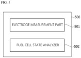
- FIG. 5 is a block diagram illustrating an apparatus for analyzing a fuel cell according to an embodiment.
- an apparatus 500 for analyzing a fuel cell includes an electrode measurement part 501 (for example, electrode measurer) configured to measure at least a portion of an electrode of the fuel cell, and a fuel cell state analyzer 502 configured to analyze a state of the fuel cell according to the measured result.
- electrode measurement part 501 for example, electrode measurer
- fuel cell state analyzer 502 configured to analyze a state of the fuel cell according to the measured result.
- the electrode measurement part 501 may measure a pore size of an electrode of the fuel cell.
- the electrode measurement part 501 may measure at least a portion of an air electrode of the fuel cell.
- At least a portion of an electrode of the fuel cell may be formed by at least some of a coating process, a bonding process, and an attaching process.
- the electrode measurement part 501 may calculate the pore size on the basis of a result of nitrogen supply to an electrode of the fuel cell.
- a fuel cell state analyzer may analyze a state of the fuel cell on the basis of the measured pore size.
- the apparatus 500 for analyzing a fuel cell may further include an impurity removal part (for example, impurity remover) (not shown) configured to remove moisture or impurities inside or around an electrode of the fuel cell.
- an impurity removal part for example, impurity remover
- the apparatus 500 for analyzing a fuel cell may provide an analysis method of pre-verifying degradation of the fuel cell through analysis of the pore size of an electrode.
- the apparatus 500 for analyzing a fuel cell may measure the pore size of an electrode using a nitrogen adsorption and desorption method as an analysis method and has an effect of pre-verifying degradation of an MEA of the fuel cell without a long-term evaluation process.
- the apparatus 500 for analyzing a fuel cell may predict the degree of degradation by analyzing an electrode which is a pre-transfer product, thereby reducing costs used for transfer/bonding/stacking.
- the apparatus 500 for analyzing a fuel cell may be a general-purpose apparatus for measuring a specific surface area of a solid material using a nitrogen adsorption and desorption method and provide a safe method which is convenient to use using only liquid nitrogen and nitrogen without using harmful materials.
- ⁇ part refers to software or hardware components such as a field programmable gate array (FPGA) or an application specific integrated circuit (ASIC) and performs predetermined roles.
- FPGA field programmable gate array
- ASIC application specific integrated circuit
- the term “ ⁇ part” is not limited to software or hardware.
- the “ ⁇ part” may be formed to be stored in an addressable storage medium or to reproduce one or more processors.
- the " ⁇ part” includes components such as software components, object-oriented software components, class components, and task components, and processes, functions, attributes, procedures, sub-routines, segments of program code, drivers, firmware, microcode, circuits, data, databases, data structures, tables, arrays, and variables.
- components and the " ⁇ part” may be combined into a smaller number of components and “ ⁇ parts” or may be further divided into additional components and “ ⁇ parts.”
- the components and the “ ⁇ parts” may be implemented to reproduce one or more central processing units (CPUs) in a device or a secure multimedia card.
- CPUs central processing units
- various embodiments of the present disclosure may be implemented with hardware, firmware, software, or a combination thereof.
- various embodiments of the present disclosure may be implemented with one or more application specific integrated circuits (ASICs), digital signal processors (DSPs), digital signal processing devices (DSPDs), programmable logic devices (PLDs), field programmable gate arrays (FPGAs), general processors, controllers, microcontrollers, or microprocessors.
- ASICs application specific integrated circuits
- DSPs digital signal processors
- DSPDs digital signal processing devices
- PLDs programmable logic devices
- FPGAs field programmable gate arrays
- general processors controllers, microcontrollers, or microprocessors.
- the scope of the present disclosure may include software or machine-executable instructions (for example, an operation system (OS), applications, firmware, programs, etc.), which enable operations of a method according to various embodiments to be executed in a device or a computer, and a non-transitory computer-readable medium capable of being executed in a device or a computer each storing the software or the instructions.
- OS operation system
- applications firmware, programs, etc.
- non-transitory computer-readable medium capable of being executed in a device or a computer each storing the software or the instructions.
Landscapes
- Chemical & Material Sciences (AREA)
- Chemical Kinetics & Catalysis (AREA)
- Electrochemistry (AREA)
- General Chemical & Material Sciences (AREA)
- General Physics & Mathematics (AREA)
- Physics & Mathematics (AREA)
- Life Sciences & Earth Sciences (AREA)
- Manufacturing & Machinery (AREA)
- Engineering & Computer Science (AREA)
- Health & Medical Sciences (AREA)
- Analytical Chemistry (AREA)
- Biochemistry (AREA)
- General Health & Medical Sciences (AREA)
- Immunology (AREA)
- Pathology (AREA)
- Dispersion Chemistry (AREA)
- Sustainable Development (AREA)
- Sustainable Energy (AREA)
- Fuel Cell (AREA)
- Inert Electrodes (AREA)
Abstract
Description
- This application claims the benefit under 35 use 9 119(a) of
Korean Patent Application No. 10-2022-0156567, filed November 21, 2022 - The present invention relates to a method and apparatus for analyzing a fuel cell, and more particularly, to a degradation verification method and an air electrode pore size measurement method of a fuel cell membrane electrode assembly (MEA).
- A membrane electrode assembly (MEA) of a fuel cell is divided into an air electrode/polymer electrolyte membrane/hydrogen electrode configuration. Hydrogen and air, which are used as fuel, flow into the air electrode and the hydrogen electrode through a separator/gas diffusion layer (GDL), respectively. At each electrode, hydrogen is oxidized to generate electrons, and hydrogen ions pass through the polymer electrolyte membrane and react with oxygen to produce electricity and water at the air electrode.
- General components of the air electrode include a catalyst supported on carbon and a binder for maintaining ionic conduction and adhesion of components. Since an oxygen reduction reaction of the air electrode is slower than an oxidation reaction of the hydrogen electrode and water is continuously produced as a reactant, it is important that air used as fuel is uniformly supplied to the inside of an electrode having a microstructure during operation.
- In addition, since an electrochemical reaction in which oxygen is reduced mainly occurs at a three-phase interface where three different phases of carbon/catalyst/binder are in contact with each other, it is also important to design an electrode layer using an appropriate dispersion method for a slurry compound. Therefore, the catalyst and the binder should be manufactured as an electrode after being prepared as a stably dispersed mixture using an appropriate solvent and environmental conditions.
- This Summary is provided to introduce a selection of concepts in a simplified form that are further described below in the Detailed Description. This Summary is not intended to identify key features or essential features of the claimed subject matter, nor is it intended to be used as an aid in determining the scope of the claimed subject matter.
- In one general aspect, here is provided a method of fuel cell analysis. The method includes measuring a portion of an electrode of a fuel cell to determine a measured result. The method also includes analyzing a state of the fuel cell according to the measured result.
- Measuring the portion of the electrode of the fuel cell may include measuring a pore size of the electrode of the fuel cell.
- The method may include forming a portion of the electrode of the fuel cell by at least some of a coating process, a bonding process, and an attaching process.
- Analyzing the state of the fuel cell may include analyzing the state of the fuel cell based on a measured pore size.
- Measuring the portion of the electrode of the fuel cell may further include removing at least one of impurities and moisture located at least one of inside and around the electrode of the fuel cell.
- Measuring the pore size of the electrode of the fuel cell may further include calculating the pore size based on a result of nitrogen supply to the electrode of the fuel cell.
- In another general aspect, here is provided for fuel cell analysis. The apparatus includes an electrode measurer configured to measure at least a portion of an electrode of a fuel cell to determine a measured result, and a fuel cell state analyzer configured to analyze a state of the fuel cell according to the measured result.
- The electrode measurer may be further configured to measure a pore size of the electrode of the fuel cell.
- The electrode measurer may be further configured to measure at least a portion of an air electrode of the fuel cell.
- The portion of the electrode of the fuel cell may be formed by at least some of a coating process, a bonding process, and an attaching process.
- The fuel cell state analyzer may analyze the state of the fuel cell based on the measured pore size.
- The apparatus for analyzing a fuel cell may further include an impurity remover configured to remove at least one of impurities and moisture located at least one of inside and around the electrode of the fuel cell.
- The electrode measurer may be further configured to calculate the pore size based on a result of nitrogen supply to the electrode of the fuel cell.
- Other features and aspects will be apparent from the following detailed description, the drawings, and the claims.
-
-
FIG. 1 is a flowchart illustrating a method of analyzing a fuel cell according to an embodiment. -
FIG. 2 is a diagram illustrating an analysis target of the method of analyzing a fuel cell according to an embodiment. -
FIG. 3 is a diagram illustrating processes in the method of analyzing a fuel cell according to an embodiment. -
FIG. 4 is a graph showing a relationship between a measured pore size of an electrode and a degradation increase rate in the method of analyzing a fuel cell according to an embodiment. -
FIG. 5 is a block diagram illustrating an apparatus for analyzing a fuel cell according to an embodiment. - Throughout the drawings and the detailed description, unless otherwise described or provided, the same drawing reference numerals will be understood to refer to the same elements, features, and structures. The drawings may not be to scale, and the relative size, proportions, and depiction of elements in the drawings may be exaggerated for clarity, illustration, and convenience.
- The following detailed description is provided to assist the reader in gaining a comprehensive understanding of the methods, apparatuses, and/or systems described herein. However, various changes, modifications, and equivalents of the methods, apparatuses, and/or systems described herein will be apparent after an understanding of the disclosure of this application. For example, the sequences of operations described herein are merely examples, and are not limited to those set forth herein, but may be changed as will be apparent after an understanding of the disclosure of this application, with the exception of operations necessarily occurring in a certain order.
- The features described herein may be embodied in different forms and are not to be construed as being limited to the examples described herein. Rather, the examples described herein have been provided merely to illustrate some of the many possible ways of implementing the methods, apparatuses, and/or systems described herein that will be apparent after an understanding of the disclosure of this application.
- Advantages and features of the present disclosure and methods of achieving the advantages and features will be clear with reference to embodiments described in detail below together with the accompanying drawings. However, the present disclosure is not limited to the embodiments disclosed herein but will be implemented in various forms. The embodiments of the present disclosure are provided so that the present disclosure is adequately disclosed, and a person with ordinary skill in the art can fully understand the scope of the present disclosure. Meanwhile, the terms used in the present specification are for explaining the embodiments, not for limiting the present disclosure.
- Terms, such as first, second, A, B, (a), (b) or the like, may be used herein to describe components. Each of these terminologies is not used to define an essence, order or sequence of a corresponding component but used merely to distinguish the corresponding component from other component(s). For example, a first component may be referred to as a second component, and similarly the second component may also be referred to as the first component.
- Throughout the specification, when a component is described as being "connected to," or "coupled to" another component, it may be directly "connected to," or "coupled to" the other component, or there may be one or more other components intervening therebetween. In contrast, when an element is described as being "directly connected to," or "directly coupled to" another element, there can be no other elements intervening therebetween.
- The singular forms "a", "an", and "the" are intended to include the plural forms as well, unless the context clearly indicates otherwise. It will be further understood that the terms "comprises/comprising" and/or "includes/including" when used herein, specify the presence of stated features, integers, steps, operations, elements, and/or components, but do not preclude the presence or addition of one or more other features, integers, steps, operations, elements, components and/or groups thereof.
- Hereinafter, embodiments of the present invention will be described in detail with reference to the accompanying drawings, the same reference numerals are given to the same or corresponding components regardless of the drawing number, and duplicate descriptions thereof will be omitted herein.
-
FIG. 1 is a flowchart illustrating a method of analyzing a fuel cell according to an embodiment. - According to an embodiment, each operation of the method of analyzing a fuel cell may be performed by at least some of components of an apparatus for analyzing a fuel cell, which will be described below.
- The apparatus for analyzing a fuel cell may include at least some of a fuel cell system, a fuel cell analysis device, a fuel cell analyzer, fuel cell analysis instrument, a computing device, an electronic circuit, an electric circuit, and a semiconductor.
- According to an embodiment, the apparatus for analyzing a fuel cell may remove moisture or impurities inside or around an electrode of a fuel cell.
- According to an embodiment, at least a portion of an electrode of the fuel cell may be formed by at least some of a coating process, a bonding process, and an attaching process.
- In
operation 101, the apparatus for analyzing a fuel cell may measure at least a portion of an electrode of the fuel cell. - According to an embodiment, the apparatus for analyzing a fuel cell may measure a pore size of an electrode of the fuel cell.
- According to an embodiment, the apparatus for analyzing a fuel cell may measure at least a portion of an air electrode of the fuel cell. The apparatus may thereby determine a measured result.
- According to an embodiment, the apparatus for analyzing a fuel cell may compute/calculate the pore size on the basis of a result of nitrogen supply to an electrode of the fuel cell.
- In
operation 102, the apparatus for analyzing a fuel cell may analyze a state of the fuel cell according to the measured result. - According to an embodiment, the apparatus for analyzing a fuel cell may analyze the state of the fuel cell on the basis of the measured pore size.
- The apparatus for analyzing a fuel cell may be connected to or include a display/output device. The apparatus for analyzing a fuel cell may display or transmit at least a portion of the measured result or the analyzed result to the display. In addition, the apparatus for analyzing a fuel cell may generate a graph or the like using at least a portion of the measured result or the analyzed result or display/transmit/output the graph to the display/output device.
-
FIG. 2 is a diagram illustrating an analysis target of the method of analyzing a fuel cell according to an embodiment. - The fuel cell may include or use at least some of components shown in
FIG. 2 . At least some of the components shown inFIG. 2 may be disposed close to each other. The fuel cell may include a gas diffusion layer (GDL), a sub gasket, an air electrode, an electrolyte membrane, and a hydrogen electrode as components. A first component among the components of the fuel cell may be disposed on a second component different from the first component. - Referring to a1 of
FIG. 2 , an electrode coating of the fuel cell can be seen. - Referring to a2 of
FIG. 2 , the bonding between the electrodes and the electrolyte membrane of the fuel cell can be seen. - Referring to a3 of
FIG. 2 , the sub-gasket/GDL attachment of the fuel cell can be seen. - Referring to a4 of
FIG. 2 , a stack/stacking of the fuel cell can be seen. - A membrane electrode assembly (MEA), which is an electrode of the fuel cell, may undergo a process of coating air/hydrogen electrodes with release papers and bonding the air/hydrogen electrodes to the electrolyte membrane, and then a process of attaching a sub-gasket/GDL for facilitating sealing and fuel supply may be performed. Then, when a separator is positioned between each MEA and then stacking is performed, a fuel cell stack is formed. Durability evaluation of the fuel cell MEA the may be performed after the fuel cell stack is formed.
- The apparatus for analyzing a fuel cell may provide a method of analyzing the pore size of the
coated air electrode 201 and predicting degradation of the MEA. -
FIG. 3 is a diagram illustrating processes in the method of analyzing a fuel cell according to an embodiment. - The apparatus for analyzing a fuel cell may perform two processes that are a pretreatment process and an analysis process in an adsorption/desorption analysis method of used nitrogen. The apparatus for analyzing a fuel cell may perform at least some of the pretreatment process and the analysis process.
- A specimen or sample may include at least a portion of the fuel cell.
- Referring to b1 of
FIG. 3 , a pretreatment process of the apparatus for analyzing a fuel cell can be seen. - The pretreatment process is an operation of removing moisture and impurities in the sample and may be performed at a temperature ranging around 80 to 110 °C for 12 to 24 hours.
- Referring to b2 of
FIG. 3 , an analysis process of the apparatus for analyzing a fuel cell can be seen. - The analysis process is an operation of analyzing a surface area of the sample. In the analysis process, a pretreated sample is put into a vessel containing liquid nitrogen, nitrogen gas is injected, and then the surface area may be measured by varying an amount of the nitrogen gas adsorbed on a sample surface while varying a relative pressure.
- The apparatus for analyzing a fuel cell may analyze an electrode of the fuel cell (an electrode for the fuel cell). The apparatus for analyzing a fuel cell may analyze/use a dispersion state/dispersity of a catalyst or ionomer with respect to an electrode of the fuel cell.
- An electrode may be coated with the catalyst and ionomer after the catalyst and ionomer are dispersed. In this case, a specific surface area of the catalyst, which is exposed, varies according to the dispersion state of the ionomer. In the case of being dispersed well, as the sample shown in b21 of
FIG. 3 , the ionomer uniformly surrounds the catalyst, otherwise, as shown in b22 ofFIG. 3 , the ionomer aggregates and thus the specific surface area of the exposed catalyst is changed. - A position where hydrogen/oxygen reacts in the fuel cell is a portion in which the catalyst and ionomer are dispersed well. However, as shown in b22 of
FIG. 3 , when the dispersity of the ionomer is low and thus an aggregated portion of the ionomer occurs, an active area is decreased, and when continuous reactions occur in the aggregated portion of the ionomer, hydrogen/oxygen transfer is hindered by generated water so that the generated water may be a cause of long-term degradation. - The apparatus for analyzing a fuel cell may analyze/calculate the degree of difference in the degree of degradation of the fuel cell according to the dispersity of the ionomer, convert/transform/compute/calculate a specific surface area measured after measuring the specific surface area of the exposed electrode into an average pore size, and provide a new index capable of determining/analyzing the degree of degradation of the fuel cell.
-
FIG. 4 is a graph showing a relationship between a measured pore size of an electrode and a degradation increase rate in the method of analyzing a fuel cell according to an embodiment. - Referring to
FIG. 4 , with reference to a relationship between the degradation increase rate and the pore size of an electrode measured by the nitrogen adsorption method, it can be seen that the degradation increase rate decreases as the average pore size increases. - The apparatus for analyzing a fuel cell may numerically determine/analyze that the degradation increase rate is reduced to 40% or less when the average pore size is 16 nm or more.
- The apparatus for analyzing a fuel cell may predict/determine/derive that durability is improved when the average pore size of the fuel cell is formed to be 16 to 17 nm or more during manufacturing of an electrode layer of the fuel cell.
- Through the above analysis result, the apparatus for analyzing a fuel cell may analyze/determine that the discharge of generated water formed by the electrochemical reaction is suppressed when a size of the pore inside an electrode of the fuel cell is smaller than a (preset/derived) reference size.
- The apparatus for analyzing a fuel cell may predict/determine/analyze that a continuous suppression phenomenon increases a mass transfer resistance phenomenon of the hydrogen and air, which are fuel, eventually reducing fuel cell durability.
-
FIG. 5 is a block diagram illustrating an apparatus for analyzing a fuel cell according to an embodiment. - According to an embodiment, an
apparatus 500 for analyzing a fuel cell includes an electrode measurement part 501 (for example, electrode measurer) configured to measure at least a portion of an electrode of the fuel cell, and a fuelcell state analyzer 502 configured to analyze a state of the fuel cell according to the measured result. - According to an embodiment, the
electrode measurement part 501 may measure a pore size of an electrode of the fuel cell. - According to an embodiment, the
electrode measurement part 501 may measure at least a portion of an air electrode of the fuel cell. - According to an embodiment, at least a portion of an electrode of the fuel cell may be formed by at least some of a coating process, a bonding process, and an attaching process.
- According to an embodiment, the
electrode measurement part 501 may calculate the pore size on the basis of a result of nitrogen supply to an electrode of the fuel cell. - According to an embodiment, a fuel cell state analyzer may analyze a state of the fuel cell on the basis of the measured pore size.
- According to an embodiment, the
apparatus 500 for analyzing a fuel cell may further include an impurity removal part (for example, impurity remover) (not shown) configured to remove moisture or impurities inside or around an electrode of the fuel cell. - The
apparatus 500 for analyzing a fuel cell may provide an analysis method of pre-verifying degradation of the fuel cell through analysis of the pore size of an electrode. - The
apparatus 500 for analyzing a fuel cell may measure the pore size of an electrode using a nitrogen adsorption and desorption method as an analysis method and has an effect of pre-verifying degradation of an MEA of the fuel cell without a long-term evaluation process. - In order to evaluate durability of the MEA of the fuel cell, an evaluation process should be performed after transfer/bonding/stacking. However, the
apparatus 500 for analyzing a fuel cell may predict the degree of degradation by analyzing an electrode which is a pre-transfer product, thereby reducing costs used for transfer/bonding/stacking. - The
apparatus 500 for analyzing a fuel cell may be a general-purpose apparatus for measuring a specific surface area of a solid material using a nitrogen adsorption and desorption method and provide a safe method which is convenient to use using only liquid nitrogen and nitrogen without using harmful materials. - The term "~ part" used in the embodiments refers to software or hardware components such as a field programmable gate array (FPGA) or an application specific integrated circuit (ASIC) and performs predetermined roles. However, the term "~ part" is not limited to software or hardware. The "~ part" may be formed to be stored in an addressable storage medium or to reproduce one or more processors. Thus, as an example, the "~ part" includes components such as software components, object-oriented software components, class components, and task components, and processes, functions, attributes, procedures, sub-routines, segments of program code, drivers, firmware, microcode, circuits, data, databases, data structures, tables, arrays, and variables. The functions provided in the components and the "~ part" may be combined into a smaller number of components and "~ parts" or may be further divided into additional components and "~ parts." In addition, the components and the "~ parts" may be implemented to reproduce one or more central processing units (CPUs) in a device or a secure multimedia card.
- Various embodiments of the present disclosure do not list all available combinations but are for describing a representative aspect of the present disclosure, and descriptions of various embodiments may be applied independently or may be applied through a combination of two or more.
- Moreover, various embodiments of the present disclosure may be implemented with hardware, firmware, software, or a combination thereof. In a case where various embodiments of the present disclosure are implemented with hardware, various embodiments of the present disclosure may be implemented with one or more application specific integrated circuits (ASICs), digital signal processors (DSPs), digital signal processing devices (DSPDs), programmable logic devices (PLDs), field programmable gate arrays (FPGAs), general processors, controllers, microcontrollers, or microprocessors.
- The scope of the present disclosure may include software or machine-executable instructions (for example, an operation system (OS), applications, firmware, programs, etc.), which enable operations of a method according to various embodiments to be executed in a device or a computer, and a non-transitory computer-readable medium capable of being executed in a device or a computer each storing the software or the instructions.
- A number of embodiments have been described above. Nevertheless, it will be understood that various modifications may be made. For example, suitable results may be achieved if the described techniques are performed in a different order and/or if components in a described system, architecture, device, or circuit are combined in a different manner and/or replaced or supplemented by other components or their equivalents. Accordingly, other implementations are within the scope of the following claims.
- While this disclosure includes specific examples, it will be apparent after an understanding of the disclosure of this application that various changes in form and details may be made in these examples without departing from the spirit and scope of the claims and their equivalents. The examples described herein are to be considered in a descriptive sense only, and not for purposes of limitation. Descriptions of features or aspects in each example are to be considered as being applicable to similar features or aspects in other examples. Suitable results may be achieved if the described techniques are performed in a different order, and/or if components in a described system, architecture, device, or circuit are combined in a different manner, and/or replaced or supplemented by other components or their equivalents. Therefore, the scope of the disclosure is defined not by the detailed description, but by the claims and their equivalents, and all variations within the scope of the claims and their equivalents are to be construed as being included in the disclosure.
Claims (14)
- A method of fuel cell analysis, the method comprising:measuring at least a portion of an electrode of a fuel cell to determine a measured result; andanalyzing a state of the fuel cell according to the measured result.
- The method of claim 1, wherein measuring the at least the portion of the electrode of the fuel cell includes measuring a pore size of the electrode of the fuel cell.
- The method of claim 1 or 2, wherein measuring the at least the portion of the electrode of the fuel cell includes measuring at least a portion of an air electrode of the fuel cell.
- The method of any one of claims 1 to 3, further comprising:
forming at least a portion of the electrode of the fuel cell by at least some of a coating process, a bonding process, and an attaching process. - The method of any one of claims 2 to 4, wherein analyzing the state of the fuel cell includes analyzing the state of the fuel cell based on a measured pore size.
- The method of any one of claims 1 to 5, wherein measuring the at least the portion of the electrode of the fuel cell further includes removing at least one of impurities and moisture located at least one of inside and around the electrode of the fuel cell.
- The method of any one of claims 2 to 6, wherein measuring the pore size of the electrode of the fuel cell further includes calculating the pore size based on a result of nitrogen supply to the electrode of the fuel cell.
- An apparatus for fuel cell analysis, the apparatus comprising:an electrode measurer configured to measure at least a portion of an electrode of a fuel cell to determine a measured result; anda fuel cell state analyzer configured to analyze a state of the fuel cell according to the measured result.
- The apparatus of claim 8, wherein the electrode measurer is further configured to measure a pore size of the electrode of the fuel cell.
- The apparatus of claim 8 or 9, wherein the electrode measurer is further configured to measure at least a portion of an air electrode of the fuel cell.
- The apparatus of any one of claims 8 to 10, wherein the at least a portion of the electrode of the fuel cell is formed by at least some of a coating process, a bonding process, and an attaching process.
- The apparatus of any one of claims 9 to 11, wherein the fuel cell state analyzer is further configured to analyze the state of the fuel cell based on the measured pore size.
- The apparatus of any one of claims 8 to 12, further comprising an impurity remover configured to remove at least one of impurities and moisture located at least one of inside and around the electrode of the fuel cell.
- The apparatus of any one of claims 9 to 13, wherein the electrode measurer is further configured to calculate the pore size based on a result of nitrogen supply to the electrode of the fuel cell.
Applications Claiming Priority (1)
| Application Number | Priority Date | Filing Date | Title |
|---|---|---|---|
| KR1020220156567A KR102778283B1 (en) | 2022-11-21 | 2022-11-21 | Method and apparatus for analysis of fuel cell |
Publications (1)
| Publication Number | Publication Date |
|---|---|
| EP4372850A1 true EP4372850A1 (en) | 2024-05-22 |
Family
ID=84547195
Family Applications (1)
| Application Number | Title | Priority Date | Filing Date |
|---|---|---|---|
| EP22215047.6A Pending EP4372850A1 (en) | 2022-11-21 | 2022-12-20 | Method and apparatus for analyzing fuel cell |
Country Status (5)
| Country | Link |
|---|---|
| US (1) | US20240170698A1 (en) |
| EP (1) | EP4372850A1 (en) |
| JP (1) | JP2024074739A (en) |
| KR (1) | KR102778283B1 (en) |
| CN (1) | CN118057194A (en) |
Citations (2)
| Publication number | Priority date | Publication date | Assignee | Title |
|---|---|---|---|---|
| JP2011096460A (en) * | 2009-10-28 | 2011-05-12 | Toshiba Corp | Cathode electrode for fuel cell and fuel cell |
| CN103647093B (en) * | 2013-11-26 | 2016-02-10 | 中国华能集团清洁能源技术研究院有限公司 | A kind of performance diagnogtics method of molten carbonate fuel cell |
Family Cites Families (12)
| Publication number | Priority date | Publication date | Assignee | Title |
|---|---|---|---|---|
| KR100303609B1 (en) * | 1998-04-24 | 2001-11-02 | 박호군 | Methods for Preparing LiCoO2-Coated NiO Cathodes for Molten Carbonate Fuel Cell |
| CN100377404C (en) * | 2000-11-16 | 2008-03-26 | 三菱综合材料株式会社 | Solid electrolyte fuel cell and air electrode current collector used therefor |
| JP2009016056A (en) * | 2007-06-29 | 2009-01-22 | Nissan Motor Co Ltd | Fuel cell control system and method |
| KR101098035B1 (en) * | 2009-04-27 | 2011-12-22 | 연세대학교 산학협력단 | Cathode for solic oxide fuel cell |
| KR20120089179A (en) * | 2011-02-01 | 2012-08-09 | 삼성전자주식회사 | Electrode for fuel cell, and membrane electrode assembly and fuel cell including the same |
| KR102025440B1 (en) * | 2012-05-31 | 2019-09-25 | 서울대학교산학협력단 | Methods of fabricating mesoporous composite powder and solid oxide fuel cell using the same |
| KR101807781B1 (en) * | 2013-12-26 | 2017-12-12 | 재단법인 포항산업과학연구원 | Cathod current collectorc and sofc comprising the same |
| KR102112381B1 (en) * | 2016-01-04 | 2020-05-19 | 주식회사 엘지화학 | Apparatus and method for evaluating polymer electrolyte membrane |
| KR101886522B1 (en) * | 2016-11-07 | 2018-08-07 | 현대자동차주식회사 | Control device and method for starting of fuel cell system |
| KR102291279B1 (en) * | 2019-11-29 | 2021-08-23 | 한국생산기술연구원 | MCFC cathode to reduce nickel melt |
| CN113207317A (en) * | 2019-12-12 | 2021-08-03 | 松下知识产权经营株式会社 | Electrode catalyst for fuel cell, electrode catalyst layer for fuel cell, membrane electrode assembly, and fuel cell |
| KR102300201B1 (en) * | 2021-02-19 | 2021-09-08 | 한밭대학교 산학협력단 | Porosity measurement method of porous electrode using electrical conductivity |
-
2022
- 2022-11-21 KR KR1020220156567A patent/KR102778283B1/en active Active
- 2022-12-20 EP EP22215047.6A patent/EP4372850A1/en active Pending
- 2022-12-20 US US18/084,743 patent/US20240170698A1/en not_active Abandoned
- 2022-12-21 JP JP2022204834A patent/JP2024074739A/en active Pending
- 2022-12-29 CN CN202211703458.4A patent/CN118057194A/en active Pending
Patent Citations (2)
| Publication number | Priority date | Publication date | Assignee | Title |
|---|---|---|---|---|
| JP2011096460A (en) * | 2009-10-28 | 2011-05-12 | Toshiba Corp | Cathode electrode for fuel cell and fuel cell |
| CN103647093B (en) * | 2013-11-26 | 2016-02-10 | 中国华能集团清洁能源技术研究院有限公司 | A kind of performance diagnogtics method of molten carbonate fuel cell |
Non-Patent Citations (1)
| Title |
|---|
| YUAN XIAO-ZI ET AL: "A review of functions, attributes, properties and measurements for the quality control of proton exchange membrane fuel cell components", JOURNAL OF POWER SOURCES, vol. 491, 1 April 2021 (2021-04-01), AMSTERDAM, NL, pages 229540, XP093122304, ISSN: 0378-7753, DOI: 10.1016/j.jpowsour.2021.229540 * |
Also Published As
| Publication number | Publication date |
|---|---|
| KR102778283B1 (en) | 2025-03-11 |
| CN118057194A (en) | 2024-05-21 |
| US20240170698A1 (en) | 2024-05-23 |
| KR20240074461A (en) | 2024-05-28 |
| JP2024074739A (en) | 2024-05-31 |
Similar Documents
| Publication | Publication Date | Title |
|---|---|---|
| Hu et al. | Application of electrochemical impedance spectroscopy to degradation and aging research of lithium-ion batteries | |
| Heinzmann et al. | Advanced impedance study of polymer electrolyte membrane single cells by means of distribution of relaxation times | |
| Liu et al. | Influence of operating conditions on the degradation mechanism in high-temperature polymer electrolyte fuel cells | |
| US20140239962A1 (en) | Fuel cell inspection method and inspection device | |
| CA2978528C (en) | Fuel cell internal state detection system and state detection method | |
| Lochner et al. | Local degradation effects in automotive size membrane electrode assemblies under realistic operating conditions | |
| WO2020135693A1 (en) | Method for diagnosing decline of fuel cell stack, method for multi-point analysis of fuel cell, and method for estimating performance of membrane electrode of fuel cell | |
| US10109044B2 (en) | Apparatus for measuring micro-cracks in a membrane electrode assembly and method for predicting generation of micro-cracks in the same | |
| Cruz-Manzo et al. | Inductive effect on the fuel cell cathode impedance spectrum at high frequencies | |
| CN105699902B (en) | Impedance measuring instrument and its method for fuel cell diagnosis | |
| CN114361535A (en) | A method for evaluating hydrogen permeability of fuel cells based on electrochemical impedance spectroscopy | |
| US20070275287A1 (en) | Active test fuel cell for characterizing and qualifying cell-internal fuel cell components | |
| CN116090184A (en) | Method for rapidly calculating acceleration factor of fuel cell membrane electrode under actual vehicle condition | |
| Schonvogel et al. | Effect of air contamination by sulfur dioxide on the high temperature PEM fuel cell | |
| CN113782786B (en) | In-situ detection method and device for hydrogen permeation current of fuel cell stack | |
| CN114373967A (en) | A fuel cell stack hydrogen permeation measurement method | |
| Han et al. | Effect of anode humidity on the performance and current density distribution of PEM fuel cells via experimental and numerical approach | |
| US20240170698A1 (en) | Method and apparatus for analyzing fuel cell | |
| Piela et al. | Looking inside polymer electrolyte membrane fuel cell stack using tailored electrochemical methods | |
| CN114709454A (en) | Fuel cell short-circuit resistance measurement method based on electrochemical impedance spectrum | |
| Yuan et al. | Review on resistance based water content monitoring in vehicle fuel cell stack | |
| Raab et al. | Impedance-based analysis of PEMFC degradation phenomena during accelerated stress tests | |
| CN116247251A (en) | A control method, device, controller and storage medium for a fuel cell system | |
| JP5104677B2 (en) | Fuel cell diagnostic apparatus and diagnostic method | |
| Gunji et al. | Quick crossover current measurement of a polymer electrolyte fuel cell stack with and without cell voltage terminals |
Legal Events
| Date | Code | Title | Description |
|---|---|---|---|
| PUAI | Public reference made under article 153(3) epc to a published international application that has entered the european phase |
Free format text: ORIGINAL CODE: 0009012 |
|
| STAA | Information on the status of an ep patent application or granted ep patent |
Free format text: STATUS: REQUEST FOR EXAMINATION WAS MADE |
|
| 17P | Request for examination filed |
Effective date: 20221220 |
|
| AK | Designated contracting states |
Kind code of ref document: A1 Designated state(s): AL AT BE BG CH CY CZ DE DK EE ES FI FR GB GR HR HU IE IS IT LI LT LU LV MC ME MK MT NL NO PL PT RO RS SE SI SK SM TR |
|
| RAP1 | Party data changed (applicant data changed or rights of an application transferred) |
Owner name: KIA CORPORATION Owner name: HYUNDAI MOTOR COMPANY |
|
| RAP3 | Party data changed (applicant data changed or rights of an application transferred) |
Owner name: KIA CORPORATION Owner name: HYUNDAI MOTOR COMPANY |
|
| P01 | Opt-out of the competence of the unified patent court (upc) registered |
Free format text: CASE NUMBER: APP_3855/2025 Effective date: 20250123 |