EP4372846A1 - Negative electrode structure applied to an aluminum battery - Google Patents
Negative electrode structure applied to an aluminum battery Download PDFInfo
- Publication number
- EP4372846A1 EP4372846A1 EP23180612.6A EP23180612A EP4372846A1 EP 4372846 A1 EP4372846 A1 EP 4372846A1 EP 23180612 A EP23180612 A EP 23180612A EP 4372846 A1 EP4372846 A1 EP 4372846A1
- Authority
- EP
- European Patent Office
- Prior art keywords
- electrode structure
- negative electrode
- metal plating
- material layer
- aluminum
- Prior art date
- Legal status (The legal status is an assumption and is not a legal conclusion. Google has not performed a legal analysis and makes no representation as to the accuracy of the status listed.)
- Pending
Links
Images


Classifications
-
- H—ELECTRICITY
- H01—ELECTRIC ELEMENTS
- H01M—PROCESSES OR MEANS, e.g. BATTERIES, FOR THE DIRECT CONVERSION OF CHEMICAL ENERGY INTO ELECTRICAL ENERGY
- H01M10/00—Secondary cells; Manufacture thereof
- H01M10/05—Accumulators with non-aqueous electrolyte
- H01M10/054—Accumulators with insertion or intercalation of metals other than lithium, e.g. with magnesium or aluminium
-
- H—ELECTRICITY
- H01—ELECTRIC ELEMENTS
- H01M—PROCESSES OR MEANS, e.g. BATTERIES, FOR THE DIRECT CONVERSION OF CHEMICAL ENERGY INTO ELECTRICAL ENERGY
- H01M4/00—Electrodes
- H01M4/02—Electrodes composed of, or comprising, active material
- H01M4/13—Electrodes for accumulators with non-aqueous electrolyte, e.g. for lithium-accumulators; Processes of manufacture thereof
- H01M4/133—Electrodes based on carbonaceous material, e.g. graphite-intercalation compounds or CFx
-
- C—CHEMISTRY; METALLURGY
- C25—ELECTROLYTIC OR ELECTROPHORETIC PROCESSES; APPARATUS THEREFOR
- C25D—PROCESSES FOR THE ELECTROLYTIC OR ELECTROPHORETIC PRODUCTION OF COATINGS; ELECTROFORMING; APPARATUS THEREFOR
- C25D3/00—Electroplating: Baths therefor
- C25D3/02—Electroplating: Baths therefor from solutions
- C25D3/42—Electroplating: Baths therefor from solutions of light metals
- C25D3/44—Aluminium
-
- C—CHEMISTRY; METALLURGY
- C25—ELECTROLYTIC OR ELECTROPHORETIC PROCESSES; APPARATUS THEREFOR
- C25D—PROCESSES FOR THE ELECTROLYTIC OR ELECTROPHORETIC PRODUCTION OF COATINGS; ELECTROFORMING; APPARATUS THEREFOR
- C25D3/00—Electroplating: Baths therefor
- C25D3/66—Electroplating: Baths therefor from melts
- C25D3/665—Electroplating: Baths therefor from melts from ionic liquids
-
- H—ELECTRICITY
- H01—ELECTRIC ELEMENTS
- H01M—PROCESSES OR MEANS, e.g. BATTERIES, FOR THE DIRECT CONVERSION OF CHEMICAL ENERGY INTO ELECTRICAL ENERGY
- H01M4/00—Electrodes
- H01M4/02—Electrodes composed of, or comprising, active material
- H01M4/13—Electrodes for accumulators with non-aqueous electrolyte, e.g. for lithium-accumulators; Processes of manufacture thereof
- H01M4/134—Electrodes based on metals, Si or alloys
-
- H—ELECTRICITY
- H01—ELECTRIC ELEMENTS
- H01M—PROCESSES OR MEANS, e.g. BATTERIES, FOR THE DIRECT CONVERSION OF CHEMICAL ENERGY INTO ELECTRICAL ENERGY
- H01M4/00—Electrodes
- H01M4/02—Electrodes composed of, or comprising, active material
- H01M4/36—Selection of substances as active materials, active masses, active liquids
- H01M4/38—Selection of substances as active materials, active masses, active liquids of elements or alloys
- H01M4/46—Alloys based on magnesium or aluminium
- H01M4/463—Aluminium based
-
- H—ELECTRICITY
- H01—ELECTRIC ELEMENTS
- H01M—PROCESSES OR MEANS, e.g. BATTERIES, FOR THE DIRECT CONVERSION OF CHEMICAL ENERGY INTO ELECTRICAL ENERGY
- H01M4/00—Electrodes
- H01M4/02—Electrodes composed of, or comprising, active material
- H01M4/64—Carriers or collectors
- H01M4/66—Selection of materials
- H01M4/664—Ceramic materials
-
- H—ELECTRICITY
- H01—ELECTRIC ELEMENTS
- H01M—PROCESSES OR MEANS, e.g. BATTERIES, FOR THE DIRECT CONVERSION OF CHEMICAL ENERGY INTO ELECTRICAL ENERGY
- H01M4/00—Electrodes
- H01M4/02—Electrodes composed of, or comprising, active material
- H01M4/64—Carriers or collectors
- H01M4/70—Carriers or collectors characterised by shape or form
- H01M4/72—Grids
-
- H—ELECTRICITY
- H01—ELECTRIC ELEMENTS
- H01M—PROCESSES OR MEANS, e.g. BATTERIES, FOR THE DIRECT CONVERSION OF CHEMICAL ENERGY INTO ELECTRICAL ENERGY
- H01M4/00—Electrodes
- H01M4/02—Electrodes composed of, or comprising, active material
- H01M4/64—Carriers or collectors
- H01M4/70—Carriers or collectors characterised by shape or form
- H01M4/80—Porous plates, e.g. sintered carriers
-
- H—ELECTRICITY
- H01—ELECTRIC ELEMENTS
- H01M—PROCESSES OR MEANS, e.g. BATTERIES, FOR THE DIRECT CONVERSION OF CHEMICAL ENERGY INTO ELECTRICAL ENERGY
- H01M4/00—Electrodes
- H01M4/02—Electrodes composed of, or comprising, active material
- H01M2004/021—Physical characteristics, e.g. porosity, surface area
-
- H—ELECTRICITY
- H01—ELECTRIC ELEMENTS
- H01M—PROCESSES OR MEANS, e.g. BATTERIES, FOR THE DIRECT CONVERSION OF CHEMICAL ENERGY INTO ELECTRICAL ENERGY
- H01M4/00—Electrodes
- H01M4/02—Electrodes composed of, or comprising, active material
- H01M2004/026—Electrodes composed of, or comprising, active material characterised by the polarity
- H01M2004/027—Negative electrodes
-
- H—ELECTRICITY
- H01—ELECTRIC ELEMENTS
- H01M—PROCESSES OR MEANS, e.g. BATTERIES, FOR THE DIRECT CONVERSION OF CHEMICAL ENERGY INTO ELECTRICAL ENERGY
- H01M2220/00—Batteries for particular applications
- H01M2220/20—Batteries in motive systems, e.g. vehicle, ship, plane
-
- Y—GENERAL TAGGING OF NEW TECHNOLOGICAL DEVELOPMENTS; GENERAL TAGGING OF CROSS-SECTIONAL TECHNOLOGIES SPANNING OVER SEVERAL SECTIONS OF THE IPC; TECHNICAL SUBJECTS COVERED BY FORMER USPC CROSS-REFERENCE ART COLLECTIONS [XRACs] AND DIGESTS
- Y02—TECHNOLOGIES OR APPLICATIONS FOR MITIGATION OR ADAPTATION AGAINST CLIMATE CHANGE
- Y02E—REDUCTION OF GREENHOUSE GAS [GHG] EMISSIONS, RELATED TO ENERGY GENERATION, TRANSMISSION OR DISTRIBUTION
- Y02E60/00—Enabling technologies; Technologies with a potential or indirect contribution to GHG emissions mitigation
- Y02E60/10—Energy storage using batteries
Definitions
- the disclosure relates to a negative electrode structure applied to an aluminum battery.
- Aluminum batteries as electrochemical energy storage components, have advantages of good security and low cost. Furthermore, the capacity decay rate of the aluminum battery may be affected by the rate of the aluminum dissolution reaction on a negative electrode, and the rate of the aluminum dissolution reaction is closely related to the negative electrode structure. Therefore, how to design a more favorable negative electrode structure to improve the performance of the aluminum battery in terms of the capacity decay rate is indeed a challenge.
- the disclosure provides a negative electrode structure applied to an aluminum battery, which may improve performance of the aluminum battery in terms of a capacity decay rate and facilitate scale-up production.
- a negative electrode structure applied to an aluminum battery of the disclosure includes a hole material layer and a metal plating layer.
- the metal plating layer is located on the hole material layer such that a capacity decay rate of the aluminum battery is less than 5% per cycle.
- a weight of the metal plating layer on the hole material layer is greater than 2 mg/cm 2 .
- the weight of the metal plating layer on the hole material layer is less than 100 mg/cm 2 .
- a specific surface area of the hole material layer is between 100 m 2 /g and 3000 m 2 /g.
- a material of the hole material layer includes activated carbon, natural graphite, artificial graphite, graphene, carbon black, soft carbon, hard carbon, mesophase graphite carbon microspheres, or a combination thereof.
- the metal plating layer is an aluminum metal plating layer.
- the metal plating layer is electroplated on the hole material layer by ionic liquid.
- the ionic liquid includes aluminum salt-based ionic liquid.
- the metal plating layer is located between a positive electrode structure of the aluminum battery and the hole material layer of the aluminum battery.
- the positive electrode structure includes an intercalation material.
- the negative electrode structure of the disclosure applied to the aluminum battery may increase the number of reaction sites on the surface of the negative electrode structure by using the composite electrode design of the hole material layer and the metal plating layer, thereby improving the performance of the aluminum battery in terms of the capacity decay rate (less than 5% per circle) and facilitating the scale-up production.
- FIG. 1A is a schematic diagram of a negative electrode structure applied to an aluminum battery according to an embodiment of the disclosure.
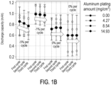
- FIG. 1B is a data diagram of a capacity decay rate of different weights of a metal plating layer on a hole material layer.
- FIG. 2 is a schematic diagram of a fabrication of a negative electrode structure according to an embodiment of the disclosure.
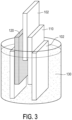
- FIG. 3 is a schematic diagram of a testing of a negative electrode structure applied to an aluminum battery according to an embodiment of the disclosure.
- a negative electrode structure 110 applied to an aluminum battery 100 includes a hole material layer 111 and a metal plating layer 112.
- the metal plating layer 112 is located on the hole material layer 111 such that the capacity decay rate of the aluminum battery is less than 5% per cycle.
- the negative electrode structure 110 applied to the aluminum battery 100 of the embodiment may increase the number of reaction sites on the surface of the negative electrode structure 110 by using the composite electrode design of the hole material layer 111 and the metal plating layer 112, thereby improving the performance of the aluminum battery 100 in terms of the capacity decay rate (less than 5% per cycle) and facilitating the scale-up production.
- the hole material layer 111 may be a high specific surface area material.
- the specific surface area of the hole material layer 111 is, for example, between 100m 2 /g and 3000m 2 /g. Since the hole material layer 111 has characteristics such as a hole structure and a high specific surface area, and the metal plating layer 112 is coated on the hole material layer 111, an active material may perform an oxidation-reduction electrochemical reaction more efficiently, but the disclosure is not limited thereto.
- the material of the hole material layer 111 includes activated carbon, natural graphite, artificial graphite, graphene, carbon black, soft carbon, hard carbon, mesophase graphite carbon microspheres, or a combination thereof, and the metal plating layer 112 is an aluminum metal plating layer, but the disclosure is not limited thereto.
- Other suitable non-carbon hole materials may also be used for the hole material layer 111.
- the metal plating layer 112 may be electroplated on the hole material layer 111 by ionic liquid 103.
- the ionic liquid 103 may include aluminum salt ionic liquid, so that when a current A flows to the hole material layer 111, an ion 10 (Al 2 Cl 7- ) is converted into an ion 20 (AlCl 4 -) through the reaction of formula (1): 4Al 2 Cl 7- +3e - - ⁇ Al+7AlCl 4- and a uniform aluminum metal plating layer is electroplated on the hole material layer 111 by using the aluminum salt ionic liquid.
- the hole material layer 111 may be disposed on a cathode of an electroplating device and an aluminum foil 101 may be disposed on an anode of an electroplating device to electroplate the aluminum metal on the hole material layer 111, but the disclosure is not limited thereto.
- the metal plating layer 112 may be located between a positive electrode structure 120 of the aluminum battery 100 and the hole material layer 111, and an electrolyte 130 is provided between the positive electrode structure 120 and the negative electrode structure 110.
- the positive electrode structure 120 and the electrolyte 130 may be selected according to actual design requirements and are not limited by the disclosure.
- the weight of the metal plating layer 112 on the hole material layer 111 is greater than 2mg/cm 2 , and the weight of the metal plating layer 112 on the hole material layer 111 is less than 100mg/cm 2 .
- the weight of the metal plating layer 112 on the hole material layer 111 is greater than 2mg/cm 2 , and the weight of the metal plating layer 112 on the hole material layer 111 is less than 100mg/cm 2 .
- the capacity decay rate of the aluminum battery is 5% per cycle; when the amount of aluminum plating is 4.27 mg/cm 2 , the capacity decay rate of the aluminum battery is 1% per cycle (less than 5% per cycle); when the amount of aluminum plating is 8.54 mg/cm 2 and 14.93 mg/cm 2 , the capacity decay rate of the aluminum battery is 0% per cycle (less than 5% per cycle). That is to say, the degree of improvement of the capacity decay rate is positively correlated with the weight of the metal plating layer 112 on the hole material layer 111.
- the positive electrode structure of the aluminum battery of FIG. 1B uses a graphite structure, and the electrolyte uses a chloroaluminate ionic liquid, and other compositions and specifications not described should be obtained by a person having ordinary skill in the art based on any content included in the spirit and the scope of the appended claims.
- the experimental data of FIG. 1B is obtained by a testing device of FIG. 3 .
- the testing device of FIG. 3 may fix the spacings between the negative electrode structure 110, the positive electrode structure 120, and the electrolyte 130 of the aluminum battery 100 by a fixing member 102 (such as a glass slide) and may fix the positions of the negative electrode structure 110 and the positive electrode structure 120 so as to carry out the test.
- the electrolyte 130 is aluminum halide and imidazole chloride salt
- the metal plating layer 112 is an aluminum metal plating layer
- a metal M converts the ion 20 (AlCl 4- ) into the ion 10 (Al 2 Cl 7- ) through the reaction of formula (2): Al+7AlCl 4- ⁇ 4Al 2 Cl 7- +3e - , so that the problem may be significantly improved with regards to the capacity decay caused by using only carbon-based materials as the negative electrodes of the aluminum batteries, where there is no aluminum source provided on the surface and which may result in a slow aluminum dissolution reaction and an incomplete delamination of the active material in the positive electrode.
- the amount of the aluminum dissolution of the negative electrode structure 110 may be increased to react with the ion 20 (AlCl 4- ) delaminated from the positive electrode structure 120 so as to form the ion 10 (Al 2 Cl 7- ).
- the ion 20 (AlCl 4- ) in the layer spacing of the positive electrode structure 120 may be delaminated and do not remain in the layer spacing substantially, thereby improving the problem of the gradual decay of the electricity caused by excessive active material remaining in the layer spacing during the discharge cycle which may affect the number of active material that may be intercalated at the positive electrode during the next charge cycle when the rate of the aluminum dissolution is less than the delamination rate of the positive electrode. That is, the number of active materials that may be intercalated during subsequent charge and discharge cycles may remain unchanged, thereby effectively improving the capacity decay.
- the negative electrode structure applied to the aluminum battery of the disclosure may increase the number of reaction sites on the surface of the negative electrode structure by using the composite electrode design of the hole material layer and the metal plating layer, thereby improving the performance of the aluminum battery in terms of the capacity decay rate (less than 5%/circle) and facilitating the scale-up production.
Landscapes
- Chemical & Material Sciences (AREA)
- Engineering & Computer Science (AREA)
- Chemical Kinetics & Catalysis (AREA)
- Electrochemistry (AREA)
- General Chemical & Material Sciences (AREA)
- Materials Engineering (AREA)
- Organic Chemistry (AREA)
- Metallurgy (AREA)
- Manufacturing & Machinery (AREA)
- Ceramic Engineering (AREA)
- Battery Electrode And Active Subsutance (AREA)
- Cell Electrode Carriers And Collectors (AREA)
- Secondary Cells (AREA)
Abstract
A negative electrode structure applied to an aluminum battery includes a hole material layer (111) and a metal plating layer (112). The metal plating layer (112) is located on the hole material layer (111) such that the capacity decay rate of the aluminum battery is less than 5% per cycle.
Description
- The disclosure relates to a negative electrode structure applied to an aluminum battery.
- Aluminum batteries, as electrochemical energy storage components, have advantages of good security and low cost. Furthermore, the capacity decay rate of the aluminum battery may be affected by the rate of the aluminum dissolution reaction on a negative electrode, and the rate of the aluminum dissolution reaction is closely related to the negative electrode structure. Therefore, how to design a more favorable negative electrode structure to improve the performance of the aluminum battery in terms of the capacity decay rate is indeed a challenge.
- The disclosure provides a negative electrode structure applied to an aluminum battery, which may improve performance of the aluminum battery in terms of a capacity decay rate and facilitate scale-up production.
- A negative electrode structure applied to an aluminum battery of the disclosure includes a hole material layer and a metal plating layer. The metal plating layer is located on the hole material layer such that a capacity decay rate of the aluminum battery is less than 5% per cycle.
- In an embodiment of the disclosure, a weight of the metal plating layer on the hole material layer is greater than 2 mg/cm 2.
- In an embodiment of the disclosure, the weight of the metal plating layer on the hole material layer is less than 100 mg/cm 2.
- In an embodiment of the disclosure, a specific surface area of the hole material layer is between 100 m 2 /g and 3000 m 2 /g.
- In an embodiment of the disclosure, a material of the hole material layer includes activated carbon, natural graphite, artificial graphite, graphene, carbon black, soft carbon, hard carbon, mesophase graphite carbon microspheres, or a combination thereof.
- In an embodiment of the disclosure, the metal plating layer is an aluminum metal plating layer.
- In an embodiment of the disclosure, the metal plating layer is electroplated on the hole material layer by ionic liquid.
- In an embodiment of the disclosure, the ionic liquid includes aluminum salt-based ionic liquid.
- In an embodiment of the disclosure, the metal plating layer is located between a positive electrode structure of the aluminum battery and the hole material layer of the aluminum battery.
- In an embodiment of the disclosure, the positive electrode structure includes an intercalation material.
- Based on the above, the negative electrode structure of the disclosure applied to the aluminum battery may increase the number of reaction sites on the surface of the negative electrode structure by using the composite electrode design of the hole material layer and the metal plating layer, thereby improving the performance of the aluminum battery in terms of the capacity decay rate (less than 5% per circle) and facilitating the scale-up production.
- In order to make the above-mentioned features and advantages of the disclosure clearer and easier to understand, the following embodiments are given and described in details with accompanying drawings as follows.
-
-
FIG. 1A is a schematic diagram of a negative electrode structure applied to an aluminum battery according to an embodiment of the disclosure. -
FIG. 1B is a data diagram of a capacity decay rate of different weights of a metal plating layer on a hole material layer. -
FIG. 2 is a schematic diagram of a fabrication of a negative electrode structure according to an embodiment of the disclosure. -
FIG. 3 is a schematic diagram of a testing of a negative electrode structure applied to an aluminum battery according to an embodiment of the disclosure. - Hereinafter, embodiments of the disclosure are described in details. However, the embodiments are exemplary, and the disclosure is not limited hereto. The disclosure is defined by the scope of the claims.
- Exemplary embodiments of the disclosure will be fully described below with reference to the drawings, but the disclosure may also be embodied in many different forms and should not be construed as limited to the embodiments described herein. In the drawings, for the sake of clarity, the sizes and the thicknesses of various regions, parts, and layers may not be drawn in actual scale. In order to facilitate understanding, the same components in the following description will be described with the same reference numerals.
- Directional terms (e.g., up, down, right, left, front, back, top, bottom) as used herein are used pictorially by reference only and are not intended to imply an absolute orientation.
- Unless otherwise defined, all terms (including technical and scientific terms) used herein have the same meaning as commonly understood by a person having ordinary skill in the art.
-
FIG. 1A is a schematic diagram of a negative electrode structure applied to an aluminum battery according to an embodiment of the disclosure.FIG. 1B is a data diagram of a capacity decay rate of different weights of a metal plating layer on a hole material layer.FIG. 2 is a schematic diagram of a fabrication of a negative electrode structure according to an embodiment of the disclosure.FIG. 3 is a schematic diagram of a testing of a negative electrode structure applied to an aluminum battery according to an embodiment of the disclosure. - Please refer to
FIG. 1A ,FIG. 1B ,FIG. 2 , andFIG. 3 . In the embodiment, anegative electrode structure 110 applied to analuminum battery 100 includes ahole material layer 111 and ametal plating layer 112. Themetal plating layer 112 is located on thehole material layer 111 such that the capacity decay rate of the aluminum battery is less than 5% per cycle. Accordingly, thenegative electrode structure 110 applied to thealuminum battery 100 of the embodiment may increase the number of reaction sites on the surface of thenegative electrode structure 110 by using the composite electrode design of thehole material layer 111 and themetal plating layer 112, thereby improving the performance of thealuminum battery 100 in terms of the capacity decay rate (less than 5% per cycle) and facilitating the scale-up production. - In some embodiments, the
hole material layer 111 may be a high specific surface area material. The specific surface area of thehole material layer 111 is, for example, between 100m2/g and 3000m2/g. Since thehole material layer 111 has characteristics such as a hole structure and a high specific surface area, and themetal plating layer 112 is coated on thehole material layer 111, an active material may perform an oxidation-reduction electrochemical reaction more efficiently, but the disclosure is not limited thereto. - In some embodiments, the material of the
hole material layer 111 includes activated carbon, natural graphite, artificial graphite, graphene, carbon black, soft carbon, hard carbon, mesophase graphite carbon microspheres, or a combination thereof, and themetal plating layer 112 is an aluminum metal plating layer, but the disclosure is not limited thereto. Other suitable non-carbon hole materials may also be used for thehole material layer 111. - In some embodiments, as shown in
FIG. 2 , themetal plating layer 112 may be electroplated on thehole material layer 111 byionic liquid 103. Further, when themetal plating layer 112 is an aluminum metal plating layer, theionic liquid 103 may include aluminum salt ionic liquid, so that when a current A flows to thehole material layer 111, an ion 10 (Al2Cl7-) is converted into an ion 20 (AlCl4-) through the reaction of formula (1): 4Al2Cl7-+3e- -→Al+7AlCl4-and a uniform aluminum metal plating layer is electroplated on thehole material layer 111 by using the aluminum salt ionic liquid. Here, thehole material layer 111 may be disposed on a cathode of an electroplating device and analuminum foil 101 may be disposed on an anode of an electroplating device to electroplate the aluminum metal on thehole material layer 111, but the disclosure is not limited thereto. - In some embodiments, the
metal plating layer 112 may be located between apositive electrode structure 120 of thealuminum battery 100 and thehole material layer 111, and anelectrolyte 130 is provided between thepositive electrode structure 120 and thenegative electrode structure 110. Thepositive electrode structure 120 and theelectrolyte 130 may be selected according to actual design requirements and are not limited by the disclosure. - In some embodiments, the weight of the
metal plating layer 112 on thehole material layer 111 is greater than 2mg/cm2, and the weight of themetal plating layer 112 on thehole material layer 111 is less than 100mg/cm2. For example, as shown inFIG. 1B , when themetal plating layer 112 is an aluminum metal plating layer, and the amount of aluminum plating is 0 mg/cm2 (that is, there is nometal plating layer 112 formed), the capacity decay rate of the aluminum battery is 5% per cycle; when the amount of aluminum plating is 4.27 mg/cm2, the capacity decay rate of the aluminum battery is 1% per cycle (less than 5% per cycle); when the amount of aluminum plating is 8.54 mg/cm2 and 14.93 mg/cm2, the capacity decay rate of the aluminum battery is 0% per cycle (less than 5% per cycle). That is to say, the degree of improvement of the capacity decay rate is positively correlated with the weight of themetal plating layer 112 on thehole material layer 111. - Here, the positive electrode structure of the aluminum battery of
FIG. 1B uses a graphite structure, and the electrolyte uses a chloroaluminate ionic liquid, and other compositions and specifications not described should be obtained by a person having ordinary skill in the art based on any content included in the spirit and the scope of the appended claims. In addition, the experimental data ofFIG. 1B is obtained by a testing device ofFIG. 3 . The testing device ofFIG. 3 may fix the spacings between thenegative electrode structure 110, thepositive electrode structure 120, and theelectrolyte 130 of thealuminum battery 100 by a fixing member 102 (such as a glass slide) and may fix the positions of thenegative electrode structure 110 and thepositive electrode structure 120 so as to carry out the test. - In some embodiments, when the
positive electrode structure 120 is an intercalation material, theelectrolyte 130 is aluminum halide and imidazole chloride salt, and themetal plating layer 112 is an aluminum metal plating layer, a large amount of aluminum dissolution reaction occurs on the surface of thenegative electrode structure 110 during the discharge cycle. A metal M converts the ion 20 (AlCl4-) into the ion 10 (Al2Cl7-) through the reaction of formula (2): Al+7AlCl4-→4Al2Cl7-+3e-, so that the problem may be significantly improved with regards to the capacity decay caused by using only carbon-based materials as the negative electrodes of the aluminum batteries, where there is no aluminum source provided on the surface and which may result in a slow aluminum dissolution reaction and an incomplete delamination of the active material in the positive electrode. That is to say, by using the composite electrode design of thehole material layer 111 having a high specific surface area and themetal plating layer 112, the amount of the aluminum dissolution of thenegative electrode structure 110 may be increased to react with the ion 20 (AlCl4-) delaminated from thepositive electrode structure 120 so as to form the ion 10 (Al2Cl7-). As a result, the ion 20 (AlCl4-) in the layer spacing of thepositive electrode structure 120 may be delaminated and do not remain in the layer spacing substantially, thereby improving the problem of the gradual decay of the electricity caused by excessive active material remaining in the layer spacing during the discharge cycle which may affect the number of active material that may be intercalated at the positive electrode during the next charge cycle when the rate of the aluminum dissolution is less than the delamination rate of the positive electrode. That is, the number of active materials that may be intercalated during subsequent charge and discharge cycles may remain unchanged, thereby effectively improving the capacity decay. - In summary, the negative electrode structure applied to the aluminum battery of the disclosure may increase the number of reaction sites on the surface of the negative electrode structure by using the composite electrode design of the hole material layer and the metal plating layer, thereby improving the performance of the aluminum battery in terms of the capacity decay rate (less than 5%/circle) and facilitating the scale-up production.
Claims (10)
- A negative electrode structure (110), applied to an aluminum battery (100), comprising:a hole material layer (111); anda metal plating layer (112), located on the hole material layer (111), such that a capacity decay rate of the aluminum battery (100) is less than 5% per cycle.
- The negative electrode structure (110) according to claim 1, wherein a weight of the metal plating layer (112) on the hole material layer (111) is greater than 2mg/cm2.
- The negative electrode structure (110) according to claim 2, wherein the weight of the metal plating layer (112) on the hole material layer (111) is less than 100mg/cm2.
- The negative electrode structure (110) according to claim 1, wherein a specific surface area of the hole material layer (111) is between 100m2/g and 3000m2/g.
- The negative electrode structure (110) according to claim 1, wherein a material of the hole material layer (111) comprises activated carbon, natural graphite, artificial graphite, graphene, carbon black, soft carbon, hard carbon, mesophase graphite carbon microspheres, or a combination thereof.
- The negative electrode structure (110) according to claim 1, wherein the metal plating layer (112) is an aluminum metal plating layer (112).
- The negative electrode structure (110) according to claim 1, wherein the metal plating layer (112) is electroplated on the hole material layer (111) by an ionic liquid (103).
- The negative electrode structure (110) according to claim 7, wherein the ionic liquid (103) comprises an aluminum salt-based ionic liquid.
- The negative electrode structure (110) according to claim 1, wherein the metal plating layer (112) is located between a positive electrode structure (120) of the aluminum battery (100) and the hole material layer (111).
- The negative electrode structure (110) according to claim 9, wherein the negative electrode structure comprises an intercalation material.
Applications Claiming Priority (1)
| Application Number | Priority Date | Filing Date | Title |
|---|---|---|---|
| TW111140965A TWI834359B (en) | 2022-10-27 | 2022-10-27 | Negative electrode structure applied to alluminum battery |
Publications (1)
| Publication Number | Publication Date |
|---|---|
| EP4372846A1 true EP4372846A1 (en) | 2024-05-22 |
Family
ID=86942613
Family Applications (1)
| Application Number | Title | Priority Date | Filing Date |
|---|---|---|---|
| EP23180612.6A Pending EP4372846A1 (en) | 2022-10-27 | 2023-06-21 | Negative electrode structure applied to an aluminum battery |
Country Status (5)
| Country | Link |
|---|---|
| US (1) | US20240145670A1 (en) |
| EP (1) | EP4372846A1 (en) |
| JP (1) | JP7709773B2 (en) |
| KR (1) | KR20240059528A (en) |
| TW (1) | TWI834359B (en) |
Families Citing this family (2)
| Publication number | Priority date | Publication date | Assignee | Title |
|---|---|---|---|---|
| TWI883363B (en) * | 2022-12-23 | 2025-05-11 | 亞福儲能股份有限公司 | Negative electrode structure applied to alluminum battery |
| TWI888790B (en) * | 2023-01-31 | 2025-07-01 | 亞福儲能股份有限公司 | Alluminum battery |
Citations (3)
| Publication number | Priority date | Publication date | Assignee | Title |
|---|---|---|---|---|
| CN104183835A (en) * | 2014-08-22 | 2014-12-03 | 南京中储新能源有限公司 | Aluminium carbon aerogel composite material and secondary battery adopting aluminium carbon aerogel composite material as negative electrode |
| US20180233747A1 (en) * | 2017-02-16 | 2018-08-16 | Nanotek Instruments, Inc. | Aluminum Secondary Battery Having an Exfoliated Graphite-Based High-Capacity Cathode and Manufacturing Method |
| US20200212476A1 (en) * | 2018-12-27 | 2020-07-02 | Industrial Technology Research Institute | Metal-ion battery |
Family Cites Families (5)
| Publication number | Priority date | Publication date | Assignee | Title |
|---|---|---|---|---|
| JP3940692B2 (en) * | 2003-03-28 | 2007-07-04 | 株式会社東芝 | Negative electrode material for aluminum battery and aluminum primary battery |
| TWI622214B (en) * | 2016-09-22 | 2018-04-21 | 財團法人工業技術研究院 | Metal-ion secondary battery |
| JP6695614B2 (en) * | 2017-03-10 | 2020-05-20 | ineova株式会社 | Metal negative battery |
| JP2020043043A (en) * | 2018-09-11 | 2020-03-19 | 公昭 佐藤 | Anode material for aluminum battery |
| CN109742320A (en) * | 2018-12-29 | 2019-05-10 | 北京工业大学 | A kind of three-dimensional porous aluminum honeycomb and its aluminum cell application |
-
2022
- 2022-10-27 TW TW111140965A patent/TWI834359B/en active
-
2023
- 2023-05-31 US US18/326,009 patent/US20240145670A1/en active Pending
- 2023-06-21 EP EP23180612.6A patent/EP4372846A1/en active Pending
- 2023-07-22 JP JP2023119528A patent/JP7709773B2/en active Active
- 2023-07-24 KR KR1020230096360A patent/KR20240059528A/en active Pending
Patent Citations (3)
| Publication number | Priority date | Publication date | Assignee | Title |
|---|---|---|---|---|
| CN104183835A (en) * | 2014-08-22 | 2014-12-03 | 南京中储新能源有限公司 | Aluminium carbon aerogel composite material and secondary battery adopting aluminium carbon aerogel composite material as negative electrode |
| US20180233747A1 (en) * | 2017-02-16 | 2018-08-16 | Nanotek Instruments, Inc. | Aluminum Secondary Battery Having an Exfoliated Graphite-Based High-Capacity Cathode and Manufacturing Method |
| US20200212476A1 (en) * | 2018-12-27 | 2020-07-02 | Industrial Technology Research Institute | Metal-ion battery |
Non-Patent Citations (1)
| Title |
|---|
| MUÑOZ-TORRERO DAVID ET AL: "Investigation of different anode materials for aluminium rechargeable batteries", JOURNAL OF POWER SOURCES, vol. 374, 13 November 2017 (2017-11-13), pages 77 - 83, XP085292595, ISSN: 0378-7753, DOI: 10.1016/J.JPOWSOUR.2017.11.032 * |
Also Published As
| Publication number | Publication date |
|---|---|
| JP2024064985A (en) | 2024-05-14 |
| TWI834359B (en) | 2024-03-01 |
| US20240145670A1 (en) | 2024-05-02 |
| TW202418629A (en) | 2024-05-01 |
| KR20240059528A (en) | 2024-05-07 |
| JP7709773B2 (en) | 2025-07-17 |
Similar Documents
| Publication | Publication Date | Title |
|---|---|---|
| Han et al. | Hydrophilic silica spheres layer as ions shunt for enhanced Zn metal anode | |
| Qin et al. | Achieving high-rate and high-capacity Zn metal anodes via a three-in-one carbon protective layer | |
| Wang et al. | Anti-catalytic and zincophilic layers integrated zinc anode towards efficient aqueous batteries for ultra-long cycling stability | |
| Xue et al. | Highly reversible zinc metal anodes enabled by a three-dimensional silver host for aqueous batteries | |
| EP2639341B1 (en) | Method for producing aluminium foil | |
| EP4372846A1 (en) | Negative electrode structure applied to an aluminum battery | |
| Zhang et al. | Highly robust zinc metal anode directed by organic–inorganic synergistic interfaces for wearable aqueous zinc battery | |
| Cui et al. | Fluorine enhanced nucleophilicity of TiO2 nanorod arrays: A general approach for dendrite-free anodes towards high-performance metal batteries | |
| JP5788062B1 (en) | Negative electrode current collector for all solid state battery and all solid state battery | |
| He et al. | Aluminum dendrite suppression by graphite coated anodes of Al-metal batteries | |
| CN102668199A (en) | Aluminum foil which supports carbonaceous particles scattered thereon | |
| CN113991191A (en) | Aqueous zinc bromine battery | |
| CN106381513A (en) | Preparation method and application of multi-stage nanosheet zinc oxide | |
| Yao et al. | An “immobilizing and relocating” strategy for a highly reversible metallic zinc anode | |
| Zhang et al. | Regulation of the solvation structure and electrode interface using a succinic acid additive for highly stable aqueous Zn batteries | |
| Bu et al. | Bio-inspired hormonic electrolyte: negative feedback for ultra-stable zinc anodes | |
| CN116315180B (en) | Preparation and application of tin-protected three-dimensional zinc metal anode with high cycle stability | |
| Sun et al. | Zincophilic Cu/flexible polymer heterogeneous interfaces ensuring the stability of zinc metal anodes | |
| Wang et al. | A functional hydrogel electrolyte doped with graphene oxide enabling ultra-long lifespan zinc metal batteries by inducing oriented deposition | |
| US10305139B2 (en) | Energy storage system | |
| JP2015198089A (en) | Electrolyte composition | |
| Lyu et al. | Dendrite suppression by scalable acid treatment of zinc metal anodes for aqueous zinc-ion batteries | |
| US20230014483A1 (en) | Electrode for lithium-ion battery and lithium-ion battery comprising the same | |
| CN108063271A (en) | A kind of half flow battery | |
| Yang et al. | A robust in situ adaptive artificial interface for dead-lithium-free lithium metal batteries |
Legal Events
| Date | Code | Title | Description |
|---|---|---|---|
| PUAI | Public reference made under article 153(3) epc to a published international application that has entered the european phase |
Free format text: ORIGINAL CODE: 0009012 |
|
| STAA | Information on the status of an ep patent application or granted ep patent |
Free format text: STATUS: REQUEST FOR EXAMINATION WAS MADE |
|
| 17P | Request for examination filed |
Effective date: 20230621 |
|
| AK | Designated contracting states |
Kind code of ref document: A1 Designated state(s): AL AT BE BG CH CY CZ DE DK EE ES FI FR GB GR HR HU IE IS IT LI LT LU LV MC ME MK MT NL NO PL PT RO RS SE SI SK SM TR |
|
| RBV | Designated contracting states (corrected) |
Designated state(s): AL AT BE BG CH CY CZ DE DK EE ES FI FR GB GR HR HU IE IS IT LI LT LU LV MC ME MK MT NL NO PL PT RO RS SE SI SK SM TR |