EP4372833B1 - Method of fabricating a pre-lithiated electrode and lithium-ion battery cell - Google Patents
Method of fabricating a pre-lithiated electrode and lithium-ion battery cell Download PDFInfo
- Publication number
- EP4372833B1 EP4372833B1 EP22208678.7A EP22208678A EP4372833B1 EP 4372833 B1 EP4372833 B1 EP 4372833B1 EP 22208678 A EP22208678 A EP 22208678A EP 4372833 B1 EP4372833 B1 EP 4372833B1
- Authority
- EP
- European Patent Office
- Prior art keywords
- electrode
- layer
- lithium
- lithiated
- pet
- Prior art date
- Legal status (The legal status is an assumption and is not a legal conclusion. Google has not performed a legal analysis and makes no representation as to the accuracy of the status listed.)
- Active
Links
Images

Classifications
-
- H—ELECTRICITY
- H01—ELECTRIC ELEMENTS
- H01M—PROCESSES OR MEANS, e.g. BATTERIES, FOR THE DIRECT CONVERSION OF CHEMICAL ENERGY INTO ELECTRICAL ENERGY
- H01M4/00—Electrodes
- H01M4/02—Electrodes composed of, or comprising, active material
- H01M4/13—Electrodes for accumulators with non-aqueous electrolyte, e.g. for lithium-accumulators; Processes of manufacture thereof
- H01M4/134—Electrodes based on metals, Si or alloys
-
- H—ELECTRICITY
- H01—ELECTRIC ELEMENTS
- H01M—PROCESSES OR MEANS, e.g. BATTERIES, FOR THE DIRECT CONVERSION OF CHEMICAL ENERGY INTO ELECTRICAL ENERGY
- H01M4/00—Electrodes
- H01M4/02—Electrodes composed of, or comprising, active material
- H01M4/04—Processes of manufacture in general
- H01M4/0402—Methods of deposition of the material
- H01M4/0404—Methods of deposition of the material by coating on electrode collectors
-
- H—ELECTRICITY
- H01—ELECTRIC ELEMENTS
- H01M—PROCESSES OR MEANS, e.g. BATTERIES, FOR THE DIRECT CONVERSION OF CHEMICAL ENERGY INTO ELECTRICAL ENERGY
- H01M4/00—Electrodes
- H01M4/02—Electrodes composed of, or comprising, active material
- H01M4/13—Electrodes for accumulators with non-aqueous electrolyte, e.g. for lithium-accumulators; Processes of manufacture thereof
- H01M4/139—Processes of manufacture
-
- H—ELECTRICITY
- H01—ELECTRIC ELEMENTS
- H01M—PROCESSES OR MEANS, e.g. BATTERIES, FOR THE DIRECT CONVERSION OF CHEMICAL ENERGY INTO ELECTRICAL ENERGY
- H01M10/00—Secondary cells; Manufacture thereof
- H01M10/05—Accumulators with non-aqueous electrolyte
- H01M10/052—Li-accumulators
- H01M10/0525—Rocking-chair batteries, i.e. batteries with lithium insertion or intercalation in both electrodes; Lithium-ion batteries
-
- H—ELECTRICITY
- H01—ELECTRIC ELEMENTS
- H01M—PROCESSES OR MEANS, e.g. BATTERIES, FOR THE DIRECT CONVERSION OF CHEMICAL ENERGY INTO ELECTRICAL ENERGY
- H01M10/00—Secondary cells; Manufacture thereof
- H01M10/42—Methods or arrangements for servicing or maintenance of secondary cells or secondary half-cells
- H01M10/4235—Safety or regulating additives or arrangements in electrodes, separators or electrolyte
-
- H—ELECTRICITY
- H01—ELECTRIC ELEMENTS
- H01M—PROCESSES OR MEANS, e.g. BATTERIES, FOR THE DIRECT CONVERSION OF CHEMICAL ENERGY INTO ELECTRICAL ENERGY
- H01M4/00—Electrodes
- H01M4/02—Electrodes composed of, or comprising, active material
- H01M4/04—Processes of manufacture in general
- H01M4/043—Processes of manufacture in general involving compressing or compaction
- H01M4/0435—Rolling or calendering
-
- H—ELECTRICITY
- H01—ELECTRIC ELEMENTS
- H01M—PROCESSES OR MEANS, e.g. BATTERIES, FOR THE DIRECT CONVERSION OF CHEMICAL ENERGY INTO ELECTRICAL ENERGY
- H01M4/00—Electrodes
- H01M4/02—Electrodes composed of, or comprising, active material
- H01M4/13—Electrodes for accumulators with non-aqueous electrolyte, e.g. for lithium-accumulators; Processes of manufacture thereof
- H01M4/131—Electrodes based on mixed oxides or hydroxides, or on mixtures of oxides or hydroxides, e.g. LiCoOx
-
- H—ELECTRICITY
- H01—ELECTRIC ELEMENTS
- H01M—PROCESSES OR MEANS, e.g. BATTERIES, FOR THE DIRECT CONVERSION OF CHEMICAL ENERGY INTO ELECTRICAL ENERGY
- H01M4/00—Electrodes
- H01M4/02—Electrodes composed of, or comprising, active material
- H01M4/13—Electrodes for accumulators with non-aqueous electrolyte, e.g. for lithium-accumulators; Processes of manufacture thereof
- H01M4/133—Electrodes based on carbonaceous material, e.g. graphite-intercalation compounds or CFx
-
- H—ELECTRICITY
- H01—ELECTRIC ELEMENTS
- H01M—PROCESSES OR MEANS, e.g. BATTERIES, FOR THE DIRECT CONVERSION OF CHEMICAL ENERGY INTO ELECTRICAL ENERGY
- H01M4/00—Electrodes
- H01M4/02—Electrodes composed of, or comprising, active material
- H01M4/13—Electrodes for accumulators with non-aqueous electrolyte, e.g. for lithium-accumulators; Processes of manufacture thereof
- H01M4/139—Processes of manufacture
- H01M4/1393—Processes of manufacture of electrodes based on carbonaceous material, e.g. graphite-intercalation compounds or CFx
-
- H—ELECTRICITY
- H01—ELECTRIC ELEMENTS
- H01M—PROCESSES OR MEANS, e.g. BATTERIES, FOR THE DIRECT CONVERSION OF CHEMICAL ENERGY INTO ELECTRICAL ENERGY
- H01M4/00—Electrodes
- H01M4/02—Electrodes composed of, or comprising, active material
- H01M4/13—Electrodes for accumulators with non-aqueous electrolyte, e.g. for lithium-accumulators; Processes of manufacture thereof
- H01M4/139—Processes of manufacture
- H01M4/1395—Processes of manufacture of electrodes based on metals, Si or alloys
-
- H—ELECTRICITY
- H01—ELECTRIC ELEMENTS
- H01M—PROCESSES OR MEANS, e.g. BATTERIES, FOR THE DIRECT CONVERSION OF CHEMICAL ENERGY INTO ELECTRICAL ENERGY
- H01M4/00—Electrodes
- H01M4/02—Electrodes composed of, or comprising, active material
- H01M4/36—Selection of substances as active materials, active masses, active liquids
- H01M4/38—Selection of substances as active materials, active masses, active liquids of elements or alloys
- H01M4/381—Alkaline or alkaline earth metals elements
- H01M4/382—Lithium
-
- H—ELECTRICITY
- H01—ELECTRIC ELEMENTS
- H01M—PROCESSES OR MEANS, e.g. BATTERIES, FOR THE DIRECT CONVERSION OF CHEMICAL ENERGY INTO ELECTRICAL ENERGY
- H01M4/00—Electrodes
- H01M4/02—Electrodes composed of, or comprising, active material
- H01M4/36—Selection of substances as active materials, active masses, active liquids
- H01M4/58—Selection of substances as active materials, active masses, active liquids of inorganic compounds other than oxides or hydroxides, e.g. sulfides, selenides, tellurides, halogenides or LiCoFy; of polyanionic structures, e.g. phosphates, silicates or borates
- H01M4/583—Carbonaceous material, e.g. graphite-intercalation compounds or CFx
- H01M4/587—Carbonaceous material, e.g. graphite-intercalation compounds or CFx for inserting or intercalating light metals
-
- H—ELECTRICITY
- H01—ELECTRIC ELEMENTS
- H01M—PROCESSES OR MEANS, e.g. BATTERIES, FOR THE DIRECT CONVERSION OF CHEMICAL ENERGY INTO ELECTRICAL ENERGY
- H01M4/00—Electrodes
- H01M4/02—Electrodes composed of, or comprising, active material
- H01M2004/026—Electrodes composed of, or comprising, active material characterised by the polarity
- H01M2004/027—Negative electrodes
-
- H—ELECTRICITY
- H01—ELECTRIC ELEMENTS
- H01M—PROCESSES OR MEANS, e.g. BATTERIES, FOR THE DIRECT CONVERSION OF CHEMICAL ENERGY INTO ELECTRICAL ENERGY
- H01M4/00—Electrodes
- H01M4/02—Electrodes composed of, or comprising, active material
- H01M2004/026—Electrodes composed of, or comprising, active material characterised by the polarity
- H01M2004/028—Positive electrodes
-
- Y—GENERAL TAGGING OF NEW TECHNOLOGICAL DEVELOPMENTS; GENERAL TAGGING OF CROSS-SECTIONAL TECHNOLOGIES SPANNING OVER SEVERAL SECTIONS OF THE IPC; TECHNICAL SUBJECTS COVERED BY FORMER USPC CROSS-REFERENCE ART COLLECTIONS [XRACs] AND DIGESTS
- Y02—TECHNOLOGIES OR APPLICATIONS FOR MITIGATION OR ADAPTATION AGAINST CLIMATE CHANGE
- Y02E—REDUCTION OF GREENHOUSE GAS [GHG] EMISSIONS, RELATED TO ENERGY GENERATION, TRANSMISSION OR DISTRIBUTION
- Y02E60/00—Enabling technologies; Technologies with a potential or indirect contribution to GHG emissions mitigation
- Y02E60/10—Energy storage using batteries
Definitions
- the present invention is directed to a method of fabricating a pre-lithiated electrode and a lithium-ion battery cell comprising said pre-lithiated electrode.
- Li-ion batteries have played a role in the development of current generation mobile devices, microelectronics and electric vehicles.
- a typical Li-ion battery is made of a positive electrode (cathode), a negative electrode (anode), an electrolyte to conduct ions, a porous separator membrane, which is generally an electrical insulator, between the two electrodes to keep them physically apart, and a surrounding packaging.
- the rapid advancement and complex requirements of the energy storage industry requires lithium-ion batteries with improved energy density and cycle life.
- the improved energy density can be achieved with anodes containing silicon or silicon oxide.
- the drawback of this material is a higher demand of lithium leading to reduced cycle life, i.e. less cyclable lithium.
- Reduced cyclable lithium results in a reduced usable cell capacity.
- the addition of lithium during lithium-ion battery production, known as pre-lithiation, is used to compensate for these lithium losses.
- anode pre-lithiation methods exist including chemical pre-lithiation, electrochemical pre-lithiation, and stabilized lithium metal powder.
- US 2022/0052307 A1 discloses an in-line contact pre-lithiation. Further, the application of thin lithium foil for direct contact pre-lithiation of anodes within lithium ion battery production is disclosed by Benedikt Stumper et al., Procedia CIRP 93(2020), 156-161 .
- the problem underlying the present invention is to provide an improved method for fabricating a pre-lithiated electrode and a lithium-ion battery cell comprising said pre-lithiated electrode, said method being industrially applicable and allowing efficient and homogeneous transfer of lithium to the electrode without compromising the quality of the electrode.
- One aspect of the invention relates to a method of fabricating a pre-lithiated electrode, comprising:
- a further aspect of the invention relates to a lithium-ion battery cell, comprising:
- said method further comprises separating the PET sheet from the surface of the layer of anode material to form the pre-lithiated electrode.
- the PET layer has a thickness of about 20 ⁇ m to about 200 ⁇ m, more preferably of about 30 ⁇ m to 80 ⁇ m, in particular about 50 ⁇ m.
- the PET layer further comprises a release layer.
- said release layer has a thickness of about 0.005 ⁇ m to about 2 ⁇ m.
- calendering the layer of lithium metal comprises applying uniform pressure to a back surface of the carrier substrate, wherein the uniform pressure is a pressure ranging from about 1.9 MPa to about 8.9 MPa, preferably from about 3.2 MPa to about 5.3 MPa (not according to the invention unless embraced by the claims).
- Calendering the layer of lithium metal and the prefabricated electrode together comprises transferring the layer of lithium metal and the prefabricated electrode through a pair of calendering rolls.
- the method further comprises heating the front roll to a temperature in the range of from about 40°C to about 75°C, more preferably from about 60°C to about 70°C, in particular about 65°C.
- the method further comprises heating the back roll to a temperature in the range of from about 40°C to about 75°C, more preferably from about 60°C to about 70°C, in particular about 65°C.
- the prefabricated electrode is a negative electrode comprising a Cu carrier foil.
- said Cu carrier foil has a thickness of about 6 ⁇ m to about 12 ⁇ m, in particular about 8 ⁇ m.
- the prefabricated electrode is a negative electrode comprising a carbonaceous material, silicon, silicon oxide or combinations thereof.
- the carbonaceous material is selected from natural graphite, artificial graphite, or combinations thereof.
- the prefabricated electrode is a negative electrode having a coating, said coating preferably comprising SiO y C z , wherein y is from 0 to 2 and z is 0 or 1.
- the coating is a double-sided coating.
- the coating has a thickness of about 10 ⁇ m to about 80 ⁇ m.
- the layer of lithium metal has a thickness from about 3 ⁇ m to about 15 ⁇ m, more preferably from about 6 ⁇ m to about 12 ⁇ m, in particular about 9.3 ⁇ m.
- the lithium layer needs to be passivated, preferably by CO 2 .
- the gap between the calendering rolls is from about 160 ⁇ m to about 200 ⁇ m, preferably from about 170 ⁇ m to about 190 ⁇ m, more preferably about 180 ⁇ m.
- the pressure applied to the back surface of the carrier substrate can be defined in kN.
- Calendering the layer of lithium metal comprises applying uniform pressure to a back surface of the carrier substrate, wherein the uniform pressure is a pressure ranging from about 0.7 kN to about 0.8 kN, preferably about 0.75 kN.
- the method further comprises incorporating the pre-lithiated electrode into an electrochemical cell further comprising a positive electrode, a separator, and an electrolyte.
- a further aspect of the invention relates to a lithium-ion battery cell, comprising:
- each of the pre-lithiated electrode and the positive electrode are in a fully charged position.
- each of the pre-lithiated electrode and the positive electrode are in a partially charged position.
- the pre-lithiated electrode is completely lithiated in the fully charged position and the positive electrode is completely delithiated in the fully charged position.
- the present specification is not limited to the use of a Li-PET sheet, although only the use of a Li-PET sheet is embraced by the claims.
- the present specification therefore discloses a method of fabricating a pre-lithiated electrode, comprising:
- the carrier substrate is a PET substrate.
- the carrier substrate is a sheet.
- the preferred embodiments set out above for claimed method including the use of a Li-PET sheet are also applicable to the method including the use of a carrier substrate.
- the method is implemented as a roll-to-roll process.
- sheet as used herein is intended to designate a flexible material to which lithium is applied.
- the term is not limited to a specific geometrical shape, such as a layer, but also includes material that is wound into a roll.
- the following describes the claimed method of fabricating a pre-lithiated electrode and the claimed lithium-ion battery cell.
- each of the terms “comprising', “having” and “containing”, including grammatical variants thereof, are meant in a non-exhaustive sense to mean “including”, but not necessarily “composed of”, and does not exclude elements in addition to those explicitly recited as being present.
- the terms “comprising”, “having” and “containing”, and grammatical variants thereof, indicate that components other than those explicitly recited may, but need not, be present. As such these terms include as a limiting case embodiments in which no other elements than those recited are present, e.g. in the commonly accepted sense of "consisting of”.
- PET denotes the known polymeric material polyethylene terephthalate.
- PET also includes a derivative of PET.
- the PET or the derivative of PET can be replaced by a carrier substrate, provided that the carrier substrate is flexible and ensures the adhesion of the lithium layer and its release under pressure, ensures the adhesion of the release layer, is chemically inert with respect to the release layer and lithium, and is stable under pressure in the selected pressure range.
- any feature within any aspect or embodiment of the invention may be combined with any feature within any other aspect or embodiment of the invention, and the skilled person understands such combination as being encompassed in the original disclosure of the present application.
- the term “about” shall be understood as encompassing and disclosing a range of variability above and below an indicated specific value, said percentage values being relative to the specific recited value itself, as follows.
- the term “about” may denote variability of ⁇ 5.0%.
- the term “about” may denote variability of ⁇ 4.0%.
- the term “about” may denote variability of ⁇ 3.0%.
- the term “about” may denote variability of ⁇ 2.0%.
- the term “about” may denote variability of ⁇ 1.0%.
- the term “about”, in reference to the particular recited value, may denote that exact particular value itself, irrespective of any explicit mention that this exact particular value is included; even in the absence of an explicit indication that the term “about” includes the particular exact recited value, this exact particular value is still included in the range of variation created by the term “about”, and is therefore disclosed.
- the pre-lithiation method described herein is applicable to Li-ion batteries using solid electrolytes (e.g., solid-state batteries) as well as Li-ion batteries, which use liquid or polymer electrolytes.
- solid electrolytes e.g., solid-state batteries
- Li-ion batteries which use liquid or polymer electrolytes.
- the claimed method involves the pre-lithiation of anode materials with a lithium coated substrate, preferably PET, by way of direct contact.
- Direct contact is an effective way to pre-lithiate the anode material as this creates excellent surface contact between the lithium and the anode layer.
- the method described herein can be slotted into current battery production lines.
- the carrier substrate for lithium preferably PET, is a flexible substrate, which can be used in roll-to-roll coating.
- the calender rolls must be about 100% cylindrical to ensure uniform pressure distribution. Uniform pressure distribution means a pressure distribution on the surface of no more than +/-5%.
- the front roll is the roll that points to the subsequent process and the back roll is the roll that points away from the subsequent process.
- roll In a roll-to-roll process, roll is defined as coiled strip material. During the process run, the unwound material is in the process as a strip and can then be separated directly into electrodes or rewound as a roll. This roll can have a cyclindrical or substantially cyclindrical shape.
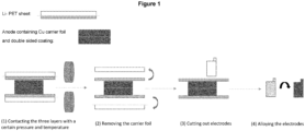
- Figures 1 illustrates a material flow according to the invention. This material flow is further illustrated by pictures in Figures 2 to 5 .
- the material flow in Figure 1 can be correlated to the pictures in Figures 2 to 5 as follows:
- the Li-PET sheet is pressed to an anode, which is preferably a Cu carrier foil having a double-sided coating containing SiO y C z , wherein y is 0-2 and z is 0 or 1.
- anode which is preferably a Cu carrier foil having a double-sided coating containing SiO y C z , wherein y is 0-2 and z is 0 or 1.
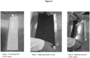
- FIGS 2 to 5 further illustrate the material flow according to Figure 1 as described above.
- Figure 2 show the provision of a first Li-PET sheet (step 1), the aligning of an anode on top of said first Li-PET sheet (step 2), and the aligning of a second Li-PET sheet on top of the anode to achieve a three-layered structure of Li-PET sheet/anode/Li-PET sheet (step 3).
- Figure 3 shows the calendering of the three-layered structure of Li-PET sheet/anode/Li-PET sheet of Figure 2 (step 4) and the removal of the carrier substrate (PET) to obtain a pre-lithiated anode sheet (step 5).
- the calendering of the three-layered structure of Li-PET sheet/anode/Li-PET sheet according to step 4 is preferably carried out with a front roll having a temperature in the range of from about 40°C to about 75°C, more preferably from about 60°C to about 70°C, and in particular about 65°C, and a back roll having preferably a temperature in the range of from about 40°C to about 75°C, more preferably from about 60°C to about 70°C, and in particular about 65°C.
- a homogeneous transfer of lithium can, however, also be achieved at room temperature, as discussed below.
- the friction between the calendering rolls can be within the range of about +/- 2%.
- the sheet is preferably processed through the calendering rolls at a speed that ensures a homogeneous temperature of +/- 2 °C.
- the sheet is therefore preferably processed at a speed of about 0.1-5 m/min, more preferably at a speed of about 2 m/min.
- the sheet may be pre-heated.
- Step 4 further preferably comprises applying uniform pressure to a back surface of the carrier substrate, wherein the uniform pressure is a pressure ranging from about 1.9 MPa to about 8.9 MPa, preferably from about 3.2 MPa to about 5.3 MPa (not according to the invention unless embraced by the claims).
- the gap between the calendering rolls in step 4 is preferably from about 160 ⁇ m to about 200 ⁇ m, more preferably from about 170 ⁇ m to about 190 ⁇ m, and in particular about 180 ⁇ m.
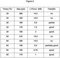
- the table in Figure 6 shows five experiments at a temperature of 25°C with decreasing gap widths of 200 ⁇ m, 190 ⁇ m, 180 ⁇ m, 170 ⁇ m and 160 ⁇ m.
- the selected temperature and gap widths led to increasing L-forces of ⁇ 0.2 kN, ⁇ 0.5 kN, 0.5 kN, 1.5 kN and 2 kN, respectively.
- lower gap widths are associated with higher pressures.
- the column under the heading "Transfer” in Figure 6 evaluates the transfer of lithium to the anode material. There was no transfer at L-forces of ⁇ 0.2 kN or ⁇ 0.5 kN. There was a partial transfer at an L-force of 0.5 kN. There was a good transfer at L-forces of 1.5 and 2 kN (not according to the invention unless embraced by the claims).
- the table in Figure 6 further shows five experiments at a temperature of 25°C with decreasing gap widths of 210 ⁇ m, 200 ⁇ m, 190 ⁇ m, 180 ⁇ m, and 170 ⁇ m.
- the selected temperature and gap widths led to L-forces of ⁇ 0.2 kN, ⁇ 0.5 kN, 0.5 kN, 0.75 kN and 1 kN, respectively.
- There was a good transfer at L-forces of 0.75 and 1 kN (not according to the invention unless embraced by the claims).
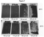
- a good transfer of lithium to the anode material is characterized by a high level of homogeneity in the application of lithium, as can be taken from Figure 7 .
- the pictures in Figure 7 reveal that the application is homogeneous for experiments conducted at 25°C with 160 or 170 ⁇ m slit (i.e. gap width) or at 65°C with 170 or 180 ⁇ m slit (not according to the invention unless embraced by the claims).
- the experiments demonstrate that the higher the temperature, the lower the pressure required for good transfer.
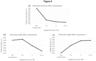
- Figure 8 shows effects of applied pressure on the deviation of thickness, width and length of the electrode at room temperature.
- the first graph shows the electrode compression in terms of thickness deviation in %.
- the second graph shows the electrode width in terms of width deviation in %.
- the third graph shows the electrode length in terms of length deviation in %.
- the pressure can be further reduced by applying the lithium foil at higher temperatures. This reduces the deformation of the electrode, which does not change the properties of the electrode despite pre-lithiation.
- the pre-lithiated anode sheet obtained in step 5 of Figure 3 is preferably stored for no more than 3 hours before cutting according to step 7 of Figure 4 (see below) at a temperature in the range from 5 to 20°C, preferably from 5 to 10°C.
- the storage time of no more than 3 hours is calculated from step 4 of Figure 3 .
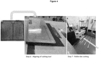
- Figure 4 shows the aligning of a cutting tool to the pre-lithiated anode sheet of Figure 3 (step 6) and the subsequent roller-die-cutting (step 7).
- the step of cutting is not limited to roller-die-cutting and can be effected by any other suitable cutting technique.
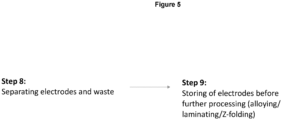
- Figure 5 shows the step of separating electrodes and waste (step 8) and the step of storing the electrodes before further processing (such as alloying/laminating/Z-folding) (step 9).
- the alloying time in a step of alloying the electrode is generally in the range from 12 to 72 hours and is preferably in the range from 18 to 28 hours.
- the alloying temperature can be in the range from 20 to 60°C and is preferably at about room temperature, as more side reactions occur with higher temperatures.
- the alloying atmosphere can be a dry room (having a dew point of about -50°C) or a CO 2 atmosphere.
- the alloying atmosphere should not be any of argon (Ar), nitrogen (N 2 ) or vaccum, as such an atmosphere would entail too many side reactions.
- the present inventors have surprisingly found a method of fabricating a pre-lithiated electrode that is industrially applicable, allowing an efficient homogeneous transfer of lithium to an anode material without compressing the anode material or leading to any decomposition reaction on the anode.
- the pre-lithiated electrode can be used as part of a high performance lithium-ion battery cell, which requires high electric current and high energy density.
Landscapes
- Chemical & Material Sciences (AREA)
- Engineering & Computer Science (AREA)
- Chemical Kinetics & Catalysis (AREA)
- Electrochemistry (AREA)
- General Chemical & Material Sciences (AREA)
- Materials Engineering (AREA)
- Manufacturing & Machinery (AREA)
- Inorganic Chemistry (AREA)
- Battery Electrode And Active Subsutance (AREA)
Description
- The present invention is directed to a method of fabricating a pre-lithiated electrode and a lithium-ion battery cell comprising said pre-lithiated electrode.
- Lithium (Li) ion batteries have played a role in the development of current generation mobile devices, microelectronics and electric vehicles. A typical Li-ion battery is made of a positive electrode (cathode), a negative electrode (anode), an electrolyte to conduct ions, a porous separator membrane, which is generally an electrical insulator, between the two electrodes to keep them physically apart, and a surrounding packaging.
- The rapid advancement and complex requirements of the energy storage industry requires lithium-ion batteries with improved energy density and cycle life. The improved energy density can be achieved with anodes containing silicon or silicon oxide. The drawback of this material is a higher demand of lithium leading to reduced cycle life, i.e. less cyclable lithium. Reduced cyclable lithium results in a reduced usable cell capacity. The addition of lithium during lithium-ion battery production, known as pre-lithiation, is used to compensate for these lithium losses.
- Various anode pre-lithiation methods exist including chemical pre-lithiation, electrochemical pre-lithiation, and stabilized lithium metal powder.
-
US 2022/0052307 A1 discloses an in-line contact pre-lithiation. Further, the application of thin lithium foil for direct contact pre-lithiation of anodes within lithium ion battery production is disclosed by Benedikt Stumper et al., Procedia CIRP 93(2020), 156-161. - The problem underlying the present invention is to provide an improved method for fabricating a pre-lithiated electrode and a lithium-ion battery cell comprising said pre-lithiated electrode, said method being industrially applicable and allowing efficient and homogeneous transfer of lithium to the electrode without compromising the quality of the electrode.
- The subject matter of the invention is as set out in the appended claims.
- One aspect of the invention relates to a method of fabricating a pre-lithiated electrode, comprising:
- disposing a Li-PET sheet comprising a layer of lithium metal adjacent to a prefabricated electrode comprising a layer of anode material;
- contacting a surface of the layer of anode material with a surface of the layer of lithium metal; and
- calendering the layer of lithium metal and the prefabricated electrode together,
- said calendering comprising transferring the layer of lithium metal and the prefabricated electrode through a pair of calendering rolls,
- said calendering further comprising applying uniform pressure to a back surface of the PET-sheet, wherein the uniform pressure is a pressure ranging from about 0.7 kN to about 0.8 kN,
- wherein the front roll and/or the back roll is heated to a temperature in the range of from about 40°C to about 75°C, and
- PET denotes polyethylene terephthalate or a derivative of polyethylene terephthalate.
- A further aspect of the invention relates to a lithium-ion battery cell, comprising:
- a pre-lithiated electrode formed according to the method according to the invention;
- a positive electrode comprising oxides of a transition metal; and
- an electrolyte, wherein the electrolyte is selected from a solid electrolyte, a liquid electrolyte, or a polymer electrolyte.
- Preferred embodiments are set forth in the dependent claims.
- In a preferred embodiment in combination with any of the above or below embodiments, said method further comprises separating the PET sheet from the surface of the layer of anode material to form the pre-lithiated electrode.
- In a further preferred embodiment in combination with any of the above or below embodiments, the PET layer has a thickness of about 20 µm to about 200 µm, more preferably of about 30 µm to 80 µm, in particular about 50 µm.
- In a further preferred embodiment in combination with any of the above or below embodiments, the PET layer further comprises a release layer.
- In a further preferred embodiment in combination with any of the above or below embodiments, said release layer has a thickness of about 0.005 µm to about 2 µm.
- In a further preferred embodiment in combination with any of the above or below embodiments, calendering the layer of lithium metal comprises applying uniform pressure to a back surface of the carrier substrate, wherein the uniform pressure is a pressure ranging from about 1.9 MPa to about 8.9 MPa, preferably from about 3.2 MPa to about 5.3 MPa (not according to the invention unless embraced by the claims).
- Calendering the layer of lithium metal and the prefabricated electrode together comprises transferring the layer of lithium metal and the prefabricated electrode through a pair of calendering rolls.
- In a further preferred embodiment in combination with any of the above or below embodiments, the method further comprises heating the front roll to a temperature in the range of from about 40°C to about 75°C, more preferably from about 60°C to about 70°C, in particular about 65°C.
- In a further preferred embodiment in combination with any of the above or below embodiments, the method further comprises heating the back roll to a temperature in the range of from about 40°C to about 75°C, more preferably from about 60°C to about 70°C, in particular about 65°C.
- In a further preferred embodiment in combination with any of the above or below embodiments, the prefabricated electrode is a negative electrode comprising a Cu carrier foil.
- In a further preferred embodiment in combination with any of the above or below embodiments, said Cu carrier foil has a thickness of about 6 µm to about 12 µm, in particular about 8 µm.
- In a further preferred embodiment in combination with any of the above or below embodiments, the prefabricated electrode is a negative electrode comprising a carbonaceous material, silicon, silicon oxide or combinations thereof.
- In a further preferred embodiment in combination with any of the above or below embodiments, the carbonaceous material is selected from natural graphite, artificial graphite, or combinations thereof.
- In a further preferred embodiment in combination with any of the above or below embodiments, the prefabricated electrode is a negative electrode having a coating, said coating preferably comprising SiOyCz, wherein y is from 0 to 2 and z is 0 or 1.
- In a further preferred embodiment in combination with any of the above or below embodiments, the coating is a double-sided coating.
- In a further preferred embodiment in combination with any of the above or below embodiments, the coating has a thickness of about 10 µm to about 80 µm.
- In a further preferred embodiment in combination with any of the above or below embodiments, the layer of lithium metal has a thickness from about 3 µm to about 15 µm, more preferably from about 6 µm to about 12 µm, in particular about 9.3 µm. The lithium layer needs to be passivated, preferably by CO2.
- In a further preferred embodiment in combination with any of the above or below embodiments, the gap between the calendering rolls is from about 160 µm to about 200 µm, preferably from about 170 µm to about 190 µm, more preferably about 180 µm.
- Alternatively, the pressure applied to the back surface of the carrier substrate can be defined in kN. Calendering the layer of lithium metal comprises applying uniform pressure to a back surface of the carrier substrate, wherein the uniform pressure is a pressure ranging from about 0.7 kN to about 0.8 kN, preferably about 0.75 kN.
- In a further preferred embodiment in combination with any of the above or below embodiments, the method further comprises incorporating the pre-lithiated electrode into an electrochemical cell further comprising a positive electrode, a separator, and an electrolyte.
- A further aspect of the invention relates to a lithium-ion battery cell, comprising:
- a pre-lithiated electrode formed according to the method according to the invention;
- a positive electrode comprising oxides of a metal, preferably a transition metal; and
- an electrolyte, wherein the electrolyte is selected from a solid electrolyte, a liquid electrolyte, or a polymer electrolyte.
- In a further preferred embodiment in combination with any of the above or below embodiments, each of the pre-lithiated electrode and the positive electrode are in a fully charged position.
- In a further preferred embodiment in combination with any of the above or below embodiments, each of the pre-lithiated electrode and the positive electrode are in a partially charged position.
- In a further preferred embodiment in combination with any of the above or below embodiments, the pre-lithiated electrode is completely lithiated in the fully charged position and the positive electrode is completely delithiated in the fully charged position.
- The present specification is not limited to the use of a Li-PET sheet, although only the use of a Li-PET sheet is embraced by the claims. In more general terms, the present specification therefore discloses a method of fabricating a pre-lithiated electrode, comprising:
- disposing a carrier substrate comprising a layer of lithium metal adjacent to a prefabricated electrode comprising a layer of anode material;
- contacting a surface of the layer of anode material with a surface of the layer of lithium metal; and
- calendering the layer of lithium metal and the prefabricated electrode together.
- In a preferred embodiment in combination with any of the above or below embodiments, the carrier substrate is a PET substrate.
- In a further preferred embodiment in combination with any of the above or below embodiments, the carrier substrate is a sheet. The preferred embodiments set out above for claimed method including the use of a Li-PET sheet are also applicable to the method including the use of a carrier substrate.
- In a preferred embodiment in combination with any of the above or below embodiments, the method is implemented as a roll-to-roll process. The term "sheet" as used herein is intended to designate a flexible material to which lithium is applied. The term is not limited to a specific geometrical shape, such as a layer, but also includes material that is wound into a roll.
-
-
Figure 1 illustrates a material flow according to an aspect of the present invention. -
Figure 2 depictssteps 1 to 3 of 9 of the pre-lithiation procedure according to an aspect of the present invention. -
Figure 3 depictssteps -
Figure 4 depictssteps -
Figure 5 depictssteps -
Figure 6 depicts the adjustment of pressure/temperature instep 4 of the pre-lithiation procedure according to an aspect of the present invention. -
Figure 7 depicts pictures relating to table inFigure 6 showing different levels of homogeneity in application of lithium. -
Figure 8 shows effects of applied pressure on the deviation of thickness, width and length of the electrode at room temperature. Commas within numeral labels inFigure 8 should be interpreted as decimal points. - The following describes the claimed method of fabricating a pre-lithiated electrode and the claimed lithium-ion battery cell.
- Certain details are set forth in the following description and in the Figures to provide a thorough understanding of various implementations of the invention. Other details describing well-known structures and systems often associated with electrochemical cells and batteries are not set forth in the following to avoid unnecessarily obscuring the description of the various implementations.
- Many of the details, dimensions, angles and other features shown in the Figures are merely illustrative of particular implementations. Accordingly, other implementations can have other details, components, dimensions, angles and features without departing from the scope of the present invention.
- As used herein, each of the terms "comprising', "having" and "containing", including grammatical variants thereof, are meant in a non-exhaustive sense to mean "including", but not necessarily "composed of", and does not exclude elements in addition to those explicitly recited as being present. As used herein, then, the terms "comprising", "having" and "containing", and grammatical variants thereof, indicate that components other than those explicitly recited may, but need not, be present. As such these terms include as a limiting case embodiments in which no other elements than those recited are present, e.g. in the commonly accepted sense of "consisting of".
- As used herein, the phrase "consisting of", and grammatically related variants thereof, means that no other elements are present in those recited. In standing with the above definition of "comprising" (and grammatically and semantically related terms), the term "consisting of" therefore denotes a limiting scenario within the meaning of "comprising".
- As used herein, the term "PET" denotes the known polymeric material polyethylene terephthalate. The term "PET" also includes a derivative of PET.
- In more general terms, the PET or the derivative of PET can be replaced by a carrier substrate, provided that the carrier substrate is flexible and ensures the adhesion of the lithium layer and its release under pressure, ensures the adhesion of the release layer, is chemically inert with respect to the release layer and lithium, and is stable under pressure in the selected pressure range.
- Unless defined otherwise, any feature within any aspect or embodiment of the invention may be combined with any feature within any other aspect or embodiment of the invention, and the skilled person understands such combination as being encompassed in the original disclosure of the present application. This applies in particular to all embodiments described within the section relating to the method of fabricating a pre-lithiated electrode per se, in respect of other aspects, e.g. the lithium-ion battery cell. This also applies in particular, but not exclusively, to endpoints of ranges disclosed herein.
- As used herein the term "about" when referring to a particular value, e.g. an endpoint or endpoints of a range, encompasses and discloses, in addition to the specifically recited value itself, a certain variation around the specifically recited value. Such a variation may for example arise from normal measurement variability. The term "about" shall be understood as encompassing and disclosing a range of variability above and below an indicated specific value, said percentage values being relative to the specific recited value itself, as follows. The term "about" may denote variability of ± 5.0%. The term "about" may denote variability of ± 4.0%. The term "about" may denote variability of ± 3.0%. The term "about" may denote variability of ± 2.0%. The term "about" may denote variability of ± 1.0%. The term "about", in reference to the particular recited value, may denote that exact particular value itself, irrespective of any explicit mention that this exact particular value is included; even in the absence of an explicit indication that the term "about" includes the particular exact recited value, this exact particular value is still included in the range of variation created by the term "about", and is therefore disclosed.
- Implementations described herein will be described below in reference to a roll-to-roll coating system. It should also be understood that although described as a roll-to-roll process, the implementations described herein can be performed on discrete substrates.
- The pre-lithiation method described herein is applicable to Li-ion batteries using solid electrolytes (e.g., solid-state batteries) as well as Li-ion batteries, which use liquid or polymer electrolytes.
- The claimed method involves the pre-lithiation of anode materials with a lithium coated substrate, preferably PET, by way of direct contact. Direct contact is an effective way to pre-lithiate the anode material as this creates excellent surface contact between the lithium and the anode layer. The method described herein can be slotted into current battery production lines.
- The carrier substrate for lithium, preferably PET, is a flexible substrate, which can be used in roll-to-roll coating.
- The calender rolls must be about 100% cylindrical to ensure uniform pressure distribution. Uniform pressure distribution means a pressure distribution on the surface of no more than +/-5%. The front roll is the roll that points to the subsequent process and the back roll is the roll that points away from the subsequent process.
- In a roll-to-roll process, roll is defined as coiled strip material. During the process run, the unwound material is in the process as a strip and can then be separated directly into electrodes or rewound as a roll. This roll can have a cyclindrical or substantially cyclindrical shape.
-
Figures 1 illustrates a material flow according to the invention. This material flow is further illustrated by pictures inFigures 2 to 5 . The material flow inFigure 1 can be correlated to the pictures inFigures 2 to 5 as follows: - Step (1) in
Figure 1 showssteps 1 to 4 inFigures 2 and3 in condensed form; - Step (2) in
Figure 1 corresponds to step 5 inFigure 3 ; - Step (3) in
Figure 1 showssteps Figure 4 in condensed form; and - Step (4) in
Figure 1 showssteps Figure 5 in condensed form. - As shown in
Figure 1 , the Li-PET sheet is pressed to an anode, which is preferably a Cu carrier foil having a double-sided coating containing SiOyCz, wherein y is 0-2 and z is 0 or 1.Figure 1 shows - (1) Contacting the three layers with a certain pressure and temperature,
- (2) Removing the carrier foil,
- (3) Cutting out electrodes, and
- (4) Alloying the electrodes.
- The steps (1) and (4) of
Figure 1 must be adjusted to achieve the following goals: - The carrier PET foil can be removed according to step (2) of
Figure 1 while ensuring a homogeneous transfer of lithium to the anode; - The applied pressure in step (1) of
Figure 1 does not lead to- ∘ A compression of the anode material itself, or
- ∘ A deformation of the PET foil;
- The applied temperature in step (1) does not lead to any decomposition reaction on the anode;
- The step (4) of alloying the electrodes is slow enough to be of no risk for the production, to be homogeneous and to allow the cutting of the electrode before the material gets brittle; and
- The step (4) of alloying the electrodes is fast enough to remove elemental lithium from the anode surface to allow the follow up processing of the electrode (laminating).
-
Figures 2 to 5 further illustrate the material flow according toFigure 1 as described above. -
Figure 2 show the provision of a first Li-PET sheet (step 1), the aligning of an anode on top of said first Li-PET sheet (step 2), and the aligning of a second Li-PET sheet on top of the anode to achieve a three-layered structure of Li-PET sheet/anode/Li-PET sheet (step 3). -
Figure 3 shows the calendering of the three-layered structure of Li-PET sheet/anode/Li-PET sheet ofFigure 2 (step 4) and the removal of the carrier substrate (PET) to obtain a pre-lithiated anode sheet (step 5). - The calendering of the three-layered structure of Li-PET sheet/anode/Li-PET sheet according to
step 4 is preferably carried out with a front roll having a temperature in the range of from about 40°C to about 75°C, more preferably from about 60°C to about 70°C, and in particular about 65°C, and a back roll having preferably a temperature in the range of from about 40°C to about 75°C, more preferably from about 60°C to about 70°C, and in particular about 65°C. A homogeneous transfer of lithium can, however, also be achieved at room temperature, as discussed below. The friction between the calendering rolls can be within the range of about +/- 2%. The sheet is preferably processed through the calendering rolls at a speed that ensures a homogeneous temperature of +/- 2 °C. The sheet is therefore preferably processed at a speed of about 0.1-5 m/min, more preferably at a speed of about 2 m/min. Alternatively or in addition, the sheet may be pre-heated.Step 4 further preferably comprises applying uniform pressure to a back surface of the carrier substrate, wherein the uniform pressure is a pressure ranging from about 1.9 MPa to about 8.9 MPa, preferably from about 3.2 MPa to about 5.3 MPa (not according to the invention unless embraced by the claims). The gap between the calendering rolls instep 4 is preferably from about 160 µm to about 200 µm, more preferably from about 170 µm to about 190 µm, and in particular about 180 µm. - The technical effect of the different parameters temperature, gap and pressure, and their interrelation is further illustrated in
Figure 6 . The experiments shown inFigure 6 aim to achieve complete lithium transfer while keeping the line force as low as possible to avoid any potential damage to the anode material itself, e.g., loss of porosity and thus performance, and to avoid a deformation of the PET foil. It should be understood that the temperature and the gap determine the pressure (expressed as L-force (kN) inFigure 6 ). - The table in
Figure 6 shows five experiments at a temperature of 25°C with decreasing gap widths of 200 µm, 190 µm, 180 µm, 170 µm and 160 µm. The selected temperature and gap widths led to increasing L-forces of < 0.2 kN, < 0.5 kN, 0.5 kN, 1.5 kN and 2 kN, respectively. Thus, lower gap widths are associated with higher pressures. The column under the heading "Transfer" inFigure 6 evaluates the transfer of lithium to the anode material. There was no transfer at L-forces of < 0.2 kN or < 0.5 kN. There was a partial transfer at an L-force of 0.5 kN. There was a good transfer at L-forces of 1.5 and 2 kN (not according to the invention unless embraced by the claims). - The table in
Figure 6 further shows five experiments at a temperature of 25°C with decreasing gap widths of 210 µm, 200 µm, 190 µm, 180 µm, and 170 µm. The selected temperature and gap widths led to L-forces of < 0.2 kN, < 0.5 kN, 0.5 kN, 0.75 kN and 1 kN, respectively. There was no transfer at L-forces of < 0.2 kN or < 0.5 kN. There was a partial transfer at an L-force of 0.5 kN. There was a good transfer at L-forces of 0.75 and 1 kN (not according to the invention unless embraced by the claims). - A good transfer of lithium to the anode material is characterized by a high level of homogeneity in the application of lithium, as can be taken from
Figure 7 . The pictures inFigure 7 reveal that the application is homogeneous for experiments conducted at 25°C with 160 or 170 µm slit (i.e. gap width) or at 65°C with 170 or 180 µm slit (not according to the invention unless embraced by the claims). The experiments demonstrate that the higher the temperature, the lower the pressure required for good transfer. - The experiments shown in
Figures 6 and7 were also carried out at temperatures of 40°C, 70°C, and 80°C. 80°C yielded no transfer at all for the applied gaps and the results at 70°C were not as good as the results at 65°C. Further, the results at 40°C lay between the results at 25°C and at 65°C. - The data in the table of
Figure 6 thus reveals a trend, i.e. the higher the temperature, the lower the pressure needed for good lithium transfer. While four experiments were evaluated to achieve "good" transfer of lithium, such "good" transfer can be achieved e.g. by applying an L-force of only about 0.75 kN at a temperature of about 65°C. This a surprisingly good result. Both a higher temperature of 70°C and a lower temperature of 40°C led to less desirable results, as described above. -
Figure 8 shows effects of applied pressure on the deviation of thickness, width and length of the electrode at room temperature. - The first graph shows the electrode compression in terms of thickness deviation in %.
- The second graph shows the electrode width in terms of width deviation in %.
- The third graph shows the electrode length in terms of length deviation in %.
- As shown in
Figure 8 , the effect of compression on the length, width and thickness of the electrode at room temperature is exemplified. The aim is to change the electrode as little as possible. It was found that the width of the electrode remains unchanged by compression up to a pressure of 1.5 kN and then decreases, i.e. is constricted. The length and thickness of the electrode change proportionally to the contact pressure. Therefore, it could be determined that a contact pressure of 1.5 kN causes the fewest geometric changes on the electrode. - As shown in
Figure 6 , the pressure can be further reduced by applying the lithium foil at higher temperatures. This reduces the deformation of the electrode, which does not change the properties of the electrode despite pre-lithiation. - Thus, an optimal combination of temperature and pressure respectively gap of the calendering rolls was found to achieve a pre-lithiation process reducing the anode compression, ensuring good application of the lithium foil.
- The pre-lithiated anode sheet obtained in
step 5 ofFigure 3 is preferably stored for no more than 3 hours before cutting according tostep 7 ofFigure 4 (see below) at a temperature in the range from 5 to 20°C, preferably from 5 to 10°C. The storage time of no more than 3 hours is calculated fromstep 4 ofFigure 3 . -
Figure 4 shows the aligning of a cutting tool to the pre-lithiated anode sheet ofFigure 3 (step 6) and the subsequent roller-die-cutting (step 7). The step of cutting is not limited to roller-die-cutting and can be effected by any other suitable cutting technique. -
Figure 5 shows the step of separating electrodes and waste (step 8) and the step of storing the electrodes before further processing (such as alloying/laminating/Z-folding) (step 9). - The alloying time in a step of alloying the electrode is generally in the range from 12 to 72 hours and is preferably in the range from 18 to 28 hours. The alloying temperature can be in the range from 20 to 60°C and is preferably at about room temperature, as more side reactions occur with higher temperatures. The alloying atmosphere can be a dry room (having a dew point of about -50°C) or a CO2 atmosphere. The alloying atmosphere should not be any of argon (Ar), nitrogen (N2) or vaccum, as such an atmosphere would entail too many side reactions.
- Summarizing the above, the present inventors have surprisingly found a method of fabricating a pre-lithiated electrode that is industrially applicable, allowing an efficient homogeneous transfer of lithium to an anode material without compressing the anode material or leading to any decomposition reaction on the anode. The pre-lithiated electrode can be used as part of a high performance lithium-ion battery cell, which requires high electric current and high energy density.
Claims (13)
- A method of fabricating a pre-lithiated electrode, comprising:disposing a Li-PET sheet comprising a layer of lithium metal adjacent to a prefabricated electrode comprising a layer of anode material;contacting a surface of the layer of anode material with a surface of the layer of lithium metal; andcalendering the layer of lithium metal and the prefabricated electrode together,said calendering comprising transferring the layer of lithium metal and the prefabricated electrode through a pair of calendering rolls,said calendering further comprising applying uniform pressure to a back surface of the PET-sheet, wherein the uniform pressure is a pressure ranging from about 0.7 kN to about 0.8 kN,wherein the front roll and/or the back roll is heated to a temperature in the range of from about 40°C to about 75°C, andPET denotes polyethylene terephthalate or a derivative of polyethylene terephthalate.
- The method according to claim 1, further comprising:
separating the PET sheet from the surface of the layer of anode material to form the pre-lithiated electrode, wherein the PET layer preferably has a thickness of about 20 µm to about 200 µm. - The method according to claim 1 or claim 2, wherein the PET layer further comprises a release layer, said release layer preferably having a thickness of about 0.005 µm to about 1 µm.
- The method according to any one of claims 1 to 3, further comprising heating the front roll to a temperature in the range of from about 40°C to about 75°C, preferably from about 60°C to about 70°C, in particular about 65°C.
- The method according to any one of claims 1 to 4, further comprising heating the back roll to a temperature in the range of from about 40°C to about 75°C, preferably from about 60°C to about 70°C, in particular about 65°C.
- The method according to any one of claims 1 to 5, wherein the prefabricated electrode is a negative electrode comprising a Cu carrier foil, said Cu carrier foil preferably having a thickness of about 6 µm to about 12 µm.
- The method according to any one of claims 1 to 6, wherein the prefabricated electrode is a negative electrode comprising a carbonaceous material, silicon, silicon oxide or combinations thereof, said carbonaceous material preferably being selected from natural graphite, artificial graphite, or combinations thereof.
- The method according to any one of claims 1 to 7, wherein the prefabricated electrode is a negative electrode having a coating, said coating preferably comprising SiOyCz, wherein y is from 0 to 2 and z is 0 or 1.
- The method according to claim 8, wherein the coating is a double-sided coating and/or has a thickness of about 10 µm to about 80 µm.
- The method according to any one of claims 1 to 9, wherein the gap between the calendering rolls is from about 160 µm to about 200 µm, preferably from about 170 µm to about 190 µm, more preferably about 180 µm.
- The method according to any one of claims 1 to 10, further comprising incorporating the pre-lithiated electrode into an electrochemical cell further comprising a positive electrode, a separator, and an electrolyte.
- A lithium-ion battery cell, comprising:a pre-lithiated electrode formed according to the method according to any one of claims 1 to 11;a positive electrode comprising oxides of a transition metal; andan electrolyte, wherein the electrolyte is selected from a solid electrolyte, a liquid electrolyte, or a polymer electrolyte.
- The lithium-ion battery cell according to claim 12, wherein each of the pre-lithiated electrode and the positive electrode are in a fully charged position, preferably wherein the pre-lithiated electrode is completely lithiated in the fully charged position and the positive electrode is completely delithiated in the fully charged position.
Priority Applications (4)
| Application Number | Priority Date | Filing Date | Title |
|---|---|---|---|
| EP22208678.7A EP4372833B1 (en) | 2022-11-21 | 2022-11-21 | Method of fabricating a pre-lithiated electrode and lithium-ion battery cell |
| CN202311408433.6A CN118057633A (en) | 2022-11-21 | 2023-10-26 | Method for manufacturing pre-lithiation electrode and lithium-ion battery cell |
| US18/494,985 US20240170643A1 (en) | 2022-11-21 | 2023-10-26 | Method of fabricating a pre-lithiated electrode and lithium-ion battery cell |
| PCT/EP2023/079946 WO2024110147A1 (en) | 2022-11-21 | 2023-10-26 | Method of fabricating a pre-lithiated electrode and lithium-ion battery cell |
Applications Claiming Priority (1)
| Application Number | Priority Date | Filing Date | Title |
|---|---|---|---|
| EP22208678.7A EP4372833B1 (en) | 2022-11-21 | 2022-11-21 | Method of fabricating a pre-lithiated electrode and lithium-ion battery cell |
Publications (2)
| Publication Number | Publication Date |
|---|---|
| EP4372833A1 EP4372833A1 (en) | 2024-05-22 |
| EP4372833B1 true EP4372833B1 (en) | 2024-10-30 |
Family
ID=84361046
Family Applications (1)
| Application Number | Title | Priority Date | Filing Date |
|---|---|---|---|
| EP22208678.7A Active EP4372833B1 (en) | 2022-11-21 | 2022-11-21 | Method of fabricating a pre-lithiated electrode and lithium-ion battery cell |
Country Status (4)
| Country | Link |
|---|---|
| US (1) | US20240170643A1 (en) |
| EP (1) | EP4372833B1 (en) |
| CN (1) | CN118057633A (en) |
| WO (1) | WO2024110147A1 (en) |
Family Cites Families (2)
| Publication number | Priority date | Publication date | Assignee | Title |
|---|---|---|---|---|
| WO2021253318A1 (en) * | 2020-06-18 | 2021-12-23 | 天津中能锂业有限公司 | Ultrathin lithium bar preform, composite negative electrode, manufacturing method therefor, and battery |
| JP2023537922A (en) | 2020-08-11 | 2023-09-06 | アプライド マテリアルズ インコーポレイテッド | In-line contact prelithiation |
-
2022
- 2022-11-21 EP EP22208678.7A patent/EP4372833B1/en active Active
-
2023
- 2023-10-26 US US18/494,985 patent/US20240170643A1/en active Pending
- 2023-10-26 WO PCT/EP2023/079946 patent/WO2024110147A1/en not_active Ceased
- 2023-10-26 CN CN202311408433.6A patent/CN118057633A/en active Pending
Also Published As
| Publication number | Publication date |
|---|---|
| EP4372833A1 (en) | 2024-05-22 |
| CN118057633A (en) | 2024-05-21 |
| US20240170643A1 (en) | 2024-05-23 |
| WO2024110147A1 (en) | 2024-05-30 |
Similar Documents
| Publication | Publication Date | Title |
|---|---|---|
| JP7417642B2 (en) | Lithium deposition using integrated protective layer tools | |
| KR102162773B1 (en) | Method for Manufacturing Electrode for Secondary Battery Comprising Pre-Slitting Process | |
| EP2815447B1 (en) | Reinforced metal foil electrode | |
| EP2006942A2 (en) | Secondary battery, manufacturing method thereof and system thereof | |
| US20060006063A1 (en) | Method of manufacturing electrode and electrode | |
| US20200083506A1 (en) | Ceramic coating on separator for batteries | |
| TW202213840A (en) | Inline contact pre-lithiation | |
| JP4831946B2 (en) | Non-aqueous electrolyte battery | |
| Stumper et al. | Application of thin lithium foil for direct contact prelithiation of anodes within lithium-ion battery production | |
| KR102264657B1 (en) | Pressing Apparatus for Electrode Sheet Having Guide Roller | |
| US20240021776A1 (en) | Method of manufacturing an anode structure, vacuum deposition system, anode structure, and lithium battery layer stack | |
| KR102124822B1 (en) | Electrode Workpiece Comprising Electrode Tab Having Knurling Portion and Device for Manufacturing the Same | |
| EP3598555B1 (en) | Electrode, electrode assembly and method for manufacturing the same | |
| CN216928627U (en) | Lithium-copper composite belt, lithium-copper composite negative electrode and battery | |
| EP4372833B1 (en) | Method of fabricating a pre-lithiated electrode and lithium-ion battery cell | |
| KR20190113628A (en) | Rolled copper foil for lithium ion battery collectors and lithium ion battery | |
| KR20240090091A (en) | Electrode manufacturing apparatus and method | |
| KR20260054369A (en) | Pressing apparatus for electrode sheet |
Legal Events
| Date | Code | Title | Description |
|---|---|---|---|
| PUAI | Public reference made under article 153(3) epc to a published international application that has entered the european phase |
Free format text: ORIGINAL CODE: 0009012 |
|
| STAA | Information on the status of an ep patent application or granted ep patent |
Free format text: STATUS: REQUEST FOR EXAMINATION WAS MADE |
|
| 17P | Request for examination filed |
Effective date: 20231215 |
|
| AK | Designated contracting states |
Kind code of ref document: A1 Designated state(s): AL AT BE BG CH CY CZ DE DK EE ES FI FR GB GR HR HU IE IS IT LI LT LU LV MC ME MK MT NL NO PL PT RO RS SE SI SK SM TR |
|
| GRAP | Despatch of communication of intention to grant a patent |
Free format text: ORIGINAL CODE: EPIDOSNIGR1 |
|
| STAA | Information on the status of an ep patent application or granted ep patent |
Free format text: STATUS: GRANT OF PATENT IS INTENDED |
|
| INTG | Intention to grant announced |
Effective date: 20240620 |
|
| GRAS | Grant fee paid |
Free format text: ORIGINAL CODE: EPIDOSNIGR3 |
|
| P01 | Opt-out of the competence of the unified patent court (upc) registered |
Free format text: CASE NUMBER: APP_47732/2024 Effective date: 20240820 |
|
| GRAA | (expected) grant |
Free format text: ORIGINAL CODE: 0009210 |
|
| STAA | Information on the status of an ep patent application or granted ep patent |
Free format text: STATUS: THE PATENT HAS BEEN GRANTED |
|
| AK | Designated contracting states |
Kind code of ref document: B1 Designated state(s): AL AT BE BG CH CY CZ DE DK EE ES FI FR GB GR HR HU IE IS IT LI LT LU LV MC ME MK MT NL NO PL PT RO RS SE SI SK SM TR |
|
| REG | Reference to a national code |
Ref country code: GB Ref legal event code: FG4D |
|
| REG | Reference to a national code |
Ref country code: CH Ref legal event code: EP |
|
| REG | Reference to a national code |
Ref country code: IE Ref legal event code: FG4D |
|
| REG | Reference to a national code |
Ref country code: DE Ref legal event code: R096 Ref document number: 602022007238 Country of ref document: DE |
|
| REG | Reference to a national code |
Ref country code: LT Ref legal event code: MG9D |
|
| REG | Reference to a national code |
Ref country code: NL Ref legal event code: MP Effective date: 20241030 |
|
| PG25 | Lapsed in a contracting state [announced via postgrant information from national office to epo] |
Ref country code: HR Free format text: LAPSE BECAUSE OF FAILURE TO SUBMIT A TRANSLATION OF THE DESCRIPTION OR TO PAY THE FEE WITHIN THE PRESCRIBED TIME-LIMIT Effective date: 20241030 Ref country code: PT Free format text: LAPSE BECAUSE OF FAILURE TO SUBMIT A TRANSLATION OF THE DESCRIPTION OR TO PAY THE FEE WITHIN THE PRESCRIBED TIME-LIMIT Effective date: 20250228 Ref country code: IS Free format text: LAPSE BECAUSE OF FAILURE TO SUBMIT A TRANSLATION OF THE DESCRIPTION OR TO PAY THE FEE WITHIN THE PRESCRIBED TIME-LIMIT Effective date: 20250228 |
|
| PG25 | Lapsed in a contracting state [announced via postgrant information from national office to epo] |
Ref country code: FI Free format text: LAPSE BECAUSE OF FAILURE TO SUBMIT A TRANSLATION OF THE DESCRIPTION OR TO PAY THE FEE WITHIN THE PRESCRIBED TIME-LIMIT Effective date: 20241030 Ref country code: NL Free format text: LAPSE BECAUSE OF FAILURE TO SUBMIT A TRANSLATION OF THE DESCRIPTION OR TO PAY THE FEE WITHIN THE PRESCRIBED TIME-LIMIT Effective date: 20241030 |
|
| REG | Reference to a national code |
Ref country code: AT Ref legal event code: MK05 Ref document number: 1737823 Country of ref document: AT Kind code of ref document: T Effective date: 20241030 |
|
| PG25 | Lapsed in a contracting state [announced via postgrant information from national office to epo] |
Ref country code: BG Free format text: LAPSE BECAUSE OF FAILURE TO SUBMIT A TRANSLATION OF THE DESCRIPTION OR TO PAY THE FEE WITHIN THE PRESCRIBED TIME-LIMIT Effective date: 20241030 |
|
| PG25 | Lapsed in a contracting state [announced via postgrant information from national office to epo] |
Ref country code: ES Free format text: LAPSE BECAUSE OF FAILURE TO SUBMIT A TRANSLATION OF THE DESCRIPTION OR TO PAY THE FEE WITHIN THE PRESCRIBED TIME-LIMIT Effective date: 20241030 |
|
| PG25 | Lapsed in a contracting state [announced via postgrant information from national office to epo] |
Ref country code: NO Free format text: LAPSE BECAUSE OF FAILURE TO SUBMIT A TRANSLATION OF THE DESCRIPTION OR TO PAY THE FEE WITHIN THE PRESCRIBED TIME-LIMIT Effective date: 20250130 |
|
| PG25 | Lapsed in a contracting state [announced via postgrant information from national office to epo] |
Ref country code: AT Free format text: LAPSE BECAUSE OF FAILURE TO SUBMIT A TRANSLATION OF THE DESCRIPTION OR TO PAY THE FEE WITHIN THE PRESCRIBED TIME-LIMIT Effective date: 20241030 Ref country code: LV Free format text: LAPSE BECAUSE OF FAILURE TO SUBMIT A TRANSLATION OF THE DESCRIPTION OR TO PAY THE FEE WITHIN THE PRESCRIBED TIME-LIMIT Effective date: 20241030 Ref country code: GR Free format text: LAPSE BECAUSE OF FAILURE TO SUBMIT A TRANSLATION OF THE DESCRIPTION OR TO PAY THE FEE WITHIN THE PRESCRIBED TIME-LIMIT Effective date: 20250131 |
|
| PG25 | Lapsed in a contracting state [announced via postgrant information from national office to epo] |
Ref country code: PL Free format text: LAPSE BECAUSE OF FAILURE TO SUBMIT A TRANSLATION OF THE DESCRIPTION OR TO PAY THE FEE WITHIN THE PRESCRIBED TIME-LIMIT Effective date: 20241030 |
|
| PG25 | Lapsed in a contracting state [announced via postgrant information from national office to epo] |
Ref country code: RS Free format text: LAPSE BECAUSE OF FAILURE TO SUBMIT A TRANSLATION OF THE DESCRIPTION OR TO PAY THE FEE WITHIN THE PRESCRIBED TIME-LIMIT Effective date: 20250130 |
|
| REG | Reference to a national code |
Ref country code: DE Ref legal event code: R082 Ref document number: 602022007238 Country of ref document: DE Representative=s name: TER MEER STEINMEISTER & PARTNER PATENTANWAELTE, DE Ref country code: DE Ref legal event code: R082 Ref document number: 602022007238 Country of ref document: DE Representative=s name: FINNEGAN, HENDERSON, FARABOW, GARRETT & DUNNER, DE |
|
| PG25 | Lapsed in a contracting state [announced via postgrant information from national office to epo] |
Ref country code: SM Free format text: LAPSE BECAUSE OF FAILURE TO SUBMIT A TRANSLATION OF THE DESCRIPTION OR TO PAY THE FEE WITHIN THE PRESCRIBED TIME-LIMIT Effective date: 20241030 |
|
| PG25 | Lapsed in a contracting state [announced via postgrant information from national office to epo] |
Ref country code: MC Free format text: LAPSE BECAUSE OF FAILURE TO SUBMIT A TRANSLATION OF THE DESCRIPTION OR TO PAY THE FEE WITHIN THE PRESCRIBED TIME-LIMIT Effective date: 20241030 |
|
| PG25 | Lapsed in a contracting state [announced via postgrant information from national office to epo] |
Ref country code: DK Free format text: LAPSE BECAUSE OF FAILURE TO SUBMIT A TRANSLATION OF THE DESCRIPTION OR TO PAY THE FEE WITHIN THE PRESCRIBED TIME-LIMIT Effective date: 20241030 |
|
| PG25 | Lapsed in a contracting state [announced via postgrant information from national office to epo] |
Ref country code: LU Free format text: LAPSE BECAUSE OF NON-PAYMENT OF DUE FEES Effective date: 20241121 |
|
| PG25 | Lapsed in a contracting state [announced via postgrant information from national office to epo] |
Ref country code: EE Free format text: LAPSE BECAUSE OF FAILURE TO SUBMIT A TRANSLATION OF THE DESCRIPTION OR TO PAY THE FEE WITHIN THE PRESCRIBED TIME-LIMIT Effective date: 20241030 |
|
| PG25 | Lapsed in a contracting state [announced via postgrant information from national office to epo] |
Ref country code: RO Free format text: LAPSE BECAUSE OF FAILURE TO SUBMIT A TRANSLATION OF THE DESCRIPTION OR TO PAY THE FEE WITHIN THE PRESCRIBED TIME-LIMIT Effective date: 20241030 |
|
| PG25 | Lapsed in a contracting state [announced via postgrant information from national office to epo] |
Ref country code: SK Free format text: LAPSE BECAUSE OF FAILURE TO SUBMIT A TRANSLATION OF THE DESCRIPTION OR TO PAY THE FEE WITHIN THE PRESCRIBED TIME-LIMIT Effective date: 20241030 |
|
| PG25 | Lapsed in a contracting state [announced via postgrant information from national office to epo] |
Ref country code: CZ Free format text: LAPSE BECAUSE OF FAILURE TO SUBMIT A TRANSLATION OF THE DESCRIPTION OR TO PAY THE FEE WITHIN THE PRESCRIBED TIME-LIMIT Effective date: 20241030 |
|
| PG25 | Lapsed in a contracting state [announced via postgrant information from national office to epo] |
Ref country code: IT Free format text: LAPSE BECAUSE OF FAILURE TO SUBMIT A TRANSLATION OF THE DESCRIPTION OR TO PAY THE FEE WITHIN THE PRESCRIBED TIME-LIMIT Effective date: 20241030 |
|
| REG | Reference to a national code |
Ref country code: DE Ref legal event code: R097 Ref document number: 602022007238 Country of ref document: DE |
|
| REG | Reference to a national code |
Ref country code: BE Ref legal event code: MM Effective date: 20241130 |
|
| PLBE | No opposition filed within time limit |
Free format text: ORIGINAL CODE: 0009261 |
|
| STAA | Information on the status of an ep patent application or granted ep patent |
Free format text: STATUS: NO OPPOSITION FILED WITHIN TIME LIMIT |
|
| PG25 | Lapsed in a contracting state [announced via postgrant information from national office to epo] |
Ref country code: SE Free format text: LAPSE BECAUSE OF FAILURE TO SUBMIT A TRANSLATION OF THE DESCRIPTION OR TO PAY THE FEE WITHIN THE PRESCRIBED TIME-LIMIT Effective date: 20241030 |
|
| 26N | No opposition filed |
Effective date: 20250731 |
|
| PG25 | Lapsed in a contracting state [announced via postgrant information from national office to epo] |
Ref country code: BE Free format text: LAPSE BECAUSE OF NON-PAYMENT OF DUE FEES Effective date: 20241130 |
|
| PG25 | Lapsed in a contracting state [announced via postgrant information from national office to epo] |
Ref country code: FR Free format text: LAPSE BECAUSE OF NON-PAYMENT OF DUE FEES Effective date: 20241230 |
|
| PG25 | Lapsed in a contracting state [announced via postgrant information from national office to epo] |
Ref country code: IE Free format text: LAPSE BECAUSE OF NON-PAYMENT OF DUE FEES Effective date: 20241121 |
|
| PGFP | Annual fee paid to national office [announced via postgrant information from national office to epo] |
Ref country code: DE Payment date: 20251126 Year of fee payment: 4 |
|
| REG | Reference to a national code |
Ref country code: GB Ref legal event code: 732E Free format text: REGISTERED BETWEEN 20260129 AND 20260204 Ref country code: CH Ref legal event code: U11 Free format text: ST27 STATUS EVENT CODE: U-0-0-U10-U11 (AS PROVIDED BY THE NATIONAL OFFICE) Effective date: 20260225 |
|
| REG | Reference to a national code |
Ref country code: DE Ref legal event code: R082 Ref document number: 602022007238 Country of ref document: DE Representative=s name: FINNEGAN, HENDERSON, FARABOW, GARRETT & DUNNER, DE |
|
| PGFP | Annual fee paid to national office [announced via postgrant information from national office to epo] |
Ref country code: CH Payment date: 20260225 Year of fee payment: 4 |