EP4372770A1 - Coil and method of manufacturing a coil - Google Patents
Coil and method of manufacturing a coil Download PDFInfo
- Publication number
- EP4372770A1 EP4372770A1 EP22207740.6A EP22207740A EP4372770A1 EP 4372770 A1 EP4372770 A1 EP 4372770A1 EP 22207740 A EP22207740 A EP 22207740A EP 4372770 A1 EP4372770 A1 EP 4372770A1
- Authority
- EP
- European Patent Office
- Prior art keywords
- coil
- cut
- wall
- tube
- manufacturing
- Prior art date
- Legal status (The legal status is an assumption and is not a legal conclusion. Google has not performed a legal analysis and makes no representation as to the accuracy of the status listed.)
- Withdrawn
Links
- 238000004519 manufacturing process Methods 0.000 title claims abstract description 26
- 238000000034 method Methods 0.000 claims abstract description 13
- 238000001816 cooling Methods 0.000 claims description 25
- 238000005457 optimization Methods 0.000 claims description 15
- 238000005520 cutting process Methods 0.000 claims description 9
- 238000003698 laser cutting Methods 0.000 claims description 7
- 239000004020 conductor Substances 0.000 claims description 5
- 238000001125 extrusion Methods 0.000 claims description 2
- 101100008048 Caenorhabditis elegans cut-4 gene Proteins 0.000 description 19
- 238000010438 heat treatment Methods 0.000 description 4
- 239000000463 material Substances 0.000 description 4
- 230000008901 benefit Effects 0.000 description 3
- 238000005452 bending Methods 0.000 description 2
- 238000007796 conventional method Methods 0.000 description 2
- 239000002826 coolant Substances 0.000 description 2
- 239000012809 cooling fluid Substances 0.000 description 2
- 238000013461 design Methods 0.000 description 2
- 239000007788 liquid Substances 0.000 description 2
- 229910052751 metal Inorganic materials 0.000 description 2
- 239000002184 metal Substances 0.000 description 2
- RYGMFSIKBFXOCR-UHFFFAOYSA-N Copper Chemical compound [Cu] RYGMFSIKBFXOCR-UHFFFAOYSA-N 0.000 description 1
- 229910052782 aluminium Inorganic materials 0.000 description 1
- XAGFODPZIPBFFR-UHFFFAOYSA-N aluminium Chemical compound [Al] XAGFODPZIPBFFR-UHFFFAOYSA-N 0.000 description 1
- 230000015556 catabolic process Effects 0.000 description 1
- 229910052802 copper Inorganic materials 0.000 description 1
- 239000010949 copper Substances 0.000 description 1
- 230000001419 dependent effect Effects 0.000 description 1
- 239000012777 electrically insulating material Substances 0.000 description 1
- 150000002739 metals Chemical class 0.000 description 1
- 238000003801 milling Methods 0.000 description 1
- 238000013021 overheating Methods 0.000 description 1
- 238000000926 separation method Methods 0.000 description 1
- 238000005476 soldering Methods 0.000 description 1
- 239000007787 solid Substances 0.000 description 1
- 238000012546 transfer Methods 0.000 description 1
- 230000007704 transition Effects 0.000 description 1
- 238000003466 welding Methods 0.000 description 1
Images


Classifications
-
- H—ELECTRICITY
- H01—ELECTRIC ELEMENTS
- H01F—MAGNETS; INDUCTANCES; TRANSFORMERS; SELECTION OF MATERIALS FOR THEIR MAGNETIC PROPERTIES
- H01F41/00—Apparatus or processes specially adapted for manufacturing or assembling magnets, inductances or transformers; Apparatus or processes specially adapted for manufacturing materials characterised by their magnetic properties
- H01F41/02—Apparatus or processes specially adapted for manufacturing or assembling magnets, inductances or transformers; Apparatus or processes specially adapted for manufacturing materials characterised by their magnetic properties for manufacturing cores, coils, or magnets
- H01F41/04—Apparatus or processes specially adapted for manufacturing or assembling magnets, inductances or transformers; Apparatus or processes specially adapted for manufacturing materials characterised by their magnetic properties for manufacturing cores, coils, or magnets for manufacturing coils
-
- H—ELECTRICITY
- H01—ELECTRIC ELEMENTS
- H01F—MAGNETS; INDUCTANCES; TRANSFORMERS; SELECTION OF MATERIALS FOR THEIR MAGNETIC PROPERTIES
- H01F5/00—Coils
-
- H—ELECTRICITY
- H01—ELECTRIC ELEMENTS
- H01F—MAGNETS; INDUCTANCES; TRANSFORMERS; SELECTION OF MATERIALS FOR THEIR MAGNETIC PROPERTIES
- H01F5/00—Coils
- H01F2005/006—Coils with conical spiral form
-
- H—ELECTRICITY
- H01—ELECTRIC ELEMENTS
- H01F—MAGNETS; INDUCTANCES; TRANSFORMERS; SELECTION OF MATERIALS FOR THEIR MAGNETIC PROPERTIES
- H01F27/00—Details of transformers or inductances, in general
- H01F27/08—Cooling; Ventilating
- H01F27/22—Cooling by heat conduction through solid or powdered fillings
-
- H—ELECTRICITY
- H01—ELECTRIC ELEMENTS
- H01F—MAGNETS; INDUCTANCES; TRANSFORMERS; SELECTION OF MATERIALS FOR THEIR MAGNETIC PROPERTIES
- H01F41/00—Apparatus or processes specially adapted for manufacturing or assembling magnets, inductances or transformers; Apparatus or processes specially adapted for manufacturing materials characterised by their magnetic properties
- H01F41/02—Apparatus or processes specially adapted for manufacturing or assembling magnets, inductances or transformers; Apparatus or processes specially adapted for manufacturing materials characterised by their magnetic properties for manufacturing cores, coils, or magnets
- H01F41/04—Apparatus or processes specially adapted for manufacturing or assembling magnets, inductances or transformers; Apparatus or processes specially adapted for manufacturing materials characterised by their magnetic properties for manufacturing cores, coils, or magnets for manufacturing coils
- H01F41/10—Connecting leads to windings
Definitions
- This invention relates to a coil and a method of manufacturing a coil.
- the methods typically used involve bending of continuous blank materials, such as rods or bars, into helical shapes.
- such electromagnetic coils are manufactured of metal, such as aluminum or copper, the blanks having a rectangular or spherical cross-section and forming a path of conduction for electric current.
- the helical shapes so produced typically have a linear or curved middle axis and a circular or oval cross-section.
- a problem typically associated with electromagnetic coils is their significant heating in certain applications where high electric currents are conveyed or induced to the coil. Said heating has therefore to be taken into account in the coil design, for example by increasing the conductive cross-section area or by providing the coil with sufficient means for cooling. Due to said limitations, the coils often need to be dimensioned larger than would be otherwise required, or their outer shape may not accommodate optimally the available space.
- An object of the present invention is to solve the above-mentioned drawbacks and to provide a solution facilitating a more efficient thermal management. These objects are achieved with a method according to independent claim 1 and a coil according to independent claim 6.
- coils with various shapes fulfilling different design criteria may be provided.
- Figures 1 and 2 illustrate one embodiment of a coil 1, as seen in a diagonal angle.
- the coil 1 is provided as a tube with a first end 2 and an opposite second end 3 and is provided with a cut 4.
- the cut 4, which may be provided by laser cutting, for example, penetrates the tubular wall 6 of the coil and extends from the first end 2 to the second end 3.
- the cut 4 has a helical portion 5, which in said example extends along the wall 6 with a constant helix angle 7 and cut width 8.
- the cut 4 extends from the outer surface of the coil to a cavity 19 delimited by the tubular wall 6, such that a conduction path 17 is formed to the coil 1 between the turns of the helix.
- the dimensions of the helical portion 5, as well as the dimensions of the conduction path 17 may deviate from the example of Figures 1 and 2 in other variations of the coil, so as to accommodate the requirements set for each use case.
- the coil 1 also comprises a connection terminal 10 connecting seamlessly to the first end 2 and the second end 3 of the coil 1.
- the connection terminals 10 have been provided without discontinuities caused by, for example, seams or attachment parts between the connection terminals 10 and the ends of the coil 1.
- the benefit of said arrangement over conventional coil structures, wherein the connection terminals are typically attached to the coil by welding or soldering, is that no disturbances for the passing of electric current are introduced by said discontinuities. Such disturbances typically introduce additional heating and power losses to the coil, and the connection terminals 10 may need to be oversized to accommodate for this heating.
- the width of the connection terminal 10 may be set independently of the width of the conduction path 17 in other parts of the coil 1, so as to accommodate the heat build-up during use.
- the connection terminal 10 may be provided to only one of the first 2 and the second end 3, or they may be completely omitted.
- Figure 6 illustrates a second variation of the coil.
- the wall 6 of the coil is provided with ribs 12 extending in a longitudinal direction of the coil 1. These ribs are visible especially in Figure 7 , illustrating a cross-section 11 of the coil of Figure 6 in a direction parallel to the longitudinal direction.
- the ribs 12 are provided both to the outside and to the inside of the wall 6, such that the ribs on the inside extend to the cavity 19 delimited by the wall 6.
- the ribs 12 in said example form an integral part of the wall 6 and may be provided as a part of the wall structure directly during the manufacture.
- the ribs 12 form a uniform pattern circulating the wall 6, but may also be provided to, for example, only a part of the wall in other variations of the coil. Their number and dimensioning may also be set freely to accommodate the requirements set by a specific use case, or they may also be completely omitted from either one of the inside and the outside of the wall 6.
- the wall 6 according to the example of Figures 6 and 7 is also provided with grooves 13, said grooves extending in a longitudinal direction of the coil 1 similarly to the ribs 12.
- the grooves 13 may also be provided as a part of the wall structure directly during the manufacture, or they may be provided by, for example, milling or cutting.
- the grooves 13 may be dimensioned and located freely on the wall 6 based on the requirements of the use case, and they may be provided together with or independently of the ribs 12.
- the area of either one of the inner and the outer surface of the wall 6, or both, may be increased.
- a larger cooling surface may be provided on either side of the wall 6 in comparison to a conventional coil, enabling more efficient cooling of the coil by introducing a cooling medium to the surfaces.
- Said cooling medium may be, for example, a liquid or a gas, and a different medium may be provided to each of the inner and the outer surfaces.
- the inner side of the coil 1 may be provided with, for example, a liquid cooling system, while the outer side of the coil may be provided with, for example, a gaseous cooling fluid.
- the coil may also be provided with at least one connector member 15 for connecting to a cooling rod 16.
- a cooling rod 16 Such variation is illustrated in the example of Figure 5 , illustrating schematically the cross-section 11 of the coil with four cooling rods 16 in a direction parallel to the longitudinal direction.
- Said connecting may be accomplished by, for example, providing the connector member 15 as a snap-fit -type connector fitting around the cooling rod 16, as illustrated in the example of Figure 5 .
- the connector member 15 may be provided as a part of the coil structure directly during the coil manufacture, such that it connects seamlessly to the tubular wall 6.
- the number of the cooling rods 16 may be adjusted based on the cooling requirements of a specific use case, and they may comprise, for example, an internal channel for a cooling fluid or they may be arranged as solid objects of a thermally conductive material.
- the connector members 15 and the cooling rods 16 are provided to the inside of the tubular wall 6, but may also be provided to its outer surface in other variations of the coil.
- the tubular wall 6 may also comprise a planar section 14 extending between the first end 2 and the second end 3.
- the planar section 14 may be provided as a section of the wall 6 defined by the cross-sectional shape of the coil 1 in a direction parallel to the longitudinal direction.
- Said planar section may be provided to either one or both of the inner and the outer surface of the wall 6 in order to, for example, create a contact surface for a cooling structure provided to the coil 1.
- a cooling structure may comprise, for example, a heat sink having a flat cooling surface to be brought into contact with the planar section 14.
- Figure 4 illustrates some possible variations of the cross-section 11 of the coil 1 in a direction parallel to the longitudinal direction.
- the tubular wall 6 of the coil may have a rectangular, angular or asymmetric cross-section 11 in addition to the spherical and oval variations illustrated in the previous examples.
- the term angular means any shape of the wall cross-section 11 provided with one or more angles, such as triangular, pentagonal, hexagonal or star-like shapes, for example.
- This type of coil cross-section 11 may be used to increase the surface area of the wall 6 in comparison to a spherical or oval cross-section, for example, so as to increase the efficiency of cooling of the coil 1 by providing a larger cooling surface.
- the asymmetric cross-section variations may include, for example, D-shapes or L-shapes, wherein the coil wall 6 is arranged asymmetrically relative to the longitudinal middle axis of the coil.
- the shape and dimensions of the wall cross-section may be chosen based on, for example, the shape and the volume of the space available for the coil 1 in a given application or the surface area required for enabling sufficient cooling of the coil.
- the coil according to the examples of Figures 1, 2 and 4 to 9 may be manufactured by first taking into use a tube 101 with a wall of an electrically conductive material.
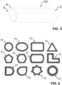
- An example of such a tube is illustrated in Figure 3 , wherein the tube 101 has a first end 2 and an opposite second end 3.
- the tube is then provided with the cut 4 to produce an electromagnetic coil, such that the cut 4 penetrates the tube wall 6 and extends from the first end 2 to the second end 3 such that the helical portion 5 is formed to the cut.
- the cut may be provided by, for example, laser cutting such that the tube 101 is fed to a mobile laser cutting head carrying out the cutting based on a predefined cutting path.
- the tube 101 may be moved relative to the cutting head by, for example, rotation.
- the tube 101 may be formed by extrusion, such that any of the cross-section variations of the coil 1 described above may be produced directly to the tube 101.
- An advantage of the manufacturing methods as described is that said shape variations may be produced inexpensively using largely automatized processes, such that no additional manufacturing steps are required for providing the shapes of the wall 6 as described above, such as the ribs 12, grooves 13 or connector members 15, for example.
- Another advantage of the manufacturing methods as described is the high degree of dimensional accuracy achievable for the coil 1.
- the dimensional deviation of said diameter from the target value may be in the range of, for example, 0.01 to 0.1 mm.
- the dimensional accuracy achievable by conventional manufacturing methods, involving bending of a blank material to form the coil is typically multiple times lower.
- the high dimensional accuracy provided by the disclosed method enables a higher degree of optimization of the electromagnetic properties of the coil 1, as well as higher efficiency of cooling achievable by utilizing additional cooling structures forming a contact with the coil.
- the tube 101 may be further cut at the first end 2 or the second end 3, or both, to define a connection terminal 10.
- the connection terminal may be provided by removing material at the first 2 and the second end 3 such that the outlines of the connection terminals 10 are defined by the cut provided to the tube 101 at this manufacturing step.
- Said cut may be provided to the tube 101 as a continuation to the cut 4 comprising the helical portion 5, or it may be provided as a separate cut during a following manufacturing step.
- connection terminals 10 may be provided to the connection terminals 10 by cutting.
- connection terminals 10 By providing the connection terminals 10 through a manufacturing step as described, the manufacture of the coil is further simplified as compared to the conventional methods in which the connection terminals are provided as separate parts.
- a path for the cut 4 may be set to define at least one of the helix angle 7, cut width 8 and cut extent 9 at the helical portion 5.
- the dimensions of the conduction path 17 forming in the coil 1 between the turns of the helix in the helical portion 5 may be determined, thereby influencing the electromagnetic properties of the coil 1.
- the cut extent 9 at the helical portion means the extent of the helical portion 5 as measured in the longitudinal direction of the coil 1.
- Said electromagnetic properties, including for example the inductance of the coil 1 are influenced largely by the length and the cross-section area 18 of the conduction path 17.
- the cross-section area 18 also influences the build-up of heat at the conduction path 17, such that reduction of the cross-section area 18 results in a higher degree of heating-up of the conduction path 17 when other factors are kept constant.
- the number of turns included in the conduction path 17 at the helical section is in praxis also determined by said helix angle 7, cut width 8 and cut extent 9, setting of these parameters greatly influences the length of the conduction path 17.
- the cut width 8 meaning the width of the cut 4 in the longitudinal direction of the coil 1, determines the distance between two adjacent turns of the conduction path 17 at the helical section 5, simultaneously influencing the cross-section area 18 of the conduction path.
- the desired cut width 8 may be achieved by, for example, adjusting the width of the cutting medium, such as the laser cutting head, or by forming the cut 4 between two adjacent cut lines, the distance between said cut lines matching the cut width 8.
- the setting of the path for the cut 4 may be based on at least one of inductance optimization, thermal optimization and dimensional optimization of the coil 1.
- the thermal optimization refers to optimization of heating-up behaviour of the coil 1 as a result of an electric current being conveyed or induced to it.
- the path for the cut 4 may be set so as to maximize the inductance of the coil 1 in an application wherein the properties of the electric current, such as voltage and frequency, as well as the outer dimensions of the coil 1 are predetermined, while enabling the temperature of the coil 1 to remain below a set maximum value.
- the path for the cut 4 may be set so as to minimize the outer dimensions of the coil 1, while maintaining the required electromagnetic properties of the coil 1, such as inductance.
- the cross-section area 18 of the conduction path may be kept smaller in the less critical parts of the conduction path, 17, enabling a higher inductance to be obtained for the coil without a substantial increase of its dimensions.
- the path for the cut 4 may be set by, for example, setting coordinate parameters to an actuating device responsible for moving the cutting medium, such as the laser cutting head, or the tube 101 to be cut.
- Said inductance optimization, thermal optimization and dimensional optimization of the coil 1 may be done by, for example, utilizing computer-based calculation- or modelling tools.
- Figures 8 and 9 illustrate schematically a part of a third variation of the coil 1, wherein Figure 9 illustrates roughly one half of the cross-section of the coil of Figure 8 so as to better illustrate the structure of the cut 4 and the conduction path 17 at the helical portion 5.
- the helical portion 5 of the cut 4 has a non-constant helix angle 7 and a non-constant cut width 8. More specifically, the helix angle 7 has been set to continuously fluctuate across the length of the cut 4, such that a wave-like pattern is formed to the helical portion 5.
- the helix angle 7 may also be set to have, for example, a constant value at a certain part of the cut at the helical portion 5 and another constant value at another part of the cut at the helical portion 5.
- the helix angle 7 may be set to alternate sharply along the cut 4 such that sharp angles are formed to the conduction path 17, or it may be set to alternate with smooth transitions as illustrated in the example of Figures 8 and 9 .
- the fluctuation of the helix angle 7 as described may be done to, for example, increase the length of the conduction path 17 at the helical portion 5, thereby influencing the electromagnetic properties of the coil 1.
- the cut 4 has a non-constant cut width 8 such that the distance between adjacent turns of the conduction path 17 at the helical section 5 is set to alternate. This may be done to, for example, increase the breakdown voltage of the coil 1 at a given area of the helical portion 5 by allowing for more separation between the turns, or to decrease or increase the cross-section area 18 of the conduction path 17 at a given portion.
- the conduction path 17 has a non-constant cross-section area 18 across the length of the conduction path 17, which in relation to the manufacturing method disclosed above may be achieved with the non-constant helix angle 7 and cut width 8.
- the cross-section area 18 may be determined by the setting of the helix angle 7 and the cut width 8. This may be done, for example, as a part of the inductance optimization, thermal optimization or dimensional optimization of the coil 1 as described above. In other variations of the coil 1, also just one of the helix angle 7 and the cut width 8 may be set to be non-constant, while maintaining a constant value for the other.
- the coil 1 as disclosed may be manufactured of several materials, preferably of electrically conductive materials such as metals.
- the coil may also be coated with an electrically insulating material after the disclosed manufacturing steps.
Landscapes
- Engineering & Computer Science (AREA)
- Power Engineering (AREA)
- Manufacturing & Machinery (AREA)
- Coils Or Transformers For Communication (AREA)
Abstract
The invention relates to a coil (1) enabling more efficient thermal management and a method for manufacturing the coil (1). The coil (1), which is an electromagnetic coil, has a first end (2) and an opposite second end (3) and is provided as a tube with a cut (4). The cut (4) penetrates a wall (6) of the tube, has a helical portion (5) and extends from the first end (2) to the second end (3).
Description
- This invention relates to a coil and a method of manufacturing a coil.
- In relation to coil manufacturing, especially manufacturing of electromagnetic coils, the methods typically used involve bending of continuous blank materials, such as rods or bars, into helical shapes. Typically, such electromagnetic coils are manufactured of metal, such as aluminum or copper, the blanks having a rectangular or spherical cross-section and forming a path of conduction for electric current. The helical shapes so produced typically have a linear or curved middle axis and a circular or oval cross-section.
- A problem typically associated with electromagnetic coils is their significant heating in certain applications where high electric currents are conveyed or induced to the coil. Said heating has therefore to be taken into account in the coil design, for example by increasing the conductive cross-section area or by providing the coil with sufficient means for cooling. Due to said limitations, the coils often need to be dimensioned larger than would be otherwise required, or their outer shape may not accommodate optimally the available space.
- An object of the present invention is to solve the above-mentioned drawbacks and to provide a solution facilitating a more efficient thermal management. These objects are achieved with a method according to
independent claim 1 and a coil according toindependent claim 6. - By providing a cut on a tube of an electrically conductive material, the cut extending from the first end to the second end of the tube and having a helical portion, coils with various shapes fulfilling different design criteria may be provided.
- Preferred embodiments of the invention are disclosed in the dependent claims.
- In the following the present invention will be described in closer detail by way of example and with reference to the attached drawings, in which
-
Figure 1 illustrates one embodiment of a coil, -
Figure 2 illustrates a variation of the coil ofFigure 1 , -
Figure 3 illustrates a tube for manufacturing the coil ofFigure 1 or 2 , -
Figure 4 illustrates cross-sections of different variations of the coil, -
Figure 5 illustrates a cross-section of a variation of the coil with cooling rods, -
Figure 6 illustrates a second variation of the coil, -
Figure 7 illustrates a cross-section of the coil ofFigure 6 , -
Figure 8 illustrates a third variation of the coil, and -
Figure 9 illustrates a part of a cross-section of the coil ofFigure 8 along the line A-A. -
Figures 1 and 2 illustrate one embodiment of acoil 1, as seen in a diagonal angle. As seen in this example, thecoil 1 is provided as a tube with afirst end 2 and an oppositesecond end 3 and is provided with acut 4. Thecut 4, which may be provided by laser cutting, for example, penetrates thetubular wall 6 of the coil and extends from thefirst end 2 to thesecond end 3. Thecut 4 has ahelical portion 5, which in said example extends along thewall 6 with aconstant helix angle 7 and cut width 8. In other words, thecut 4 extends from the outer surface of the coil to acavity 19 delimited by thetubular wall 6, such that aconduction path 17 is formed to thecoil 1 between the turns of the helix. The dimensions of thehelical portion 5, as well as the dimensions of theconduction path 17 may deviate from the example ofFigures 1 and 2 in other variations of the coil, so as to accommodate the requirements set for each use case. - In the examples of
Figures 1 and 2 , thecoil 1 also comprises aconnection terminal 10 connecting seamlessly to thefirst end 2 and thesecond end 3 of thecoil 1. In other words, theconnection terminals 10 have been provided without discontinuities caused by, for example, seams or attachment parts between theconnection terminals 10 and the ends of thecoil 1. The benefit of said arrangement over conventional coil structures, wherein the connection terminals are typically attached to the coil by welding or soldering, is that no disturbances for the passing of electric current are introduced by said discontinuities. Such disturbances typically introduce additional heating and power losses to the coil, and theconnection terminals 10 may need to be oversized to accommodate for this heating. In thecoil 1 according to the examples ofFigures 1 and 2 , the width of theconnection terminal 10 may be set independently of the width of theconduction path 17 in other parts of thecoil 1, so as to accommodate the heat build-up during use. In other variations of thecoil 1, theconnection terminal 10 may be provided to only one of the first 2 and thesecond end 3, or they may be completely omitted. -
Figure 6 illustrates a second variation of the coil. In this example, thewall 6 of the coil is provided withribs 12 extending in a longitudinal direction of thecoil 1. These ribs are visible especially inFigure 7 , illustrating across-section 11 of the coil ofFigure 6 in a direction parallel to the longitudinal direction. In this specific example, theribs 12 are provided both to the outside and to the inside of thewall 6, such that the ribs on the inside extend to thecavity 19 delimited by thewall 6. Theribs 12 in said example form an integral part of thewall 6 and may be provided as a part of the wall structure directly during the manufacture. In the example ofFigures 6 and 7 , theribs 12 form a uniform pattern circulating thewall 6, but may also be provided to, for example, only a part of the wall in other variations of the coil. Their number and dimensioning may also be set freely to accommodate the requirements set by a specific use case, or they may also be completely omitted from either one of the inside and the outside of thewall 6. - The
wall 6 according to the example ofFigures 6 and 7 is also provided withgrooves 13, said grooves extending in a longitudinal direction of thecoil 1 similarly to theribs 12. Thegrooves 13 may also be provided as a part of the wall structure directly during the manufacture, or they may be provided by, for example, milling or cutting. As in the case of theribs 12, thegrooves 13 may be dimensioned and located freely on thewall 6 based on the requirements of the use case, and they may be provided together with or independently of theribs 12. - By providing the
wall 6 with at least one of theribs 12 and thegrooves 13, the area of either one of the inner and the outer surface of thewall 6, or both, may be increased. Thereby, a larger cooling surface may be provided on either side of thewall 6 in comparison to a conventional coil, enabling more efficient cooling of the coil by introducing a cooling medium to the surfaces. Said cooling medium may be, for example, a liquid or a gas, and a different medium may be provided to each of the inner and the outer surfaces. Thereby, the inner side of thecoil 1 may be provided with, for example, a liquid cooling system, while the outer side of the coil may be provided with, for example, a gaseous cooling fluid. - In some variations of the
coil 1, the coil may also be provided with at least oneconnector member 15 for connecting to acooling rod 16. Such variation is illustrated in the example ofFigure 5 , illustrating schematically thecross-section 11 of the coil with fourcooling rods 16 in a direction parallel to the longitudinal direction. Said connecting may be accomplished by, for example, providing theconnector member 15 as a snap-fit -type connector fitting around thecooling rod 16, as illustrated in the example ofFigure 5 . Theconnector member 15 may be provided as a part of the coil structure directly during the coil manufacture, such that it connects seamlessly to thetubular wall 6. The number of thecooling rods 16 may be adjusted based on the cooling requirements of a specific use case, and they may comprise, for example, an internal channel for a cooling fluid or they may be arranged as solid objects of a thermally conductive material. In the example ofFigure 5 , theconnector members 15 and thecooling rods 16 are provided to the inside of thetubular wall 6, but may also be provided to its outer surface in other variations of the coil. - As illustrated in the example of
Figures 1 and 2 , thetubular wall 6 may also comprise a planar section 14 extending between thefirst end 2 and thesecond end 3. In other words, the planar section 14 may be provided as a section of thewall 6 defined by the cross-sectional shape of thecoil 1 in a direction parallel to the longitudinal direction. Said planar section may be provided to either one or both of the inner and the outer surface of thewall 6 in order to, for example, create a contact surface for a cooling structure provided to thecoil 1. Such a cooling structure may comprise, for example, a heat sink having a flat cooling surface to be brought into contact with the planar section 14. -
Figure 4 illustrates some possible variations of thecross-section 11 of thecoil 1 in a direction parallel to the longitudinal direction. As illustrated in the example, thetubular wall 6 of the coil may have a rectangular, angular orasymmetric cross-section 11 in addition to the spherical and oval variations illustrated in the previous examples. In this context, the term angular means any shape of thewall cross-section 11 provided with one or more angles, such as triangular, pentagonal, hexagonal or star-like shapes, for example. This type ofcoil cross-section 11 may be used to increase the surface area of thewall 6 in comparison to a spherical or oval cross-section, for example, so as to increase the efficiency of cooling of thecoil 1 by providing a larger cooling surface. The asymmetric cross-section variations may include, for example, D-shapes or L-shapes, wherein thecoil wall 6 is arranged asymmetrically relative to the longitudinal middle axis of the coil. The shape and dimensions of the wall cross-section may be chosen based on, for example, the shape and the volume of the space available for thecoil 1 in a given application or the surface area required for enabling sufficient cooling of the coil. - The coil according to the examples of
Figures 1, 2 and4 to 9 may be manufactured by first taking into use atube 101 with a wall of an electrically conductive material. An example of such a tube is illustrated inFigure 3 , wherein thetube 101 has afirst end 2 and an oppositesecond end 3. The tube is then provided with thecut 4 to produce an electromagnetic coil, such that thecut 4 penetrates thetube wall 6 and extends from thefirst end 2 to thesecond end 3 such that thehelical portion 5 is formed to the cut. The cut may be provided by, for example, laser cutting such that thetube 101 is fed to a mobile laser cutting head carrying out the cutting based on a predefined cutting path. Alternatively, or in addition to the movement of the laser cutting head, thetube 101 may be moved relative to the cutting head by, for example, rotation. Thetube 101 may be formed by extrusion, such that any of the cross-section variations of thecoil 1 described above may be produced directly to thetube 101. An advantage of the manufacturing methods as described is that said shape variations may be produced inexpensively using largely automatized processes, such that no additional manufacturing steps are required for providing the shapes of thewall 6 as described above, such as theribs 12,grooves 13 orconnector members 15, for example. - Another advantage of the manufacturing methods as described is the high degree of dimensional accuracy achievable for the
coil 1. For a coil having a diameter in the range of, for example, 100 mm, the dimensional deviation of said diameter from the target value may be in the range of, for example, 0.01 to 0.1 mm. By contrast, the dimensional accuracy achievable by conventional manufacturing methods, involving bending of a blank material to form the coil, is typically multiple times lower. The high dimensional accuracy provided by the disclosed method enables a higher degree of optimization of the electromagnetic properties of thecoil 1, as well as higher efficiency of cooling achievable by utilizing additional cooling structures forming a contact with the coil. That is, in order to provide efficient heat transfer between thecoil 1 and the cooling structure, such as a coolingrod 16, a tight interface between the coil and the surface of the cooling structure is required. This may limit the use of such cooling structures in relation to coils manufactured by said conventional methods, wherein the low degree of dimensional accuracy may impair the integrity of the interface between the coil and the cooling structure. - In the manufacturing method of the
coil 1 according to the examples ofFigures 1 and 2 , thetube 101 may be further cut at thefirst end 2 or thesecond end 3, or both, to define aconnection terminal 10. In other words, the connection terminal may be provided by removing material at the first 2 and thesecond end 3 such that the outlines of theconnection terminals 10 are defined by the cut provided to thetube 101 at this manufacturing step. This way, theconnection terminals 10 are provided so as to form a unibody structure with the other parts of thecoil 1, and no discontinuities are formed to the structure between theconnection terminals 10 and said other parts. Said cut may be provided to thetube 101 as a continuation to thecut 4 comprising thehelical portion 5, or it may be provided as a separate cut during a following manufacturing step. At this manufacturing step, also additional shapes, such as connection holes, may be provided to theconnection terminals 10 by cutting. By providing theconnection terminals 10 through a manufacturing step as described, the manufacture of the coil is further simplified as compared to the conventional methods in which the connection terminals are provided as separate parts. - Before carrying out the cutting, a path for the
cut 4 may be set to define at least one of thehelix angle 7, cut width 8 and cutextent 9 at thehelical portion 5. By defining at least one of said parameters, also the dimensions of theconduction path 17 forming in thecoil 1 between the turns of the helix in thehelical portion 5 may be determined, thereby influencing the electromagnetic properties of thecoil 1. In this context, thecut extent 9 at the helical portion means the extent of thehelical portion 5 as measured in the longitudinal direction of thecoil 1. Said electromagnetic properties, including for example the inductance of thecoil 1, are influenced largely by the length and thecross-section area 18 of theconduction path 17. On the other hand, thecross-section area 18 also influences the build-up of heat at theconduction path 17, such that reduction of thecross-section area 18 results in a higher degree of heating-up of theconduction path 17 when other factors are kept constant. - As in the context of the examples of
Figures 1, 2 and4 to 9 , the number of turns included in theconduction path 17 at the helical section is in praxis also determined by saidhelix angle 7, cut width 8 and cutextent 9, setting of these parameters greatly influences the length of theconduction path 17. The cut width 8, meaning the width of thecut 4 in the longitudinal direction of thecoil 1, determines the distance between two adjacent turns of theconduction path 17 at thehelical section 5, simultaneously influencing thecross-section area 18 of the conduction path. The desired cut width 8 may be achieved by, for example, adjusting the width of the cutting medium, such as the laser cutting head, or by forming thecut 4 between two adjacent cut lines, the distance between said cut lines matching the cut width 8. - The setting of the path for the
cut 4 may be based on at least one of inductance optimization, thermal optimization and dimensional optimization of thecoil 1. In this context, the thermal optimization refers to optimization of heating-up behaviour of thecoil 1 as a result of an electric current being conveyed or induced to it. For example, the path for thecut 4 may be set so as to maximize the inductance of thecoil 1 in an application wherein the properties of the electric current, such as voltage and frequency, as well as the outer dimensions of thecoil 1 are predetermined, while enabling the temperature of thecoil 1 to remain below a set maximum value. In another example, the path for thecut 4 may be set so as to minimize the outer dimensions of thecoil 1, while maintaining the required electromagnetic properties of thecoil 1, such as inductance. In praxis, it is often desirable to maximize the inductance of thecoil 1, for example by increasing the length of theconduction path 17, while in order to simultaneously avoid overheating of the coil, it is necessary to keep thecross-section area 18 of the conduction path sufficiently large. In such case, for example by setting at least one of thehelix angle 7 and cut width 8 so as to increase thecross-section area 18 at a certain section of theconduction path 17, the resulting reduction of heat build-up may be targeted to pre-identified hotspot areas of thecoil 1. Thereby, thecross-section area 18 may be kept smaller in the less critical parts of the conduction path, 17, enabling a higher inductance to be obtained for the coil without a substantial increase of its dimensions. - The path for the
cut 4 may be set by, for example, setting coordinate parameters to an actuating device responsible for moving the cutting medium, such as the laser cutting head, or thetube 101 to be cut. Said inductance optimization, thermal optimization and dimensional optimization of thecoil 1 may be done by, for example, utilizing computer-based calculation- or modelling tools. -
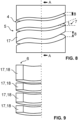
Figures 8 and 9 illustrate schematically a part of a third variation of thecoil 1, whereinFigure 9 illustrates roughly one half of the cross-section of the coil ofFigure 8 so as to better illustrate the structure of thecut 4 and theconduction path 17 at thehelical portion 5. In this example, thehelical portion 5 of thecut 4 has anon-constant helix angle 7 and a non-constant cut width 8. More specifically, thehelix angle 7 has been set to continuously fluctuate across the length of thecut 4, such that a wave-like pattern is formed to thehelical portion 5. In other variations of thecoil 1, thehelix angle 7 may also be set to have, for example, a constant value at a certain part of the cut at thehelical portion 5 and another constant value at another part of the cut at thehelical portion 5. Thehelix angle 7 may be set to alternate sharply along thecut 4 such that sharp angles are formed to theconduction path 17, or it may be set to alternate with smooth transitions as illustrated in the example ofFigures 8 and 9 . The fluctuation of thehelix angle 7 as described may be done to, for example, increase the length of theconduction path 17 at thehelical portion 5, thereby influencing the electromagnetic properties of thecoil 1. - In the example of
Figures 8 and 9 , thecut 4 has a non-constant cut width 8 such that the distance between adjacent turns of theconduction path 17 at thehelical section 5 is set to alternate. This may be done to, for example, increase the breakdown voltage of thecoil 1 at a given area of thehelical portion 5 by allowing for more separation between the turns, or to decrease or increase thecross-section area 18 of theconduction path 17 at a given portion. In said example, theconduction path 17 has anon-constant cross-section area 18 across the length of theconduction path 17, which in relation to the manufacturing method disclosed above may be achieved with thenon-constant helix angle 7 and cut width 8. In other words, when the shape of thetubular wall 6 is kept constant across the longitudinal direction of thecoil 1, thetubular wall 6 together with thehelical portion 5 delimiting theconduction path 17, thecross-section area 18 may be determined by the setting of thehelix angle 7 and the cut width 8. This may be done, for example, as a part of the inductance optimization, thermal optimization or dimensional optimization of thecoil 1 as described above. In other variations of thecoil 1, also just one of thehelix angle 7 and the cut width 8 may be set to be non-constant, while maintaining a constant value for the other. - The
coil 1 as disclosed may be manufactured of several materials, preferably of electrically conductive materials such as metals. The coil may also be coated with an electrically insulating material after the disclosed manufacturing steps. - It is to be understood that the above description and the accompanying figures are only intended to illustrate the present invention. It will be obvious to a person skilled in the art that the invention can be varied and modified without departing from the scope of the invention.
Claims (15)
- A method for manufacturing a coil (1), characterized in that the method comprises:taking into use a tube (101) with a wall of an electrically conductive material, the tube (101) having a first end (2) and an opposite second end (3), andproviding a cut (4) in the wall (6) of the tube (101), which cut extends from the first end (2) to the second end (3), and which cut has a helical portion (5), wherein the cut (4) penetrates the tube wall (6) to produce an electromagnetic coil.
- The method for manufacturing a coil (1) according to claim 1, characterized in that the cut (4) is provided by laser cutting.
- The method for manufacturing a coil (1) according to claim 1 or 2, characterized in that said taking into use comprises extrusion of the tube (101).
- The method for manufacturing a coil (1) according to any one of the claims 1 to 3, characterized in that the method further comprises:
setting a path for the cut (4) to define at least one of a helix angle (7), cut width (8) and cut extent (9) at the helical portion (5) based on at least one of inductance optimization, thermal optimization and dimensional optimization of the coil (1). - The method for manufacturing a coil (1) according to any one of the claims 1 to 4, characterized in that the method further comprises:
cutting the tube (101) at at least one of the first end (2) and the second end (3) to define a connection terminal (10). - Acoil(1),characterized in thatthe coil (1) has a first end (2) and an opposite second end (3), andthe coil (1) is an electromagnetic coil provided as a tube with a cut (4), which cut (4) penetrates a wall (6) of the tube, has a helical portion, and extends from the first end (2) to the second end (3) .
- The coil (1) according to claim 6, characterized in that the coil has a rectangular, angular or asymmetric cross-section (11).
- The coil (1) according to claim 6 or 7, characterized in that the wall (6) is provided with at least one of a rib (12) and a groove (13) extending in a longitudinal direction of the coil (1).
- The coil (1) according to claim 8, characterized in that the at least one of a rib (12) and a groove (13) is provided to an inside of the wall (6).
- The coil (1) according to any one of the claims 6 to 9, characterized in that the wall (6) comprises a planar section (14) extending between the first end (2) and the second end (3).
- The coil (1) according to any one of the claims 6 to 10, characterized in that the coil (1) further comprises at least one connection terminal (10), wherein the at least one connection terminal (10) connects seamlessly to the first end (2) or the second end (3) of the coil (1).
- The coil (1) according to any one of the claims 6 to 11, characterized in that the coil (1) is provided with at least one connector member (15) for connecting to a cooling rod (16), wherein the at least one connector member (15) connects seamlessly to the wall (6).
- The coil (1) according to claim 12, characterized in that the at least one connector member (15) is provided to the inside of the wall (6).
- The coil (1) according to any one of the claims 6 to 13, characterized in that the helical portion (5) of the cut (4) has at least one of a non-constant helix angle (7) and a non-constant cut width (8).
- The coil (1) according to claim 14, characterized in that the coil (1) has a conduction path (17) delimited by at least the helical portion (5), wherein the conduction path (17) has a non-constant cross-section area (18) across the length of the conduction path (17).
Priority Applications (1)
| Application Number | Priority Date | Filing Date | Title |
|---|---|---|---|
| EP22207740.6A EP4372770A1 (en) | 2022-11-16 | 2022-11-16 | Coil and method of manufacturing a coil |
Applications Claiming Priority (1)
| Application Number | Priority Date | Filing Date | Title |
|---|---|---|---|
| EP22207740.6A EP4372770A1 (en) | 2022-11-16 | 2022-11-16 | Coil and method of manufacturing a coil |
Publications (1)
| Publication Number | Publication Date |
|---|---|
| EP4372770A1 true EP4372770A1 (en) | 2024-05-22 |
Family
ID=84359308
Family Applications (1)
| Application Number | Title | Priority Date | Filing Date |
|---|---|---|---|
| EP22207740.6A Withdrawn EP4372770A1 (en) | 2022-11-16 | 2022-11-16 | Coil and method of manufacturing a coil |
Country Status (1)
| Country | Link |
|---|---|
| EP (1) | EP4372770A1 (en) |
Citations (12)
| Publication number | Priority date | Publication date | Assignee | Title |
|---|---|---|---|---|
| US3466743A (en) * | 1965-07-02 | 1969-09-16 | Gen Electric | Spiral coil comprising a tubular blank with parallel,rectilinear cuts therein |
| US3731243A (en) * | 1971-12-08 | 1973-05-01 | A Davis | Inductive winding |
| JPH07163100A (en) * | 1993-12-07 | 1995-06-23 | Seiko Epson Corp | Coil and coil manufacturing method |
| US5428337A (en) * | 1992-02-21 | 1995-06-27 | Vlt Corporation | Conductive winding |
| JPH1197270A (en) * | 1997-09-18 | 1999-04-09 | Tdk Corp | Flat-type coil and its manufacture |
| DE202009003845U1 (en) * | 2008-03-20 | 2009-06-10 | Abb Oy | Inductive electronic component |
| US20090206974A1 (en) * | 2008-02-18 | 2009-08-20 | Rainer Meinke | Helical Coil Design and Process For Direct Fabrication From A Conductive Layer |
| DE102012011554A1 (en) * | 2012-06-11 | 2013-12-12 | Fraunhofer-Gesellschaft zur Förderung der angewandten Forschung e.V. | Method for manufacturing electrical coil for e.g. electric motor, involves forming coil head of loop from tubular metal semi-finished product, and removing regions of tubular metal semi-finished product, for forming conductor loop |
| WO2019066568A1 (en) * | 2017-09-29 | 2019-04-04 | 한국생산기술연구원 | Method for manufacturing coil unit |
| US20200234860A1 (en) * | 2017-02-28 | 2020-07-23 | Nidec-Read Corporation | Coiled electronic component, coil component, manufacturing method of coil component, inductance element, t-type filter, oscillation circuit, and manufacturing method of inductance element |
| US20220093324A1 (en) * | 2019-02-15 | 2022-03-24 | Tdk Electronics Ag | Coil and Method for Producing A Coil |
| US20220277887A1 (en) * | 2020-04-21 | 2022-09-01 | Tdk Electronics Ag | Coil and Method of Manufacturing the Coil |
-
2022
- 2022-11-16 EP EP22207740.6A patent/EP4372770A1/en not_active Withdrawn
Patent Citations (12)
| Publication number | Priority date | Publication date | Assignee | Title |
|---|---|---|---|---|
| US3466743A (en) * | 1965-07-02 | 1969-09-16 | Gen Electric | Spiral coil comprising a tubular blank with parallel,rectilinear cuts therein |
| US3731243A (en) * | 1971-12-08 | 1973-05-01 | A Davis | Inductive winding |
| US5428337A (en) * | 1992-02-21 | 1995-06-27 | Vlt Corporation | Conductive winding |
| JPH07163100A (en) * | 1993-12-07 | 1995-06-23 | Seiko Epson Corp | Coil and coil manufacturing method |
| JPH1197270A (en) * | 1997-09-18 | 1999-04-09 | Tdk Corp | Flat-type coil and its manufacture |
| US20090206974A1 (en) * | 2008-02-18 | 2009-08-20 | Rainer Meinke | Helical Coil Design and Process For Direct Fabrication From A Conductive Layer |
| DE202009003845U1 (en) * | 2008-03-20 | 2009-06-10 | Abb Oy | Inductive electronic component |
| DE102012011554A1 (en) * | 2012-06-11 | 2013-12-12 | Fraunhofer-Gesellschaft zur Förderung der angewandten Forschung e.V. | Method for manufacturing electrical coil for e.g. electric motor, involves forming coil head of loop from tubular metal semi-finished product, and removing regions of tubular metal semi-finished product, for forming conductor loop |
| US20200234860A1 (en) * | 2017-02-28 | 2020-07-23 | Nidec-Read Corporation | Coiled electronic component, coil component, manufacturing method of coil component, inductance element, t-type filter, oscillation circuit, and manufacturing method of inductance element |
| WO2019066568A1 (en) * | 2017-09-29 | 2019-04-04 | 한국생산기술연구원 | Method for manufacturing coil unit |
| US20220093324A1 (en) * | 2019-02-15 | 2022-03-24 | Tdk Electronics Ag | Coil and Method for Producing A Coil |
| US20220277887A1 (en) * | 2020-04-21 | 2022-09-01 | Tdk Electronics Ag | Coil and Method of Manufacturing the Coil |
Similar Documents
| Publication | Publication Date | Title |
|---|---|---|
| CA2015533C (en) | Semi-flexible double-ridge waveguide | |
| CN105229757B (en) | The induction coil of coil shape with dynamically changeable | |
| CA2474558C (en) | Slotted tube with reversible usage for heat exchangers | |
| EP1540260B1 (en) | Method of manufacturing a heat exchanger | |
| US20100109831A1 (en) | Induction coil without a weld | |
| KR20210137150A (en) | Electric Fluid Flow Heater With Heating Element Stabilization Fins | |
| EP1271574B1 (en) | Circular-development planar windings and inductive component made with one or more of said windings | |
| EP4372770A1 (en) | Coil and method of manufacturing a coil | |
| US20240255234A1 (en) | Heat exchanger with heat transfer augmentation features | |
| US10471535B2 (en) | Welding electrode cap | |
| EP4317892A1 (en) | Heat exchanger with heat transfer augmentation features | |
| JP7711216B2 (en) | high current ribbon inductor | |
| US5052479A (en) | Tube for coolant condenser | |
| US11895744B2 (en) | Electric tubular heating element and related method | |
| US20180123419A1 (en) | Heat sink for an electric machine and method for producing said heat sink | |
| EP0626797B1 (en) | Tubing shape, particularly for fabricating an induction coil | |
| EP4097746B1 (en) | Electro-magnetic coil with coolant permeability | |
| US20220347737A1 (en) | Method for manufacturing double-pipe heat exchanger | |
| JP3875359B2 (en) | Manufacturing method of high frequency induction heating coil | |
| US12396072B2 (en) | Multi-layer parallel plane inductor with field control pockets | |
| JPH02301938A (en) | Traveling wave tube | |
| JP2024087621A (en) | Heat transfer tube with internal spiral grooves, design method thereof, and heat exchanger | |
| MXPA01005372A (en) | High frequency contact welding apparatus with skewed contacts. | |
| JPH06246343A (en) | Heat transfer tube and manufacture thereof |
Legal Events
| Date | Code | Title | Description |
|---|---|---|---|
| PUAI | Public reference made under article 153(3) epc to a published international application that has entered the european phase |
Free format text: ORIGINAL CODE: 0009012 |
|
| STAA | Information on the status of an ep patent application or granted ep patent |
Free format text: STATUS: THE APPLICATION HAS BEEN PUBLISHED |
|
| AK | Designated contracting states |
Kind code of ref document: A1 Designated state(s): AL AT BE BG CH CY CZ DE DK EE ES FI FR GB GR HR HU IE IS IT LI LT LU LV MC ME MK MT NL NO PL PT RO RS SE SI SK SM TR |
|
| STAA | Information on the status of an ep patent application or granted ep patent |
Free format text: STATUS: THE APPLICATION IS DEEMED TO BE WITHDRAWN |
|
| 18D | Application deemed to be withdrawn |
Effective date: 20241123 |