EP4372529A1 - Touch panel and control device - Google Patents
Touch panel and control device Download PDFInfo
- Publication number
- EP4372529A1 EP4372529A1 EP23209816.0A EP23209816A EP4372529A1 EP 4372529 A1 EP4372529 A1 EP 4372529A1 EP 23209816 A EP23209816 A EP 23209816A EP 4372529 A1 EP4372529 A1 EP 4372529A1
- Authority
- EP
- European Patent Office
- Prior art keywords
- component
- vibration generating
- suspended
- touch panel
- touch screen
- Prior art date
- Legal status (The legal status is an assumption and is not a legal conclusion. Google has not performed a legal analysis and makes no representation as to the accuracy of the status listed.)
- Pending
Links
Images
Classifications
-
- G—PHYSICS
- G06—COMPUTING OR CALCULATING; COUNTING
- G06F—ELECTRIC DIGITAL DATA PROCESSING
- G06F3/00—Input arrangements for transferring data to be processed into a form capable of being handled by the computer; Output arrangements for transferring data from processing unit to output unit, e.g. interface arrangements
- G06F3/01—Input arrangements or combined input and output arrangements for interaction between user and computer
- G06F3/016—Input arrangements with force or tactile feedback as computer generated output to the user
-
- G—PHYSICS
- G06—COMPUTING OR CALCULATING; COUNTING
- G06F—ELECTRIC DIGITAL DATA PROCESSING
- G06F3/00—Input arrangements for transferring data to be processed into a form capable of being handled by the computer; Output arrangements for transferring data from processing unit to output unit, e.g. interface arrangements
- G06F3/01—Input arrangements or combined input and output arrangements for interaction between user and computer
- G06F3/03—Arrangements for converting the position or the displacement of a member into a coded form
- G06F3/033—Pointing devices displaced or positioned by the user, e.g. mice, trackballs, pens or joysticks; Accessories therefor
- G06F3/0354—Pointing devices displaced or positioned by the user, e.g. mice, trackballs, pens or joysticks; Accessories therefor with detection of two-dimensional [2D] relative movements between the device, or an operating part thereof, and a plane or surface, e.g. 2D mice, trackballs, pens or pucks
- G06F3/03547—Touch pads, in which fingers can move on a surface
-
- G—PHYSICS
- G06—COMPUTING OR CALCULATING; COUNTING
- G06F—ELECTRIC DIGITAL DATA PROCESSING
- G06F3/00—Input arrangements for transferring data to be processed into a form capable of being handled by the computer; Output arrangements for transferring data from processing unit to output unit, e.g. interface arrangements
- G06F3/01—Input arrangements or combined input and output arrangements for interaction between user and computer
- G06F3/03—Arrangements for converting the position or the displacement of a member into a coded form
- G06F3/041—Digitisers, e.g. for touch screens or touch pads, characterised by the transducing means
-
- G—PHYSICS
- G06—COMPUTING OR CALCULATING; COUNTING
- G06F—ELECTRIC DIGITAL DATA PROCESSING
- G06F2203/00—Indexing scheme relating to G06F3/00 - G06F3/048
- G06F2203/041—Indexing scheme relating to G06F3/041 - G06F3/045
- G06F2203/04103—Manufacturing, i.e. details related to manufacturing processes specially suited for touch sensitive devices
Definitions
- the present invention relates to the field of touch control, in particular a touch panel and a control device.
- a protective bag will be used to protect the touch panel when a doctor is performing surgery, to prevent blood or sweat stains or other liquids from contaminating the touch panel during surgery and thus affecting the functioning of the touch panel.
- the doctor will be wearing gloves, and such double isolation might result in erroneous operations or failed operations when the doctor is operating the touch panel.
- the doctor can only confirm whether a finger has touched the screen by subjective vision or touch screen audio reminder, in order to judge whether an operation has been performed correctly.
- embodiments of the present invention propose a touch panel in one aspect, and a control device in another aspect, to achieve feedback confirmation of a touch operation.
- a touch panel proposed in embodiments of the present invention comprises: a suspended component, comprising a touch screen; a fixed component, for supporting the suspended component; an elastic element, configured to be connected between the suspended component and the fixed component, the elastic element generating a force causing the suspended component to return to a specific position relative to the fixed component, in response to deviation of the suspended component from the specific position; and a vibration generating component, at least one part of which is disposed on the suspended component, the vibration generating component being able to drive the suspended component to deviate from the specific position, and the vibration generating component cooperating with the elastic element to make the suspended component vibrate.
- the direction of the vibration is parallel to a plane in which the touch screen lies.
- the vibration generating component comprises a first vibration generating member disposed on the suspended component and a second vibration generating member disposed on the fixed component, the first vibration generating member and the second vibration generating member being arranged opposite each other in a direction parallel to the plane in which the touch screen lies; the vibration generating component drives the suspended component to deviate from the specific position, by means of an electromagnetic force generated between the first vibration generating member and the second vibration generating member in a direction parallel to the plane in which the touch screen lies.
- the electromagnetic force generated between the first vibration generating member and the second vibration generating member is an attractive force; or the electromagnetic force generated between the first vibration generating member and the second vibration generating member is a repulsive force.
- the fixed component further comprises a PCB, the PCB being separately electrically connected to the touch screen and the vibration generating component.
- the vibration generating component comprises a push-rod disposed on the suspended component and a cam member disposed on the fixed component; the vibration generating component drives the suspended component to deviate from the specific position, by means of a pushing force applied to the push-rod by the cam member in a direction parallel to the plane in which the touch screen lies.
- the touch panel further comprises: a sliding mounting member, which connects the fixed component to the suspended component in a direction parallel to the plane in which the touch screen lies, enabling the suspended component to deviate from the specific position relative to the fixed component in a direction parallel to the plane in which the touch screen lies; the elastic element being disposed on the sliding mounting member, and guided by the sliding mounting member.
- the sliding mounting member is a partially threaded screw member.
- a region of contact between the suspended component and the fixed component in a direction perpendicular to the plane in which the touch screen lies is further provided with a point-contact silicone rubber pad.
- the suspended component further comprises: a front housing, the touch screen being disposed at an outer side of the front housing, and said at least one part of the vibration generating component being disposed at an inner side of the front housing;
- the fixed component further comprises: a mounting plate, a support and a rear housing; the sliding mounting member is connected between the front housing and the support; the mounting plate is fixed to the support, a part of the vibration generating component other than said at least one part is disposed at a side of the mounting plate that faces the front housing, and the rear housing is disposed at the periphery of the mounting plate and the support and connected to the front housing.
- the touch panel further comprises: sealing foam disposed between the front housing and the rear housing.
- the fixed component further comprises: a counterweight which, together with the rear housing, forms a fixed base.
- Embodiments of the present invention further provide a control device, comprising the touch panel described in any one of the embodiments above.
- control device is a medical device or a motor vehicle.
- touch feedback can be realized in a large, heavy touch panel due to the inclusion of the suspended component and the fixed component in the control panel in embodiments of the present invention, the suspended component being able to move relative to the fixed component when the touch screen on the suspended component receives a touch signal, and the elastic element being used to realize sustainable vibration feedback.
- touch panel in embodiments of the present invention is structurally simple, flexible and reliable.
- a touch panel may be configured to comprise a suspended component and a fixed component, wherein the fixed component is used to support the suspended component; a touch screen is disposed on the suspended component, can move relative to the fixed component when the touch screen receives a touch signal of a finger, etc., and can be helped to return by an elastic element.
- the touch panel may comprise a suspended component comprising a touch screen, a fixed component for supporting the suspended component, an elastic element configured to be connected between the suspended component and the fixed component, and a vibration generating component.
- the elastic element can generate a force causing the suspended component to return to a specific position relative to the fixed component, in response to deviation of the suspended component from the specific position.
- At least one part of the vibration generating component is disposed on the suspended component, the vibration generating component being able to drive the suspended component to deviate from the specific position, and the vibration generating component cooperating with the elastic element to make the suspended component vibrate.
- the direction of the vibration is parallel to a plane in which the touch screen lies, or perpendicular to the plane in which the touch screen lies.
- exemplary and “schematic” mean “serving as an instance, example or illustration”. No drawing or embodiment described herein as “exemplary” or “schematic” should be interpreted as a more preferred or more advantageous technical solution.
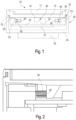
- Fig. 1 shows a schematic structural diagram of a touch panel in an embodiment.
- the touch panel in this embodiment comprises: a suspended component 10, a fixed component 20, a vibration generating component 30 and an elastic element 40.
- the suspended component 10 comprises a touch screen 11.
- the fixed component 20 is used to support the suspended component 10.
- the suspended component 10 can move relative to the fixed component 20 when the touch screen 11 receives a touch signal.
- At least one part of the vibration generating component 30 is disposed on the suspended component 10, and the vibration generating component 30 can drive the suspended component 10 to deviate from a specific position relative to the fixed component 20.
- the elastic element 40 is connected between the suspended component 10 and the fixed component 20, and used to generate a force causing the suspended component 10 to return to the specific position, in response to deviation of the suspended component 10 from the specific position.
- the vibration generating component 30 cooperates with the elastic element 40 to make the suspended component 10 vibrate.
- the vibration generating component 30 in this embodiment comprises a first vibration generating member 31 disposed on the suspended component 10 and a second vibration generating member 32 disposed on the fixed component 20, wherein the first vibration generating member 31 and second vibration generating member 32 are arranged opposite each other in a direction parallel to the plane in which the touch screen 11 lies.
- the vibration generating component 30 drives the suspended component 10 to deviate from a specific position relative to the fixed component 20, by means of an electromagnetic force generated between the first vibration generating member 31 and second vibration generating member 32 in a direction parallel to the plane in which the touch screen 11 lies.
- the direction of vibration may be perpendicular to the plane in which the touch screen 11 lies, in which case the first vibration generating member 31 and second vibration generating member 32 may be arranged opposite each other in a direction perpendicular to the plane in which the touch screen 11 lies, and the vibration generating component 30 drives the suspended component 10 to deviate from a specific position relative to the fixed component 20, by means of an electromagnetic force generated between the first vibration generating member 31 and second vibration generating member 32 in a direction perpendicular to the plane in which the touch screen 11 lies.
- the electromagnetic force generated between the first vibration generating member 31 and second vibration generating member 32 may be an attractive force.
- the first vibration generating member 31 or second vibration generating member 32 may be controlled to be energized and generate magnetism, thereby generating an attractive force between the first vibration generating member 31 and second vibration generating member 32, driving the suspended component 10 to move in a set direction under the action of the attractive force, and compressing or pulling the elastic element 40 to generate elastic potential energy; when the first vibration generating member 31 or second vibration generating member 32 is de-energized and the magnetism disappears, the elastic element 40 releases the elastic potential energy and drives the suspended component 10 to return.
- the specific position of the suspended component 10 relative to the fixed component 20 is a position to which the suspended component 10 is caused to return.
- the electromagnetic force generated between the first vibration generating member 31 and second vibration generating member 32 may be a repulsive force.
- the first vibration generating member 31 or second vibration generating member 32 may be kept energized to generate magnetism, thereby generating a repulsive force between the first vibration generating member 31 and second vibration generating member 32, and compressing or pulling the elastic element 40 to generate elastic potential energy, while causing the suspended component 10 to remain at a set position;
- the touch screen 11 receives a touch signal
- the first vibration generating member 31 or second vibration generating member 32 is controlled to be de-energized, the magnetism disappears, and the elastic element 40 releases the elastic potential energy and drives the suspended component 10 to move in a set direction;
- the first vibration generating member 31 or second vibration generating member 32 is energized again and generates magnetism, a repulsive force is generated between the first vibration generating member 31 and second vibration generating member 32, and the suspended component 10 is driven to return under the action of the repulsive force
- the suspended component 10 further comprises a front housing 12.
- the touch screen 11 is disposed at an outer side of the front housing 12, e.g. above the front housing as in Fig. 1
- the first vibration generating member 31 is disposed at an inner side of the front housing 13, e.g. below the front housing as in Fig. 1 .
- the fixed component 20 comprises a PCB 21, a mounting plate 22, a support 23 and a rear housing 24.
- the PCB 21 is separately electrically connected to the touch screen 11 and the vibration generating component 30, e.g. electrically connected to the first vibration generating member 31 or second vibration generating member 32.
- the mounting plate 22 is fixed to the support 23; the PCB 21 is disposed at one side of the mounting plate 22, e.g. below the mounting plate as in Fig. 1 ; and the second vibration generating member 32 is disposed at the side of the mounting plate 22 that faces the front housing 12, e.g. above the mounting plate as in Fig. 1 .
- the PCB 21 may be disposed at other positions, which are not defined here.
- the fixed component 20 may support the suspended component 10 in various ways.
- Fig. 2 shows a mounting method in the case where the direction of the vibration is parallel to the plane in which the touch screen 11 lies.
- the fixed component 20 is connected to the suspended component 10 in a direction parallel to the plane in which the touch screen lies by means of a sliding mounting member 50, such that the suspended component 10 can move relative to the fixed component 20 in a direction parallel to the plane in which the touch screen lies.
- the sliding mounting member 30 is connected between the front housing 12 and the support 23.
- the elastic element 40 is disposed on the sliding mounting member 50, and guided by the sliding mounting member 50.
- the sliding mounting member 50 may be a partially threaded screw member.
- the supporting of the suspended component 10 by the fixed component 20 may be accomplished by means of an elastic element of higher rigidity, i.e. the fixed component 20 and suspended component 10 are connected by an elastic element of higher rigidity directly.
- the rear housing 24 is disposed at the periphery of the PCB 21, the mounting plate 22 and the support 23, and connected to the front housing 12.
- a region of contact between the suspended component 10 and the fixed component 20 in a direction perpendicular to the plane in which the touch screen lies is further provided with a point-contact silicone rubber pad 60. That is, contact between the front housing 12 and the support 23 in the direction perpendicular to the touch screen is designed as point contact rather than surface contact, thereby reducing friction in the direction of movement when the suspended component 10 moves relative to the fixed component 20; and the provision of the silicone rubber pad adhered in the middle of the point contact can avoid a situation in which noise is generated by the suspended component 10 and the fixed component 20 rubbing against each other.
- the reason for choosing silicone rubber is that the properties of silicone rubber do not change much when it is compressed for a long period of time.
- a full ring of sealing foam 70 may be further provided between the front housing 12 and the rear housing 24 in this embodiment, to realize functions such as waterproofing, dustproofing, noise absorption (sealing the entire product), and cushioning (avoiding noise due to structural collisions).
- the fixed component 20 in this embodiment may further comprise: a counterweight 25, which may together with the rear housing 24 form a fixed base, to avoid a situation in which body vibration arises as the suspended structure 10 vibrates, causing resonance and thus affecting the vibration feedback result.
- a counterweight 25 may together with the rear housing 24 form a fixed base, to avoid a situation in which body vibration arises as the suspended structure 10 vibrates, causing resonance and thus affecting the vibration feedback result.
- the counterweight 25 need not be used.
- the vibration generating component may have other structural forms.
- the vibration generating component may employ a cam mechanism.
- the vibration generating component may comprise a push-rod (not shown in the figures) disposed on the suspended component and a cam member (not shown in the figures) disposed on the fixed component.
- the vibration generating component may drive the suspended component to deviate from the specific position by means of a pushing force applied to the push-rod by the cam member.
- the pushing force may be in a direction parallel to the plane in which the touch screen lies; in the case where the direction of the vibration is perpendicular to the plane in which the touch screen 11 lies, the pushing force may be in a direction perpendicular to the plane in which the touch screen lies.
- control device comprising the touch panel described in any one of the embodiments above.
- the control device may be a medical device or a motor vehicle, etc.
- touch feedback can be realized due to the inclusion of the suspended component and the fixed component, the suspended component being able to move relative to the fixed component when the touch screen on the suspended component receives a touch signal, and return when the touch signal disappears. Furthermore, due to the use of the elastic component to realize sustainable vibration feedback, touch feedback can be realized for large, heavy touch panels.
- touch panel in embodiments of the present invention is structurally simple, flexible and reliable.
Landscapes
- Engineering & Computer Science (AREA)
- General Engineering & Computer Science (AREA)
- Theoretical Computer Science (AREA)
- Human Computer Interaction (AREA)
- Physics & Mathematics (AREA)
- General Physics & Mathematics (AREA)
- User Interface Of Digital Computer (AREA)
- Position Input By Displaying (AREA)
Abstract
Description
- The present invention relates to the field of touch control, in particular a touch panel and a control device.
- At present, in the case of a medical device having a touch panel, a protective bag will be used to protect the touch panel when a doctor is performing surgery, to prevent blood or sweat stains or other liquids from contaminating the touch panel during surgery and thus affecting the functioning of the touch panel. At the same time, the doctor will be wearing gloves, and such double isolation might result in erroneous operations or failed operations when the doctor is operating the touch panel. At present, the doctor can only confirm whether a finger has touched the screen by subjective vision or touch screen audio reminder, in order to judge whether an operation has been performed correctly.
- In addition, persons skilled in the art are also making efforts to seek other solutions for touch confirmation.
- In view of this, embodiments of the present invention propose a touch panel in one aspect, and a control device in another aspect, to achieve feedback confirmation of a touch operation.
- A touch panel proposed in embodiments of the present invention comprises: a suspended component, comprising a touch screen; a fixed component, for supporting the suspended component; an elastic element, configured to be connected between the suspended component and the fixed component, the elastic element generating a force causing the suspended component to return to a specific position relative to the fixed component, in response to deviation of the suspended component from the specific position; and a vibration generating component, at least one part of which is disposed on the suspended component, the vibration generating component being able to drive the suspended component to deviate from the specific position, and the vibration generating component cooperating with the elastic element to make the suspended component vibrate.
- In an embodiment, the direction of the vibration is parallel to a plane in which the touch screen lies.
- In an embodiment, the vibration generating component comprises a first vibration generating member disposed on the suspended component and a second vibration generating member disposed on the fixed component, the first vibration generating member and the second vibration generating member being arranged opposite each other in a direction parallel to the plane in which the touch screen lies; the vibration generating component drives the suspended component to deviate from the specific position, by means of an electromagnetic force generated between the first vibration generating member and the second vibration generating member in a direction parallel to the plane in which the touch screen lies.
- In an embodiment, the electromagnetic force generated between the first vibration generating member and the second vibration generating member is an attractive force; or the electromagnetic force generated between the first vibration generating member and the second vibration generating member is a repulsive force.
- In an embodiment, the fixed component further comprises a PCB, the PCB being separately electrically connected to the touch screen and the vibration generating component.
- In an embodiment, the vibration generating component comprises a push-rod disposed on the suspended component and a cam member disposed on the fixed component; the vibration generating component drives the suspended component to deviate from the specific position, by means of a pushing force applied to the push-rod by the cam member in a direction parallel to the plane in which the touch screen lies.
- In an embodiment, the touch panel further comprises: a sliding mounting member, which connects the fixed component to the suspended component in a direction parallel to the plane in which the touch screen lies, enabling the suspended component to deviate from the specific position relative to the fixed component in a direction parallel to the plane in which the touch screen lies; the elastic element being disposed on the sliding mounting member, and guided by the sliding mounting member.
- In an embodiment, the sliding mounting member is a partially threaded screw member.
- In an embodiment, a region of contact between the suspended component and the fixed component in a direction perpendicular to the plane in which the touch screen lies is further provided with a point-contact silicone rubber pad.
- In an embodiment, the suspended component further comprises: a front housing, the touch screen being disposed at an outer side of the front housing, and said at least one part of the vibration generating component being disposed at an inner side of the front housing; the fixed component further comprises: a mounting plate, a support and a rear housing; the sliding mounting member is connected between the front housing and the support; the mounting plate is fixed to the support, a part of the vibration generating component other than said at least one part is disposed at a side of the mounting plate that faces the front housing, and the rear housing is disposed at the periphery of the mounting plate and the support and connected to the front housing.
- In an embodiment, the touch panel further comprises: sealing foam disposed between the front housing and the rear housing.
- In an embodiment, the fixed component further comprises: a counterweight which, together with the rear housing, forms a fixed base.
- Embodiments of the present invention further provide a control device, comprising the touch panel described in any one of the embodiments above.
- In an embodiment, the control device is a medical device or a motor vehicle.
- It can be seen from the solution above that touch feedback can be realized in a large, heavy touch panel due to the inclusion of the suspended component and the fixed component in the control panel in embodiments of the present invention, the suspended component being able to move relative to the fixed component when the touch screen on the suspended component receives a touch signal, and the elastic element being used to realize sustainable vibration feedback.
- In addition, by providing the point-contact silicone rubber pad between the suspended component and the fixed component in a direction perpendicular to the plane in which the touch screen lies, friction in the direction of movement can be reduced, and a situation can be avoided in which noise is generated by the suspended component and the fixed component rubbing against each other.
- Furthermore, by providing a full ring of sealing foam between the front housing and the rear housing, functions such as waterproofing, dustproofing, noise absorption and cushioning can be realized.
- Additionally, the touch panel in embodiments of the present invention is structurally simple, flexible and reliable.
- Preferred embodiments of the present invention will be described in detail below with reference to the drawings, so that those of ordinary skill in the art have a clearer understanding of the above and other features and advantages of the present invention. In the drawings:
-
Fig. 1 is a structural schematic diagram of a touch panel in embodiments of the present invention. -
Fig. 2 is a schematic diagram of a manner of connecting the fixed component to the suspended component in an example of the present invention. - In the figures, the reference signs are as follows:
Label Meaning 10 Suspended component 11 Touch screen 12 Front housing 20 Fixed component 21 PCB 22 Mounting plate 23 Support 24 Rear housing 25 Counterweight 30 Vibration generating component 31 First vibration generating member 32 Second vibration generating member 40 Elastic element 50 Sliding mounting member 60 Silicone rubber pad 70 Sealing foam - In the present invention, account is taken of the fact that if touch feedback is introduced, giving feedback for reminding and confirming when a doctor touches a screen, the abovementioned problem can be solved. In particular implementation, the use of a vibration feedback method is considered. Taking into account the fact that touch screens of medical devices are generally quite large and heavy, a vibrator such as a piezoelectric vibrating member or vibrating motor, etc. will generally be insufficient to implement the abovementioned vibration feedback if used on its own.
- For this reason, the use of relative movement between structures is considered in embodiments of the present invention, in order to realize the vibration feedback. For example, a touch panel may be configured to comprise a suspended component and a fixed component, wherein the fixed component is used to support the suspended component; a touch screen is disposed on the suspended component, can move relative to the fixed component when the touch screen receives a touch signal of a finger, etc., and can be helped to return by an elastic element.
- Specifically, the touch panel may comprise a suspended component comprising a touch screen, a fixed component for supporting the suspended component, an elastic element configured to be connected between the suspended component and the fixed component, and a vibration generating component. The elastic element can generate a force causing the suspended component to return to a specific position relative to the fixed component, in response to deviation of the suspended component from the specific position. At least one part of the vibration generating component is disposed on the suspended component, the vibration generating component being able to drive the suspended component to deviate from the specific position, and the vibration generating component cooperating with the elastic element to make the suspended component vibrate.
- In particular implementation, the direction of the vibration is parallel to a plane in which the touch screen lies, or perpendicular to the plane in which the touch screen lies.
- To enable clearer understanding of the objective, technical solution and effects of the present invention, particular embodiments of the present invention are now explained with reference to the accompanying drawings, in which identical labels indicate structurally identical components or components with similar structures but identical functions.
- As used herein, "exemplary" and "schematic" mean "serving as an instance, example or illustration". No drawing or embodiment described herein as "exemplary" or "schematic" should be interpreted as a more preferred or more advantageous technical solution.
- To make the drawings appear uncluttered, only those parts relevant to the present invention are shown schematically in the drawings; they do not represent the actual structure thereof as a product.
- As used herein, "a" does not only mean "just this one"; it may also mean "more than one". As used herein, "first" and "second" etc. are merely used to differentiate between parts, not to indicate their order or degree of importance, etc.
-
Fig. 1 shows a schematic structural diagram of a touch panel in an embodiment. As shown inFig. 1 , the touch panel in this embodiment comprises: a suspendedcomponent 10, afixed component 20, avibration generating component 30 and anelastic element 40. - The suspended
component 10 comprises atouch screen 11. - The
fixed component 20 is used to support the suspendedcomponent 10. - The suspended
component 10 can move relative to thefixed component 20 when thetouch screen 11 receives a touch signal. - At least one part of the
vibration generating component 30 is disposed on the suspendedcomponent 10, and thevibration generating component 30 can drive the suspendedcomponent 10 to deviate from a specific position relative to thefixed component 20. - The
elastic element 40 is connected between the suspendedcomponent 10 and thefixed component 20, and used to generate a force causing the suspendedcomponent 10 to return to the specific position, in response to deviation of the suspendedcomponent 10 from the specific position. - The
vibration generating component 30 cooperates with theelastic element 40 to make the suspendedcomponent 10 vibrate. In the embodiment shown inFig. 1 , taking as an example the case where the direction of the vibration is parallel to the plane in which thetouch screen 11 lies, as shown inFig. 1 , the vibration generatingcomponent 30 in this embodiment comprises a firstvibration generating member 31 disposed on the suspendedcomponent 10 and a secondvibration generating member 32 disposed on thefixed component 20, wherein the firstvibration generating member 31 and secondvibration generating member 32 are arranged opposite each other in a direction parallel to the plane in which thetouch screen 11 lies. Thevibration generating component 30 drives the suspendedcomponent 10 to deviate from a specific position relative to thefixed component 20, by means of an electromagnetic force generated between the firstvibration generating member 31 and secondvibration generating member 32 in a direction parallel to the plane in which thetouch screen 11 lies. In other embodiments, the direction of vibration may be perpendicular to the plane in which thetouch screen 11 lies, in which case the firstvibration generating member 31 and secondvibration generating member 32 may be arranged opposite each other in a direction perpendicular to the plane in which thetouch screen 11 lies, and the vibration generatingcomponent 30 drives the suspendedcomponent 10 to deviate from a specific position relative to thefixed component 20, by means of an electromagnetic force generated between the firstvibration generating member 31 and secondvibration generating member 32 in a direction perpendicular to the plane in which thetouch screen 11 lies. - In particular implementation, the electromagnetic force generated between the first
vibration generating member 31 and secondvibration generating member 32 may be an attractive force. For example, when thetouch screen 11 receives a touch signal, the firstvibration generating member 31 or secondvibration generating member 32 may be controlled to be energized and generate magnetism, thereby generating an attractive force between the firstvibration generating member 31 and secondvibration generating member 32, driving the suspendedcomponent 10 to move in a set direction under the action of the attractive force, and compressing or pulling theelastic element 40 to generate elastic potential energy; when the firstvibration generating member 31 or secondvibration generating member 32 is de-energized and the magnetism disappears, theelastic element 40 releases the elastic potential energy and drives the suspendedcomponent 10 to return. In this case, the specific position of the suspendedcomponent 10 relative to thefixed component 20 is a position to which the suspendedcomponent 10 is caused to return. - Alternatively, the electromagnetic force generated between the first
vibration generating member 31 and secondvibration generating member 32 may be a repulsive force. For example, the firstvibration generating member 31 or secondvibration generating member 32 may be kept energized to generate magnetism, thereby generating a repulsive force between the firstvibration generating member 31 and secondvibration generating member 32, and compressing or pulling theelastic element 40 to generate elastic potential energy, while causing the suspendedcomponent 10 to remain at a set position; when thetouch screen 11 receives a touch signal, the firstvibration generating member 31 or secondvibration generating member 32 is controlled to be de-energized, the magnetism disappears, and theelastic element 40 releases the elastic potential energy and drives the suspendedcomponent 10 to move in a set direction; when the firstvibration generating member 31 or secondvibration generating member 32 is energized again and generates magnetism, a repulsive force is generated between the firstvibration generating member 31 and secondvibration generating member 32, and the suspendedcomponent 10 is driven to return under the action of the repulsive force. In this case, the specific position of the suspendedcomponent 10 relative to the fixedcomponent 20 is a position to which the suspendedcomponent 10 is caused to move in a set direction away from the set position. - In this embodiment, the suspended
component 10 further comprises afront housing 12. - The
touch screen 11 is disposed at an outer side of thefront housing 12, e.g. above the front housing as inFig. 1 , and the firstvibration generating member 31 is disposed at an inner side of the front housing 13, e.g. below the front housing as inFig. 1 . - The fixed
component 20 comprises aPCB 21, a mountingplate 22, asupport 23 and arear housing 24. - The
PCB 21 is separately electrically connected to thetouch screen 11 and thevibration generating component 30, e.g. electrically connected to the firstvibration generating member 31 or secondvibration generating member 32. - The mounting
plate 22 is fixed to thesupport 23; thePCB 21 is disposed at one side of the mountingplate 22, e.g. below the mounting plate as inFig. 1 ; and the secondvibration generating member 32 is disposed at the side of the mountingplate 22 that faces thefront housing 12, e.g. above the mounting plate as inFig. 1 . In other embodiments, thePCB 21 may be disposed at other positions, which are not defined here. - In particular implementation, the fixed
component 20 may support the suspendedcomponent 10 in various ways. For example,Fig. 2 shows a mounting method in the case where the direction of the vibration is parallel to the plane in which thetouch screen 11 lies. As shown inFig. 2 , the fixedcomponent 20 is connected to the suspendedcomponent 10 in a direction parallel to the plane in which the touch screen lies by means of a sliding mountingmember 50, such that the suspendedcomponent 10 can move relative to the fixedcomponent 20 in a direction parallel to the plane in which the touch screen lies. In this embodiment, the sliding mountingmember 30 is connected between thefront housing 12 and thesupport 23. - The
elastic element 40 is disposed on the sliding mountingmember 50, and guided by the sliding mountingmember 50. In this embodiment, the sliding mountingmember 50 may be a partially threaded screw member. - In the case where the direction of the vibration is perpendicular to the plane in which the
touch screen 11 lies, the supporting of the suspendedcomponent 10 by the fixedcomponent 20 may be accomplished by means of an elastic element of higher rigidity, i.e. the fixedcomponent 20 and suspendedcomponent 10 are connected by an elastic element of higher rigidity directly. - The
rear housing 24 is disposed at the periphery of thePCB 21, the mountingplate 22 and thesupport 23, and connected to thefront housing 12. - In this embodiment, a region of contact between the suspended
component 10 and the fixedcomponent 20 in a direction perpendicular to the plane in which the touch screen lies is further provided with a point-contactsilicone rubber pad 60. That is, contact between thefront housing 12 and thesupport 23 in the direction perpendicular to the touch screen is designed as point contact rather than surface contact, thereby reducing friction in the direction of movement when the suspendedcomponent 10 moves relative to the fixedcomponent 20; and the provision of the silicone rubber pad adhered in the middle of the point contact can avoid a situation in which noise is generated by the suspendedcomponent 10 and the fixedcomponent 20 rubbing against each other. In this embodiment, the reason for choosing silicone rubber is that the properties of silicone rubber do not change much when it is compressed for a long period of time. - In addition, a full ring of sealing
foam 70 may be further provided between thefront housing 12 and therear housing 24 in this embodiment, to realize functions such as waterproofing, dustproofing, noise absorption (sealing the entire product), and cushioning (avoiding noise due to structural collisions). - Further, the fixed
component 20 in this embodiment may further comprise: acounterweight 25, which may together with therear housing 24 form a fixed base, to avoid a situation in which body vibration arises as the suspendedstructure 10 vibrates, causing resonance and thus affecting the vibration feedback result. Of course, if the touch panel is mounted on a fixed support, thecounterweight 25 need not be used. - In other embodiments, the vibration generating component may have other structural forms. For example, the vibration generating component may employ a cam mechanism. For example, the vibration generating component may comprise a push-rod (not shown in the figures) disposed on the suspended component and a cam member (not shown in the figures) disposed on the fixed component. Correspondingly, the vibration generating component may drive the suspended component to deviate from the specific position by means of a pushing force applied to the push-rod by the cam member. In the case where the direction of the vibration is parallel to the plane in which the
touch screen 11 lies, the pushing force may be in a direction parallel to the plane in which the touch screen lies; in the case where the direction of the vibration is perpendicular to the plane in which thetouch screen 11 lies, the pushing force may be in a direction perpendicular to the plane in which the touch screen lies. - The solution described above in embodiments of the present invention may be used not only for touch panels on medical devices but also in other large touch panels, such as motor vehicle central control screens, etc.
- In addition, a control device is further provided in this embodiment, comprising the touch panel described in any one of the embodiments above. The control device may be a medical device or a motor vehicle, etc.
- It can be seen from the solution above that in embodiments of the present invention, touch feedback can be realized due to the inclusion of the suspended component and the fixed component, the suspended component being able to move relative to the fixed component when the touch screen on the suspended component receives a touch signal, and return when the touch signal disappears. Furthermore, due to the use of the elastic component to realize sustainable vibration feedback, touch feedback can be realized for large, heavy touch panels.
- In addition, by providing the point-contact silicone rubber pad between the suspended component and the fixed component in a direction perpendicular to the touch screen, friction in the direction of movement can be reduced, and a situation can be avoided in which noise is generated by the suspended component and the fixed component rubbing against each other.
- Furthermore, by providing a full ring of sealing foam between the front housing and the rear housing, functions such as waterproofing, dustproofing, noise absorption and cushioning can be realized.
- Additionally, the touch panel in embodiments of the present invention is structurally simple, flexible and reliable.
- The embodiments above are merely preferred embodiments of the present invention, which are not intended to limit it. Any amendments, equivalent substitutions or improvements etc. made within the spirit and principles of the present invention shall be included in the scope of protection thereof.
Claims (14)
- A touch panel, comprising:a suspended component (10), comprising a touch screen (11);a fixed component (20), for supporting the suspended component (10);an elastic element (40), configured to be connected between the suspended component (10) and the fixed component (20), the elastic element (40) generating a force causing the suspended component (10) to return to a specific position relative to the fixed component (20), in response to deviation of the suspended component (10) from the specific position; anda vibration generating component (30), at least one part of which is disposed on the suspended component (10), the vibration generating component (30) being able to drive the suspended component (10) to deviate from the specific position, and the vibration generating component (30) cooperating with the elastic element (40) to make the suspended component (10) vibrate.
- The touch panel as claimed in claim 1, wherein the direction of the vibration is parallel to a plane in which the touch screen (11) lies.
- The touch panel as claimed in claim 2, wherein the vibration generating component (30) comprises a first vibration generating member (31) disposed on the suspended component (10) and a second vibration generating member (32) disposed on the fixed component (20), the first vibration generating member (31) and the second vibration generating member (32) being arranged opposite each other in a direction parallel to the plane in which the touch screen (11) lies;
the vibration generating component (30) drives the suspended component (10) to deviate from the specific position, by means of an electromagnetic force generated between the first vibration generating member (31) and the second vibration generating member (32) in a direction parallel to the plane in which the touch screen (11) lies. - The touch panel as claimed in claim 3, wherein the electromagnetic force generated between the first vibration generating member (31) and the second vibration generating member (32) is an attractive force; or the electromagnetic force generated between the first vibration generating member (31) and the second vibration generating member (32) is a repulsive force.
- The touch panel as claimed in claim 3, wherein the fixed component (20) further comprises a PCB (21), the PCB (21) being separately electrically connected to the touch screen (11) and the vibration generating component (30).
- The touch panel as claimed in claim 2, wherein the vibration generating component (30) comprises a push-rod disposed on the suspended component (10) and a cam member disposed on the fixed component (20);
the vibration generating component (30) drives the suspended component (10) to deviate from the specific position, by means of a pushing force applied to the push-rod by the cam member in a direction parallel to the plane in which the touch screen (11) lies. - The touch panel as claimed in any one of claims 2 - 6, further comprising: a sliding mounting member (50), which connects the fixed component (20) to the suspended component (10) in a direction parallel to the plane in which the touch screen (11) lies, enabling the suspended component (10) to deviate from the specific position relative to the fixed component (20) in a direction parallel to the plane in which the touch screen (11) lies; the elastic element (40) being disposed on the sliding mounting member (50), and guided by the sliding mounting member (50).
- The touch panel as claimed in claim 7, wherein the sliding mounting member (50) is a partially threaded screw member.
- The touch panel as claimed in claim 7, wherein a region of contact between the suspended component (10) and the fixed component (20) in a direction perpendicular to the plane in which the touch screen (11) lies is further provided with a point-contact silicone rubber pad (60).
- The touch panel as claimed in claim 7, wherein the suspended component (10) further comprises: a front housing (12), the touch screen (11) being disposed at an outer side of the front housing (12), and said at least one part of the vibration generating component (30) being disposed at an inner side of the front housing (12); the fixed component (20) further comprises: a mounting plate (22), a support (23) and a rear housing (24); the sliding mounting member (50) is connected between the front housing (12) and the support (23); the mounting plate (22) is fixed to the support (23), a part of the vibration generating component (30) other than said at least one part is disposed at a side of the mounting plate (22) that faces the front housing (12), and the rear housing (24) is disposed at the periphery of the mounting plate (22) and the support (23) and connected to the front housing (12).
- The touch panel as claimed in claim 10, further comprising: sealing foam (70) disposed between the front housing (12) and the rear housing (24).
- The touch panel as claimed in claim 10, wherein the fixed component (20) further comprises: a counterweight (25) which, together with the rear housing (24), forms a fixed base.
- A control device, comprising the touch panel as claimed in any one of claims 1 to 11.
- The control device as claimed in claim 13, wherein the control device is a medical device or a motor vehicle.
Applications Claiming Priority (1)
| Application Number | Priority Date | Filing Date | Title |
|---|---|---|---|
| CN202223095722.9U CN218918086U (en) | 2022-11-17 | 2022-11-17 | Touch panel and control device |
Publications (1)
| Publication Number | Publication Date |
|---|---|
| EP4372529A1 true EP4372529A1 (en) | 2024-05-22 |
Family
ID=86011546
Family Applications (1)
| Application Number | Title | Priority Date | Filing Date |
|---|---|---|---|
| EP23209816.0A Pending EP4372529A1 (en) | 2022-11-17 | 2023-11-14 | Touch panel and control device |
Country Status (2)
| Country | Link |
|---|---|
| EP (1) | EP4372529A1 (en) |
| CN (1) | CN218918086U (en) |
Citations (4)
| Publication number | Priority date | Publication date | Assignee | Title |
|---|---|---|---|---|
| US6118435A (en) * | 1997-04-10 | 2000-09-12 | Idec Izumi Corporation | Display unit with touch panel |
| WO2010046494A1 (en) * | 2008-10-24 | 2010-04-29 | Dav | Control device with haptic feedback |
| US20160124511A1 (en) * | 2014-10-30 | 2016-05-05 | Honda Motor Co., Ltd. | Vehicle operating device |
| US20210141456A1 (en) * | 2018-04-05 | 2021-05-13 | Tdk Electronics Ag | Apparatus for Producing a Haptic Feedback |
-
2022
- 2022-11-17 CN CN202223095722.9U patent/CN218918086U/en active Active
-
2023
- 2023-11-14 EP EP23209816.0A patent/EP4372529A1/en active Pending
Patent Citations (4)
| Publication number | Priority date | Publication date | Assignee | Title |
|---|---|---|---|---|
| US6118435A (en) * | 1997-04-10 | 2000-09-12 | Idec Izumi Corporation | Display unit with touch panel |
| WO2010046494A1 (en) * | 2008-10-24 | 2010-04-29 | Dav | Control device with haptic feedback |
| US20160124511A1 (en) * | 2014-10-30 | 2016-05-05 | Honda Motor Co., Ltd. | Vehicle operating device |
| US20210141456A1 (en) * | 2018-04-05 | 2021-05-13 | Tdk Electronics Ag | Apparatus for Producing a Haptic Feedback |
Also Published As
| Publication number | Publication date |
|---|---|
| CN218918086U (en) | 2023-04-25 |
Similar Documents
| Publication | Publication Date | Title |
|---|---|---|
| JP4516852B2 (en) | Electronics | |
| US7663604B2 (en) | Input device and electronic device using the input device | |
| US9046949B2 (en) | Electronic device | |
| JP4910726B2 (en) | Touch panel display device, manufacturing method thereof, and electronic device | |
| JP2022530025A (en) | 3D control device with haptic feedback | |
| KR20060092070A (en) | Electronics | |
| JPH10293644A (en) | Display device having touch panel | |
| KR20210059627A (en) | Vibration actuator and vibration presenting device | |
| JP2008130055A (en) | Touch panel display device, driving method, and electronic apparatus | |
| JP6876141B2 (en) | Input device | |
| KR102683729B1 (en) | Organic light emitting display apparatus | |
| WO2019017284A1 (en) | Input device | |
| CN116954353A (en) | Force sensing module for providing vibration feedback | |
| US20190187793A1 (en) | Electronic device | |
| CN112805666A (en) | Operating device | |
| US10168779B2 (en) | Vehicle operating device | |
| CN110321023B (en) | Touch sensitive input device with improved haptic sensation | |
| CN218918086U (en) | Touch panel and control device | |
| WO2020241513A1 (en) | Vehicle display device | |
| CN114902165A (en) | Operating device | |
| KR101095146B1 (en) | Piezo Actuator Module | |
| US10514760B2 (en) | Tactile sensation providing apparatus and electronic device | |
| CN115023300B (en) | Vibration devices and electronic equipment | |
| CN204833156U (en) | Electronic equipment and health gadget of linear drive device, applied this linear drive device | |
| EP3410274B1 (en) | Tactile sensation providing device |
Legal Events
| Date | Code | Title | Description |
|---|---|---|---|
| PUAI | Public reference made under article 153(3) epc to a published international application that has entered the european phase |
Free format text: ORIGINAL CODE: 0009012 |
|
| STAA | Information on the status of an ep patent application or granted ep patent |
Free format text: STATUS: REQUEST FOR EXAMINATION WAS MADE |
|
| 17P | Request for examination filed |
Effective date: 20231114 |
|
| AK | Designated contracting states |
Kind code of ref document: A1 Designated state(s): AL AT BE BG CH CY CZ DE DK EE ES FI FR GB GR HR HU IE IS IT LI LT LU LV MC ME MK MT NL NO PL PT RO RS SE SI SK SM TR |
|
| RBV | Designated contracting states (corrected) |
Designated state(s): AL AT BE BG CH CY CZ DE DK EE ES FI FR GB GR HR HU IE IS IT LI LT LU LV MC ME MK MT NL NO PL PT RO RS SE SI SK SM TR |
|
| GRAP | Despatch of communication of intention to grant a patent |
Free format text: ORIGINAL CODE: EPIDOSNIGR1 |
|
| STAA | Information on the status of an ep patent application or granted ep patent |
Free format text: STATUS: GRANT OF PATENT IS INTENDED |