EP4372491A2 - Aktiver kompensationsalgorithmus für trägheitskraft von bordausrüstung und dämpfungsvorrichtung - Google Patents
Aktiver kompensationsalgorithmus für trägheitskraft von bordausrüstung und dämpfungsvorrichtung Download PDFInfo
- Publication number
- EP4372491A2 EP4372491A2 EP23199462.5A EP23199462A EP4372491A2 EP 4372491 A2 EP4372491 A2 EP 4372491A2 EP 23199462 A EP23199462 A EP 23199462A EP 4372491 A2 EP4372491 A2 EP 4372491A2
- Authority
- EP
- European Patent Office
- Prior art keywords
- damping
- pitch
- roll
- seat
- active
- Prior art date
- Legal status (The legal status is an assumption and is not a legal conclusion. Google has not performed a legal analysis and makes no representation as to the accuracy of the status listed.)
- Pending
Links
Images


Classifications
-
- B—PERFORMING OPERATIONS; TRANSPORTING
- B60—VEHICLES IN GENERAL
- B60N—SEATS SPECIALLY ADAPTED FOR VEHICLES; VEHICLE PASSENGER ACCOMMODATION NOT OTHERWISE PROVIDED FOR
- B60N2/00—Seats specially adapted for vehicles; Arrangement or mounting of seats in vehicles
- B60N2/02—Seats specially adapted for vehicles; Arrangement or mounting of seats in vehicles the seat or part thereof being movable, e.g. adjustable
- B60N2/0224—Non-manual adjustments, e.g. with electrical operation
- B60N2/0244—Non-manual adjustments, e.g. with electrical operation with logic circuits
-
- B—PERFORMING OPERATIONS; TRANSPORTING
- B60—VEHICLES IN GENERAL
- B60W—CONJOINT CONTROL OF VEHICLE SUB-UNITS OF DIFFERENT TYPE OR DIFFERENT FUNCTION; CONTROL SYSTEMS SPECIALLY ADAPTED FOR HYBRID VEHICLES; ROAD VEHICLE DRIVE CONTROL SYSTEMS FOR PURPOSES NOT RELATED TO THE CONTROL OF A PARTICULAR SUB-UNIT
- B60W10/00—Conjoint control of vehicle sub-units of different type or different function
- B60W10/30—Conjoint control of vehicle sub-units of different type or different function including control of auxiliary equipment, e.g. air-conditioning compressors or oil pumps
-
- A—HUMAN NECESSITIES
- A61—MEDICAL OR VETERINARY SCIENCE; HYGIENE
- A61G—TRANSPORT, PERSONAL CONVEYANCES, OR ACCOMMODATION SPECIALLY ADAPTED FOR PATIENTS OR DISABLED PERSONS; OPERATING TABLES OR CHAIRS; CHAIRS FOR DENTISTRY; FUNERAL DEVICES
- A61G3/00—Ambulance aspects of vehicles; Vehicles with special provisions for transporting patients or disabled persons, or their personal conveyances, e.g. for facilitating access of, or for loading, wheelchairs
- A61G3/08—Accommodating or securing wheelchairs or stretchers
- A61G3/0816—Accommodating or securing stretchers
-
- B—PERFORMING OPERATIONS; TRANSPORTING
- B60—VEHICLES IN GENERAL
- B60N—SEATS SPECIALLY ADAPTED FOR VEHICLES; VEHICLE PASSENGER ACCOMMODATION NOT OTHERWISE PROVIDED FOR
- B60N2/00—Seats specially adapted for vehicles; Arrangement or mounting of seats in vehicles
- B60N2/02—Seats specially adapted for vehicles; Arrangement or mounting of seats in vehicles the seat or part thereof being movable, e.g. adjustable
- B60N2/0224—Non-manual adjustments, e.g. with electrical operation
- B60N2/0244—Non-manual adjustments, e.g. with electrical operation with logic circuits
- B60N2/0276—Non-manual adjustments, e.g. with electrical operation with logic circuits reaction to emergency situations, e.g. crash
-
- B—PERFORMING OPERATIONS; TRANSPORTING
- B60—VEHICLES IN GENERAL
- B60N—SEATS SPECIALLY ADAPTED FOR VEHICLES; VEHICLE PASSENGER ACCOMMODATION NOT OTHERWISE PROVIDED FOR
- B60N2/00—Seats specially adapted for vehicles; Arrangement or mounting of seats in vehicles
- B60N2/24—Seats specially adapted for vehicles; Arrangement or mounting of seats in vehicles for particular purposes or particular vehicles
- B60N2/38—Seats specially adapted for vehicles; Arrangement or mounting of seats in vehicles for particular purposes or particular vehicles specially constructed for use on tractors or like off-road vehicles
- B60N2/39—Seats tiltable to compensate for roll inclination of vehicles
-
- B—PERFORMING OPERATIONS; TRANSPORTING
- B60—VEHICLES IN GENERAL
- B60N—SEATS SPECIALLY ADAPTED FOR VEHICLES; VEHICLE PASSENGER ACCOMMODATION NOT OTHERWISE PROVIDED FOR
- B60N2/00—Seats specially adapted for vehicles; Arrangement or mounting of seats in vehicles
- B60N2/50—Seat suspension devices
- B60N2/501—Seat suspension devices actively controlled suspension, e.g. electronic control
-
- G—PHYSICS
- G05—CONTROLLING; REGULATING
- G05B—CONTROL OR REGULATING SYSTEMS IN GENERAL; FUNCTIONAL ELEMENTS OF SUCH SYSTEMS; MONITORING OR TESTING ARRANGEMENTS FOR SUCH SYSTEMS OR ELEMENTS
- G05B13/00—Adaptive control systems, i.e. systems automatically adjusting themselves to have a performance which is optimum according to some preassigned criterion
- G05B13/02—Adaptive control systems, i.e. systems automatically adjusting themselves to have a performance which is optimum according to some preassigned criterion electric
- G05B13/0265—Adaptive control systems, i.e. systems automatically adjusting themselves to have a performance which is optimum according to some preassigned criterion electric the criterion being a learning criterion
- G05B13/027—Adaptive control systems, i.e. systems automatically adjusting themselves to have a performance which is optimum according to some preassigned criterion electric the criterion being a learning criterion using neural networks only
-
- B—PERFORMING OPERATIONS; TRANSPORTING
- B25—HAND TOOLS; PORTABLE POWER-DRIVEN TOOLS; MANIPULATORS
- B25J—MANIPULATORS; CHAMBERS PROVIDED WITH MANIPULATION DEVICES
- B25J9/00—Program-controlled manipulators
- B25J9/16—Program controls
- B25J9/1615—Program controls characterised by special kind of manipulator, e.g. planar, scara, gantry, cantilever, space, closed chain, passive/active joints and tendon driven manipulators
- B25J9/1623—Parallel manipulator, Stewart platform, links are attached to a common base and to a common platform, plate which is moved parallel to the base
-
- B—PERFORMING OPERATIONS; TRANSPORTING
- B25—HAND TOOLS; PORTABLE POWER-DRIVEN TOOLS; MANIPULATORS
- B25J—MANIPULATORS; CHAMBERS PROVIDED WITH MANIPULATION DEVICES
- B25J9/00—Program-controlled manipulators
- B25J9/16—Program controls
- B25J9/1628—Program controls characterised by the control loop
- B25J9/1638—Program controls characterised by the control loop compensation for arm bending/inertia, pay load weight/inertia
-
- B—PERFORMING OPERATIONS; TRANSPORTING
- B60—VEHICLES IN GENERAL
- B60N—SEATS SPECIALLY ADAPTED FOR VEHICLES; VEHICLE PASSENGER ACCOMMODATION NOT OTHERWISE PROVIDED FOR
- B60N2/00—Seats specially adapted for vehicles; Arrangement or mounting of seats in vehicles
- B60N2/02—Seats specially adapted for vehicles; Arrangement or mounting of seats in vehicles the seat or part thereof being movable, e.g. adjustable
- B60N2/04—Seats specially adapted for vehicles; Arrangement or mounting of seats in vehicles the seat or part thereof being movable, e.g. adjustable the whole seat being movable
- B60N2/06—Seats specially adapted for vehicles; Arrangement or mounting of seats in vehicles the seat or part thereof being movable, e.g. adjustable the whole seat being movable slidable
- B60N2/067—Seats specially adapted for vehicles; Arrangement or mounting of seats in vehicles the seat or part thereof being movable, e.g. adjustable the whole seat being movable slidable by linear actuators, e.g. linear screw mechanisms
-
- B—PERFORMING OPERATIONS; TRANSPORTING
- B60—VEHICLES IN GENERAL
- B60N—SEATS SPECIALLY ADAPTED FOR VEHICLES; VEHICLE PASSENGER ACCOMMODATION NOT OTHERWISE PROVIDED FOR
- B60N2/00—Seats specially adapted for vehicles; Arrangement or mounting of seats in vehicles
- B60N2/02—Seats specially adapted for vehicles; Arrangement or mounting of seats in vehicles the seat or part thereof being movable, e.g. adjustable
- B60N2/04—Seats specially adapted for vehicles; Arrangement or mounting of seats in vehicles the seat or part thereof being movable, e.g. adjustable the whole seat being movable
- B60N2/14—Seats specially adapted for vehicles; Arrangement or mounting of seats in vehicles the seat or part thereof being movable, e.g. adjustable the whole seat being movable rotatable, e.g. to permit easy access
- B60N2/146—Seats specially adapted for vehicles; Arrangement or mounting of seats in vehicles the seat or part thereof being movable, e.g. adjustable the whole seat being movable rotatable, e.g. to permit easy access characterised by the locking device
-
- B—PERFORMING OPERATIONS; TRANSPORTING
- B60—VEHICLES IN GENERAL
- B60N—SEATS SPECIALLY ADAPTED FOR VEHICLES; VEHICLE PASSENGER ACCOMMODATION NOT OTHERWISE PROVIDED FOR
- B60N2/00—Seats specially adapted for vehicles; Arrangement or mounting of seats in vehicles
- B60N2/24—Seats specially adapted for vehicles; Arrangement or mounting of seats in vehicles for particular purposes or particular vehicles
- B60N2/32—Seats specially adapted for vehicles; Arrangement or mounting of seats in vehicles for particular purposes or particular vehicles convertible for other use
- B60N2/34—Seats specially adapted for vehicles; Arrangement or mounting of seats in vehicles for particular purposes or particular vehicles convertible for other use into a bed
-
- B—PERFORMING OPERATIONS; TRANSPORTING
- B60—VEHICLES IN GENERAL
- B60N—SEATS SPECIALLY ADAPTED FOR VEHICLES; VEHICLE PASSENGER ACCOMMODATION NOT OTHERWISE PROVIDED FOR
- B60N2/00—Seats specially adapted for vehicles; Arrangement or mounting of seats in vehicles
- B60N2/50—Seat suspension devices
- B60N2/504—Seat suspension devices attached to the base and the backrest
-
- B—PERFORMING OPERATIONS; TRANSPORTING
- B60—VEHICLES IN GENERAL
- B60N—SEATS SPECIALLY ADAPTED FOR VEHICLES; VEHICLE PASSENGER ACCOMMODATION NOT OTHERWISE PROVIDED FOR
- B60N2/00—Seats specially adapted for vehicles; Arrangement or mounting of seats in vehicles
- B60N2/50—Seat suspension devices
- B60N2/506—Seat guided by rods
- B60N2/508—Scissors-like structure
-
- B—PERFORMING OPERATIONS; TRANSPORTING
- B60—VEHICLES IN GENERAL
- B60N—SEATS SPECIALLY ADAPTED FOR VEHICLES; VEHICLE PASSENGER ACCOMMODATION NOT OTHERWISE PROVIDED FOR
- B60N2/00—Seats specially adapted for vehicles; Arrangement or mounting of seats in vehicles
- B60N2/50—Seat suspension devices
- B60N2/52—Seat suspension devices using fluid means
- B60N2/527—Seat suspension devices using fluid means using liquids
-
- B—PERFORMING OPERATIONS; TRANSPORTING
- B60—VEHICLES IN GENERAL
- B60W—CONJOINT CONTROL OF VEHICLE SUB-UNITS OF DIFFERENT TYPE OR DIFFERENT FUNCTION; CONTROL SYSTEMS SPECIALLY ADAPTED FOR HYBRID VEHICLES; ROAD VEHICLE DRIVE CONTROL SYSTEMS FOR PURPOSES NOT RELATED TO THE CONTROL OF A PARTICULAR SUB-UNIT
- B60W50/00—Details of control systems for road vehicle drive control not related to the control of a particular sub-unit, e.g. process diagnostic or vehicle driver interfaces
- B60W2050/0001—Details of the control system
- B60W2050/0002—Automatic control, details of type of controller or control system architecture
- B60W2050/0008—Feedback, closed loop systems or details of feedback error signal
- B60W2050/001—Proportional integral [PI] controller
-
- B—PERFORMING OPERATIONS; TRANSPORTING
- B60—VEHICLES IN GENERAL
- B60W—CONJOINT CONTROL OF VEHICLE SUB-UNITS OF DIFFERENT TYPE OR DIFFERENT FUNCTION; CONTROL SYSTEMS SPECIALLY ADAPTED FOR HYBRID VEHICLES; ROAD VEHICLE DRIVE CONTROL SYSTEMS FOR PURPOSES NOT RELATED TO THE CONTROL OF A PARTICULAR SUB-UNIT
- B60W50/00—Details of control systems for road vehicle drive control not related to the control of a particular sub-unit, e.g. process diagnostic or vehicle driver interfaces
- B60W2050/0001—Details of the control system
- B60W2050/0019—Control system elements or transfer functions
- B60W2050/0028—Mathematical models, e.g. for simulation
- B60W2050/0037—Mathematical models of vehicle sub-units
-
- B—PERFORMING OPERATIONS; TRANSPORTING
- B60—VEHICLES IN GENERAL
- B60W—CONJOINT CONTROL OF VEHICLE SUB-UNITS OF DIFFERENT TYPE OR DIFFERENT FUNCTION; CONTROL SYSTEMS SPECIALLY ADAPTED FOR HYBRID VEHICLES; ROAD VEHICLE DRIVE CONTROL SYSTEMS FOR PURPOSES NOT RELATED TO THE CONTROL OF A PARTICULAR SUB-UNIT
- B60W50/00—Details of control systems for road vehicle drive control not related to the control of a particular sub-unit, e.g. process diagnostic or vehicle driver interfaces
- B60W2050/0001—Details of the control system
- B60W2050/0043—Signal treatments, identification of variables or parameters, parameter estimation or state estimation
- B60W2050/0052—Filtering, filters
- B60W2050/0054—Cut-off filters, retarders, delaying means, dead zones, threshold values or cut-off frequency
- B60W2050/0055—High-pass filters
-
- B—PERFORMING OPERATIONS; TRANSPORTING
- B60—VEHICLES IN GENERAL
- B60W—CONJOINT CONTROL OF VEHICLE SUB-UNITS OF DIFFERENT TYPE OR DIFFERENT FUNCTION; CONTROL SYSTEMS SPECIALLY ADAPTED FOR HYBRID VEHICLES; ROAD VEHICLE DRIVE CONTROL SYSTEMS FOR PURPOSES NOT RELATED TO THE CONTROL OF A PARTICULAR SUB-UNIT
- B60W2400/00—Indexing codes relating to detected, measured or calculated conditions or factors
-
- B—PERFORMING OPERATIONS; TRANSPORTING
- B60—VEHICLES IN GENERAL
- B60W—CONJOINT CONTROL OF VEHICLE SUB-UNITS OF DIFFERENT TYPE OR DIFFERENT FUNCTION; CONTROL SYSTEMS SPECIALLY ADAPTED FOR HYBRID VEHICLES; ROAD VEHICLE DRIVE CONTROL SYSTEMS FOR PURPOSES NOT RELATED TO THE CONTROL OF A PARTICULAR SUB-UNIT
- B60W2520/00—Input parameters relating to overall vehicle dynamics
- B60W2520/12—Lateral speed
- B60W2520/125—Lateral acceleration
-
- B—PERFORMING OPERATIONS; TRANSPORTING
- B60—VEHICLES IN GENERAL
- B60W—CONJOINT CONTROL OF VEHICLE SUB-UNITS OF DIFFERENT TYPE OR DIFFERENT FUNCTION; CONTROL SYSTEMS SPECIALLY ADAPTED FOR HYBRID VEHICLES; ROAD VEHICLE DRIVE CONTROL SYSTEMS FOR PURPOSES NOT RELATED TO THE CONTROL OF A PARTICULAR SUB-UNIT
- B60W2710/00—Output or target parameters relating to a particular sub-units
- B60W2710/30—Auxiliary equipments
-
- G—PHYSICS
- G05—CONTROLLING; REGULATING
- G05B—CONTROL OR REGULATING SYSTEMS IN GENERAL; FUNCTIONAL ELEMENTS OF SUCH SYSTEMS; MONITORING OR TESTING ARRANGEMENTS FOR SUCH SYSTEMS OR ELEMENTS
- G05B2219/00—Program-control systems
- G05B2219/30—Nc systems
- G05B2219/33—Director till display
- G05B2219/33026—Wavelet artificial neural network, wavelet orthogonal decomposition for artificial neural network approximation
-
- G—PHYSICS
- G05—CONTROLLING; REGULATING
- G05B—CONTROL OR REGULATING SYSTEMS IN GENERAL; FUNCTIONAL ELEMENTS OF SUCH SYSTEMS; MONITORING OR TESTING ARRANGEMENTS FOR SUCH SYSTEMS OR ELEMENTS
- G05B2219/00—Program-control systems
- G05B2219/30—Nc systems
- G05B2219/39—Robotics, robotics to robotics hand
- G05B2219/39199—Active vibration absorber
-
- G—PHYSICS
- G05—CONTROLLING; REGULATING
- G05B—CONTROL OR REGULATING SYSTEMS IN GENERAL; FUNCTIONAL ELEMENTS OF SUCH SYSTEMS; MONITORING OR TESTING ARRANGEMENTS FOR SUCH SYSTEMS OR ELEMENTS
- G05B2219/00—Program-control systems
- G05B2219/30—Nc systems
- G05B2219/40—Robotics, robotics mapping to robotics vision
- G05B2219/40298—Manipulator on vehicle, wheels, mobile
-
- G—PHYSICS
- G05—CONTROLLING; REGULATING
- G05B—CONTROL OR REGULATING SYSTEMS IN GENERAL; FUNCTIONAL ELEMENTS OF SUCH SYSTEMS; MONITORING OR TESTING ARRANGEMENTS FOR SUCH SYSTEMS OR ELEMENTS
- G05B2219/00—Program-control systems
- G05B2219/30—Nc systems
- G05B2219/41—Servomotor, servo controller till figures
- G05B2219/41151—Finite impulse response filter
-
- G—PHYSICS
- G05—CONTROLLING; REGULATING
- G05B—CONTROL OR REGULATING SYSTEMS IN GENERAL; FUNCTIONAL ELEMENTS OF SUCH SYSTEMS; MONITORING OR TESTING ARRANGEMENTS FOR SUCH SYSTEMS OR ELEMENTS
- G05B2219/00—Program-control systems
- G05B2219/30—Nc systems
- G05B2219/42—Servomotor, servo controller kind till VSS
- G05B2219/42034—Pi regulator
-
- G—PHYSICS
- G05—CONTROLLING; REGULATING
- G05B—CONTROL OR REGULATING SYSTEMS IN GENERAL; FUNCTIONAL ELEMENTS OF SUCH SYSTEMS; MONITORING OR TESTING ARRANGEMENTS FOR SUCH SYSTEMS OR ELEMENTS
- G05B2219/00—Program-control systems
- G05B2219/30—Nc systems
- G05B2219/49—Nc machine tool, till multiple
- G05B2219/49048—Control of damping of vibration of machine base
Definitions
- the present invention relates to the technical field of damping, and particularly relates to an active compensation algorithm for an inertia force of on-board equipment and a damping device.
- an objective of the present invention is to provide an active compensation algorithm for an inertia force of on-board equipment and a damping device.
- An active compensation algorithm for an inertia force of on-board equipment including the following steps:
- the compensation angle acquisition step includes the following specific step: calculating the expected real-time inertia force compensation angle of the damped target by a sensor fusion algorithm when the vehicle takes a sudden turn based on the velocity information, the acceleration information, and the angular velocity information of the vehicle chassis.
- control step includes the following specific step: adjusting an angle of a damping motor by adopting a proportional integral (PI) control algorithm according to the real-time inertia force compensation angle, wherein the damping motor keeps pace with the expected inertia force compensation angle in real time.
- PI proportional integral
- control step specifically includes the following steps:
- the compensation angle acquisition step specifically includes the following steps:
- the high frequency noise of the acquired information is filtered by a finite impulse response (FIR) digital filter, and the filtered information is normalized by a fusion algorithm;
- FIR finite impulse response
- the trajectory planning step includes the following specific step: acquiring a maximum turning angle of the damped target in an inertia force compensation stage to plan a trajectory within a preset time by taking the maximum turning angle as an initial point and a zero angle as an endpoint.
- the PI control step includes the following specific step: tracking the angle of the damping motor, wherein by taking position information of a motor encoder as a feedback signal, the damping motor keeps pace with the expected inertia force compensation angle by adjusting a proportional integral parameter.
- the active compensation algorithm for an inertia force of on-board equipment further includes a turning type detection step, specifically including: detecting a turning type of the vehicle, the turning type including general turning, consecutive turning, and S turning; wherein
- the compensation angle acquisition step specifically includes the following steps:
- control step is step S3, specifically comprising the following step: controlling the rotary driving assembly based on the expected control target by adopting a model predictive control (MPC) algorithm.
- MPC model predictive control
- the damped target is a stretcher
- the step S2 includes the following step:
- the step S3 includes the following steps:
- the damped target is the stretcher
- the damped target is a seat
- the passive damping mechanism includes a damping seat mounting plate, a damping base, an internal intersecting arm, an external intersecting arm, and an elastic assembly;
- the rotary slip anti-impact mechanism includes a whole mechanism base, a seat sliding bottom plate, a position adjusting assembly, and a buffer assembly;
- the present invention further provides a damping device, adopting the active compensation algorithm for an inertia force of on-board equipment, including a first rotating assembly and a second rotating assembly, wherein the first rotating assembly is adapted to be mounted on carrying equipment, the second rotating assembly is mounted at a driving end of the first rotating assembly, and the first rotating assembly and the second rotating assembly can drive the damped target to perform roll and pitch motions;
- the first rotating assembly is an active roll damping device
- the second rotating assembly is an active pitch damping device
- the damping device further includes:
- the damping device further includes a passive damping device;
- the passive damping device is an elastic damping assembly;
- the embodiment of the present invention provides an active compensation algorithm for an inertia force of on-board equipment, including the following steps: a compensation angle calculation step: an expected real-time inertia force compensation angle of a damped target when the vehicle takes a sudden turn is calculated by a sensor fusion algorithm based on velocity information, acceleration information, and angular velocity information of a vehicle chassis; wherein the compensation angle calculation step specifically includes the following steps:
- the method for controlling an active and passive vibration isolation system device of an automobile in the embodiment further includes a turning type detection step, specifically including: detecting a turning type of the vehicle, the turning type including general turning, consecutive turning, and S turning; wherein
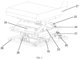
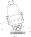
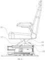
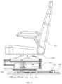
- the embodiment further provides a vibration isolation system for an automobile seat, adopting the active centrifugal force compensation control algorithm for the automobile seat, including a control assembly, a damping motor 22, a scissors mechanism 24, and an air spring 25, wherein the scissors mechanism 24 is rotatably arranged on a vehicle chassis 28, a seat body 27 is connected to the vehicle chassis 28 through the scissors mechanism 24, the damping motor 22 drives the scissors mechanism 24 to rotate, the air spring 25 is arranged on the scissors mechanism 24 and is used for buffering compression of the scissors mechanism 24 between the vehicle chassis 28 and the seat body 27, and the control assembly is electrically connected to the damping motor 22 and is used for adjusting rotation of the damping motor 22.
- the control assembly includes an inertia measurement unit 19, a controller 20, and a motor driver 21, wherein the inertia measurement unit 19 is electrically connected to the controller 20, the controller 20 is electrically connected to the motor driver 3, and the motor driver 21 is electrically connected to the damping motor 22.
- the vehicle chassis 28 is provided with a mounting base, and the scissors mechanism 24 is arranged on the mounting base through a rotating bearing 26.
- the scissors mechanism 24 includes a first connecting plate, a first scissors structure, a second scissors structure, and a second connecting plate, wherein the first connecting plate and the second connecting plate are connected through the first scissors structure and the second scissors structure, both ends of the first connecting plate are rotatably arranged on the mounting base through the rotating bearing 26, the second connecting plate is connected to the seat body 27, the damping motor 22 drives the first connecting plate to rotate to further drive the whole scissors mechanism 24 to rotate, so as to drive the seat body 27 to rotate, a driving end of the damping motor 22 is provided with a decelerator 23, and the first connecting plate is connected to the decelerator 23.
- the air spring 25 is arranged on the first connecting plate, a compression plate is connected between the first scissors structure and the second scissors structure, and the end, away from the air spring 25, of the first connecting plate is connected to the compression plate.
- the scissors mechanism 24 is further provided with a damper, through which a slow rebounding process can be achieved.
- the embodiment provides an active centrifugal force compensation control algorithm and an active and passive vibration isolation system in a complicated scenario.
- the algorithm is an active compensation algorithm for on-board equipment.
- the centrifugal force compensation control algorithm in the embodiment mainly includes a sensor fusion algorithm, trajectory planning, and PD control.
- the centrifugal force compensation control algorithm can achieve centrifugal force motion compensation in various complicated road conditions such as general turning, consecutive turning and S turning; the general turning is turning within 90 degrees, the consecutive turning is turning consecutively within 3 seconds in a same direction, and the S turning is turning consecutively within 3 seconds in different directions.
- An active and passive hybrid damping system mainly includes an IMU (Inertial Measurement Unit), a controller, a driver, a motor, a decelerator, a scissors mechanism, an air spring, a damper, and a seat.
- IMU Inertial Measurement Unit
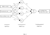
- the centrifugal force compensation control algorithm is mainly used for calculating an expected centrifugal force compensation angle when a vehicle takes a sudden turn. First, lateral acceleration, a normal angular velocity, and velocity information of a vehicle in an inertial space is acquired; high frequency noise of the acquired information is filtered by an FIR digital filter; then the two types of the filtered information are normalized by adopting the fusion algorithm; and finally, the excepted angle of the motor is acquired according to a mapping relation among a normalized value, a vehicle velocity, and a centrifugal force compensation angle. To guarantee the anti-interference performance of the system, can the centrifugal force compensation angle of the motor be calculated only when the absolute value of the normalized value is greater than a certain threshold.
- a trajectory planning algorithm is used for acquiring a maximum turning angle of the seat in the previous step first in the process that the seat rebounds slowly after the vehicle turns, and then planning a trajectory within a longer time by taking the maximum turning angle as an initial point and a zero angle as an endpoint, which aims to alleviate the discomfort when the seat rebounds rapidly.
- the PI control is used for tracking the angle of the damping motor, wherein by taking position information of a coder as a feedback signal, the motor keeps pace with the expected angle by adjusting a proportional integral parameter.
- the turning type detection module is arranged in the centrifugal force compensation control algorithm to differentiate general turning, consecutive turning, and S turning.
- the turning is the consecutive turning, plus and minus signs of the normalized value calculated by a sensor fusion algorithm are same within a short time; when the turning is the S turning, plus and minus signs of the normalized value calculated by the sensor fusion algorithm are opposite within the short time; and when the turning is the general turning, the normalized value appears only once within the short time.
- the embodiment provides an active inertia force compensation algorithm for on-board equipment, and a damping stretcher. Compared with the active inertia force compensation algorithm for on-board equipment in the embodiment 1 or 2, the acquired centrifugal force compensation angle and the control algorithm adopted are different in the active inertia force compensation algorithm for on-board equipment in the embodiment.
- the damping stretcher in the embodiment is applicable to an ambulance.
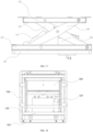
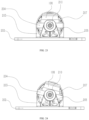
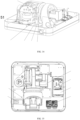
- the damping stretcher includes a base 4, a stretcher body 18, a sensor module 14, a control decision module 10, a passive damping module 16, a first rotary driving assembly, and a second rotary driving assembly.
- the base 4 is used for fixing the stretcher on a bottom plate of the ambulance, the sensor module 14 is arranged on the base 4 to acquire acceleration data and an attitude angle of the base 4, the acceleration data including a transverse acceleration and a longitudinal acceleration.
- the sensor module 14 can be an IMU module.
- the first rotary driving assembly is used for controlling a roll degree of freedom of the stretcher body 18, including a first motor 5, a first decelerator 6, and a first rotary shaft 7.
- the second rotary driving assembly is used for controlling a pitch degree of freedom of the stretcher body 18, including a second motor 11, a second decelerator 12, and a second rotary shaft 13.
- the first rotary driving assembly is fixedly arranged on the base 4, the second rotary driving assembly is fixedly arranged on the rotary shaft 7 of the first rotary driving assembly, the rotary shaft 7 of the first rotary driving assembly and a second rotary shaft 13 of the second rotary driving assembly are connected in series and orthogonally arranged, and the second rotary shaft 13 of the second rotary driving assembly is connected to the stretcher body 18 through the passive damping module, and the passive damping module 16 adopts an air spring.
- the active and passive hybrid damping stretcher for the ambulance includes a connecting frame 15, wherein the connecting frame 15 is fixedly connected to the second rotary shaft, the connecting frame 15 is movably connected to the stretcher body 18, and the passive damping module 13 is arranged between the stretcher body 18 and the connecting frame 15 and is used for providing a vertical passive degree of freedom of the upper table of the stretcher body 18.
- the stretcher body 18 is further provided with a locking device 17 for locking the ambulance stretcher that conveys a patient.
- the control decision module 10 is electrically connected to the sensor module 14, the first rotary driving assembly and the second rotary driving assembly, and the first rotary driving assembly and the second rotary driving assembly adjust the attitude of the seat body according to swing data.
- the damping stretcher further includes a fuse device 8, the fuse device 8 being electrically connected to the first rotary driving assembly and the second rotary driving assembly for overload protection; and a driver and a heat dissipating device 9 for driving the first rotary driving assembly and the second rotary driving assembly.
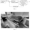
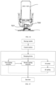
- FIG. 7 it shows a general control method for the active and passive hybrid damping stretcher for the ambulance, wherein the sensor module 14 acquires the transverse acceleration and the longitudinal acceleration in the inertial space of the ambulance in real time first, and the sensor data measured by the sensor is sent to the control decision module 10 through the communication module.
- the control decision module determines the target attitude of the upper table of the stretcher relative to the ambulance body by analyzing the sensor data. Therefore, the driver module controls the motor to rotate according to the control decision of the control decision module 10.
- the control decision module 10 is adjusted in real time according to an attitude angle of the stretcher body relative to the vehicle body acquired by the sensor module 14 in real time to track an expected trajectory precisely.
- the method includes the following steps:
- the step S3 includes the following steps:
- control method for the active and passive hybrid damping stretcher is specifically described below.
- the dynamics model and control targets As shown in FIG. 9 , it shows a model of the active and passive hybrid damping stretcher in the inertial coordinate system in the embodiment, where O i x i y i z i is the inertial coordinate system, O e x e y e z e is the compartment coordinate system of the ambulance, and O h x h y h z h is the coordinate system of the upper table of the stretcher, i.e., the coordinate system of the stretcher where the patient lies down.
- the upper platform move actively at the pitch degree of freedom to generate a compensation acceleration to counteract the impact.
- ⁇ hd arctan a x g ⁇ ⁇ e
- Equations (3) and (4) are the control expected targets of the two rotating mechanisms in the embodiment.
- the air bag in the embodiment can provide vertical passive damping when the ambulance drives on a bumpy pavement to reduce the vertical impact of the compartment on the human body.
- An MPC controller is an advanced control method, which generates a control output by predicting a dynamic model of the system.
- the MPC generates the control output by introducing a trajectory reference signal in the control system and predicting the system model, so as to control the reference trajectory of the system.
- FIG. 10 below gives a specific control logic of the MPC control algorithm on the two driving shafts of the stretcher in the embodiment.
- the MPC controller calculates the optimum control output by predicting the dynamic model of the system, so that the pitch angles ⁇ h and the roll angles ⁇ h of the two driving shafts approach to the expected trajectories ⁇ hd and ⁇ hd as far as possible respectively, and finally, the reference trajectory is precisely tracked.
- the tracking target function is designed first below according to the dynamics equation of the system, then the constraint condition is designed accounting for the structure and safety of the stretcher in the actual engineering, and finally, the optimum equation of the system is solved to obtain the control quality of the system, thereby precisely tracking the two driving shafts by the stretcher.
- the two rotating shafts in the embodiment intersect at one point. As the two degrees of freedom are decoupled, the two shafts can be controlled independently.
- u ⁇ is a driving force of the first rotary driving assembly
- u ⁇ is a driving force of the second rotary driving assembly
- J ( ⁇ h ) and J ( ⁇ h ) are respectively moment of inertia of the axes of motion of the first rotary driving assembly and the second rotary driving assembly
- C ( ⁇ h , ⁇ h ) and C ( ⁇ h , ⁇ h ) are Coriolis force, centrifugal force, and frictional force matrixes of the first rotary driving assembly and the second rotary driving assembly
- G ( ⁇ h ) and G ( ⁇ h ) are gravity matrixes of the first rotary driving assembly and the second rotary driving assembly
- the pitch angle ⁇ h and the roll angle ⁇ h of the stretcher body (18) are made accurate by controlling u ⁇ and u ⁇ , so that the control target is an expected tracking target, i.e., the formulae (3) and (4).
- the pitch angle ⁇ h and the roll angle ⁇ h are restrained.
- the pitch angle and the roll angle are respectively restrained at -15 degrees and 20 degrees, and the roll angle is restrained at ⁇ 20 degrees. Therefore, the constraints of the two active degrees-of-freedom robots in the motion process are: ⁇ ⁇ min k ⁇ ⁇ k ⁇ ⁇ max k ⁇ u min k ⁇ ⁇ u k ⁇ ⁇ u max k
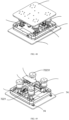
- the active and passive hybrid damping stretcher in the embodiment is mounted on a certain ambulance for actual road test, as shown in FIG. 12 .
- IMUs are respectively mounted in the compartment and on the upper table of the stretcher of the ambulance.
- the longitudinal and transverse damping efficiencies are calculated according to different measured values of the two IMUs. Meanwhile, the vertical passive damping effect is also calculated.
- Table 1 Longitudinal acceleration attenuation efficiency of the active and passive hybrid damping stretcher Longitudinal acceleration attenuation efficiency of the active and passive hybrid damping stretcher Tested vehicle velocity Upper table of stretcher Compartment bottom Attenuation efficiency Sudden braking at 20 km/h 1.457m/s 2 2.449m/s 2 40.51% Sudden braking at 2.241m/s 2 3.869m/s 2 42.08% 30 km/h Sudden braking at 40 km/h 2.282m/s 2 4.303m/s 2 46.97% Sudden braking at 50 km/h 2.941m/s 2 6.212m/s 2 52.66%
- Table 2 Transverse acceleration attenuation efficiency of the active and passive hybrid damping stretcher Transverse acceleration attenuation efficiency of the active and passive hybrid damping stretcher Tested vehicle velocity Upper table of stretcher Compartment bottom Attenuation efficiency Sudden turning at 20 km/h 0.924m/s 2 1.516m/s 2 39.05% Sudden turning at 30 km/h 1.537m/s 2 2.792m/s 2 44.95% Sudden turning at 40 km/h 1.976m/s 2 3.727m/s 2 46.98% Sudden turning at 50 km/h 2.213m/s 2 4.509m/s 2 50.92%
- the tested road condition is between the grade B pavement and a grade C paved, and the ambulance travels respectively at average velocities of 20 km/h, 30 km/h, 40 km/h, and 50 km/h.
- the damping result are shown in Table 3: Table 3 Vertical acceleration attenuation efficiency of the active and passive hybrid damping stretcher Vertical acceleration attenuation efficiency of the active and passive hybrid damping stretcher Tested vehicle velocity Average fluctuation amplitude of upper table of stretcher Average fluctuation amplitude of compartment bottom Attenuation efficiency Average velocity of 20 km/h 8.15% g 11.5% g 29.13% Average velocity of 30 km/h 8.21% g 12.2% g 32.70% Average velocity of 40 km/h 8.22% g 12.5% g 34.24% Average velocity of 50 km/h 8.3% g 12.6% g 34.13%
- the average fluctuation amplitude of the vertical acceleration is about 12% of the gravitational acceleration, and without the passive damping in the embodiment, the average fluctuation amplitude of the vertical acceleration decreases to about 8%, with the attenuation efficiency being about 30%, which has a comparatively apparent effect.
- the technical solution of the embodiment greatly reduces the longitudinal acceleration impact caused by sudden acceleration and sudden deceleration of the ambulance, with the maximum damping efficiency reaching over 50%.
- the technical solution of the embodiment greatly reduces the transverse acceleration impact caused by sudden turning of the ambulance, with the maximum damping efficiency reaching over 50%.
- the technical solution of the embodiment further reduces the impact caused by the vertical acceleration on a basis that the vehicle suspension has vertical damping under a condition that the vehicle travels on the bumpy road, with the maximum damping efficiency reaching over 30%.
- a seat damping structure provided in the embodiment adopts the active compensation algorithm for an inertia force of on-board equipment in the embodiment 3.
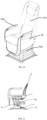
- the seat damping mechanism provided in the embodiment includes a passive damping mechanism 101, an active stabilizing mechanism 201, and a rotary slip anti-impact mechanism 301 arranged from top to bottom in sequence, and the seat surface (001) is mounted above the passive damping mechanism 101.
- the passive damping mechanism 101 drives the seat surface 001 to be compressed or released in a direction perpendicular to the seat surface 001, so as to absorb a force in the direction perpendicular to the seat surface 001.
- the active stabilizing mechanism 201 drives the passive damping mechanism 101 and the seat surface 001 to perform a roll motion, so as to compensate the centrifugal force.
- the rotary slip anti-impact mechanism 301 drives the active stabilizing mechanism 201, the passive damping mechanism 101, and the seat surface 001 to slide in a horizontal plane, so as to absorb the inertia force.
- the seat surface 001 in the embodiment can be matched with most automobile seats on the market.
- the seat surface 001 performs a reciprocating motion in a direction vertical to the seat surface 001, thereby providing damping buffer to the seat in the vertical direction.
- the active stabilizing mechanism 201 performs a roll motion at a corresponding angle by collecting displacement data of the chassis of the vehicle body, so as to compensate the centrifugal force.
- the rotary slip anti-impact mechanism 301 slides in a front-back direction of the seat to absorb the inertia force. Therefore, the riding comfort and safety of the passengers are improved.
- the passive damping mechanism 101 includes a damping seat mounting plate 102, a damping base 103, a connecting plate 104, an internal intersecting arm 105, an external intersecting arm 106, an elastic assembly, a roll shaft 109, and a rotating pin shaft 110.
- the internal intersecting arm 105 and the external intersecting arm 106 are arranged between the damping seat mounting plate 102 and the damping base 103, a middle portion of the internal intersecting arm 105 is rotatably connected to a middle portion of the external intersecting arm 106 through the rotating pin shaft 110, a lower end of the internal intersecting arm 105 is rotatably connected to the damping base 103 through the rotating pin shaft 110, an upper end of the internal intersecting arm 105 is slidably connected to the damping seat mounting plate 102 through the roll shaft 109, a lower end of the external intersecting arm 106 is slidably connected to the damping base 103 through the roll shaft 109, and an upper end of the external intersecting arm 106 is rotatably connected to the damping seat mounting plate 102 through the rotating pin shaft 110.
- the elastic assembly acts on the internal intersecting arm 105 and/or the external intersecting arm 106, and the elastic action direction of the elastic assembly is the direction perpendicular to the seat surface 001.
- the elastic assembly includes a magnetorheological damper 107 and an elastic part 108, the elastic action direction of the elastic part 108 is the direction perpendicular to the seat surface 001, the magnetorheological damper 107 acts on the internal intersecting arm 105 and/or the external intersecting arm 106, and the elastic action direction of the magnetorheological damper 107 intersects with the elastic action direction of the elastic part 108.
- the elastic part 108 in the application includes an air spring and can also be a gas spring or springs in other forms.
- the middle portions of the damping seat mounting plate 102 and the damping base 103 are connected through scissors cross structures of the internal intersecting arm 105 and the external intersecting arm 106, and the elastic part 108 and the magnetorheological damper 107 act on opening and closing of the scissors cross structures.
- the magnetorheological damper 107 can make the elastic part 108 compress and rebound more flexibly and comfortably.
- the damping seat mounting plate 102 and the damping base 103 opens and closes up and down synchronously with compression and rebound of the elastic part 108, and finally, the seat surface 001 performs a corresponding up-down vertical motion with fluctuation and bump of the pavement to counteract the fluctuation and bump.
- the magnetorheological damper 107 When the vehicle passes through a flat pavement such as an overpass and an expressway, the magnetorheological damper 107 will be controlled by the master control module 209 to raise the current, so that the damping force is adjusted to the maximum extent. Thus, the scissors cross structures are locked to close the vertical up-down motion, so that the unnecessary up-down fluctuation of the seat surface 001 on the flat pavement is reduced.
- the damping base 103 is connected to the active stabilizing mechanism 201 through fastening bolts and the connecting plate 104.
- the active stabilizing mechanism 201 includes a stabilizing mechanism mounting plate 202, an active mounting seat 203, a roll output plate 204, a bearing pedestal 205, a driving assembly, a limiting buffer pad 208, a master control module 209, and a roll bearing 210.
- the driving assembly includes a roll motor 206 and a decelerator 207.
- the roll output plate 204 and the driving assembly both are mounted on the stabilizing mechanism mounting plate 202.
- An output shaft of the driving assembly is horizontally arranged, the roll output plate 204 is tightly connected to the output shaft of the driving assembly, and the passive damping mechanism 101 is mounted on the roll output plate 204 through fastening bolts and the connecting plate 104.
- the master control module 209 collects attitude data of the vehicle body, and controls the driving assembly through the attitude data of the vehicle body to drive the roll output plate 204 to rotate.
- the active stabilizing mechanism further includes a limiting buffer pad 208, and the limiting buffer pad 208 defines a rotating range of the roll output plate 204 to be ⁇ 30°.
- the active mounting seat 203 on the stabilizing mechanism mounting plate 202 is used for fixing the roll motor 206 and the decelerator 207.
- One end of the roll output plate 204 is mounted on the output shaft of the decelerator 207, and the other end of the roll output plate 204 is supported by the bearing pedestal 205 and the roll bearing 210.
- the roll motor 206 acts to obtain data operated by the algorithm by collecting vehicle body attitude data by the attitude sensor in the master control module 209, the data is sent to the motor driver in the master control module 209 to drive the roll motor 206 to perform corresponding work.
- the output of the roll motor 206 will be sent to the decelerator 207, so that the decelerator 207 and the roll output plate 204 both perform corresponding roll motions at the same time.
- the roll motion in the application is rotation of the roll output plate 204 around the output shaft of the decelerator 207.
- the axial direction of the output shaft of the decelerator 207 is parallel to the front-back direction of the seat.
- the maximum motion angle of the roll output plate 204 can be limited by adjusting the position of the limiting buffer pad 208, and the maximum motion angle can be +-30°.
- the roll output plate 204 and the connecting plate 104 are interconnected through fastening bolts, so that the passive damping mechanism 101 and the seat surface 001 both perform corresponding roll motions synchronously.
- the centrifugal force to the passengers when the vehicle turns is compensated through the roll motion of the seat surface 001, so that the passengers are in a relative comfortable state all along.
- the rotary slip anti-impact mechanism 301 includes a vehicle mechanism base 302, a seat sliding bottom plate 303, a position adjusting assembly, and a buffer assembly.
- the seat sliding bottom plate 303 is slidably mounted on the vehicle mechanism base 302, the position adjusting assembly adjusts the relative positions between the seat sliding bottom plate 303 and the vehicle mechanism base 302, and the buffer assembly inhibits the relative positions between the seat sliding bottom plate 303 and the vehicle mechanism base 302.
- the position adjusting assembly includes two ball screw 309 structures, and the two ball screw 309 structures are parallelly mounted on two opposite sides of the seat sliding bottom plate 303 respectively and slidably connected to the overall mechanism base 302.
- the ball screw 309 structure includes a lead screw tail stock 306, a structural reinforcing bar 308, a ball screw 309, a seat sliding motor 310, a sliding motor base 311, a nut mounting seat 316, a bottom slide block 317, a coupling 324, a lead screw nut 325, a lead screw bearing 327, a seat sliding slide block 326, and a sliding sleeve 323.
- the lead screw tail stock 306 and the sliding motor base 311 are mounted on the overall mechanism base 302 through the structural reinforcing bar 308, the ball screw 309, the seat sliding motor 310, the bottom slide block 317, and the coupling 324.
- the lead screw tail stock 306, the structural reinforcing bar 308, the ball screw 309, the seat sliding motor 310, the sliding motor base 311, the bottom slide block 317, and the coupling 324 can slide front and back synchronously in a chute of the overall mechanism base 302.
- the seat sliding bottom plate 303, the nut mounting seat 316, the lead screw nut 325, and the seat sliding slide block 326 are mounted on the structural reinforcing bar 308 and the ball screw 309; when the seat sliding motor 310 rotates, it drives the coupling 324 and the ball screw 309 to rotate synchronously; the lead screw nut 325 will displace due to rotation of the ball screw 309; by matching the seat sliding slide block 326 with the sliding sleeve 323, the displacement will drive the whole active stabilizing mechanism 201, the passive damping mechanism 101, and the seat surface 001 to displace together, which means a function of adjusting the seat front and back.
- the motor base connecting plate 318 connects the sliding motor bases 311 in the two ball screw 309 structures through screws as a whole.
- the buffer assembly includes a plurality of buffer parts, and the direction of the action force of any one buffer part is parallel to a moving direction of each of the ball screw 309 structures.
- One end of any one buffer part is fixedly connected to the overall mechanism base 302 and the other end thereof is fixedly connected to the seat sliding bottom plate 303 and/or the position adjusting assembly.
- the buffer assembly includes a gas spring tail stock 307, a damper mounting seat 312, a buffer damper 313, a gas spring fixing seat 314, and a buffer gas spring 315.
- the buffer parts in the application are preferably the buffer damper 313 and the buffer gas spring 315.
- the buffer gas spring 315 is arranged on each of two opposite sides of the seat sliding bottom plate 303. Any buffer gas spring 315 is fixedly connected to the overall mechanism base 302 through the gas spring fixing seat 314 and the gas spring tail stock 307. The movable end of the buffer gas spring 315 is connected to the corresponding sliding motor base 311.
- the buffer damper 313 is mounted through the damper mounting seat 312, one end of the buffer damper 313 is in contact with the overall mechanism base 302, and the other end of the buffer damper 313 is in contact with the motor base connecting plate 318.
- the sliding motor base 311 will be subjected to resistance of the buffer damper 313 and the buffer gas spring 315 during sliding, and the buffer damper 313 and the buffer gas spring 315 will also be compressed as the sliding motor base 311 slides.
- the rotary slip anti-impact mechanism 301 includes a rotating assembly, wherein the rotating assembly includes a seat rotating bottom plate 304, a rotary locking hook 305 and a locking hook top plate 319, the seat rotating bottom plate 304 is rotatably connected to the seat sliding bottom plate 303, and the locking hook top plate 319 acts on the rotary locking hook 305 to lock the seat rotating bottom plate 304 and the seat sliding bottom plate 303 or separate the lock the seat rotating bottom plate 304 and the seat sliding bottom plate 303.
- the rotating assembly further includes a base tray 320, a seat rotating bearing 321, and a seat turnplate tightening nut 322.
- a seat rotating bottom plate 304, a rotary locking hook 305, the base tray 320, the seat rotating bearing 321, and the seat turnplate tightening nut 322 are also mounted on the seat sliding bottom plate 303.
- the rotary locking hook 305 bounces off, the seat rotating bottom plate 304 is in an unlocked state and can rotate arbitrarily.
- the seat surface 001 of the seat rotates synchronously due to a series relation.
- the seat surface 001 of the seat will slide along the traveling direction of the vehicle as a result of inertia.
- the sliding velocity is slowed down due to resistance of the buffer gas spring 315 and the buffer damper 313, so that there is a forward buffer distance for the seat surface 001 when the vehicle takes emergency braking or is impacted finally. Therefore, the body of the passenger will not displace forwards relative to the seat surface 001 of the seat as a result of emergency braking. Instead, the seat surface 001 of the seat, together with the passenger, displaces, so that the probability that the passenger is injured is reduced when the vehicle takes emergency braking or is impacted.
- the embodiment further provides a vehicle, adopting the above damping and stabilizing anti-impact structure for the seat, the damping and stabilizing anti-impact structure for the seat being mounted on a vehicle body bottom plate.
- the damping and stabilizing anti-impact structure for the seat is fixedly connected to the vehicle body bottom plate through the overall mechanism base 302.
- the overall mechanism base 302 in the application can be mounted in a fit manner on most passenger vehicles and commercial vehicles on the market.
- the embodiment absorbs the force in the direction perpendicular to the seat surface through the passive damping mechanism to achieve damping, compensates the centrifugal force through the active stabilizing mechanism to achieve stabilizing, and absorbs the inertia force through the rotary slip anti-impact structure to achieve impact resistance.
- the embodiment features compact structure and small occupied space while achieving damping, stabilizing and anti-impact functions, which contributes to improving the riding comfort and safety of the passenger;
- the embodiment provides a damping device, adopting the active compensation algorithm for an inertia force of on-board equipment in the embodiment 3.
- the movable platform 32 is usually arranged at the bottom of the damped target.
- the damped target can be either a seat of an automobile traveling or any equipment with sway, and the like in the moving process such as a seat on an airplane.
- the bottom platform 29 is correspondingly fixed on a floor inside a carrier such as the automobile or the airplane, and the bottom plate of the automobile or the airplane, and the like can also be directly used as the corresponding bottom platform 29.
- the automobile will generate multidimensional vibration in the traveling process, for example linear vibration in the front-back direction during braking, and in this case, a motion acceleration in the pitch direction will be generated on the passenger, so that the passenger pitches front and back.
- the active pitch damping device starts the pitch motor 30 to rotate to provide a reverse motion compensation to the movable platform 32, so that the passenger may not swing front and back.
- the roll motor 34 needs to provide a centripetal acceleration in the left-right direction for reverse motion compensation.
- the pitch motor 30 when it rotates, it drives the active pitch damping device to rotate integrally and drives the output support 43 arranged on the active roll damping device to move.
- the guide pillar 41 when there is backward pitching, the guide pillar 41 will incline backwards, and in this case, as the active pitch damping device will provide the guide pillar 41 a forward force through the output support 43, the attitude of the guide pillar 41 is maintained, and the attitude of the movable platform 32 is maintained by maintaining the attitude of the guide pillar 41.
- the roll motor 34 drives the active roll damping device to rotate and provides the guide pillar 41 with a rightward force through the output support 43, so that the attitude of the guide pillar 41 is maintained, and the attitude of the movable platform is maintained by maintaining the attitude of the guide pillar 41.
- the base is provided with a guide pillar support 40 for mounting the guide pillar 41.
- the two motors are controlled to rotate, and the active compensation motion is transferred to the movable platform 32 through the damping output device.
- the motors in the roll direction and the pitch direction are respectively arranged for active compensation, and output through the guide pillar 41, so that left-right and front-back sway is reduced, the high frequency vibration of the same platform is reduced, and thus, the stability of the damped target is improved.
- the active pitch damping device further specifically includes a pitch decelerator support 31, a pitch decelerator 47, a pitch motion output support 33, and a bearing pedestal 46;
- the pitch decelerator support 31 is fixed on the bottom platform 29; one end of the pitch decelerator support 31 is connected to the pitch motor 30 and the other end thereof is connected to the pitch decelerator 47; one end of the pitch motion output support 33 is connected to the pitch decelerator 47, and the other end thereof is connected to the bearing pedestal 46; and the bearing pedestal 46 is fixed on the bottom platform 29;
- the motor itself is not usually a high horse power motor but a low horse power servo motor
- the motor features relatively small twisting force, so a corresponding decelerator needs to be arranged to output a large twisting force.
- a fixed bearing pedestal 46 and the pitch decelerator support 31 are fixed on the bottom platform 29, one end of the pitch decelerator 47 is connected to the pitch motor 30 and the other end thereof is connected to the pitch motion output support 33, the formed whole is arranged between the fixed bearing pedestal 46 and the pitch decelerator support 31 in a bestriding manner, and the active roll damping device is mounted through the roll device mounting hole.
- the side surface of the pitch motion output support 33 is T-shaped, the T-shaped structure of the pitch motion output support 33 is provided with a plurality of mounting holes including a pitch decelerator mounting hole 58 formed in the bottom of the pitch mounting base 68, and the pitch motion output support 33, the pitch decelerator 47, and the pitch motor 30 form a whole through the mounting hole. Therefore, the active compensation motion of the pitch motor 30 is conducted to the pitch motion output support 33, so that the compensation is transferred to the output support 43 through the active roll damping device arranged on the pitch motion output support 33.
- the roll device mounting hole specifically includes a roll decelerator mounting hole 61 and a roll motor base mounting hole 63 respectively used for mounting the roll decelerator and the roll motor, and a bearing pedestal mounting hole 62 is formed for mounting the bearing pedestal 34.
- the active pitch damping device further includes pitch anti-collision blocks 49 and a pitch anti-collision pad 48;
- the pitch anti-collision pad 48 is mounted on the bottom platform 29 and is located below the pitch decelerator support 31;
- the pitch anti-collision blocks 49 are mounted on both sides of the pitch motion output support 33, and rotate along with rotation of the active pitch damping device; and when the pitch anti-collision blocks 49 impact to the pitch anti-collision pad 48 in a rotating process, the pitch anti-collision pad 48 is matched with the pitch anti-collision blocks 49 to limit further rotation of the active pitch damping device.
- the pitch anti-collision pad 48 is arranged on the bottom platform 29, and the corresponding anti-collision blocks 49 are arranged in positions corresponding to both sides of the pitch motion output support 33, so that in the rotating process of the pitch motion output support 33, the rotating range is limited between two collision points between the anti-collision blocks 49 and the pitch anti-collision pad 48.
- the pitch motion output support 33 is provided with pitch anti-collision mounting holes 59 which are respectively formed in both sides of the pitch motion output support 33 on the axis taking the inverted trapezoidal T-shaped structure of the pitch mounting base 68 as the longitudinal structure for mounting the pitch anti-collision blocks 49.
- the active roll damping device further specifically includes a roll decelerator 45 and a roll motion output support 43, wherein one side of the roll motion output support 43 is connected to the output support 43 and the other side thereof is connected to the roll decelerator 45; and one side of the roll decelerator 45 is connected to the roll motion output support 43 and the other side thereof is connected to the pitch motion output support 33;
- the roll motion output support 43 specifically includes a mounting base and an output connecting block 70, wherein one side of the mounting base is connected to the output connecting block 70 and the other side thereof is connected to the roll decelerator 45; and one end of the output connecting block 70 is connected to the mounting base and the other end thereof is connected to the output support 43.
- the roll motion device arranged on the pitch motion output support 33 will perform a pitch motion along with the pitch motion output support 33 and outputs motion through the roll decelerator 45 because the motor 34 itself is not usually a high horse power motor but a low horse power servo motor, the motor features relatively small twisting force, so a corresponding decelerator needs to be arranged to output a large twisting force.
- the mounting base arranged on the roll decelerator 45 performs a rotating motion along with the roll decelerator 45, drives the output connecting block 70 to rotate, and further acts the motion on the output support 43 for motion compensation. Meanwhile, the roll decelerator mounting hole 67 is formed in the mounting base for mounting the roll decelerator.
- the active roll damping device includes a damper 44, wherein one end of the damper 44 is connected to the output connecting block 70 and the other end thereof is connected to the movable platform 32 through a revolute pair.
- the damping efficiency can be improved as far as possible, very small friction and air resistance in the system can be compensated, and the frequency response can be improved greatly.
- the damper 44 is mounted between the output connecting block 70 and the movable platform 32; the lower end of the damper 44 is fixed to the output connecting block 70, and is fixed through a damper mounting hole 66 formed in the output connecting block 70; the upper end of the damper is connected to the movable platform 32 through the revolute pair, and the axis of the revolute pair is parallel to the rotating axis of the pitch motor 30; and as the axis of the revolute pair is parallel to the rotating axis of the pitch motor 30, in the moving process, break of the revolute pair due to motion of the pitch motor 30 will be avoided.
- the roll motion output support further includes a roll anti-collision block 51 and a roll anti-collision pad 52, wherein the roll anti-collision pad 52 is arranged on a side, adjacent to the damping output device, of the pitch motion output support 33; the roll anti-collision block 51 is arranged on a side surface of the mounting base, and rotates along with rotation of the roll motor 34; when the roll anti-collision block 51 impacts to the roll anti-collision pad 52 in a rotating process, the roll anti-collision pad 52 limits further rotation of the active roll damping device.
- the roll anti-collision pad 52 is arranged on the side, adjacent to the roll anti-collision pad 52, of the pitch motion output support 33, and the corresponding anti-collision blocks 51 are arranged in positions corresponding to the side surface of the mounting base, so that in the rotating process of the output support 43, the rotating range is limited between two collision points between the anti-collision blocks 51 and the pitch anti-collision pad 52.
- the roll anti-collision mounting holes 64 are symmetrically formed in the side surface and the top surface of the mounting base by taking the output connecting block 70 as an axis of symmetry, and the roll anti-collision pad mounting hole 57 is formed in the side, adjacent to the output support 43, of the pitch mounting base 68 of the pitch motion output support 33 for mounting the roll anti-collision pad 52. Meanwhile, a roll limiting switch reserved hole 60 is reserved for reserving a refitting position for a limiting switch in the future.
- axis of rotation of the pitch motor 30 perpendicularly intersects with axis of rotation of the roll motor 34 all along.
- a ball guide sleeve 42 is arranged between the output support 43 and the guide pillar 41; and the output support 43 moves up and down along the guide pillar 41 through the ball guide sleeve 42.
- the ball guide sleeve 42 is arranged between the output support 43 and the guide pillar 41, so that the output support 43 and the guide pillar 41 are not rigidly fixed but the output support 43 moves up and down on the guide pillar 41. Therefore, the guide pillar 41 is prevented from breaking due to rigid fixation.
- both ends of the guide pillar 41 are provided with limiting bosses, and when the output support 43 impacts to the limiting bosses in the up-down moving process, the limiting bosses limit further movement of the output support 43 towards an edge of the guide pillar 41.
- the embodiment provides a damping device, adopting the active compensation algorithm for an inertia force of on-board equipment in the embodiment 3.
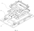
- the damping device provided by the embodiment includes: a movable platform 32 for being connected to a damped target; a bottom platform 29, wherein the active pitch damping device is fixed on the bottom plate 29; the active pitch damping device includes a pitch motor 30; an active roll damping device, arranged on the active pitch damping device and driven by the pitch motor 30 to rotate around a rotating shaft of the pitch motor 30, wherein the active roll damping device includes a roll motor 34 for driving the active roll damping device to rotate; a damping output device, wherein the damping output device specifically includes a guide pillar 41 and an output support 43, the output support 43 is fixed on the active roll damping device, and the output support 43 is internally provided with a guide hole 65; and the guide pillar 41 passes through the guide hole 65 and is connected to the movable platform 32.
- the damping device further includes a passive damping device, specifically including an air spring 39, wherein one end of the air spring 39 is arranged on the movable platform 32 and the other end thereof is arranged on the bottom platform 29; the bottom platform 29 is further provided with an air pump 35, and is connected to the air spring 39 through a gas pipeline 50 for maintaining a pressure of the air spring 39; there are four air springs 39; and the air springs 39 are respectively arranged at four corners of the bottom platform 29.
- a passive damping device specifically including an air spring 39, wherein one end of the air spring 39 is arranged on the movable platform 32 and the other end thereof is arranged on the bottom platform 29; the bottom platform 29 is further provided with an air pump 35, and is connected to the air spring 39 through a gas pipeline 50 for maintaining a pressure of the air spring 39; there are four air springs 39; and the air springs 39 are respectively arranged at four corners of the bottom platform 29.
- the passive damping device shall be arranged while active damping is arranged to control high frequency vertical vibration.
- passive damping is usually achieved by using the four air springs 39 distributed at four corners of the bottom platform 29 and the movable platform 32, and the air pump 35 is connected through the gas pipeline 50 extending to the air springs 39, so that the internal air pressure in the air springs 39 is maintained.
- the air springs 39 located at the four corners of the bottom platform 29 deform correspondingly as the buffer pads to buffer the movable platform 32, so as to eliminate influence of the high frequency vertical vibration on the movable platform 32.
- the air springs 39 will play a passive damping role, so that influence of the high frequency vertical vibration on the movable platform 32 is alleviated.
- the passive damping device further includes an air spring bottom pillar 38 arranged on the bottom platform 29 for fixedly connecting the air spring 39 and the bottom platform 29; and the gas pipeline 50 is connected to the air spring 39 through the air spring bottom pillar 38.
- the bottom platform 29 is provided with an air spring bottom pillar mounting hole 56.
- the bottom platform 29 is provided with an air spring 39 basal pillar mounting hole 10; the air spring bottom pillar 38 is mounted on the bottom platform 29 through the air spring 39 basal pillar mounting hole 10, and the gas pipeline 50 enters the air spring bottom pillar 38 from the air spring 39 basal pillar mounting hole 10 formed in the bottom platform 29 and is then connected to the air spring 39 through the air spring bottom pillar 38, so that the air pump 35 can inflate the air spring 39.
- the air spring 39 is internally provided with an air pressure sensor, the air pressure sensor is electrically connected to an automatic air pressure inflating control panel 36; when the air pressure sensor detects that the air pressure in the air spring 39 is lower than a preset air pressure, the automatic air pressure inflating control panel 36 controls the air pump 35 to inflate the air spring 39 through the gas pipeline 50.
- the air spring 39 is internally provided with the air pressure sensor for detecting the air pressure in the air spring 39 and transmitting the air pressure to the automatic air pressure inflating control panel 36, so that the air pump 35 is controlled through the automatic air pressure inflating control panel 36.
- the automatic air pressure inflating control panel 36 sends out an inflating command to control the air pump 35 to inflate a high pressure gas into the air spring 39 through the gas pipeline 50; and the high pressure gas is inflated into the air spring 39 through the gas pipeline 50 by passing through the air spring bottom pillar 38, so that the air pressure in the air spring 39 is maintained at a target value.
- the embodiment provides a damping device, adopting the active compensation algorithm for an inertia force of on-board equipment in the embodiment 3.
- the damping device provided by the embodiment includes: a movable platform 32 for being connected to a damped target; a bottom platform 29, wherein the active pitch damping device is fixed on the bottom plate 29; the active pitch damping device includes a pitch motor 30; an active roll damping device, arranged on the active pitch damping device and driven by the pitch motor 30 to rotate around a rotating shaft of the pitch motor 30, wherein the active roll damping device includes a roll motor 34 for driving the active roll damping device to rotate; a damping output device, wherein the damping output device specifically includes a guide pillar 41 and an output support 43, the output support 43 is fixed on the active roll damping device, and the output support 43 is internally provided with a guide hole 65; and one end of the guide pillar 41 is connected to the bottom platform 29, and the other end thereof passes through the guide hole 65 and is connected to the movable platform 32.
- the damping device further includes an attitude sensor 53, a master control panel 37, and a motor driver 54; wherein the attitude sensor 53 is electrically connected to the master control panel 37 and is configured to detect the acceleration of the damped target to generate an acceleration signal and transmit the acceleration signal to the master control panel 37, and the master control panel 37 controls the motor driver 54 according to the acceleration signal to drive the pitch motor 30 and the roll motor 34 to operate.
- the bottom platform 29 is provided with the attitude sensor 53, the master control panel 37, and the motor driver 54.
- the attitude sensor 53 is usually achieved by directly using the acceleration sensor and is configured to detect the acceleration of the damped target, and the master control panel 37 achieves driving control of the motor according to the acceleration.
- the bottom platform is provided with a power interface 55 for supplying power to all electrical equipment and providing 48V and 12V voltages.
- the master control panel 37 when the master control panel 37 considers that it is necessary to compensate the data transmitted by the attitude sensor 53 to the master control panel 37, the master control panel 37 sends out a corresponding driving signal to the motor driver 54. Controlled by the driving signal, the motor driver 54 sends out motion signals to the pitch motor 30 and the roll motor 34, so as to control operations of the pitch motor 30 and the roll motor 34.
- the active damping direction is detected by the attitude sensor 53, so that the damping efficiency is effectively improved, and the comfort in the damping process is enhanced.
- the master control board 37 controls the motor driver 54 according to the linear acceleration to drive operation of the pitch motor 30.
- the attitude sensor 53 when the attitude sensor 53 detects the linear acceleration, it indicates braking or accelerating conditions.
- the automobile will generate linear vibration in the front-back direction during braking and accelerating, and in this case, it will generate the motion acceleration to the passenger in the pitch direction, so that the passenger pitches front and back.
- the active pitch damping device starts the pitch motor 30 to rotate to provide a reverse motion compensation to the movable platform 32, so that the passenger may not swing front and back.
- the master control panel 37 controls the motor driver 54 according to the centripetal acceleration to drive operation of the roll motor 34.
- the attitude sensor 53 detects the centripetal acceleration, it indicates sudden turning, and the like.
- the automobile takes a sudden turn, it will generate linear vibration in the left-right direction, and in this case, the roll motor 34 needs to provide a linear acceleration in the left-right direction for reverse motion compensation, so that the passenger may not swing left and right.
- the present invention further provides a seat, including a seat body and the damping device according to the embodiments 5-7.
- the seat body is fixed on a movable platform 32 of the damping device.
- the damping device is usually applied to the seat to compensate vibration of the seat.
- the seat can be arranged either on an automobile or an airplane, and can be adjusted according to an actual demand.
- the present invention further provides an automobile, using the above seat.
- the seat is usually applied to the automobile for enhancing the comfort level of the automobile passenger.
- the attitude sensor 53 detects the linear acceleration, it indicates braking or accelerating conditions.
- the automobile will generate linear vibration in the front-back direction during braking and accelerating, and in this case, it will generate the motion acceleration to the passenger in the pitch direction, so that the passenger pitches front and back.
- the active pitch damping device starts the pitch motor 30 to rotate to provide a reverse motion compensation to the movable platform 32, so that the passenger may not swing front and back.
- the attitude sensor 53 detects the centripetal acceleration, it indicates sudden turning, and the like.
- the roll motor 34 needs to provide a centripetal acceleration in the left-right direction for reverse motion compensation, so that the passenger may not swing left and right.
- the embodiment provides an active damping seat, adopting the damping device in any one embodiment of the embodiments 5-7, and adopting the active compensation algorithm for an inertia force of on-board equipment in the embodiment 3.
- the active damping seat in the preferred embodiment includes a seat base 71 and a self-balancing damping device 72, wherein the seat base 71 is mounted on the self-balancing damping device 72; the self-balancing damping device 72 is applicable to mounting carrying equipment, including a sensing module 721, a damping device 722, and a control module 723; the sensing module 721 is configured to acquire motion data of the carrying equipment,; the control module 723 is configured to receive the data of the sensing module 721 and to control motion parameters of the damping device 722; and the damping device 722 includes a first rotating assembly 7221 and a second rotating assembly 7222, wherein the first rotating assembly 7221 is applicable to being mounted on the carrying equipment, the second rotating assembly 7222 is mounted at a driving end of the first rotating assembly 7221, and the first rotating assembly 7221 and the second rotating assembly 7222 are capable of driving the seat 71 to perform roll and pitch motions; when the first rotating assembly 7221 drives the seat base 71 to perform
- the seat base 71 in the embodiment includes a seat back 711, an armrest 712, and a rubber ring 713.
- the seat back 711 is convenient for a driver to lean against, so that the comfort and the wrapping performance of the active damping seat are improved.
- the armrest 712 is convenient for the driver to place arms and place some objects as well.
- the self-balancing damping device 72 is placed in the rubber ring 713, the rubber ring is capable of being hermetic and waterproof, and the rubber ring 713 shrinks with motion of the self-balancing damping device 72, and is difficultly damaged.
- the sensing module 721 is mounted in the self-balancing damping device 72 to acquire motion data of the carrying equipment; the control module 723 can control the first rotating assembly 7221 and the second rotating assembly 7222 to operate according to the motion data acquired by the sensing module 721 so as to control the degrees of freedom of motions in roll and pitch directions of the seat base 71, i.e., to provide a reverse action force in the inclined direction of the seat base 71, so that the seat base 71 is kept stable, thereby achieving a self-balancing damping effect.
- the motion data of the carrying equipment can specifically include, for example, vehicle velocity, displacement, acceleration, and the like.
- the active damping device 2 is assembled on the seat base 71 to form a self-balancing damping system, which effectively damps the seat base 71 in a high frequency low amplitude environment and a low frequency high amplitude environment, thereby achieving the self-balancing damping effect. Therefore, the seat base 71 is kept in a stable operating state all along.
- the carrying equipment can be, for example, any traffic tool such as a vehicle, a ship or a yacht.
- the active damping seat provided in the embodiment can be applied to a driver's cab of the any traffic tool, which is not limited herein.
- the carrying equipment provided in the embodiment is specifically explained and described by taking the vehicle as an example.
- the sensing module 721 can collect motion data of the vehicle in real time and actively control the first rotating assembly 7221 and the second rotating assembly 7222 of the damping device 722 to operate according to the motion data; the first rotating assembly 7221 and the second rotating assembly 7222 are jointed and matched in an assisted manner to control the degrees of freedom of motions in the roll and pitch directions of the seat base 71, i.e., to provide the reverse action force in the incline direction of the seat base 71 relative to the vehicle. The two forces are counteracted, so that the seat base will not change in attitude synchronously with the vehicle.
- the seat base is ensured to be kept in a stable state all along, so that it can be ensured that the active damping seat is capable of being kept stable all along.
- the sensing module 721 when the carrying equipment is subjected to vibration, the sensing module 721 will measure motion data such as an attitude angle deviation and an acceleration variable quantity of the seat base 71 in a balanced state, and transfers the motion data in real time to the control module 723.
- the control module 723 can calculate parameters such as velocity, displacement, and acceleration needed by the first rotating assembly 7221 and the second rotating assembly 7222 to make the seat base 71 be kept balanced based on an active and passive damping self-balancing algorithm of a series-parallel robot, and performs corresponding actions according to commands of the control module 723, so as to achieve self-balancing of the seat base.
- first rotating assembly 7221 and the second rotating assembly 7222 both can be driven by the motors independently, wherein the second rotating assembly 7222 can be driven by either the motors or the first rotating assembly 7221 as it is mounted at the driving end of the first rotating assembly 7221. Therefore, when only the roll or pitch motion in the single direction is needed, the second rotating assembly 7222 can be directly driven by the motor to achieve the reverse motion of the seat base 71, so that it is ensured that the seat base 71 is kept stable all along.
- the first rotating assembly 7221 and the second rotating assembly 7222 are rotated in a combined manner according to the commands of the control module 723 to provide a reverse equivalent action force relative to the inclined direction of the vehicle, thereby ensuring that the seat base 71 is stable all along.
- the above damping device is without the passive damping device.
- the embodiment further provides a damping seat with a passive damping device, as shown in FIGS. 46-49 .
- the damping device 722 further includes an elastic damping assembly 7223, wherein a top end of the elastic damping assembly 7223 is mounted on the seat base 71, and a bottom end thereof is fixed to a mounting plane of the self-balancing damping device 72 for applying an action force to the seat 1 in the height direction.
- the mounting plane of the self-balancing damping device 72 can be either the carrying equipment or a bottom surface of the active damping seat.
- the mounting plane of the self-balancing damping device 72 is the bottom surface of the active damping seat, the self-balancing damping device 72 and the elastic damping assembly 7223 are internal parts of the active damping seat.
- control module 723 can control the elastic damping assembly 7223 to actively drive the seat base 71 to move up and down in the height direction, so as to provide the action force to the seat 1 in the height direction. Meanwhile, the control module 723 can further control the elastic damping assembly 7223 to assist the first rotating assembly 7221 and the second rotating assembly 7222 to coordinate to work, so as to control the degrees of freedom of motions of the seat base 71 in the roll and pitch directions, thereby enhancing the damping performance of the active damping seat.
- the suspension system of the vehicle itself will buffer part of high frequency vibration at the vehicle chassis.
- the self-balancing damping device 72 can be mounted on the vehicle chassis. Low frequency vibration and part of unbuffered high frequency vibration will be transferred to the self-balancing damping device 72 through the suspension system.
- the elastic damping assembly 7223 mounted on the self-balancing damping device 72 can actively drive the seat base 71 to move up and down in the height direction according to the high frequency vibration to effectively alleviate the part of residual high frequency vibration, thereby ensuring that the seat base 71 is kept stable in the height direction.
- the seat base 71 when the vehicle takes emergency braking, the seat base 71 will generate a huge forward inclining action force due to the inertial action, and the elastic damping assembly 7223 will assist the first rotating assembly 7221 to provide an action force with a reverse forward inclining direction to the seat base 71.
- the front end of the seat base 71 when the vehicle takes emergency braking, the front end of the seat base 71 will have a downward moving inertia force, which makes the seat base 71 incline front and back.
- the control module 723 will control the motor to drive the first rotating assembly 7221 to drive the seat base 71 to rotate backwards, so that the front end and the back end of the seat base 71 area kept stable.
- the elastic damping assembly 7223 at the front end will also improve the lift force in the height direction, so that the lift force is larger than the lift force of the elastic damping assembly 7223 in the height direction to assist the first rotating assembly 7221 to control the degree of freedom of motion of the seat base 71 in the pitch direction, and therefore, the front end and the back end of the seat base 71 can be kept stable more rapidly and sensitively.
- the vehicle is subjected to rollover, the same is true.
- the four elastic damping assemblies are distributed at the four corners of the seat base 71 to effectively alleviate the part of residual high frequency low amplitude vibration and also response to the seat base 71 most sensitively, so that the stability of the active damping seat equipment is effectively improved.
- the elastic damping assembly 7223 further includes an air spring 72231, wherein a top end of the air spring 72231 is mounted on the seat base 71, and a bottom end thereof is mounted on the mounting plane of the self-balancing damping device 72.
- the air spring 72231 has an excellent nonlinear hard characteristic, is capable of effectively limiting the amplitude, avoiding resonance, and preventing impact, and features wide load range, low inherent frequency, good vibration isolation effect, compact structure, small overall size, convenient installation, good service life, high adaptability to the working environment, and the like.
- the air spring 72231 can be used to control the degree of freedom of motion of the seat base 71 in the height direction. Meanwhile, as the air spring 72231 mainly uses air as a medium, active control is easily implemented.
- the elastic damping assembly 7223 can also be any other spring damping member, which is not limited herein.
- the elastic damping assembly 7223 further includes an air pump 35.
- the air pump 35 is connected to the air spring 72231 and is further connected to the control module 723.
- the control module 723 is capable of controlling the air pump 35 to work based on data of the sensor module 21, so as to control the air spring 72231 to drive the seat base 71 to move in the height direction.
- the control module 723 controls motion of the air spring through the air pump 35 by inflating an air bag in the air spring 72231. Specifically, when the vehicle takes emergency braking, the front end of the seat base 71 will have an inertia force of a downward pitch motion, which makes the seat base 71 to incline front and back.
- the control module 723 controls the air pump 35 to inflate compressed air into the air bag of the air spring 72231 at the front end to form a compressed air column.
- the air pressure of the air bag increases continuously to lift up and the front end of the seat base 71, so that the seat base 71 is kept stable and balanced front and back.
- the damping device 722 further includes a telescopic rod 7224, wherein one end of the telescopic rod 7224 is connected to the seat base 71 and the other end thereof is connected to a plane of the self-balancing damping device 72 for controlling the seat base 71 to move within a limited range in the process that the damping device 722 controls the seat base 71 to move.
- the telescopic rod 7224 is connected to the seat base 71 and the self-balancing damping device 72 to prevent the seat base 71 from being separated from the self-balancing damping device 72 when the damping device 722 drives the seat base 71 to move, so as to control the moving range of the seat base 71 within an effective range.
- the control module 723 will control the damping device 722 to perform a degree-of-freedom motion in the pitch direction on the seat base 71.
- the telescopic rod 7224 also stretches up and down along with the pitch motion of the seat base 71 to tightly connect the seat base 71 to the self-balancing damping device 72, so as to prevent the seat base 71 and the self-balancing damping device 72 from being separated up and down due to the great amplitude of the pitch motion.
- the telescopic rod 7224 is located on an outer side of a driving end of the second rotating assembly 7222 , and the seat base 71 is provided with a mounting plate 7225 in a position corresponding to the telescopic rod 7224 for fixing the telescopic rod 7224 to face one end of the seat base 71.
- the mounting plate 7225 can improve the structural stability of the telescopic rod 7224 in the using process, so that the damping performance thereof is guaranteed.
- a perforated hole can be formed in a position, corresponding to the mounting plate 7225, of the seat base 71, and the telescopic rod 7224 can be fixed in a perforated manner on the mounting plate 7225.
- the mounting plate 7225 can be in leaning fit with the perforated hole for limiting the seat base 71 from being separated from a free end of the telescopic rod 7224, so that the seat base 71 can move stably.
- Such a structure can expand the contact range of the telescopic rod 7224 and the seat base 71.
- the structure is not limited herein, and any structure will be within the protection scope of the patent.
- the active damping seat further includes a base 73, wherein the self-balancing damping device 72 is mounted on the base 73, and the base 73 is applicable to being mounted on the carrying equipment; the active damping seat further includes a slide rail 74 mounted under the base 73 for adjusting the distance between the base 73 and the carrying equipment.
- the self-balancing damping device 72 is mounted on the base 73, and the active damping seat is integrally mounted on the carrying equipment.
- the slide rail 74 is an indispensible critical mechanical component for controlling the active damping seat, is an intermediate component to connect the whole seat to the carrying equipment, and has supporting performance. To control the adjusting function of the seat, front and back adjustment of the slide rail 74 is a common function of the seat.
- the self-balancing damping device 72 and the seat base 71 assembled are mounted on the base 73.
- the active damping seat is mounted on the slide rail 74 in the driver's cab of the vehicle through the base 73.
- a driver can control the slide rail 74 to adjust the front-back position of the base 73 according to his/her demand to seek for an appropriate seat position, so that the driver can keep a comfortable in-cabin space within the driver's cab.
- the slide rail 74 also features very high safety function. When the carrying equipment fails, a locking structure of the slide rail 74 has a strong safety protection characteristic, so that the slide rail is a quite important tool for the drivers and crews.
- the active damping seat further includes a fixed plate 75, the top end of the second rotating assembly 7222 is fixedly mounted on the fixed plate 75, and the fixed plate 75 is detachably mounted on the seat base 71
- the embodiment is applicable to water transport equipment such as a yacht, and is to mainly solve the inertial motion problem of the yacht caused by braking, turning and the like in the traveling process.
- the self-balancing damping device 72 can guarantee stability of equipment such as personnel and seats or other matters in the yacht only by solving the pitch motion and the roll motion caused by the inertial motion.
- the air spring 72231 in the above embodiments is mounted to actively control the degree-of-freedom motion in the height direction, and other common spring damping members can be mounted to passively control the degree-of-freedom motion in the height direction to effectively alleviate part of high frequency low amplitude vibration, so as to effectively improve the stability of the seat equipment.
- the self-balancing device 2 can be integrally designed as a whole on the fixed plate 75.
- the whole can be integrally assembled inside the active damping seat.
- the whole seat achieves the active damping action and is then assembled on the carrying equipment, or is taken as a whole connecting part independently to connect the active damping seat to the carrying equipment, thereby achieving the damping function of the active damping seat.
- the fixed plate 75 can also be used as the seat base 71.
- the cost can be saved while the structure in the embodiment is simplified, and the structure can also be widely applied to water transport equipment such as the yacht.
- carrying equipment including any one active damping seat in the above preferred embodiments.
- the control module in the embodiment can control the first rotating assembly and the second rotating assembly to operate according to the motion data acquired by the sensing module so as to control the degrees of freedom of motions of the seat base in roll and pitch directions, i.e., to provide a reverse action force in the inclined direction of the seat base, so that the self-balancing damping effect is achieved;
- the control module in the embodiment can control the elastic damping assembly to assist the roll and pitch motions of the first and second rotating assemblies, and the elastic damping assembly can further achieve the degree-of-freedom motion of the seat base up and down in the height direction to further enhance the active damping effect of the active damping seat;
- one end of the telescopic rod is connected to the seat base and the other end thereof is connected to the plane of the self-balancing damping device, which can guarantee that the damping device control the seat base top move within the limited range in the process of controlling the seat to move, so as to prevent sudden decrease of the active damping effect as the seat base and the self-balancing device are separated.
- the algorithm provided by the present invention can calculate the centrifugal force compensation angle, so as to achieve a better centrifugal force compensation function to the seat body through the damping motor.
- orientation or position relationships indicated by terms: ⁇ upper, 'lower', 'front', 'back', 'left', 'right', ⁇ vertical', 'horizontal', 'top', 'bottom', ⁇ inner', 'outer' and the like are orientation or position relationships indicated by the drawings and are only to describe the disclosure and simplify the description rather than indicates or implies that the indicated device or components must have specific orientations and are configured and operated in the specific orientations. Therefore, it cannot be construed as limitations to the application.
Landscapes
- Engineering & Computer Science (AREA)
- Transportation (AREA)
- Mechanical Engineering (AREA)
- Aviation & Aerospace Engineering (AREA)
- Health & Medical Sciences (AREA)
- Artificial Intelligence (AREA)
- Public Health (AREA)
- Evolutionary Computation (AREA)
- Veterinary Medicine (AREA)
- General Health & Medical Sciences (AREA)
- Chemical & Material Sciences (AREA)
- Animal Behavior & Ethology (AREA)
- Life Sciences & Earth Sciences (AREA)
- Combustion & Propulsion (AREA)
- Medical Informatics (AREA)
- Computer Vision & Pattern Recognition (AREA)
- Software Systems (AREA)
- Physics & Mathematics (AREA)
- General Physics & Mathematics (AREA)
- Automation & Control Theory (AREA)
- Vibration Prevention Devices (AREA)
- Control Of Electric Motors In General (AREA)
Applications Claiming Priority (5)
| Application Number | Priority Date | Filing Date | Title |
|---|---|---|---|
| CN202211453497.3A CN115675214B (zh) | 2022-11-21 | 2022-11-21 | 一种减振装置、座椅及汽车 |
| CN202223212561.7U CN218536441U (zh) | 2022-12-02 | 2022-12-02 | 主动减振座椅及运载设备 |
| CN202310425505.1A CN116331077A (zh) | 2023-04-19 | 2023-04-19 | 汽车座椅离心力主动补偿控制算法及隔振系统 |
| CN202310465987.3A CN116492155B (zh) | 2023-04-26 | 2023-04-26 | 主被动混合减震担架床的控制方法 |
| CN202310499408.7A CN116461397A (zh) | 2023-05-05 | 2023-05-05 | 座椅减震减摇防冲击结构及车辆 |
Publications (2)
| Publication Number | Publication Date |
|---|---|
| EP4372491A2 true EP4372491A2 (de) | 2024-05-22 |
| EP4372491A3 EP4372491A3 (de) | 2024-08-21 |
Family
ID=88237934
Family Applications (1)
| Application Number | Title | Priority Date | Filing Date |
|---|---|---|---|
| EP23199462.5A Pending EP4372491A3 (de) | 2022-11-21 | 2023-09-25 | Aktiver kompensationsalgorithmus für trägheitskraft von bordausrüstung und dämpfungsvorrichtung |
Country Status (2)
| Country | Link |
|---|---|
| US (1) | US20240174212A1 (de) |
| EP (1) | EP4372491A3 (de) |
Cited By (1)
| Publication number | Priority date | Publication date | Assignee | Title |
|---|---|---|---|---|
| US20230182628A1 (en) * | 2021-12-15 | 2023-06-15 | Shanghai New Era Robot Co., Ltd. | Self-balancing vibration damping system, active vibration damping seat, and transport equipment |
Families Citing this family (3)
| Publication number | Priority date | Publication date | Assignee | Title |
|---|---|---|---|---|
| CN119659429B (zh) * | 2025-02-21 | 2025-04-29 | 上海新纪元机器人有限公司 | 防冲击组件及零重力座椅 |
| CN120255561B (zh) * | 2025-06-04 | 2025-08-26 | 武汉大学 | 自适应重心调节两轮车平衡控制方法及系统 |
| CN120363806A (zh) * | 2025-06-27 | 2025-07-25 | 杭州怡威实业有限公司 | 一种汽车座椅底盘 |
Family Cites Families (17)
| Publication number | Priority date | Publication date | Assignee | Title |
|---|---|---|---|---|
| KR950000937U (ko) * | 1993-06-30 | 1995-01-03 | 운전식 균형장치 | |
| JPH08216747A (ja) * | 1995-02-13 | 1996-08-27 | Aisin Seiki Co Ltd | アクティブコントロールシート |
| WO2008110241A2 (de) * | 2007-03-12 | 2008-09-18 | Inventio Ag | Aufzugsanlage, tragmittel für eine aufzugsanlage und verfahren zur herstellung eines tragmittels |
| US10029586B2 (en) * | 2015-11-06 | 2018-07-24 | Clearmotion Acquisition I Llc | Vehicle seat with angle trajectory planning during large events |
| KR102347753B1 (ko) * | 2017-05-16 | 2022-01-06 | 현대자동차주식회사 | 자이로 시트 및 차량 |
| KR102347758B1 (ko) * | 2017-09-18 | 2022-01-05 | 현대자동차주식회사 | 자율주행차량의 회전형 시트 제어 장치 및 방법 |
| KR102626248B1 (ko) * | 2017-12-11 | 2024-01-17 | 현대자동차주식회사 | 능동형 안전 벨트 제어 장치 및 이의 제어 방법 |
| JP6888587B2 (ja) * | 2018-05-31 | 2021-06-16 | トヨタ自動車株式会社 | シート制御装置 |
| DE102018218192A1 (de) * | 2018-10-24 | 2020-04-30 | Robert Bosch Gmbh | Verfahren und Vorrichtung zum Anpassen einer Position einer Sitzeinrichtung eines Fahrzeugs bei und/oder vor einem Umschalten des Fahrzeugs von einem automatisierten Fahrmodus in einen manuellen Fahrmodus |
| JP7224222B2 (ja) * | 2019-03-28 | 2023-02-17 | Ntn株式会社 | 電動式アクチュエータおよび電動ブレーキ装置 |
| CN111713245B (zh) * | 2020-05-11 | 2022-06-21 | 江苏大学 | 山地果园仿形自主避障割草机及其控制方法 |
| KR20220034983A (ko) * | 2020-09-11 | 2022-03-21 | 현대자동차주식회사 | 노면 인식 장치, 그를 가지는 차량 및 그 제어 방법 |
| CN218536441U (zh) * | 2022-12-02 | 2023-02-28 | 上海新纪元机器人有限公司 | 主动减振座椅及运载设备 |
| CN115675214B (zh) * | 2022-11-21 | 2026-01-23 | 上海新纪元机器人有限公司 | 一种减振装置、座椅及汽车 |
| CN116331077A (zh) * | 2023-04-19 | 2023-06-27 | 上海新纪元机器人有限公司 | 汽车座椅离心力主动补偿控制算法及隔振系统 |
| CN116492155B (zh) * | 2023-04-26 | 2024-04-19 | 上海新纪元机器人有限公司 | 主被动混合减震担架床的控制方法 |
| CN116620128A (zh) * | 2023-05-05 | 2023-08-22 | 上海新纪元机器人有限公司 | 座椅防冲击结构及车辆 |
-
2023
- 2023-09-22 US US18/371,501 patent/US20240174212A1/en active Pending
- 2023-09-25 EP EP23199462.5A patent/EP4372491A3/de active Pending
Cited By (2)
| Publication number | Priority date | Publication date | Assignee | Title |
|---|---|---|---|---|
| US20230182628A1 (en) * | 2021-12-15 | 2023-06-15 | Shanghai New Era Robot Co., Ltd. | Self-balancing vibration damping system, active vibration damping seat, and transport equipment |
| US12337735B2 (en) * | 2021-12-15 | 2025-06-24 | Ningbo Gauss Robot Co., Ltd. | Self-balancing vibration damping system, active vibration damping seat, and transport equipment |
Also Published As
| Publication number | Publication date |
|---|---|
| US20240174212A1 (en) | 2024-05-30 |
| EP4372491A3 (de) | 2024-08-21 |
Similar Documents
| Publication | Publication Date | Title |
|---|---|---|
| EP4372491A2 (de) | Aktiver kompensationsalgorithmus für trägheitskraft von bordausrüstung und dämpfungsvorrichtung | |
| US11130382B2 (en) | Vehicle and methods for improving stability and occupant comfort | |
| US10245987B2 (en) | Active vehicle seat architecture for inertial compensation in motor vehicles | |
| JP5259979B2 (ja) | アクティブ懸架装置 | |
| US5765803A (en) | Vehicle seat suspension system | |
| US9528567B2 (en) | Method and apparatus for an adaptive suspension support system | |
| US10641430B2 (en) | Methods and apparatus for a suspension system | |
| US9421886B2 (en) | Bucket seat with changing kinematics | |
| US6637561B1 (en) | Vehicle suspension system | |
| US12337735B2 (en) | Self-balancing vibration damping system, active vibration damping seat, and transport equipment | |
| CN114198455A (zh) | 安装于运载设备的自平衡减振系统 | |
| EP2848490A1 (de) | Fahrwerkregelungssystem | |
| JP5404037B2 (ja) | パンタグラフを備えた懸架装置 | |
| US20210394575A1 (en) | Vehicle and methods for improving stability and occupant comfort | |
| CN218536441U (zh) | 主动减振座椅及运载设备 | |
| JP2007302061A (ja) | 車両 | |
| CN116461397A (zh) | 座椅减震减摇防冲击结构及车辆 | |
| CN116492155B (zh) | 主被动混合减震担架床的控制方法 | |
| US9346474B2 (en) | Vehicle and travel device for same | |
| JP4700862B2 (ja) | 鉄道車両 | |
| CN114475378B (zh) | 安装于交通设备的自平衡减振座椅 | |
| JP2559521B2 (ja) | 鉄道車両 | |
| EP0390546B1 (de) | Schienenfahrzeuge | |
| HUT77506A (hu) | Eljárás vágányívfüggő kocsiszekrény-vezérléssel ellátott vasúti járművek keresztirányú stabilizálására | |
| CN120694826A (zh) | 避震底盘及轮椅 |
Legal Events
| Date | Code | Title | Description |
|---|---|---|---|
| PUAI | Public reference made under article 153(3) epc to a published international application that has entered the european phase |
Free format text: ORIGINAL CODE: 0009012 |
|
| STAA | Information on the status of an ep patent application or granted ep patent |
Free format text: STATUS: REQUEST FOR EXAMINATION WAS MADE |
|
| 17P | Request for examination filed |
Effective date: 20230925 |
|
| AK | Designated contracting states |
Kind code of ref document: A2 Designated state(s): AL AT BE BG CH CY CZ DE DK EE ES FI FR GB GR HR HU IE IS IT LI LT LU LV MC ME MK MT NL NO PL PT RO RS SE SI SK SM TR |
|
| PUAL | Search report despatched |
Free format text: ORIGINAL CODE: 0009013 |
|
| AK | Designated contracting states |
Kind code of ref document: A3 Designated state(s): AL AT BE BG CH CY CZ DE DK EE ES FI FR GB GR HR HU IE IS IT LI LT LU LV MC ME MK MT NL NO PL PT RO RS SE SI SK SM TR |
|
| RIC1 | Information provided on ipc code assigned before grant |
Ipc: B60N 2/39 20060101ALI20240715BHEP Ipc: B60N 2/34 20060101ALI20240715BHEP Ipc: B60N 2/24 20060101ALI20240715BHEP Ipc: B60N 2/14 20060101ALI20240715BHEP Ipc: B60N 2/06 20060101ALI20240715BHEP Ipc: B60N 2/02 20060101ALI20240715BHEP Ipc: G05B 13/02 20060101AFI20240715BHEP |
|
| STAA | Information on the status of an ep patent application or granted ep patent |
Free format text: STATUS: EXAMINATION IS IN PROGRESS |
|
| 17Q | First examination report despatched |
Effective date: 20250722 |