EP4372477A1 - Switch device of toner outlet of toner feeder - Google Patents
Switch device of toner outlet of toner feeder Download PDFInfo
- Publication number
- EP4372477A1 EP4372477A1 EP21949884.7A EP21949884A EP4372477A1 EP 4372477 A1 EP4372477 A1 EP 4372477A1 EP 21949884 A EP21949884 A EP 21949884A EP 4372477 A1 EP4372477 A1 EP 4372477A1
- Authority
- EP
- European Patent Office
- Prior art keywords
- toner
- rotating block
- base
- switch device
- driving sliding
- Prior art date
- Legal status (The legal status is an assumption and is not a legal conclusion. Google has not performed a legal analysis and makes no representation as to the accuracy of the status listed.)
- Pending
Links
Images







Classifications
-
- G—PHYSICS
- G03—PHOTOGRAPHY; CINEMATOGRAPHY; ANALOGOUS TECHNIQUES USING WAVES OTHER THAN OPTICAL WAVES; ELECTROGRAPHY; HOLOGRAPHY
- G03G—ELECTROGRAPHY; ELECTROPHOTOGRAPHY; MAGNETOGRAPHY
- G03G15/00—Apparatus for electrographic processes using a charge pattern
- G03G15/06—Apparatus for electrographic processes using a charge pattern for developing
- G03G15/08—Apparatus for electrographic processes using a charge pattern for developing using a solid developer, e.g. powder developer
- G03G15/0822—Arrangements for preparing, mixing, supplying or dispensing developer
- G03G15/0877—Arrangements for metering and dispensing developer from a developer cartridge into the development unit
- G03G15/0881—Sealing of developer cartridges
- G03G15/0886—Sealing of developer cartridges by mechanical means, e.g. shutter, plug
-
- G—PHYSICS
- G03—PHOTOGRAPHY; CINEMATOGRAPHY; ANALOGOUS TECHNIQUES USING WAVES OTHER THAN OPTICAL WAVES; ELECTROGRAPHY; HOLOGRAPHY
- G03G—ELECTROGRAPHY; ELECTROPHOTOGRAPHY; MAGNETOGRAPHY
- G03G21/00—Arrangements not provided for by groups G03G13/00 - G03G19/00, e.g. cleaning, elimination of residual charge
- G03G21/16—Mechanical means for facilitating the maintenance of the apparatus, e.g. modular arrangements
- G03G21/1642—Mechanical means for facilitating the maintenance of the apparatus, e.g. modular arrangements for connecting the different parts of the apparatus
- G03G21/1647—Mechanical connection means
-
- G—PHYSICS
- G03—PHOTOGRAPHY; CINEMATOGRAPHY; ANALOGOUS TECHNIQUES USING WAVES OTHER THAN OPTICAL WAVES; ELECTROGRAPHY; HOLOGRAPHY
- G03G—ELECTROGRAPHY; ELECTROPHOTOGRAPHY; MAGNETOGRAPHY
- G03G15/00—Apparatus for electrographic processes using a charge pattern
- G03G15/06—Apparatus for electrographic processes using a charge pattern for developing
- G03G15/08—Apparatus for electrographic processes using a charge pattern for developing using a solid developer, e.g. powder developer
- G03G15/0822—Arrangements for preparing, mixing, supplying or dispensing developer
- G03G15/0865—Arrangements for supplying new developer
- G03G15/0867—Arrangements for supplying new developer cylindrical developer cartridges, e.g. toner bottles for the developer replenishing opening
- G03G15/087—Developer cartridges having a longitudinal rotational axis, around which at least one part is rotated when mounting or using the cartridge
- G03G15/0872—Developer cartridges having a longitudinal rotational axis, around which at least one part is rotated when mounting or using the cartridge the developer cartridges being generally horizontally mounted parallel to its longitudinal rotational axis
-
- G—PHYSICS
- G03—PHOTOGRAPHY; CINEMATOGRAPHY; ANALOGOUS TECHNIQUES USING WAVES OTHER THAN OPTICAL WAVES; ELECTROGRAPHY; HOLOGRAPHY
- G03G—ELECTROGRAPHY; ELECTROPHOTOGRAPHY; MAGNETOGRAPHY
- G03G15/00—Apparatus for electrographic processes using a charge pattern
- G03G15/06—Apparatus for electrographic processes using a charge pattern for developing
- G03G15/08—Apparatus for electrographic processes using a charge pattern for developing using a solid developer, e.g. powder developer
- G03G15/0822—Arrangements for preparing, mixing, supplying or dispensing developer
- G03G15/0877—Arrangements for metering and dispensing developer from a developer cartridge into the development unit
- G03G15/0881—Sealing of developer cartridges
-
- G—PHYSICS
- G03—PHOTOGRAPHY; CINEMATOGRAPHY; ANALOGOUS TECHNIQUES USING WAVES OTHER THAN OPTICAL WAVES; ELECTROGRAPHY; HOLOGRAPHY
- G03G—ELECTROGRAPHY; ELECTROPHOTOGRAPHY; MAGNETOGRAPHY
- G03G2215/00—Apparatus for electrophotographic processes
- G03G2215/06—Developing structures, details
- G03G2215/066—Toner cartridge or other attachable and detachable container for supplying developer material to replace the used material
- G03G2215/0692—Toner cartridge or other attachable and detachable container for supplying developer material to replace the used material using a slidable sealing member, e.g. shutter
-
- G—PHYSICS
- G03—PHOTOGRAPHY; CINEMATOGRAPHY; ANALOGOUS TECHNIQUES USING WAVES OTHER THAN OPTICAL WAVES; ELECTROGRAPHY; HOLOGRAPHY
- G03G—ELECTROGRAPHY; ELECTROPHOTOGRAPHY; MAGNETOGRAPHY
- G03G2221/00—Processes not provided for by group G03G2215/00, e.g. cleaning or residual charge elimination
- G03G2221/16—Mechanical means for facilitating the maintenance of the apparatus, e.g. modular arrangements and complete machine concepts
- G03G2221/163—Mechanical means for facilitating the maintenance of the apparatus, e.g. modular arrangements and complete machine concepts for the developer unit
Definitions
- the present application relates to the technology field of a driving switch for a toner port of a toner feeding container, and more specifically, to a switch device for a toner port of a toner container.
- a toner container is an important accessory for a printer and a copy, especially, whether the opening and closing of a toner port is smooth may affect the print quality.
- the Patent No. US 10209667 B2 of Canon Corporation of Japan discloses a toner container, which has the following shortcomings. (1) The structure of the toner port of the toner container is relatively complex, and there may be a feeling of jamming during the installation and removal processes of the toner container. (2) The structure of the toner container involves many slender plastic parts, and deformation of fine plastic parts during operation may affect the normal installation or removal of the toner container.
- the switch device for a toner port of a toner container.
- the switch device comprises a base for accommodating the toner container, wherein the base has a toner outlet; a rotating block having a toner discharge channel, wherein the rotating block is rotatably coupled to the base; and a driving sliding plate for driving the rotating block to rotate, wherein the toner port of the toner container is opened when the rotating block rotates to a position where the toner discharge channel communicates with the toner outlet, and the toner port of the toner container is closed when the toner discharge channel does not communicate with the toner outlet.
- the switch device further comprises a connecting rod, which has a first end coupled to the rotating block for driving the rotating block to rotate and a second end connected to the driving sliding plate.
- the driving sliding plate has a slide groove
- the base comprises a slide rail
- the slide rail is inserted into the slide groove to achieve sliding fit.
- the switch device further comprises a return spring, which is arranged between a second spring holding plate of the driving sliding plate and a first spring holding plate of the base, and is compressed when the driving sliding plate slides.
- a return spring which is arranged between a second spring holding plate of the driving sliding plate and a first spring holding plate of the base, and is compressed when the driving sliding plate slides.
- the switch device further comprises a fixed cover plate, which is engaged with the base and has a second toner discharge hole, wherein a compressed sealing cotton piece, the rotating block, a connecting rod and the driving sliding plate are located between the fixed cover plate and the base, and the second toner discharge hole of the fixed cover plate is coaxial with the toner outlet of the base.
- the rotating block comprises a rotating block plate part, and the toner outlet of the base is closed by the rotating block plate part when the rotating block rotates to a position where the toner discharge channel does not communicate with the toner outlet of the base so as to achieve closing the toner port of the toner container.
- the driving sliding plate has a first holding portion, at which the driving sliding plate is driven to slide when the toner container is loaded.
- the rotating block has a circular shape, a fanned shape, a V-shape or other irregular shapes.
- the return spring is compressed when the toner container is loaded, and the return spring is reset when the toner container is removed.
- the beneficial effects of the present application are smooth installation and protection of the internal installation structure of the machine.
- the toner port is closed automatically.
- the structure and shape of the switch device is simplified, the production process requirements are lower, and the failure rate is low.
- a switch device for a toner port of a toner container comprises a base 1, a compressed sealing cotton piece 2, and a rotating block 3.
- the base 1 has a toner outlet 1-7, and a second column 1-6 is provided next to the toner outlet 1-7.
- the toner outlet 1-7 defines a first channel of the toner container for outputting toner outwards.
- the base 1 has two spring grooves 1-8 at a bottom thereof for accommodating two return springs 5, respectively.
- a first spring holding plate 1-5 is against one end of each of the return springs 5.
- Two slide rails 1-3 are set on the bottom of the base 1 for fitting with two slide grooves 6-1 of a driving sliding plate 6 respectively (referring to FIG. 6 ).
- FIG. 2 is a structurally schematic diagram of the compressed sealing cotton piece 2.
- the compressed sealing cotton piece 2 has a shape similar to a triangle, while a circumference thereof is smooth arc-shaped.
- the compressed sealing cotton piece has a first toner discharge hole 2-1 and an axial hole 2-2.
- the compressed sealing cotton piece 2 is installed under the base 1, the first toner discharge hole 2-1 is aligned with the toner outlet 1-7, and the second column 1-6 is inserted into the axial hole 2-2.
- FIG. 3 is a structurally schematic diagram of the rotating block 3.
- the rotating block 3 also has a shape similar to a triangle.
- the compressed sealing cotton piece 2 is attached to the rotating block 3, and the rotating block 3 is located below the compressed sealing cotton piece 2 and then installed below the base 1.
- the base 1 has a notch for accommodating the rotating block 3.
- the shape of the compressed sealing cotton piece 2 is preferably the same as that of the rotating block 3.
- the first toner discharge hole 2-1 of the compressed sealing cotton piece 2 is coaxial with a toner discharge channel 3-1, which has a certain height, of the rotating block 3.
- the rotating block 3 comprises a rotating block plate part 3-4.
- the toner discharge channel 3-1, a sliding positioning hole 3-2 and a connecting rod column 3-3 are provided on the rotating block plate part 3-4.
- the first toner discharge hole 2-1 is coaxial with the toner discharge channel 3-1, i.e., after the compressed sealing cotton piece 2 is installed, the toner discharge channel 3-1, the first toner discharge hole 2-1 and the toner outlet 1-7 are coaxial (referring to FIG. 12 ).
- the second column 1-6 passes through the axial hole 2-2 and the sliding positioning hole 3-2 to connect the rotating block 3 with the base 1, and the sliding positioning hole 3-2 is in sliding fit with the second column 1-6.
- the connecting rod column 3-3 passes through a rotating block hole 4-2 of a connecting rod 4 (referring to FIG. 4 and FIG. 16 ).
- the axial hole 2-2 is coaxial with the sliding positioning hole 3-2.
- the rotating block 3 may also be other shapes, such as circular, fan-shaped and V-shaped, as shown in FIGS. 25-27 , as long as the rotating block 3 is able to rotate, discharge toner and block toner. It should be noted that, as shown in FIG. 26 , the rotating block plate part 3-4 is V-shaped, wherein the toner discharge channel 3-1 is provided on one branch of the rotating block plate part 3-4, and no hole is provided in the other branch so that the toner outlet 1-7 is blocked.
- FIG. 4 is a structurally schematic diagram of the connecting rod 4.
- the connecting rod 4 has the rotating block hole 4-2 and a driving sliding plate hole 4-1 at two ends thereof, respectively.
- the rotating block hole 4-2 is fitted rotatably with the connecting rod column 3-3 (referring to FIG. 16 )
- the driving sliding plate hole 4-1 is fitted rotatably with a third column 6-5 of the driving sliding plate 6 (referring to FIG. 6 and FIG. 18 ).
- the connecting rod 4 is driven to slide left and right for driving the rotating block 3 to swing forward and backward, so that the toner outlet 1-7 is switched between an open state and a closed state.
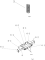
- FIG. 5 is a structurally schematic diagram of one return spring 5. Two ends of each of the return springs 5 are fitted with the first spring holding plate 1-5 (referring to FIG. 1 ) at the bottom of the base 1 and a second spring holding plate 6-4 (referring to FIG. 6 ),respectively.
- FIG. 17 shows the return springs 5 after installation.
- FIG. 6 is a structurally schematic diagram of the driving sliding plate 6.
- the driving sliding plate has two troughs 6-6 in a middle thereof. One end of each of the troughs 6-6 is provided with the second spring holding plate 6-4, and the second spring holding plate 6-4 cooperates with the first spring holding plate 1-5 so that each of the return springs 5 is compressed or extended therebetween.
- the driving sliding plate 6 is engaged with the base 1 in a manner of sliding.
- the driving sliding plate 6 has a slide groove 6-1.
- One slide rail 1-3 of the base 1 is inserted into the slide groove 6-1 and is able to slide left and right.
- the slide rail may be provided on the driving sliding plate 6, and the slide groove may be provided on the base 1.
- the third column 6-5 of the driving sliding plate is fitted rotatably with the driving sliding plate hole 4-1 of the connecting rod 4, and the structure after installation is shown in FIG. 18 .
- two return springs 5, two second spring holding plates 6-4 and two first spring holding plates 1-5 are provided to increase the spring return force.
- the driving sliding plate 6 is driven to move by the reverse force of the internal structure of the machine opposite to the pushing direction, the return springs 5 are compressed, the driving sliding plate 6 drives the connecting rod 4 to move, and the rotating block 3 rotates, so that the toner discharge channel 3-1 communicates with the toner outlet 1-7, thereby realizing toner discharging.
- the present application has beneficial effects of smooth installation, protection of the internal installation structure of the machine, and automatic closing of the toner outlet upon removing the toner container from the machine.
- the structure and shape are simple, the production process requirements are lower, and the failure rate is low.
- the switch device further comprises a fixed cover plate 7.
- FIG. 7 is a structurally schematic diagram of the fixed cover plate 7. Multiples buckles 7-1 of the fixed cover plate 7 are engaged with multiple buckle holes 1-1 of the base 1, respectively. Multiple first columns 1-2 of the base 1 are inserted into multiple first insert holes 7-2 of the fixed cover plate 7, respectively. Six first columns and six first insert holes are shown in figures.
- the second column 1-6 of the base 1 is inserted into a second insert hole 7-4 of the fixed cover plate 7, and a pressing plane 7-5 is provided to level the base 1 and the fixed cover plate 7.
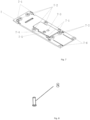
- Two second screw holes 7-6 of the fixed cover plate 7 are coupled with two first screw holes 1-4 of the base 1 through two self-tapping screws 8 shown in FIG. 8 , respectively.
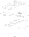
- FIG. 19 is an exploded view of the switch device according to this implementation.
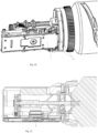
- FIG. 20 is a structural diagram of the switch device according to the present application and the toner container after installation, and FIG. 21 is a cross-sectional view of FIG. 20 .
- FIG. 22 shows an exploded view of the switch device according to the present application and the toner container.
- FIG. 23 shows a structural view of the toner container and the machine without outer casing.
- a driving sliding plate holding portion 9 gradually contacts two second holding portions 6-3 of the driving sliding plate 6.
- the driving sliding block 6 will move in a direction opposite to the direction of loading the toner container into the machine (the reverse direction of arrow F); and by cooperating with the driving sliding block 6, the connecting rod 4 simultaneously moves opposite to the direction of installing the toner container (the reverse direction of arrow F).
- FIG. 9 shows the initial state of the rotating block.
- the rotating block is gradually stressed and gradually rotates to the position shown in FIG. 10 under the traction of the connecting rod 4, and finally rotates to the state shown in FIG. 11 .
- every return spring 5 is compressed to the lowest position by every second spring holding plate 6-4 and every first spring holding plate 1-5.
- the toner outlet of the toner container is gradually opened.
- FIG. 12 shows the initial position of the rotating block 3.
- the toner outlet 1-7 is blocked by the rotating block plate part 3-4 of the rotating block 3 attached with the compressed sealing cotton piece 2.
- the rotating block 3 attached with the compressed sealing cotton piece 2 continues to rotate to the state shown in FIG. 13 , and finally rotates to the state shown in FIG. 14 , thereby realizing that the four holes, i.e., the toner outlet 1-7, the first toner discharge hole 2-1 of the compressed sealing cotton piece 2, the toner discharge channel 3-1 of the rotating block 3, and the second toner discharge hole 7-3 of the fixed cover plate 7, are coaxial with each other, so as to achieve a communication state.
- the toner inside the toner container is able to flow out through the toner port.
- the driving sliding plate holding portion 9 gradually separates from first holding portions 6-2 and second holding portions 6-3 of the driving sliding plate 6 of the machine, and every return spring 5 rebounds from the lowest position, caused by the compression of every second spring holding plate 6-4 and every first spring holding plate 1-5, to drive the driving sliding plate 6 and the connecting rod 4 to move in the direction of the elastic force of every return spring 5.
- the connecting rod 4 drives the rotating block 3 to rotate from the state of FIG. 14 , through the state of FIG. 13 , and finally to the state of FIG. 12 , thereby realizing the closing function of the toner outlet 1-7.
Landscapes
- Physics & Mathematics (AREA)
- General Physics & Mathematics (AREA)
- Dry Development In Electrophotography (AREA)
Abstract
Description
- The present application relates to the technology field of a driving switch for a toner port of a toner feeding container, and more specifically, to a switch device for a toner port of a toner container.
- A toner container is an important accessory for a printer and a copy, especially, whether the opening and closing of a toner port is smooth may affect the print quality. The Patent No.
US 10209667 B2 of Canon Corporation of Japan - In view of the problems in the prior art, the present application proposes a switch device for a toner port of a toner container. The switch device comprises a base for accommodating the toner container, wherein the base has a toner outlet; a rotating block having a toner discharge channel, wherein the rotating block is rotatably coupled to the base; and a driving sliding plate for driving the rotating block to rotate, wherein the toner port of the toner container is opened when the rotating block rotates to a position where the toner discharge channel communicates with the toner outlet, and the toner port of the toner container is closed when the toner discharge channel does not communicate with the toner outlet.
- Preferably, the switch device further comprises a connecting rod, which has a first end coupled to the rotating block for driving the rotating block to rotate and a second end connected to the driving sliding plate.
- Preferably, the switch device further comprises a compressed sealing cotton piece, which is attached on the rotating block, has a first toner discharge hole, and is located between the base and the rotating block after installation, wherein the first toner discharge hole is coaxial with the toner discharge channel of the rotating block.
- Preferably, the driving sliding plate has a slide groove, the base comprises a slide rail, and the slide rail is inserted into the slide groove to achieve sliding fit.
- Preferably, the switch device further comprises a return spring, which is arranged between a second spring holding plate of the driving sliding plate and a first spring holding plate of the base, and is compressed when the driving sliding plate slides.
- Preferably, the switch device further comprises a fixed cover plate, which is engaged with the base and has a second toner discharge hole, wherein a compressed sealing cotton piece, the rotating block, a connecting rod and the driving sliding plate are located between the fixed cover plate and the base, and the second toner discharge hole of the fixed cover plate is coaxial with the toner outlet of the base.
- Preferably, the rotating block comprises a rotating block plate part, and the toner outlet of the base is closed by the rotating block plate part when the rotating block rotates to a position where the toner discharge channel does not communicate with the toner outlet of the base so as to achieve closing the toner port of the toner container.
- Preferably, the driving sliding plate has a first holding portion, at which the driving sliding plate is driven to slide when the toner container is loaded.
- Preferably, the rotating block has a circular shape, a fanned shape, a V-shape or other irregular shapes.
- Preferably, the return spring is compressed when the toner container is loaded, and the return spring is reset when the toner container is removed.
- The beneficial effects of the present application are smooth installation and protection of the internal installation structure of the machine. When the toner container is removed from the machine, the toner port is closed automatically. Compared with the prior art, the structure and shape of the switch device is simplified, the production process requirements are lower, and the failure rate is low.
- In order that the present application may be understood more easily, the present application is described in more detail with reference to specific implementations with the accompanying drawings. These drawings depict only typical implementations of the present application and should not be considered as limiting the scope of the present application.
-
FIG. 1 is a perspective view of a base of a switch device according to the present application. -
FIG. 2 is a perspective view of a compressed sealing cotton piece of the switch device according to the present application. -
FIG. 3 is a perspective view of a rotating block of the switch device according to the present application. -
FIG. 4 is a perspective view of a connecting rod of the switch device according to the present application. -
FIG. 5 is a perspective view of a return spring of the switch device according to the present application. -
FIG. 6 is a perspective view of a driving sliding plate of the switch device according to the present application. -
FIG. 7 is a perspective view of a fixed cover plate of the switch device according to the present application. -
FIG. 8 is a perspective view of a screw of the switch device according to the present application. -
FIG. 9 is a perspective view of an assembled and installed main structure of the switch device according to the present application, in which a toner outlet is not opened. -
FIG. 10 is a perspective view of the assembled and installed main structure of the switch device according to the present application, in which the toner outlet is in a process of being opened. -
FIG. 11 is a perspective view of the assembled and installed main structure, in which the toner outlet is opened. -
FIG. 12 is a cross-sectional view of the assembled main structure ofFIG. 9 , corresponding toFIG. 9 in which the toner outlet is not opened. -
FIG. 13 is a cross-sectional view of the assembled main structure ofFIG. 10 , corresponding toFIG. 10 in which the toner outlet is in the process of being opened. -
FIG. 14 is a cross-sectional view of the assembled main structure ofFIG. 11 , corresponding toFIG. 11 in which the toner outlet is opened. -
FIG. 15 is a perspective view of the rotating block installed on the assembly diagram. -
FIG. 16 is a perspective view of the connecting rod installed on the rotating block. -
FIG. 17 is a perspective view of the return spring installed on the base. -
FIG. 18 is a perspective view of the driving sliding plate installed on the base. -
FIG. 19 is an exploded view of the switch device according to the present application. -
FIG. 20 is a perspective view of the fixed cover plate installed on the base. -
FIG. 21 is a partial cross-sectional view ofFIG. 20 after installation. -
FIG. 22 is an exploded view of the switch device according to the present application with the toner container installed together. -
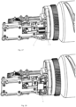
FIG. 23 is a schematic diagram of the toner container and an internal structure of a machine without outer casing. -
FIG. 24 is a schematic diagram of the toner container and the internal structure of the machine from another perspective without outer casing. -
FIGS. 25-27 are perspective views of multiple implementations of the rotating block of the switch device according to the present application. - 1: base; 1-1: buckle hole; 1-2: first column; 1-3: slide rail; 1-4: first screw hole; 1-5: first spring holding plate; 1-6: second column; 1-7: toner outlet; 1-8: spring groove; 2: compressed sealing cotton piece; 2-1: first toner discharge hole; 2-2: axial hole; 3: rotating block; 3-1: toner discharge channel; 3-2: sliding positioning hole; 3-3: connecting rod column; 3-4: rotating block plate part; 4: connecting rod; 4-1: driving sliding plate hole; 4-2: rotating block hole; 5: return spring; 6: driving sliding plate; 6-1: slide groove; 6-2 first holding portion; 6-3: second holding portion; 6-4: second spring holding plate; 6-5: third column; 6-6: trough; 7: fixed cover plate; 7-1: buckle; 7-2: first insert hole; 7-3: second toner discharge hole; 7-4: second insert hole; 7-5: pressing plane; 7-6: second screw hole; 8: self-tapping screw; 9: driving sliding plate holding portion.
- The implementations of the present application are described below with reference to the accompanying drawings, so that those skilled in the art are able to better understand the present application and implement it. However, the enumerated embodiments are not intended to limit the present application. In the absence of conflict, the following embodiments and the technical features in the embodiments are able to be combined with each other, and the same components are denoted by the same reference numbers.
- As shown in
FIG. 1 , a switch device for a toner port of a toner container according to the present application comprises abase 1, a compressed sealingcotton piece 2, and a rotatingblock 3. Thebase 1 has a toner outlet 1-7, and a second column 1-6 is provided next to the toner outlet 1-7. The toner outlet 1-7 defines a first channel of the toner container for outputting toner outwards. Thebase 1 has two spring grooves 1-8 at a bottom thereof for accommodating tworeturn springs 5, respectively. A first spring holding plate 1-5 is against one end of each of thereturn springs 5. Two slide rails 1-3 are set on the bottom of thebase 1 for fitting with two slide grooves 6-1 of a driving sliding plate 6 respectively (referring toFIG. 6 ). -
FIG. 2 is a structurally schematic diagram of the compressed sealingcotton piece 2. The compressedsealing cotton piece 2 has a shape similar to a triangle, while a circumference thereof is smooth arc-shaped. The compressed sealing cotton piece has a first toner discharge hole 2-1 and an axial hole 2-2. The compressedsealing cotton piece 2 is installed under thebase 1, the first toner discharge hole 2-1 is aligned with the toner outlet 1-7, and the second column 1-6 is inserted into the axial hole 2-2. -
FIG. 3 is a structurally schematic diagram of therotating block 3. Therotating block 3 also has a shape similar to a triangle. - Preferably, the compressed
sealing cotton piece 2 is attached to therotating block 3, and therotating block 3 is located below the compressed sealingcotton piece 2 and then installed below thebase 1. Preferably, thebase 1 has a notch for accommodating therotating block 3. The shape of the compressed sealingcotton piece 2 is preferably the same as that of therotating block 3. The first toner discharge hole 2-1 of the compressed sealingcotton piece 2 is coaxial with a toner discharge channel 3-1, which has a certain height, of therotating block 3. - The
rotating block 3 comprises a rotating block plate part 3-4. The toner discharge channel 3-1, a sliding positioning hole 3-2 and a connecting rod column 3-3 are provided on the rotating block plate part 3-4. The first toner discharge hole 2-1 is coaxial with the toner discharge channel 3-1, i.e., after the compressedsealing cotton piece 2 is installed, the toner discharge channel 3-1, the first toner discharge hole 2-1 and the toner outlet 1-7 are coaxial (referring toFIG. 12 ). The second column 1-6 passes through the axial hole 2-2 and the sliding positioning hole 3-2 to connect therotating block 3 with thebase 1, and the sliding positioning hole 3-2 is in sliding fit with the second column 1-6. The connecting rod column 3-3 passes through a rotating block hole 4-2 of a connecting rod 4 (referring toFIG. 4 andFIG. 16 ). The axial hole 2-2 is coaxial with the sliding positioning hole 3-2. - The
rotating block 3 may also be other shapes, such as circular, fan-shaped and V-shaped, as shown inFIGS. 25-27 , as long as therotating block 3 is able to rotate, discharge toner and block toner. It should be noted that, as shown inFIG. 26 , the rotating block plate part 3-4 is V-shaped, wherein the toner discharge channel 3-1 is provided on one branch of the rotating block plate part 3-4, and no hole is provided in the other branch so that the toner outlet 1-7 is blocked. -
FIG. 4 is a structurally schematic diagram of the connectingrod 4. The connectingrod 4 has the rotating block hole 4-2 and a driving sliding plate hole 4-1 at two ends thereof, respectively. As mentioned above, the rotating block hole 4-2 is fitted rotatably with the connecting rod column 3-3 (referring toFIG. 16 ), and the driving sliding plate hole 4-1 is fitted rotatably with a third column 6-5 of the driving sliding plate 6 (referring toFIG. 6 andFIG. 18 ). In this way, when the driving sliding plate 6 slides left and right, the connectingrod 4 is driven to slide left and right for driving therotating block 3 to swing forward and backward, so that the toner outlet 1-7 is switched between an open state and a closed state. -
FIG. 5 is a structurally schematic diagram of onereturn spring 5. Two ends of each of the return springs 5 are fitted with the first spring holding plate 1-5 (referring toFIG. 1 ) at the bottom of thebase 1 and a second spring holding plate 6-4 (referring toFIG. 6 ),respectively.FIG. 17 shows the return springs 5 after installation. -
FIG. 6 is a structurally schematic diagram of the driving sliding plate 6. The driving sliding plate has two troughs 6-6 in a middle thereof. One end of each of the troughs 6-6 is provided with the second spring holding plate 6-4, and the second spring holding plate 6-4 cooperates with the first spring holding plate 1-5 so that each of the return springs 5 is compressed or extended therebetween. As shown inFIGS. 16-18 , after the installation is completed, the driving sliding plate 6 is engaged with thebase 1 in a manner of sliding. In one embodiment, the driving sliding plate 6 has a slide groove 6-1. One slide rail 1-3 of thebase 1 is inserted into the slide groove 6-1 and is able to slide left and right. Alternatively, the slide rail may be provided on the driving sliding plate 6, and the slide groove may be provided on thebase 1. The third column 6-5 of the driving sliding plate is fitted rotatably with the driving sliding plate hole 4-1 of the connectingrod 4, and the structure after installation is shown inFIG. 18 . Preferably, tworeturn springs 5, two second spring holding plates 6-4 and two first spring holding plates 1-5 are provided to increase the spring return force. - In this way, during the pushing process of the toner container, the driving sliding plate 6 is driven to move by the reverse force of the internal structure of the machine opposite to the pushing direction, the return springs 5 are compressed, the driving sliding plate 6 drives the connecting
rod 4 to move, and therotating block 3 rotates, so that the toner discharge channel 3-1 communicates with the toner outlet 1-7, thereby realizing toner discharging. - On the contrary, when the toner container is taken out from the machine, under an action of elastic force of the return springs 5, the driving sliding plate 6 is driven to pull the connecting
rod 4 for rotating therotating block 3, so that the toner discharge channel 3-1 does not communicate with the toner outlet 1-7, thereby closing the toner outlet of the toner container. - The present application has beneficial effects of smooth installation, protection of the internal installation structure of the machine, and automatic closing of the toner outlet upon removing the toner container from the machine. At the same time, the structure and shape are simple, the production process requirements are lower, and the failure rate is low.
- Preferably, the switch device according to the present application further comprises a fixed
cover plate 7.FIG. 7 is a structurally schematic diagram of the fixedcover plate 7. Multiples buckles 7-1 of the fixedcover plate 7 are engaged with multiple buckle holes 1-1 of thebase 1, respectively. Multiple first columns 1-2 of thebase 1 are inserted into multiple first insert holes 7-2 of the fixedcover plate 7, respectively. Six first columns and six first insert holes are shown in figures. The second column 1-6 of thebase 1 is inserted into a second insert hole 7-4 of the fixedcover plate 7, and a pressing plane 7-5 is provided to level thebase 1 and the fixedcover plate 7. Two second screw holes 7-6 of the fixedcover plate 7 are coupled with two first screw holes 1-4 of thebase 1 through two self-tapping screws 8 shown inFIG. 8 , respectively. Thebase 1 and the fixedcover plate 7 are coupled together, so that therotating block 3 attached with the compressedsealing cotton piece 2 is able to be pressed on thebase 1. In addition, the fixedcover plate 7 has a second toner discharge hole 7-3, which is coaxial with the toner outlet 1-7.FIG. 19 is an exploded view of the switch device according to this implementation.FIG. 20 is a structural diagram of the switch device according to the present application and the toner container after installation, andFIG. 21 is a cross-sectional view ofFIG. 20 . -
FIG. 22 shows an exploded view of the switch device according to the present application and the toner container.FIG. 23 shows a structural view of the toner container and the machine without outer casing. During the installation process of the toner container in the machine, a driving sliding plate holding portion 9 gradually contacts two second holding portions 6-3 of the driving sliding plate 6. Through the reaction force, as the toner container continues to be pushed in, the driving sliding block 6 will move in a direction opposite to the direction of loading the toner container into the machine (the reverse direction of arrow F); and by cooperating with the driving sliding block 6, the connectingrod 4 simultaneously moves opposite to the direction of installing the toner container (the reverse direction of arrow F). Since the connectingrod 4 is slidingly fitted with therotating block 3, and therotating block 3 is rotatably fitted on the second column 1-6, therotating block 3 is able to rotate. When the connectingrod 4 moves, therotating block 3 begins to rotate under force.FIG. 9 shows the initial state of the rotating block. As the toner container is continuously loaded into the machine, the rotating block is gradually stressed and gradually rotates to the position shown inFIG. 10 under the traction of the connectingrod 4, and finally rotates to the state shown inFIG. 11 . During this process, everyreturn spring 5 is compressed to the lowest position by every second spring holding plate 6-4 and every first spring holding plate 1-5. During the above rotation process, the toner outlet of the toner container is gradually opened. -
FIG. 12 shows the initial position of therotating block 3. The toner outlet 1-7 is blocked by the rotating block plate part 3-4 of therotating block 3 attached with the compressedsealing cotton piece 2. As the toner container is gradually installed into the machine, therotating block 3 attached with the compressedsealing cotton piece 2 continues to rotate to the state shown inFIG. 13 , and finally rotates to the state shown inFIG. 14 , thereby realizing that the four holes, i.e., the toner outlet 1-7, the first toner discharge hole 2-1 of the compressed sealingcotton piece 2, the toner discharge channel 3-1 of therotating block 3, and the second toner discharge hole 7-3 of the fixedcover plate 7, are coaxial with each other, so as to achieve a communication state. In this way, the toner inside the toner container is able to flow out through the toner port. - When the toner container is taken out from the machine, as shown in
FIG. 24 , the driving sliding plate holding portion 9 gradually separates from first holding portions 6-2 and second holding portions 6-3 of the driving sliding plate 6 of the machine, and everyreturn spring 5 rebounds from the lowest position, caused by the compression of every second spring holding plate 6-4 and every first spring holding plate 1-5, to drive the driving sliding plate 6 and the connectingrod 4 to move in the direction of the elastic force of everyreturn spring 5. The connectingrod 4 drives therotating block 3 to rotate from the state ofFIG. 14 , through the state ofFIG. 13 , and finally to the state ofFIG. 12 , thereby realizing the closing function of the toner outlet 1-7. - The above-described embodiments are only preferred specific implementations of the present application. The phrases "in one embodiment", "in another embodiment", "in yet another embodiment" or "in other embodiments" mentioned in this specification may refer to one or more of the same or different embodiments according to the present disclosure. The usual changes and substitutions made by those skilled in the art within the scope of the technical solutions of the present application should be included in the protection scope of the present application.
Claims (10)
- A switch device for a toner port of a toner container, comprising:a base (1) for accommodating the toner container, wherein the base (1) has a toner outlet (1-7);a rotating block (3) having a toner discharge channel (3-1), wherein the rotating block (3) is rotatably coupled to the base (1); anda driving sliding plate (6) for driving the rotating block (3) to rotate,wherein the toner port of the toner container is opened when the rotating block (3) rotates to a position where the toner discharge channel (3-1) communicates with the toner outlet (1-7), and the toner port of the toner container is closed when the toner discharge channel (3-1) does not communicate with the toner outlet (1-7).
- The switch device according to claim 1, further comprising:
a connecting rod (4), which has a first end coupled to the rotating block (3) for driving the rotating block (3) to rotate and a second end connected to the driving sliding plate (6). - The switch device according to claim 1, further comprising:
a compressed sealing cotton piece (2), which is attached on the rotating block (3), has a first toner discharge hole (2-1), and is located between the base (1) and the rotating block (3) after installation, wherein the first toner discharge hole (2-1) is coaxial with the toner discharge channel (3-1) of the rotating block (3). - The switch device according to claim 1, wherein the driving sliding plate (6) has a slide groove (6-1), the base (1) comprises a slide rail (1-3), and the slide rail (1-3) is inserted into the slide groove (6-1) to achieve sliding fit.
- The switch device according to claim 1, further comprising:
a return spring (5), which is arranged between a second spring holding plate (6-4) of the driving sliding plate (6) and a first spring holding plate (1-5) of the base (1), and is compressed when the driving sliding plate (6) slides. - The switch device according to claim 4, further comprising:
a fixed cover plate (7), which is engaged with the base (1) and has a second toner discharge hole (7-3), wherein a compressed sealing cotton piece (2), the rotating block (3), a connecting rod (4) and the driving sliding plate (6) are located between the fixed cover plate (7) and the base (1), and the second toner discharge hole (7-3) of the fixed cover plate (7) is coaxial with the toner outlet (1-7) of the base (1). - The switch device according to claim 1, wherein the rotating block (3) comprises a rotating block plate part (3-4), and the toner outlet (1-7) of the base (1) is closed by the rotating block plate part (3-4) when the rotating block rotates to a position where the toner discharge channel (3-1) does not communicate with the toner outlet (1-7) of the base (1), so as to achieve closing the toner port of the toner container.
- The switch device according to claim 1, wherein the driving sliding plate (6) comprises a first holding portion (6-2), at which the driving sliding plate (6) is driven to slide when the toner container is loaded.
- The switch device according to claim 1, wherein the rotating block (3) has a circular shape, a fanned shape, a V-shape or other irregular shapes.
- The switch device according to claim 5, wherein the return spring (5) is compressed when the toner container is loaded, and the return spring (5) is reset when the toner container is removed.
Applications Claiming Priority (2)
| Application Number | Priority Date | Filing Date | Title |
|---|---|---|---|
| CN202110802003.7A CN115616878B (en) | 2021-07-15 | 2021-07-15 | A switching device for the toner outlet of a toner supply |
| PCT/CN2021/119500 WO2023284109A1 (en) | 2021-07-15 | 2021-09-22 | Switch device of toner outlet of toner feeder |
Publications (2)
| Publication Number | Publication Date |
|---|---|
| EP4372477A1 true EP4372477A1 (en) | 2024-05-22 |
| EP4372477A4 EP4372477A4 (en) | 2025-07-09 |
Family
ID=84855413
Family Applications (1)
| Application Number | Title | Priority Date | Filing Date |
|---|---|---|---|
| EP21949884.7A Pending EP4372477A4 (en) | 2021-07-15 | 2021-09-22 | Switch device of toner outlet of toner feeder |
Country Status (4)
| Country | Link |
|---|---|
| US (1) | US20250321515A1 (en) |
| EP (1) | EP4372477A4 (en) |
| CN (1) | CN115616878B (en) |
| WO (1) | WO2023284109A1 (en) |
Family Cites Families (15)
| Publication number | Priority date | Publication date | Assignee | Title |
|---|---|---|---|---|
| JPH07168435A (en) * | 1993-10-04 | 1995-07-04 | Seiko Epson Corp | Toner supply device |
| JP3531294B2 (en) * | 1994-10-19 | 2004-05-24 | 三菱電機株式会社 | Cartridge changer |
| JP2000315041A (en) * | 1999-04-30 | 2000-11-14 | Sharp Corp | Powder transport mechanism |
| JP4054521B2 (en) * | 1999-11-29 | 2008-02-27 | キヤノン株式会社 | Developer supply cartridge and developer supply system |
| EP2048546A3 (en) * | 2000-09-01 | 2011-03-16 | Canon Kabushiki Kaisha | Cartridge having developer supply opening and image forming apparatus usable therewith |
| KR100582998B1 (en) * | 2004-05-04 | 2006-05-25 | 삼성전자주식회사 | Process Cartridge of Image Forming Device |
| CN101395542B (en) * | 2006-03-10 | 2012-01-04 | 佳能株式会社 | Process cartridge, developer supply cartridge, and electrophotographic image forming apparatus |
| JP6083954B2 (en) | 2011-06-06 | 2017-02-22 | キヤノン株式会社 | Developer supply container and developer supply system |
| CN106681115A (en) * | 2015-11-05 | 2017-05-17 | 珠海艾派克科技股份有限公司 | Toner cartridge and an image forming device |
| US9869949B2 (en) * | 2014-01-20 | 2018-01-16 | Ninestar Corporation | Toner cartridge with a toner switch assembly |
| CN205193435U (en) * | 2015-11-05 | 2016-04-27 | 珠海艾派克科技股份有限公司 | Cartridge and image forming device |
| CN108508724B (en) * | 2018-04-03 | 2024-09-13 | 珠海天威飞马打印耗材有限公司 | Toner container and method for opening and closing a toner outlet on the toner container |
| CN110083034A (en) * | 2019-06-04 | 2019-08-02 | 珠海天威飞马打印耗材有限公司 | A kind of cartridge |
| CN209928215U (en) * | 2019-07-19 | 2020-01-10 | 纳思达股份有限公司 | Powder cylinder |
| CN215729289U (en) * | 2021-07-15 | 2022-02-01 | 北京新晨办公设备有限公司 | Switching device for powder outlet of powdered ink container |
-
2021
- 2021-07-15 CN CN202110802003.7A patent/CN115616878B/en active Active
- 2021-09-22 US US18/579,431 patent/US20250321515A1/en active Pending
- 2021-09-22 EP EP21949884.7A patent/EP4372477A4/en active Pending
- 2021-09-22 WO PCT/CN2021/119500 patent/WO2023284109A1/en not_active Ceased
Also Published As
| Publication number | Publication date |
|---|---|
| CN115616878A (en) | 2023-01-17 |
| CN115616878B (en) | 2026-03-24 |
| WO2023284109A1 (en) | 2023-01-19 |
| US20250321515A1 (en) | 2025-10-16 |
| EP4372477A4 (en) | 2025-07-09 |
Similar Documents
| Publication | Publication Date | Title |
|---|---|---|
| US9032590B2 (en) | Rotating mechanism and electronic device with same | |
| US6737577B1 (en) | Housing opening structure | |
| CN113491242A (en) | Feeding device and discharging adjustment structure thereof | |
| CN100437795C (en) | Disk drive device | |
| EP3850944B1 (en) | Snack machine for pets | |
| CN107321041B (en) | Water purifier with conveniently replaced filter element | |
| US20250321515A1 (en) | Switch device for toner port of toner container | |
| US10394163B2 (en) | Toner cartridge with a toner switch assembly | |
| CN111017386A (en) | A flake storage mechanism | |
| CN215729289U (en) | Switching device for powder outlet of powdered ink container | |
| CN114335869A (en) | Self-locking pop-up type battery box mechanism | |
| KR101275315B1 (en) | Optical disc drive device and driving method thereof | |
| CN116025244B (en) | Door opening and closing structure and discharging device | |
| KR950005099B1 (en) | Disc cartridge loading device for mini disc player | |
| US7359187B2 (en) | Apparatus for mounting removably a disk drive in an electronic device | |
| CN114635265A (en) | Transmission mechanism of washing machine and washing machine | |
| CN115347478A (en) | Be applied to high-efficient power mounting structure of switch board | |
| CN219862962U (en) | Cable well convenient to open | |
| CN218363399U (en) | Clamping and positioning device | |
| CN219959282U (en) | Wireless control device | |
| WO2015101086A1 (en) | Processing cartridge and image formation apparatus | |
| CN109892681A (en) | A kind of sauce distributor | |
| CN222898817U (en) | A horizontal screw juicer | |
| CN215932531U (en) | Case convenient for disassembling and assembling hard disk | |
| CN223845187U (en) | Water cup with detachable braces for storage |
Legal Events
| Date | Code | Title | Description |
|---|---|---|---|
| STAA | Information on the status of an ep patent application or granted ep patent |
Free format text: STATUS: THE INTERNATIONAL PUBLICATION HAS BEEN MADE |
|
| PUAI | Public reference made under article 153(3) epc to a published international application that has entered the european phase |
Free format text: ORIGINAL CODE: 0009012 |
|
| STAA | Information on the status of an ep patent application or granted ep patent |
Free format text: STATUS: REQUEST FOR EXAMINATION WAS MADE |
|
| 17P | Request for examination filed |
Effective date: 20240202 |
|
| AK | Designated contracting states |
Kind code of ref document: A1 Designated state(s): AL AT BE BG CH CY CZ DE DK EE ES FI FR GB GR HR HU IE IS IT LI LT LU LV MC MK MT NL NO PL PT RO RS SE SI SK SM TR |
|
| DAV | Request for validation of the european patent (deleted) | ||
| DAX | Request for extension of the european patent (deleted) | ||
| A4 | Supplementary search report drawn up and despatched |
Effective date: 20250605 |
|
| RIC1 | Information provided on ipc code assigned before grant |
Ipc: G03G 15/08 20060101AFI20250530BHEP |