EP4372425A1 - Faseroptisches dosimeter für räumliche umgebung und dosimetrieverfahren - Google Patents
Faseroptisches dosimeter für räumliche umgebung und dosimetrieverfahren Download PDFInfo
- Publication number
- EP4372425A1 EP4372425A1 EP23210442.2A EP23210442A EP4372425A1 EP 4372425 A1 EP4372425 A1 EP 4372425A1 EP 23210442 A EP23210442 A EP 23210442A EP 4372425 A1 EP4372425 A1 EP 4372425A1
- Authority
- EP
- European Patent Office
- Prior art keywords
- light beam
- optical fiber
- radiosensitive
- optical
- dosimeter
- Prior art date
- Legal status (The legal status is an assumption and is not a legal conclusion. Google has not performed a legal analysis and makes no representation as to the accuracy of the status listed.)
- Granted
Links
Images
Classifications
-
- G—PHYSICS
- G01—MEASURING; TESTING
- G01T—MEASUREMENT OF NUCLEAR OR X-RADIATION
- G01T1/00—Measuring X-radiation, gamma radiation, corpuscular radiation, or cosmic radiation
- G01T1/02—Dosimeters
- G01T1/026—Semiconductor dose-rate meters
-
- G—PHYSICS
- G01—MEASURING; TESTING
- G01T—MEASUREMENT OF NUCLEAR OR X-RADIATION
- G01T1/00—Measuring X-radiation, gamma radiation, corpuscular radiation, or cosmic radiation
- G01T1/02—Dosimeters
-
- G—PHYSICS
- G01—MEASURING; TESTING
- G01T—MEASUREMENT OF NUCLEAR OR X-RADIATION
- G01T1/00—Measuring X-radiation, gamma radiation, corpuscular radiation, or cosmic radiation
- G01T1/02—Dosimeters
- G01T1/06—Glass dosimeters using colour change; including plastic dosimeters
-
- G—PHYSICS
- G01—MEASURING; TESTING
- G01T—MEASUREMENT OF NUCLEAR OR X-RADIATION
- G01T7/00—Details of radiation-measuring instruments
- G01T7/005—Details of radiation-measuring instruments calibration techniques
Definitions
- the present invention relates to a point dosimeter for providing high precision irradiation dose measurement in real time.
- the invention also relates to a dosimeter for providing a measurement of total ionizing dose (TID) over a wide dynamic range and/or over a long duration.
- TID total ionizing dose
- such a dosimetry apparatus, device and method finds applications in the space domain, in any type of space radiative environment, or even in the medical, scientific domain in high energy physics, as a reference sensor for other dosimeters, or in the nuclear field.
- Dosimetry it is important to be able to carry out dosimetry in any type of space radiation environment, that is to say on any type of platform and on all orbits. Indeed, manned flights, missions to the surface of the moon or planets, space probes, samples taken during space missions or even flights in stratospheric balloons are exposed to different radiative environments, called space radiative environments. For example, it is important to be able to measure the radiation dose received by an astronaut in a space station at each moment and cumulatively over the entire duration of a mission. Dosimetry, resolved in time, can also allow the detection of solar flares or the control of neutrons received during an extravehicular, lunar or planetary mission.
- Passive dosimeters based on thermo-luminescent materials are known, which can be stimulated optically or by measurements of defect concentration by electronic paramagnetic resonance. These passive dosimeters are read after irradiation but do not allow precise dose measurement in real time.
- active dosimeters for example based on microelectronic components.
- an optical fiber dosimeter based on a measurement of attenuation induced by irradiation (or RIA for “Radiation Induced Attenuation” in English) also called measurement of losses induced by irradiation for different types of radiation: ions, protons, electrons, neutrons and/or photons.
- a dosimeter comprising a radiosensitive optical fiber, a light source and a photodetector to measure, as a function of time, the optical power losses of the light beam transmitted through the optical fiber to deduce therefrom, thanks to to a pre-calibration, the attenuation induced by irradiation in the optical fiber.
- An optical fiber is made radiosensitive by doping the core and/or the optical cladding, for example with phosphorus, which makes the optical fiber sensitive to ionizing radiation.
- Certain dosimeters based on the measurement of RIA in an optical fiber make it possible to achieve high sensitivity at low irradiation doses, for example with a sensitivity of the order of 1 dB.km -1 .Gy -1 and a precision of 20%.
- the RIA generally depends on temperature and dose rate and decreases significantly after the end of irradiation exposure.
- the intensity of the light source limits the measurement dynamics.
- a dosimeter may include a part exposed to irradiation and another part protected from irradiation.
- the entire system is subject to irradiation.
- the space environment imposes drastic operating conditions: small footprint, low mass and low energy consumption, mechanical resistance to shocks and vibrations and insensitivity to strong thermal variations in the space environment. These conditions make it very difficult to use fiber optic dosimeters in a space environment for precise dose measurements.
- One of the aims of the invention is to provide an active dosimeter with high precision over a wide dynamic range, in particular at very low doses and radiation dose rates.
- Another aim of the invention is to propose a point dosimeter having a response independent of temperature and dose rate, in particular for applications in a space environment.
- Yet another aim of the invention is to provide a dosimeter sensitive to the irradiation of electrons, protons, photons, neutrons and/or ions.
- the invention relates to a dosimeter comprising a light source capable of generating a light beam, an optical coupler-splitter capable of receiving the light beam emitted by the light source and of separately transmitting a first part of the light beam and a second part of the light beam, a radiosensitive optical fiber, the radiosensitive optical fiber being arranged to receive the first part of the light beam, a first photodetector arranged to record a power measurement of the light beam transmitted through the radiosensitive optical fiber, an optical reference arm of optical length less than that of the radiosensitive optical fiber, the optical reference arm being arranged to receive the second part of the light beam, a second photodetector arranged to record a reference power measurement of the light beam transmitted through the optical reference arm, and an electronic system capable of simultaneously receiving the power measurement of the first photodetector and the reference power measurement of the second photodetector, the system electronic being configured to extract a differential measurement of attenuation induced by irradiation in the radiosensitive optical fiber relative to
- the light beam is non-polarized or depolarized, or, respectively, the light beam is polarized and the radiosensitive optical fiber is a polarization-maintaining fiber.
- the light source comprises an amplified spontaneous emission source generating the light beam by amplified stimulated emission, the light beam being non-polarized.
- the dosimeter comprises an active or passive optical device placed downstream of the light source and configured so as to depolarize the light beam.
- the passive optical device comprises a depolarizer, for example a Lyot depolarizer or a polarization combiner, and two polarization-maintaining optical fibers of different lengths.
- a depolarizer for example a Lyot depolarizer or a polarization combiner
- the active optical device comprises an optical phase modulator, for example an electro-optical modulator.
- the light source comprises a laser diode or a superluminescent diode.
- the radiosensitive optical fiber is a single-mode or multi-mode fiber.
- the optical reference arm comprises an optical fiber section.
- the electronic system comprises a logarithmic amplifier configured to simultaneously receive the power measurement of the first photodetector and the reference power measurement of the second photodetector, the logarithmic amplifier being capable of extracting the differential measurement of induced attenuation by irradiation in the radiosensitive optical fiber.
- the light source is capable of emitting the light beam at a first wavelength and at a second wavelength distinct from the first wavelength
- the first photodetector being adapted to record a measurement power of the light beam transmitted through the radiosensitive optical fiber at the first wavelength and the second wavelength
- the second photodetector being adapted to record the reference power measurement at the first wavelength and the second wavelength
- the electronic system is capable of extracting the differential measurement of attenuation induced by irradiation at the first wavelength and at the second wavelength.
- the dosimeter comprises at least one temperature sensor arranged to acquire at least one temperature measurement at at least one point of the dosimeter, and the electronic system is adapted to correct the differential measurement of attenuation induced by irradiation as a function of said at least one temperature measurement.
- the dosimeter comprises a reflective element disposed at a distal end of the radiosensitive optical fiber, the first photodetector being arranged to record the power measurement of the light beam transmitted after a round trip through the radiosensitive optical fiber.
- the first photodetector and the second photodetector each comprise a photodiode.
- the dosimeter comprises another radiosensitive optical fiber and a beam splitter arranged between the light source, the radiosensitive optical fiber and the other radiosensitive optical fiber, the beam splitter being able to divide the beam light between the radiosensitive optical fiber and the other radiosensitive optical fiber, another photodetector arranged to record another measurement of power of the light beam transmitted through the other radiosensitive optical fiber, the electronic system being adapted to receive the other measurement of power of the other photodetector, the electronic system being configured to extract another differential measurement of attenuation induced by irradiation in the other radiosensitive optical fiber relative to the reference optical arm.
- the invention also relates to a dosimetry method comprising the following steps: emission of a light beam; separation of the light beam into a first part of the light beam and a second part of the light beam; injection of the first part of the light beam into a radiosensitive optical fiber, the light beam being depolarized, or, respectively, the light beam being polarized and the radiosensitive optical fiber being a polarization maintaining fiber; injection of the second part of the light beam into a reference optical arm of optical length less than that of the radiosensitive optical fiber, recording on a first photodetector of a power measurement of the light beam transmitted through the radiosensitive optical fiber; recording on a second photodetector a reference power measurement of the light beam transmitted through the optical reference arm; and electronic processing of measuring the power of the first photodetector and the reference power measurement of the second photodetector to extract a differential measurement of attenuation induced by irradiation in the radiosensitive optical fiber relative to the reference optical arm.
- the present disclosure proposes a point dosimeter based on a measurement of attenuation induced by irradiation in a radiosensitive optical fiber.
- the dosimeter is configured to have high sensitivity to low irradiation doses, high precision and high measurement dynamics.
- the dosimeter is stable with respect to variations in ambient temperature.
- a point dosimeter a dosimeter capable of carrying out induced attenuation measurements which are integrated over the entire length of the optical fiber.
- Such a point dosimeter is distinguished from an optical fiber reflectometer, which makes it possible to measure attenuation locally in the fiber and to determine the position of this attenuation as a function of the longitudinal direction of the fiber.
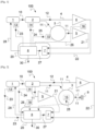
- the dosimeter 100 comprises a light source 1, an optical coupler-splitter 2, a radiosensitive optical fiber 3, a reference arm 4, a first photodetector 5, a second photodetector 6 and a electronic system 20.
- the principle of measurement is based on a differential measurement of optical losses by RIA between two measuring arms of different optical lengths comprising on the one hand the radiosensitive optical fiber 3 and on the other hand the reference arm 4.
- the radiosensitive optical fiber 3 is a fiber whose optical transmission properties vary with the irradiation dose received.
- radiosensitive optical fiber 3 is an optical fiber with a core doped with phosphorus or aluminum.
- the radiosensitive optical fiber 3 is a phosphosilicate or aluminosilicate fiber.
- Such a fiber is sensitive to ionizing radiation in a neutron, X-ray or gamma ray energy range.
- the radiosensitive optical fiber 3 has a great length, between 50 m and 10 km, for example 100 m, 2 km, 5 km or 7 km.
- the length of the optical fiber is optimized taking into account the sensitivity coefficient of this optical fiber to the wavelength(s) of the source used, expressed for example in dB.km -1 .Gy - 1 .
- the radiosensitive optical fiber 3 selected is a 5 km long phosphosilicate fiber.
- the radiosensitive optical fiber 3 is wound in the form of a coil to reduce its bulk.
- the diameter of the coil of radiosensitive optical fiber 3 is generally between 20 mm and 200 mm, for example of the order of 40 mm.
- the radiosensitive optical fiber can be, depending on the embodiments, a single-mode fiber (SM), a multi-mode fiber (MM) or even a polarization maintaining fiber (PM).
- SM single-mode fiber
- MM multi-mode fiber
- PM polarization maintaining fiber
- a reflector 9 is arranged at the distal end of the radiosensitive optical fiber 3.
- the reflector 9 comprises for example a mirror arranged facing the distal end of the radiosensitive optical fiber 3.
- the reflector 9 can also be made up of a reflective treatment applied to the distal end of the radiosensitive optical fiber 3.
- the reflector 9 can also consist of a fiber Bragg reflector.
- the reference arm 4 is an arm which has a much shorter optical path than the radiosensitive optical fiber 3.
- the reference arm 4 comprises for example a section of optical fiber of short length.
- the optical fiber section of the reference arm 4 is of the same structure and/or composition as the radiosensitive optical fiber 3 and of length much shorter than that of the radiosensitive optical fiber 3.
- the optical fiber in the arm reference is not necessarily a radiosensitive fiber.
- the reference arm 4 comprises a section of optical fiber having a length of 1 m.
- the first photodetector 5 and the second photodetector 6 comprise, for example, photodiodes.
- the electronic system 20 makes it possible to monitor and command the active elements, such as the light source 1 and the photodetectors 5, 6.
- the electronic system 20 also makes it possible to process the measurements of the powers transmitted in the radiosensitive optical fiber and in the arm of reference, to calculate the losses induced by irradiation and the corresponding irradiation dose.
- the electronic system 20 also allows the transfer to the user of data 30 including in particular the dose measurement result D extracted from the differential measurement of RIA 27.
- the dosimeter performs real-time measurements, for example acquisition of a measurement point on the two photodetectors 5, 6 every microsecond (in other words at an acquisition rate of MHz), depending on the performance of the detection electronics. This system makes it possible to detect very brief radiative events. This system also makes it possible to perform and read differential RIA measurements in real time.
- the dosimeter 100 includes one or more temperature sensor(s).
- the [ Fig.1 ] illustrates a temperature sensor 13 placed near the light source 1, another temperature sensor 14 placed near the optical coupler-separator 2 and/or yet another temperature sensor 15 placed near the fiber spool radiosensitive optics 3 and/or another temperature sensor 16 placed near the first photodetector 5 and/or the second photodetector 6.
- the photodiodes 5, 6 are placed close to each other in order to that they have the same temperature and that their thermal dependence partially compensates for each other.
- the most useful sensor is the temperature sensor 16 located near the photodetectors 5, 6.
- a calculator 8 uses a model for converting optical losses into dose which uses these point temperature measurements to correct certain drifts due to thermal effects on the components of the dosimeter, in particular on the photodiodes 5, 6 and/or respectively on the fiber. radiosensitive optics 3.
- the light source 1 emits a light beam 10.
- the light beam 10 is in the visible or infrared range.
- the optical coupler-splitter 2 receives the light beam 10 and separates it into a first part of the light beam 11 and a second part of the light beam 12.
- the first part of the light beam 11 is injected at a proximal end of the radiosensitive optical fiber 3
- the second part of the light beam 12 is injected into the reference arm 4.
- the optical coupler-separator 2 is for example a 90:10 coupler so as to inject 90% of the optical power into the radiosensitive optical fiber 3 and. 10% of the optical power remaining in the reference arm 4.
- a 50/50 coupler is used which has a stable optical coupling ratio by symmetry. Other optical coupling ratios are possible without departing from the scope of this disclosure.
- the first photodetector 5 receives the first part of the light beam 11 leaving the radiosensitive optical fiber 3 and the second photodetector 6 receives the second part of the light beam 12 leaving the reference arm 4.
- the first detector 5 thus measures the power 21 of the first part of the light beam 11 after transmission through the radiosensitive optical fiber 3.
- the second photodetector 6 measures the power 22 of the second part of the light beam 12 after transmission through the reference arm 4.
- the reflector 9 reflects the first part of the light beam 11 transmitted a first time through the radiosensitive optical fiber 3 so that it propagates a second time, in the opposite direction, through the radiosensitive optical fiber 3.
- the first detector 5 measures the power 21 of the first part of the light beam 11 after a round trip through the radiosensitive optical fiber 3.
- D the radiation dose received by the radiosensitive optical fiber 3.
- This general formula must be adapted for example in the case of a dosimeter using a mirror as illustrated in [ Fig.2 ], where the length of the optical path is equal to twice the length of the optical fiber.
- a precalibration allows the model to be adjusted across the entire measurement dynamic. It is advantageous to use a significant length L of fiber, for a given precision on the absorption reading A. However, the greater the length L of the radiosensitive optical fiber 3, the greater the absorption A due to radiation in the sensitive fiber is important.
- the initial absorption (before radiation) of the fiber is already of the order of 20 dB.
- the passive coupler-separator 2 which divides the optical power between the second part of the light beam 12 towards the reference arm and the first part of the light beam 11 on the arm which passes through the radiosensitive optical fiber 3 whose attenuation A is to be measured.
- This architecture makes it possible to overcome the power fluctuations of the optical source.
- the difference in optical power measured by the two photodetectors 5 and 6 can be very significant, in particular when the length L of the radiosensitive optical fiber 3 is large, generally several km long, for example 5 km.
- the electronic system 20 is designed to make a ratio between the power 21 of the first part of the light beam 11 and the power 22 of the second part of the light beam 12 so as to obtain a differential attenuation measurement induced by irradiation 27.
- the calculator 8 uses the differential measurement of RIA 27 to deduce the dose D of irradiation received, on the basis of a model for example as described above.
- the fact of normalizing at each instant the power 21 transmitted via the radiosensitive optical fiber 3 in relation to the power 22 transmitted via the reference arm 4 makes it possible to overcome variations in the power of the light source 1 as a function of time.
- the electronic system 20 comprises a logarithmic amplifier 7.
- the logarithmic amplifier 7 is for example an integrated direct current analog logarithmic amplifier (or “integrated DC logarithmic amplifier” in English).
- the logarithmic amplifier 7 receives simultaneously on two distinct input channels the power 21 of the first part of the light beam 11 and the power 22 of the second part of the light beam 12.
- the amplifier logarithmic 7 receives on an input channel the photocurrent emitted by the signal photodiode 5 and on another input channel the photocurrent emitted by the reference photodiode 6.
- the logarithmic amplifier 7 thus makes it possible to compare these photocurrents.
- the logarithmic amplifier 7 directly performs an analog logarithmic ratio operation which makes it possible to directly provide the differential measurement of RIA 27 in decibels.
- the logarithmic amplifier 7 uses the exponential relationship between the voltage and the current in a PN junction to have a relationship between an input current and an output voltage that is intrinsically logarithmic, which makes it possible to obtain a measurement of Accurate attenuation even when the photocurrent varies by several orders of magnitude.
- an electronic system based on the use of two independent transimpedance amplifiers generates a strong difference between the two photocurrents, and requires adjustment of the transimpedance amplifiers in a very unbalanced manner to compensate for this strong difference.
- each analog signal is first digitized via an analog-to-digital converter before applying a digital division calculation
- operations are performed directly and primarily on analog signals.
- the measurement accuracy is not limited by the resolution or the dynamics of an analog-to-digital converter.
- the data flow at the output of the logarithmic amplifier 7 is not limited by the size of the memory blocks. The use of such a logarithmic amplifier 7 makes it possible to greatly increase the precision and dynamics of measurement of the RIA signal by several orders of magnitude, particularly towards low irradiation doses.
- power measurement instabilities linked to polarization effects limit the detection of low doses of radiation.
- the polarization of light is not conserved during propagation in a single-mode (SM) fiber which is not polarization maintained.
- the polarization of a light beam in particular changes very strongly depending on the mechanical stress of the fiber or the temperature. If a polarized light beam is injected into a single-mode fiber, the polarization of the light beam leaving the fiber is difficult to control and changes quickly, particularly due to temperature fluctuations.
- certain optical components essential for the attenuation measurement such as the coupler-separator 2 and the photodiodes 6, 7 have a response which depends slightly on the polarization.
- the light source 1 is a non-polarized optical source. Different non-polarized sources are considered.
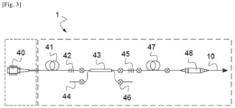
- an amplified spontaneous emission source (ASE for “Amplified Stimulated Emission”) illustrated in [ Fig.3 ].
- Source 1 of the [ Fig.3 ] comprises a pump diode 40 connected via an optical fiber 41 to a coupler-multiplexer 43.
- the pump diode 40 emits a pump signal at a pump wavelength, for example 980 nm.
- a first Bragg grating 42 is placed upstream of the coupler-multiplexer 43 and configured to promote the emission of the laser diode at a precise wavelength, here 980 nm.
- the coupler-multiplexer 43 receives the pump signal filtered at 980 nm on an input channel.
- the coupler-multiplexer 43 receives on another input channel 44 a signal to be amplified at a wavelength determined as a function of the amplifying medium. In the case of an ASE erbium source, the wavelength of the signal to be amplified is 1550 nm.
- a second Bragg grating 45 is placed downstream of the coupler-multiplexer 43 and configured to promote stable emission at 1550 nm by the optical amplifier medium 47, here consisting of an erbium-doped optical fiber.
- the pump signal at 980 nm and the signal to be amplified at 1550 nm are injected into the erbium-doped amplifying fiber.
- An optical isolator 48 is arranged at the output of the amplifying fiber to transmit the light beam 10 to 1550 nm emitted by the source 1.
- Source 1 thus performs the optical conversion of the polarized pump beam emitted by the pump laser diode, for example at 980 nm or 1480 nm, into a light beam at a wavelength in the telecom band (1532-1550 nm).
- the photons emitted at telecom wavelength are emitted spontaneously so that the light beam emitted in the telecom band is non-polarized.
- This light source is then non-polarized.
- the light beam 10 generated by amplified stimulated emission is non-polarized.
- the optical coupler-splitter 2 is not polarization maintaining or polarizing.
- the first part of the light beam 11 and the second part of the light beam 12 are non-polarized.
- the dosimeter 100 based on such a non-polarized source can use standard optical components and in particular a radiosensitive optical fiber 3 of single-mode (SM) or multi-mode (MM) type which is not polarization-maintaining.
- SM single-mode
- MM multi-mode
- the reference arm 4 is then based on components which are not polarization maintaining, for example a standard optical fiber section (SM) or a multimode optical fiber section (MM).
- SM standard optical fiber section
- MM multimode optical fiber section
- polarimeters for example based on rotating polarizers, which make it possible to measure the state of polarization of a light beam.
- a non-polarized light beam for example, we measure an identical power in the two transverse polarization modes and no phase coherence between them.
- the use of an erbium ASE source makes it possible to eliminate polarization fluctuations on RIA measurements.
- a polarized source 1 is used combined with a passive or active optical device to average the polarization of the light beam 10 source.
- a source is used comprising a superluminescent diode (SLED) which emits a polarized light beam. Downstream of the polarized source, there is an active or passive optical component to depolarize the light beam emitted by the source.
- SLED superluminescent diode
- the passive optical device is of the Lyot depolarizer type.
- the principle of the Lyot depolarizer is to make the two components of the transverse polarization follow different optical paths and whose optical path length is greater than the coherence length of the source and then to recombine the two polarizations.
- the Lyot depolarizer can be made by end-to-end welding two sections of polarization-maintaining optical fibers with proper axes misaligned by 45 degrees from each other. In this case the two optical paths correspond to the two indices of the PM fiber.
- a polarization combiner is used to inject the two transverse polarization components into different PM fibers and recombine them at the output.
- a passive depolarizer is particularly well suited to a light source having a relatively low coherence length, such as example a superluminescent diode (SLED).
- SLED superluminescent diode
- the active optical device is of the polarization jammer type.
- This active optical device is configured to modulate the phase randomly in order to break the coherence of the source and its polarization.
- the active optical device comprises an optical phase modulator, for example an electro-optical modulator.
- an active optical device is formed by applying a tailored mechanical stress on the fiber itself to modulate the phase randomly.
- the source 1 is polarized
- the radiosensitive optical fiber 3 is a polarization maintaining (PM) fiber and the entire optical chain between the source 1 and the photodetectors 5, 6 is polarization maintaining.
- this radiosensitive optical fiber 3 is manufactured by doping the core or the optical cladding of a conventional PM fiber, for example with phosphorus doping.
- the optical coupler-splitter 2 maintains polarization.
- the first part of the light beam 11 and the second part of the light beam 12 are polarized.
- the welds on the source side and on the coil side are carried out so as to align the proper axes of the radiosensitive optical fiber 3 maintaining polarization relative to the proper axes of the polarized source.
- the proper axes of the reference arm 4 are aligned with the proper axes of the polarized source.
- the first part of the light beam 11 and the second part of the light beam 12 are thus polarized.
- the polarization of the light beam then being preserved during propagation in the radiosensitive optical fiber 3 and in the reference arm 4, the PDL has no influence on the measurement of attenuation induced by irradiation.
- the dosimeter comprises at least two sources emitting at two distinct wavelengths, each source being connected to a suitable optical fiber.
- the two sources are polarized and the two radiosensitive optical fiber coils are polarization maintaining optical fibers.
- both sources are apolarized or depolarized.
- the dosimeter comprises a first polarized source associated with a radiosensitive optical fiber maintaining polarization and a second apolarized or depolarized source. The combination of two sources at two different wavelengths allows for redundancy of measurements and therefore an improvement in precision.
- a single source is adapted to emit the light beam at several wavelengths, for example at 16 distinct wavelengths.
- a single light source 1 is used coupled simultaneously to several coils of radiosensitive optical fibers, for example to two or three coils of optical fiber of different lengths and/or having different sensitivity to ionizing radiation, in addition to the reference arm 4.
- A for example another radiosensitive optical fiber and a beam splitter placed between the light source 1, the radiosensitive optical fiber 3 and the other radiosensitive optical fiber.
- the beam splitter receives the light beam 10 from the light source and divides it between the radiosensitive optical fiber 3 and the other radiosensitive optical fiber.
- the divider is located upstream of coupler 2. It can be a 1xN color type power divider or a multiplexer which allows the different coils to be addressed sequentially. Each coil needs its own reference arm.
- another photodetector is associated with the other radiosensitive optical fiber and arranged to record another power measurement of the light beam transmitted through the other radiosensitive optical fiber.
- the electronic system 20 is here adapted to receive the other power measurement from the other photodetector, simultaneously with the measurement of the reference arm.
- the electronic system 20 is configured to extract another differential measurement of attenuation induced by irradiation in the other radiosensitive optical fiber relative to the reference optical arm.
- the drastic reduction of the effects of polarization in the fiber optic dosimeter makes the dosimeter less sensitive to ambient thermal variations. Reducing polarization fluctuations in the fiber optic dosimeter thus makes it possible to lower the detection threshold for low doses of radiation, to improve the precision of RIA measurements and also to increase the dynamic dose measurement.
- the combination of an electronic system based on a logarithmic amplifier and the reduction of polarization effects makes it possible to lower the threshold for detecting low doses of radiation down to a few tens of microGy, to improve the precision of RIA measurements and also to increase the dynamic dose measurement to extend between 1 Gy and 100 Gy for example.
- the dosimeter of the present disclosure makes it possible to reduce detection noise by 1 to 2 orders of magnitude.
- the measured dose rate is in a range between 100 gray/d and 1 Mgray/d.
- the dosimeter of the present disclosure thus allows measurements of irradiation doses with remarkable precision of the order of 10 4 relative over a dynamic range extended over 10 dB.
- This architecture makes it possible to overcome power fluctuations of the light source 1.
- the differential measurement of RIA makes it possible to choose a light source 1 whose intensity is not necessarily stabilized as a function of time. For example, we choose an ASE source or a laser diode.
- the dosimeter can be packaged in a very compact box, for example a cylinder of approximately 40 mm in diameter and 20 mm in height and of low weight. THE dosimeter can thus be carried on board a space station or even in an astronaut's belt for an extravehicular exit.
- the dosimeter provides instant measurements.
- the box can be configured to transmit dose measurements, for example via a wireless connection to a display. These measurements make it possible, for example, to anticipate a solar flare likely to damage sensitive equipment.
- This point dosimeter can also find applications in the medical field for the point measurement of radiation dose produced by medical equipment, for example in pulsed radiotherapy. This point dosimeter also finds applications in the nuclear field, for the control or dismantling of all nuclear installations of the fusion or fission type.
Landscapes
- Physics & Mathematics (AREA)
- Health & Medical Sciences (AREA)
- Life Sciences & Earth Sciences (AREA)
- General Physics & Mathematics (AREA)
- High Energy & Nuclear Physics (AREA)
- Molecular Biology (AREA)
- Spectroscopy & Molecular Physics (AREA)
- Measurement Of Radiation (AREA)
- Photometry And Measurement Of Optical Pulse Characteristics (AREA)
Applications Claiming Priority (1)
| Application Number | Priority Date | Filing Date | Title |
|---|---|---|---|
| FR2212028A FR3142263B1 (fr) | 2022-11-18 | 2022-11-18 | Dosimètre à fibre optique pour environnement spatial et procédé de dosimétrie |
Publications (2)
| Publication Number | Publication Date |
|---|---|
| EP4372425A1 true EP4372425A1 (de) | 2024-05-22 |
| EP4372425B1 EP4372425B1 (de) | 2026-02-18 |
Family
ID=85937465
Family Applications (1)
| Application Number | Title | Priority Date | Filing Date |
|---|---|---|---|
| EP23210442.2A Active EP4372425B1 (de) | 2022-11-18 | 2023-11-16 | Faseroptisches dosimeter für räumliche umgebung und dosimetrieverfahren |
Country Status (4)
| Country | Link |
|---|---|
| US (1) | US20240168177A1 (de) |
| EP (1) | EP4372425B1 (de) |
| JP (1) | JP2024074276A (de) |
| FR (1) | FR3142263B1 (de) |
Cited By (1)
| Publication number | Priority date | Publication date | Assignee | Title |
|---|---|---|---|---|
| CN119805526A (zh) * | 2024-12-04 | 2025-04-11 | 南京航空航天大学 | 一种在线分布式光纤辐射剂量测量的装置、方法及计算机设备 |
Citations (4)
| Publication number | Priority date | Publication date | Assignee | Title |
|---|---|---|---|---|
| WO2001082426A2 (en) * | 2000-04-27 | 2001-11-01 | Sdl, Inc. | Depolarized semiconductor laser sources |
| WO2008054339A2 (en) * | 2005-06-03 | 2008-05-08 | Beinhocker Gilbert D | Tamper-proof container |
| EP2591387B1 (de) * | 2010-07-09 | 2019-02-20 | Ixblue | Strahlungsresistente seltenerddotierte glasfaser und verfahren zur strahlungshärtung einer seltenerddotierten glasfaser |
| CN111505695B (zh) * | 2020-04-26 | 2021-12-31 | 北京光衡科技有限公司 | 基于掺杂光纤自激辐射的辐射剂量仪 |
-
2022
- 2022-11-18 FR FR2212028A patent/FR3142263B1/fr active Active
-
2023
- 2023-11-16 EP EP23210442.2A patent/EP4372425B1/de active Active
- 2023-11-17 US US18/512,596 patent/US20240168177A1/en active Pending
- 2023-11-17 JP JP2023195680A patent/JP2024074276A/ja active Pending
Patent Citations (4)
| Publication number | Priority date | Publication date | Assignee | Title |
|---|---|---|---|---|
| WO2001082426A2 (en) * | 2000-04-27 | 2001-11-01 | Sdl, Inc. | Depolarized semiconductor laser sources |
| WO2008054339A2 (en) * | 2005-06-03 | 2008-05-08 | Beinhocker Gilbert D | Tamper-proof container |
| EP2591387B1 (de) * | 2010-07-09 | 2019-02-20 | Ixblue | Strahlungsresistente seltenerddotierte glasfaser und verfahren zur strahlungshärtung einer seltenerddotierten glasfaser |
| CN111505695B (zh) * | 2020-04-26 | 2021-12-31 | 北京光衡科技有限公司 | 基于掺杂光纤自激辐射的辐射剂量仪 |
Cited By (1)
| Publication number | Priority date | Publication date | Assignee | Title |
|---|---|---|---|---|
| CN119805526A (zh) * | 2024-12-04 | 2025-04-11 | 南京航空航天大学 | 一种在线分布式光纤辐射剂量测量的装置、方法及计算机设备 |
Also Published As
| Publication number | Publication date |
|---|---|
| FR3142263B1 (fr) | 2024-12-13 |
| EP4372425B1 (de) | 2026-02-18 |
| US20240168177A1 (en) | 2024-05-23 |
| JP2024074276A (ja) | 2024-05-30 |
| FR3142263A1 (fr) | 2024-05-24 |
Similar Documents
| Publication | Publication Date | Title |
|---|---|---|
| EP2972086B1 (de) | Interferometrische glasfaser-messvorrichtung mit einem ringresonator, gyrometer und trägheitshaltung oder navigationseinheit mit solch einer vorrichtung | |
| US8229304B1 (en) | Phase control of a fiber optic bundle | |
| US20150253187A1 (en) | Characterization of Single-Photon Detectors Using a Continuous Wave Laser Source | |
| WO2018207163A2 (fr) | Dispositif optoélectronique de mesure répartie par fibre optique | |
| EP3472558B1 (de) | Messsystem und gyrometer mit solch einem system | |
| CA2247186A1 (fr) | Dispositif de compensation de la dispersion de polarisation dans un systeme de transmission optique | |
| EP3033812B1 (de) | Gepulster multifrequenzlaseremitter und differenzabsorptions-lidar mit solch einem laseremitter | |
| FR2942876A1 (fr) | Instrument et procedure d’inspection d’une fibre optique | |
| EP3353502B1 (de) | Messsystem und temperatur und/oder formänderungssensor mit brillouinrückreflexionsanalyse | |
| FR2988488A1 (fr) | Appareil et procedes utilisant des capteurs optiques fonctionnant dans le mode de reflexion. | |
| EP4372425B1 (de) | Faseroptisches dosimeter für räumliche umgebung und dosimetrieverfahren | |
| FR2779531A1 (fr) | Detecteur de rayonnement, systeme de mesure de rayonnement et procede de mesure de rayonnement | |
| Chen et al. | Highly sensitive fiber coupling for free-space optical communications based on an adaptive coherent fiber coupler | |
| FR3125658A1 (fr) | Système de communication quantique par photons intriqués | |
| EP0618691B1 (de) | Evaluationsanordnung der Übertragungsqualität einer optischen Verstärkungseinrichtung | |
| EP2462405B1 (de) | Interferometer mit einer glasfaser mit hoher pmd im gekoppelten modus, glasfasergyroskop und trägheitsnavigationssystem mit einem solchen gyroskop | |
| WO2025012096A1 (fr) | Systeme lidar a detection directe | |
| Shu et al. | Computational Brillouin optical time-domain reflectometry | |
| FR3138207A1 (fr) | Système de capteur à fibre optique distribué | |
| FR3105825A1 (fr) | Dispositif de mesure optique d’un paramètre physique | |
| Li et al. | Ionizing radiation impact on communications performance of optical multi-hop inter-satellite relay link | |
| Mikhailov et al. | In-line high-speed all-fiber polarimeter with true real-time acquisition for sensor systems based on fast polarization rotation | |
| FR2570186A1 (fr) | Procede et dispositif de mesure du taux de polarisation | |
| FR3157543A1 (fr) | Procédé de quantification par spectrométrie Raman | |
| EP0559549A1 (de) | Vorrichtung zur optoelektronischen Detektion mit Verwendung der optischen Amplifikation, und Anwendung bei Telemetrie und Winkelabweichungsmessung |
Legal Events
| Date | Code | Title | Description |
|---|---|---|---|
| PUAI | Public reference made under article 153(3) epc to a published international application that has entered the european phase |
Free format text: ORIGINAL CODE: 0009012 |
|
| STAA | Information on the status of an ep patent application or granted ep patent |
Free format text: STATUS: THE APPLICATION HAS BEEN PUBLISHED |
|
| AK | Designated contracting states |
Kind code of ref document: A1 Designated state(s): AL AT BE BG CH CY CZ DE DK EE ES FI FR GB GR HR HU IE IS IT LI LT LU LV MC ME MK MT NL NO PL PT RO RS SE SI SK SM TR |
|
| STAA | Information on the status of an ep patent application or granted ep patent |
Free format text: STATUS: REQUEST FOR EXAMINATION WAS MADE |
|
| 17P | Request for examination filed |
Effective date: 20241011 |
|
| RBV | Designated contracting states (corrected) |
Designated state(s): AL AT BE BG CH CY CZ DE DK EE ES FI FR GB GR HR HU IE IS IT LI LT LU LV MC ME MK MT NL NO PL PT RO RS SE SI SK SM TR |
|
| GRAJ | Information related to disapproval of communication of intention to grant by the applicant or resumption of examination proceedings by the epo deleted |
Free format text: ORIGINAL CODE: EPIDOSDIGR1 |
|
| GRAP | Despatch of communication of intention to grant a patent |
Free format text: ORIGINAL CODE: EPIDOSNIGR1 |
|
| GRAP | Despatch of communication of intention to grant a patent |
Free format text: ORIGINAL CODE: EPIDOSNIGR1 |
|
| STAA | Information on the status of an ep patent application or granted ep patent |
Free format text: STATUS: GRANT OF PATENT IS INTENDED |
|
| INTG | Intention to grant announced |
Effective date: 20251104 |
|
| GRAS | Grant fee paid |
Free format text: ORIGINAL CODE: EPIDOSNIGR3 |
|
| GRAA | (expected) grant |
Free format text: ORIGINAL CODE: 0009210 |
|
| STAA | Information on the status of an ep patent application or granted ep patent |
Free format text: STATUS: THE PATENT HAS BEEN GRANTED |